
Submitted:
17 June 2025
Posted:
17 June 2025
You are already at the latest version
Abstract
Integration of missile launch capabilities into mobile ground platforms introduces significant engineering challenges, particularly in maintaining structural integrity under nonlinear transient dynamics induced by high-impulse loading. Previous studies have primarily addressed fixed or heavy launch platforms, comparatively fewer have examined high mobility vehicle-integrated air defense systems nonlinear coupling. The development of simulation environment replicating real-world launch conditions remains an active area of investigation in context of military personnel training, especially as platforms undergo rapid modernization and next-generation weapons systems are introduced. This study proposes a nonlinear computational framework to simulate launch-induced dynamic response of an air defense system mounted on a high mobility multipurpose wheeled vehicle (HMMWV). A five degree-of-freedom model was developed using Lagrangian mechanics. The second-order differential equations of the model were numerically solved using the fourth order Runge-Kutta method. Simulations were performed at three launcher pitch angles (30°, 45°, and 60°) enabling high-resolution analysis of recoil-induced oscillations, impulse propagation and system stabilization times. The results reveal interaction between propulsion-generated excitation force and chassis performance, which is significantly influenced by geometrical parameters of chassis components. The validated modelling framework offers application for improved mobile air defense systems performance and simulation-based training environments and future system integration studies.
Keywords:
nonlinear dynamics
; missile launch dynamics
; impulse excitation modeling
; dynamic response
; nonlinear vehicle dynamics
; dynamic load simulation
; multibody dynamic simulation
; launcher-vehicle coupling analysis
1. Introduction
The integration of advanced missile launch capabilities onto the ground mobile platforms creates exceptionally effective weapon system which allows to rapidly distribute surface-based air and missile defense (SBAMD) capabilities across the land domain preserving the security and integrity of airspace during peacetime as well as wartime situations whenever it is necessary to confront the adversary and quickly shift the focus and strategy in order to increase survivability and mission success.
Vehicle-integrated advanced missile launcher capabilities development as well as practical applications require comprehensive knowledge to successfully deal with engineering challenges. The complexities of the vehicle-integrated SBAMD systems arise as modern military operations require highly maneuverable mobile air defense platforms to be able to operate under diverse environmental conditions and remain highly reliable as well as effective thus maintaining high operational readiness. These platforms must withstand a combination of dynamic forces during the missile launch phase and effectively damp the missile induced oscillations thus maintaining the structural integrity of the vehicle and launch platform. Despite the extensive research on fixed missile launch systems, the dynamic behavior of missile launch systems integrated into high-mobility vehicles remain insufficiently explored.
Furthermore, an additional key research area is the development of mathematical models for the air defense system simulators to mimic real-world missile launch conditions. Modern weapon systems design and implementation require advanced modelling and simulations in order to accurately predict the air defense systems performance, to ensure reliability under different operation conditions, and to perform the design optimization. The vehicle-integrated air defense system accurate behavior prediction under high-impulse loading directly impacts missile launcher performance, contributes to mission success and supports military personnel training activities. As the military platforms undergo rapid modernization processes and next-generation weapons systems are introduced the shortcoming of military personnel varying knowledge, competencies and skills engaged in SBAMD/IAMD missions must be improved in order to simulate real-world conditions thus enhancing training experience and contributing to mission success by executing SBAMD/IAMD tasks.
Advancements in rocket guidance technologies have significantly enhanced the effectiveness of mobile weapon systems [1]. Increasing demand to improve both the mobility and dynamic response [2] of mobile fire units to meet the operational requirements remains area of high interest [1,3,4,5]. A critical aspect of this development involves minimizing launch-induced vibrations, which directly contributes to reduction rockets’ deviation and improvement of firing accuracy as well as overall system reliability and performance [1,3,5,6,7,8,9,10,11,12]. The integration of control systems with MLRS dynamic simulations are frequently insufficiently unified with real-world firing scenarios replicating excitation sources [1]. Vehicle suspension system technology advancements employing adaptive control measures like electromagnetic active suspension provide valuable insights into vehicle suspension and overall vehicle performance improvements driving at high-speeds on uneven roads [2]. By modeling the system as coupled rigid and elastic bodies it is possible to address the complex mechanical behavior of mobile rocket launcher systems and investigate mobile rocket launcher system interaction as well as clarify on how vibrations and structural parameters impact the launch stability and rocket flight paths [3]. Laucher dynamics tend to intensify with increasing elevating angle [3].
Research of weapon systems performance which are mounted onto HMMWV contributes to accurate assessment of possibilities to mount more powerful weapon systems onto mobile platform furthermore investigating their influence on vehicle chassis performance and overall integrated weapon system recoil response [4]. Dynamic response of multiple-body system coupling vehicle mechanics with missile launcher dynamics are commonly solved numerically demonstrating the effectiveness of mathematical methods solving non-linear and time-dependent coupled systems [1,3,5,6,7,8,9,10,11,12]. Dynamic model development assists in developing the computational framework for investigating the influence of vehicle-integrated weapon system performance and the results provide valuable insights for rocket launch time optimization minimizing its effect on rocket launch system as well as minimizing multiple rocket launch dispersion [3].
The non-linear dynamics of the HMMWV equipped with weapon system during the firing phase are examined considering the vehicle’s chassis and associated elements performance [4]. Dynamic model development contributed to research of the vehicle-integrated weapon system performance at the moment of firing [4,5,6].
Classical mechanics principles through Langrange differential equations are frequently solved using MATLAB software [4,5]. Lumped-parameter model development based on Lagrangian mechanics is an efficient and yet accurate representation of dynamic response after the mobile firing unit (MFU) has been excited by first-stage of the missile launch [5]. The results reveal that using fourth order Runge-Kutta method in MATLAB software to solve second-order differential equations creates favorable conditions to perform in-depth analysis of how effectively vehicle suspension components effectively attenuate the dynamic impulse therefore providing valuable insights into vehicle-integrated system behavior enhancing dynamic response prediction thus enhancing the accuracy [5]. Creation of highly detailed computational framework to investigate MFU models’ performance after missile launch allows to observe coupled system interactions and could contribute to development of training simulators for military personnel [5].
Dynamic model simulations with the application of external impulse are frequently used to investigate the dynamics of the system and their components performance [6]. Adaptive control strategies development and implementation remain the active area of research in order to improve system performance thus reducing vibrations in the system [6,22]. Despite the considerable effort put into research analyzing adaptive systems employment with the use of active and passive control methods, these have limited application for robust military vehicles operating in harsh environment enhancing the stability of vehicle-integrated missile launch systems [1].
The main aim of the presented study is to analyze the factors influencing the missile’s motion during launch from a launching system mounted on a HMMWV, with particular emphasis on thrust force generated by the missile engine and its effect on the dynamic performance of the vehicle-integrated launch system, as well as the structural loads acting upon it. This research involves developing both a dynamic and a mathematical model scheme of the missile launch system integrated into vehicle. The study investigates the influence of propulsion-generated thrust on the overall system dynamics and identifies the peak values as well as the oscillations initiation start and end times of dynamic processes after missile launch. It also analyses the dynamic load affecting the vehicle-integrated missile launch system during the launch phase and proposes potential solutions in order to mitigate the negative effects on air defense system performance. The validated modeling framework could enhance the performance of mobile air defense systems, support simulation-based training environments without the expenses of live firing exercise, and simplify future studies on system integration.
2. Computational Framework Development
In this section the computational framework is developed to simulate the dynamic behavior of the vehicle-integrated missile launch system with the emphasis on formulating the dynamic and mathematical models, selecting the appropriate numerical method in order to solve the governing equations.
The framework developed aims to accurately replicate the multibody structural performance under dynamic loading conditions thus providing reliable means to monitor system performance with high accuracy and serves as a tool for military personnel training purposes replicating real-world dynamic loading conditions.
2.1. Dynamic Model
The dynamic interaction during the initial stage of missile launch between the launch system and the High Mobility Multipurpose Wheeled Vehicle (HMMWV) will be analyzed based on the methodology presented in scientific articles [2,3,4,5,6,10,12]. This study applies classical mechanics principles along with calculations of kinetic, potential, and total energy. The research involves the analysis of the effects of missile launch dynamics on both the HMMWV and the missile launch system equipped with the missiles. The dynamic model scheme of the vehicle-integrated air defense launch system mounted was developed by considering the dynamic models and classical mechanics principles outlined in the scientific articles [2,3,4,5,6,10,12].
2.2. Mathematical Model
The mathematical model of the vehicle-integrated air defense system is described by five second-order Lagrangian differential equations, taking into account the dynamic model scheme and based on the analysis of scientific sources [2,3,4,5,6,10,12]. A generalized equation of the forces acting on the system is presented 1st equation as follows:
where is the kinetic energy, is the potential energy, is the damping energy and represents the external force load (missile launch first phase excitation force ).
Based on the dynamic model of the HMMWV with the integrated missile launch system (see Figure 1), the kinetic energy equation for the system is presented in 2nd equation as follows:
where is the kinetic energy of the system.
The dynamic model under analysis comprises two types of potential energy—spring energy and gravitational potential energy. The springs store potential energy, which is proportional to the square of the deformation. The potential energy equation for the system is presented in 3rd equation:
where is the potential energy.
Considering equation (1), it is evident that, in addition to kinetic and potential energy, an important term in the equation is , the energy dissipation (damping) term. Damping energy is an important measure describing the instant rate of energy change—that is, how rapidly external excitation force is dissipated via dampers and other components within the system. Each damper in the system contributes to the overall damping behavior of vehicle-integrated air defense system depending on its location within the system.
In the dynamic model scheme, it can be seen that during system excitation by external force, six damping elements act on the system, each possessing a specific contribution to the total system response behavior. The dampers are interconnected via multiple nodes, that is the vehicle chassis and its axle, the vehicle chassis and the missile launch system, thereby creating conditions for coupling interactions between and via , between and via , between and via . The damping energy equation is provided as follows:
where is the damping energy.
The mathematical model will be expressed by five second-order differential equations 5-9 as follows:
where is the acceleration due to gravity, .
The 6th equation describes the vertical equilibrium of the front unsprung mass :
The differential equation 7 characterizes the vertical equilibrium of the combined masses of the vehicle body and missile launch system, as follows:
The vehicle body pitch is dependent on the total kinetic energy of the vehicle body mass and the rotational kinetic energy of the launch mechanism about the vehicle’s center of mass, and it is described by the corresponding 8 equation:
The equation 9 represents the dynamics of the launch angular displacement as follows:
The governing five second-order differential equations with five generalized coordinates and velocities present a system of equations 10 as follows:
The system of differential equations will be expressed in matrix form since the simulation of missile launcher nonlinear dynamics will be solved using MATLAB software. Equations in form of matrices will provide much more structured and actually easier way to understand vehicle-integrated air defense system performance. The matrix form will also allow to incorporate the influence of dynamic impulse after the missile launch and the gravitational forces acting on the system both at rest and during the missile launch in much clearer way as follows:
where is the mass-inertia matrix, is the damping matrix, is the stiffness matrix, is the generalized coordinate vector, is the external impulse vector, is the missile launch first phase excitation force, and the is gravitational force vector.
When external force acts on the system, the mass-inertia matrix M determines the amount of acceleration generated in the system’s components in response to a given magnitude of force applied.
where is the inertia moment of the missile launcher about the hinge point.
The damping matrix characterizes the forces arising from changes in velocity. Damping is an essential parameter for the vehicle-integrated air defense system to dissipate energy through friction and internal losses ceasing the oscillations. Interactions between elements, such as , indicate that the damper influences both translational and rotational motions as follows:
The stiffness matrix describes the spring stiffness forces that arise due to displacements. The higher the value of spring stiffness, the stiffer is the system, which links to a higher frequency of vibrations. The stiffness matrix characterizes the system’s resistance to deformation as follows:
The missile launch system will generate an impulse only through the rotation of the missile launch system. Vector L has a nonzero value only in its fifth component. The external impulse – which represents missile propulsion generated dynamic impulse - is produced during the first phase of missile launch and manifests itself around the attachment point of the rotational joint.
Gravitational forces act entirely on linear motions such as . The assumption is made that gravity does not have a direct impact on the moments and . Gravitational force vector is given as follows:
2.3. Numerical Simulation Input Parameters and Boundary Conditions
This section presents the primary boundary conditions implemented for simulations of nonlinear dynamic process triggered by the first phase of the missile launch.
The object of the study is a currently operational military armored vehicle HMMWV equipped with a missile launch system. Since the mobile vehicle-integrated air defense systems are currently operational, obtaining the precise data with exact parameters for numerical simulation is practically unfeasible, therefore simulation input parameters for the study will be selected after in-depth research articles and journals analysis [1-31] providing reliable sources of input for the dynamic model simulation which are provided in Table 2.
The system of ODEs will be solved using MATLAB software with the application of the Runge-Kutta method and the MATLAB ODE45 function. At the initial time moment, when the system is at steady state, HMMWV is not moving . Numerical simulations will be performed at three different launcher pitch angles which are as follows: 30°, 45°, and 60°, enabling observations of system oscillations induced by external force pulse excited. The thrust force generated by the missile propulsion during its first launch phase from the stand was modeled as a dynamic impulse acting for a duration of time from the start of the numerical simulation, with an impulse value of .
The response of vehicle-integrated missile launch system will be obtained by incorporating the dynamic simulation parameters required to solve the system of differential equations given in Table 2.
3. Results
This section presents the key findings after carrying out a numerical simulation of a vehicle-integrated air defense system with the use of the Runge-Kutta method and the MATLAB ODE45 function. Simulation outcomes demonstrate significant interaction between the excitation force generated by the missile thrust, missile launcher dynamics as well as HMMWV chassis dynamics which were greatly affected by the geometric parameters and design of the chassis components.
For each simulation sequence carried out at different launcher pitch angles (30°, 45°, and 60°), initial conditions remained the same - at the system is at a steady state, HMMWV is not moving .
The duration of the dynamic impulse acting on the system remained the same for each launch at different pitch angles from the start of the numerical simulation, with an impulse value of (see Figure 2).
3.1. Linear and Angular Displacements
When the missile launch dynamic impulse excites the missile launch system mounted on HMMWV, a dynamic response of the structure is initiated.
The first case analyzes the structural dynamic response to the missile launch at 30° angle. Initially, it can be observed in Figure 3, Table 3 and Table 4 that the linear displacement in the vertical direction of the system mass , denoted as , began oscillating at 0.04 s, with the oscillations ending at 0.55 s. The displacement reached a maximum value of 0.0009 m.
Similarly, the linear displacements in the vertical direction of masses and , denoted as and , were observed. The oscillations of vertical linear displacement started at 0.01 s and ended at 1.12 s, reaching a peak value of 0.0118 m. The linear displacement of mass was monitored from 0.03 s, with oscillations concluding at 0.99s, it reached a maximum value of 0.0009 m. The angular displacement of mass began oscillating at 0.01 s and ceased at 1.35 s, reaching a peak value of 0.01702 rad. The angular displacement of mass was observed starting at 0.02 s, with oscillations ending at 0.68 s, it reached a maximum value of 0.0059 rad.
In the second case, the dynamic response to a missile launch at a 45° angle is analyzed. The numerical simulation results are displayed in Figure 4, Table 3 and Table 4.
The results in Figure 4, Table 3 and Table 4 reveal that linear vertical displacement of the system mass , designated as , began oscillating at 0.05 s and stabilized at 0.37 s when missile launcher pitch angle was at 45°. The displacement has reached a maximum value of 0.0004 m. Moreover, linear vertical displacements of masses and , designated as and , were analyzed. The oscillations of vertical linear displacement initialized at 0.02 s and stabilized at 0.62 s, achieving a peak value of 0.0079 m. The linear displacement of mass initiated from 0.03 s, with oscillations stabilizing at 0.88 s, it achieved a maximum value of 0.0008 m. The angular displacement of mass began oscillating at 0.01 s and stabilized at 1.25 s, attaining a peak value of 0.01511rad. The angular displacement of mass initiated at 0.02 s, with oscillations ending at 0.34 s, it reached a maximum value of 0.00327 rad.
In the third case, the structural dynamic response to a missile launch at a 60° angle was analyzed. To begin with, numerical simulation outcomes can be observed in Figure 5, Table 3 and Table 4. The linear displacement in the vertical direction of the system mass , designated as , began oscillating at 0.06 s and ended at 0.2 s. The displacement reached a maximum value of 0.0002 m.
Correspondingly, the linear displacements in the vertical direction of masses and , designated as and , were observed. The oscillations of vertical linear displacement started at 0.02 s and ended at 0.41 s, attaining a peak value of 0.0041 m. The linear displacement of mass was observed from 0.03 s, with oscillations ending at 0.81 s, it reached a maximum value of 0.0006 m. The angular displacement of mass began oscillating at 0.01 s and ended at 1.17 s, reaching a peak value of 0.01244 rad. The angular displacement of mass was observed starting at 0.03 s, with oscillations ending at 0.28 s, it reached a maximum value of 0.00163 rad.
3.2. Linear Velocities and Accelerations
During the investigation of the dynamic model of the missile launch system mounted on the HMMWV, the changes in the linear velocity and acceleration were analyzed.
In the first case, the dynamic response of the structure to a missile launch at a 30° angle was analyzed. It is observed in Figure 6, Figure 7, Figure 8, Table 5 and Table 6 that the linear velocity of the system mass in the vertical direction, , began at 0.01 s and the oscillations ceased at 1.16 s. The maximum value of reached 0.0906 m/s. Linear acceleration of the system mass in the vertical direction, , began at 0 s and the oscillations stopped at 1.34 s. The maximum value of reached 2.567 m/s².
Similarly, the linear velocities and accelerations of masses and in the vertical direction, , , and were also observed. The oscillations of the vertical linear velocity for mass started at 0.02 s and ended at 0.72 s, reaching a maximum value of 0.0008 m/s. Linear acceleration oscillations of started at 0 s and ended at 0.89 s, with a peak value of 0.174 m/s2. The vertical linear velocity for mass was detected from 0.01 s, with oscillations stopping at 0.9 s, and attained a peak value of 0.0175 m/s. For , oscillations were observed beginning at 0 s and ended at 1.24 s, reaching a maximum value of 1.2956 m/s2.
In the second case, the dynamic response of the structure to a missile launch at a 45° angle was simulated. It is shown in Figure 6, Figure 7, Figure 8, Table 5 and Table 6 that the linear velocity of the system mass in the vertical direction commenced at 0.01 s and the oscillations ended at 0.69 s. The maximum value of was 0.0606 m/s. Similarly, the vertical linear velocities and for masses and were monitored. The oscillations for began at 0.02 s and ended at 0.63 s, reaching a maximum of 0.0009 m/s. The vertical linear velocity was observed from 0.01 s, with oscillations finishing at 0.89 s, and peaked at 0.0192 m/s. Linear acceleration of mass in the vertical direction, , began at 0 s and oscillations ended at 1.01 s. The peak value of was 2.1201 m/s². Corresponding accelerations for masses and , and , were also analyzed. The oscillations of lasted from 0 s to 0.88 s, with a maximum value of 0.0193 m/s². The oscillations of were recorded from 0 s to 1.19 s, reaching a peak value of 1.2528 m/s².
In the third case, the dynamic response of the structure to a missile launch at a 60° angle was simulated. It is shown in Figure 6, Figure 7, Figure 8, Table 5 and Table 6 that the linear velocity of the system mass in the vertical direction commenced at 0.01 s and the oscillations concluded at 0.41 s. The maximum value of was 0.0343 m/s.
Correspondingly, the vertical linear velocities and for masses and were monitored. The oscillations for started at 0.02 s and ended at 0.58 s, reaching a maximum of 0.0009 m/s. The vertical linear velocity was observed from 0.01 s, with oscillations finishing at 0.87 s, and peaked at 0.02 m/s. Linear acceleration of mass in the vertical direction, , began at 0 s and oscillations ended at 0.77 s. The peak value of was 1.5893 m/s². Corresponding accelerations for masses and , and , were also investigated. The oscillations of lasted from 0 s to 0.86 s, with a maximum value of 0.0199 m/s². The oscillations of were recorded from 0 s to 1.16 s, reaching a peak value of 1.1279 m/s².
3.2. Angular Velocities and Accelerations
During the investigation of the dynamic model of the missile launch system mounted HMMWV, highly detailed numerical simulation has been performed on the angular velocities and accelerations of the system masses , revealing valuable insights into the vehicle-integrated air defense system’s dynamic behavior under varying launch conditions.
In the first scenario, the dynamic response of the structure to a missile launch at a 30° angle was rigorously examined. As illustrated in Figure 9, Figure 10 and detailed in Table 7, Table 8, the angular velocity of system mass was triggered at 0.01 s, with oscillations ending by 0.59 s. reached a peak value of 0.00359 rad/s, indicating a significant transient dynamic behavior. Simultaneously, the angular velocity of mass was monitored, initiating at 0.01 s and stabilizing by 1.07 s, with a maximum vertical angular velocity of 0.06632 rad/s, underscoring the intense rotational dynamics induced by the launch. The angular acceleration of mass , , was initiated immediately at 0 s, with oscillations settling after 1.07 s. reached a peak value of 0.066 rad/s², indicating significant rotational excitation. The angular acceleration of mass , , oscillated from 0 s to 1.31 s, achieving a maximum vertical angular acceleration of 3.63792 rad/s², emphasizing dynamic effects on the system’s components.
In the second scenario, the dynamic response of the structure to a missile launch at a 45° angle was rigorously examined. As illustrated in Figure 9, Figure 10 and detailed in Table 7, Table 8, the angular velocity of system mass was triggered at 0.01 s, with oscillations ending by 0.38 s. reached a peak value of 0.00275 rad/s, indicating a significant transient dynamic behavior. Simultaneously, the angular velocity of mass was monitored, initiating at 0.01 s and stabilizing at 0.52 s, with a maximum vertical angular velocity of 0.05658 rad/s. The angular acceleration of mass , , was initiated immediately at 0 s, with oscillations settling after 0.51 s. reached a peak value of 0.05652 rad/s², indicating high value rotational excitation. The angular acceleration of mass , , oscillated from 0 to 0.99 s, achieving a maximum vertical angular acceleration of 3.82916 rad/s², emphasizing dynamic effects on the system’s components.
In the third case, analyzing the response at a 60° launch angle, showed the most unresponsive dynamic behavior among the three cases. As illustrated in Figure 9, Figure 10 and detailed in Table 7, Table 8, that of mass initiated at 0.01 s, with oscillations ceasing at 0.39 s and peaking at a reduced value of 0.00232 rad/s. Meanwhile, the angular velocity of mass fluctuated from 0.010 to 0.63 seconds, reaching a maximum vertical angular velocity of 0.04902 rad/s. Analyzing the response at a 60° launch angle, the angular acceleration for mass initiated at 0 s and rapidly ended by 0.63 s, with a maximum value of 0.04878 rad/s². However, of mass surged to its highest recorded peak of 4.08081 rad/s² within 0.89 s, highlighting the significant rotational dynamics on the missile launch system performance at higher launcher pitch.
4. Conclusions
- A nonlinear computational framework was developed in order to simulate the dynamic response of the air defense system mounted onto High Mobility Multipurpose Wheeled Vehicle (HMMWV);
- It was determined that the propulsion-generated thrust impulse force of has the greatest impact on the missile launch system when fired at a 30° pitch angle. The linear acceleration of the system’s mass in the vertical direction initiated at 0 s, with oscillations stabilizing at 1.34 s, reaching a maximum acceleration of 2.567 m/s²;
- The vertical linear acceleration exhibited the longest oscillation duration of 1.34 s at the 30° launch angle;
- At a 60° launch angle, the angular acceleration , began at 0 s and ended at 0.89 s, with peak value 4.08 rad/s². This angular acceleration at 60° was 12% higher than at 30°, and 7% higher than at 45°;
- Given that the air defense system mounted onto HMMWV carries four AIM-120 AMRAAM missiles, it was recognized that the second missile could only be launched after the dynamic impulse induced by the first missile diminishes. Specifically, for a 30° launch angle, the second missile can be fired not sooner than 1.34 s after the first, when the system’s dynamic oscillations return to equilibrium. For launch angles of 45° and 60°, these intervals are 1.25 s and 1.17 s, respectively. This identification of peak dynamic loads and missile launch system critical stabilization period after the missile launch indicates that the proposed computational framework holds significant potential to enhance performance of missile defense systems as well as to provide cost-effective military personnel training solutions in simulation environments thus adapting to next-generation weapon systems;
- Further research is highly recommended to explore adaptive control strategies – active and passive means – means to provide real-time feedback enhancing system performance and improving launch accuracy under the harsh operational conditions.
Author Contributions
Conceptualization, M.K.; methodology, M.K.; software, M.K.; validation, M.K. and S.K.; formal analysis, M.K.; investigation, M.K.; writing—original draft preparation, M.K.; writing—review and editing, M.K. and S.K.; visualization, M.K.; supervision, S.K.; All authors have read and agreed to the published version of the manuscript.
Funding
This research received no external funding.
Institutional Review Board Statement
Not applicable.
Informed Consent Statement
Not applicable.
Data Availability Statement
Not applicable.
Conflicts of Interest
The authors have no completing interests to declare that are relevant to the content of this article.
Abbreviations
The following abbreviations are used in this manuscript:
| ODE | Second-order system of ordinary differential equation |
| HMMWV | High mobility multipurpose wheeled vehicle |
| KTU | Kaunas University of Technology |
| MFU | Mobile Firing Unit |
| MLRS | Multiple Launch Rocket System |
| SBAMD | Surface Based Air and Missile Defense |
| IAMD | Integrated Air and Missile Defense |
| TBMD | Theatre Ballistic Missile Defense |
| ALTBMD | Active Layered Theatre Ballistic Missile Defense |
| DOF | Degrees-of-freedom |
References
- Qu, P.; Sun, Z.; Li, Q.; Zhang, J.; Liu, P.; Zhou, D. Dynamic Simulation of Multiple Launch Rocket System Marching Fire Based on the Fuzzy Adaptive Sliding Mode Control. Machines 2023, 11, 427. [CrossRef]
- Wu, L.; Zhou, R.; Bao, J.; Yang, G.; Sun, F.; Xu, F.; Jin, J.; Zhang, Q.; Jiang, W.; Zhang, X. Vehicle Stability Analysis under Extreme Operating Conditions Based on LQR Control. Sensors 2022, 22, 9791. [CrossRef]
- Eisa, H.; Ahmed, M.Y.M.; Khalil, M.; Saleh, S. Dynamic behavior of a wheeled rocket launcher using transfer matrix method of multibody system. J. Phys.: Conf. Ser. 2024, 2811, 012034.
- Fedaravičius, A.; Jonevičius, V.; Survila, A.; Pincevičius, A. Dynamics study of the carrier HMMWV M1151. J. Vibroeng. 2013, 15, 1619–1627.
- Fedaravičius, A.; Jasas, K.; Gaidys, R.; Pilkauskas, K. Dynamics of the Missile Launch from the Very Short-Range Mobile Firing Unit. Shock Vib. 2023, 2023, 3082704. [CrossRef]
- Krzysztofik, I.; Koruba, Z. Adaptive control of anti-aircraft missile launcher mounted on a mobile base. Theor. Appl. Mech. Lett. 2012, 2, 043008. [CrossRef]
- Zhou, Q. B.; Rui, X. T.; Wang, G. P.; Zhang, J. S. An efficient and modular modeling for launch dynamics of tubed rockets on a moving launcher. Defence Technol. 2021, 17, 1575–1586. [CrossRef]
- Liu, Z.; Wang, G.; Rui, X.; Wu, G.; Tang, J.; Gu, L. Modeling and simulation framework for missile launch dynamics in a rigid-flexible multibody system with slider-guide clearance. Nonlinear Dyn. 2024, 112, 21701–21728. [CrossRef]
- Li, B.; Rui, X.; Tian, W.; Cui, G. Neural-network-predictor-based control for an uncertain multiple launch rocket system with actuator delay. Mech. Syst. Signal Process. 2020, 140, 106489. [CrossRef]
- Fedaravičius, A.; Jasas, K.; Sližys, E.; Survila, A. Modeling of the missile launch dynamic processes in short-range air defence system. Mechanika 2022, 28, 32–37. [CrossRef]
- Dziopa, Z.; Koruba, Z. The impact of launcher turret vibrations control on the rocket launch. Bull. Pol. Acad. Sci: Tech. Sci. 2015, 63, 717–728. [CrossRef]
- Zhang, D.; Xiao, J. A dynamic model for rocket launcher with coupled rigid and flexible motion. Appl. Math. Mech. (Eng. Ed.) 2005, 26, 609–617.
- Fedaravičius, A.; Račkauskas, S.; Survila, A.; Šamelis, A. External ballistics simplified model of the RT-400 rocket aerial target. Problems of Mechatronics Armament, Aviation, Safety Eng. 2018, 9, 9–22.
- Rahnejat, H.; Johns-Rahnejat, P.M.; Dolatabadi, N.; Rahmani, R. Multi-body dynamics in vehicle engineering. Proc. Inst. Mech. Eng., Part K: J. Multi-body Dyn. 2023, 237, 398–427. [CrossRef]
- Sinha, P.K.; Chakraborty, D. Numerical study of hot launch of missile inside a tube. Proc. Inst. Mech. Eng. Part G: J. Aerosp. Eng. 2014, 228, 2604–2611. [CrossRef]
- Droppa, P.; Štiavnický, M. Vibrations simulation of wheeled vehicles. Problems of Mechatronics, Armament, Aviation, Safety Eng. 2012, 2 (8), 17–28.
- Van Vo, B.; Macko, M.; Thai Nguyen, D.; Duy Nguyen, P.; Thanh Nguyen, H.; Trong Bui, T. Dynamic simulation analysis and optimization of firing rate of rocket launchers on wheeled vehicles. Adv. Mil. Technol. 2021, 16, 159–175.
- Karakas, E. S.; Gordaninejad, F.; Evrensel, C. A.; Yeo, M.-S.; Liu, Y. Study of a quarter model HMMWV suspension system using a magnetorheological fluid damper. Problems of Mechatronics, Armament, Aviation, Safety Eng. 2012, 2 (8), 17–28.
- Abdelkareem, M. A. A.; Makrahy, M. M.; Abd El Tawwab, A. M.; El-Razaz, A. S. A.; Ali, M. K. A.; Moheyeldein, M. M. An Analytical Study of the Performance Indices of Articulated Truck Semi-Trailer during Three Different Cases to Improve the Driver Comfort. Proc. Inst. Mech. Eng. Part K: J. Multi-body Dyn. 2018, 232(1), 84–102. [CrossRef]
- Koruba, Z.; Dziopa, Z.; Krzysztofik, I. Dynamics of a controlled anti-aircraft missile launcher mounted on a moveable base. J. of Theor. Appl. Mech. 2010, 48, 279–295.
- Dziopa, Z. J.; Nyckowski, M. Modelling and testing the dynamic properties of a launcher with unguided missiles. Problems of Mechatronics, Armament, Aviation, Safety Eng. 2022, 13 (4), 51–66. [CrossRef]
- Surblys, V.; Sokolovskij, E. Lengvųjų automobilių pasyvių ir pusiau aktyvių pakabų tyrimas. Mokslas – Lietuvos ateitis / Sci. Future Lithuania. 2018, 10, 1–5.
- Liu, D. N.; Hou, Z. X.; Gao, X. Z. Nonlinear dynamics modelling and free-launch simulation of a flying vehicle. Proc. Inst. Mech. Eng., Part K: J. Multi-body Dyn. 2018, 232, 218–231.
- Fedaravičius, A.; Račkauskas, S.; Survila, A.; Patašienė, L. Design of the testing system for solid propellant rocket motor thrust measurements using mathematical modelling techniques. J. Meas. Eng. 2015, 3, 124–131.
- Fedaravičius, A.; Kilikevičius, S.; Survila, A.; Račkauskas, S. Short range rocket-target: research, development and implementation. Aircraft Eng. Aerosp. Technol. 2019, 91, 1027–1032. [CrossRef]
- Fedaravičius, A.; Račkauskas, S.; Sližys, E.; Survila, A. Investigation of solid rocket motor strength characteristics by employing composite materials. Mechanika 2014, 20, 247–253. [CrossRef]
- Briese, L.E.; Acquatella, P.; Schnepper, K. Multidisciplinary modeling and simulation framework for launch vehicle system dynamics and control. Acta Astronaut. 2020, 170, 652–664. [CrossRef]
- Neto, A.; de Oliveira, C.F. Analysis of parameters affecting the dynamic stability of a rocket launcher. J. Phys.: Conf. Ser. 2020, 1428, 012018.
- Vujic, D.; Djurkovic, V.; Milenkovic, N.; Trajkovic, S. Dynamic Analysis of Rockets Launcher. Tehnički Vjesnik 2021, 28, 530–539. [CrossRef]
- Wu, G.; Rui, X.; Wang, G.; Jiang, M.; Wang, X. Modelling and simulation of driving dynamics of wheeled launch system under random road surface excitation. Acta Mech. Sin. 2024, 40, 523310.
- Li, B.; Rui, X.; Wang, G.; Zhang, J.; Zhou, Q. On modeling and dynamics of a multiple launch rocket system. Proc. Inst. Mech. Eng. Part G: J. Aerosp. Eng. 2021, 235, 1664–1686. [CrossRef]
Figure 1.
Dynamic model of vehicle-integrated air defense system.
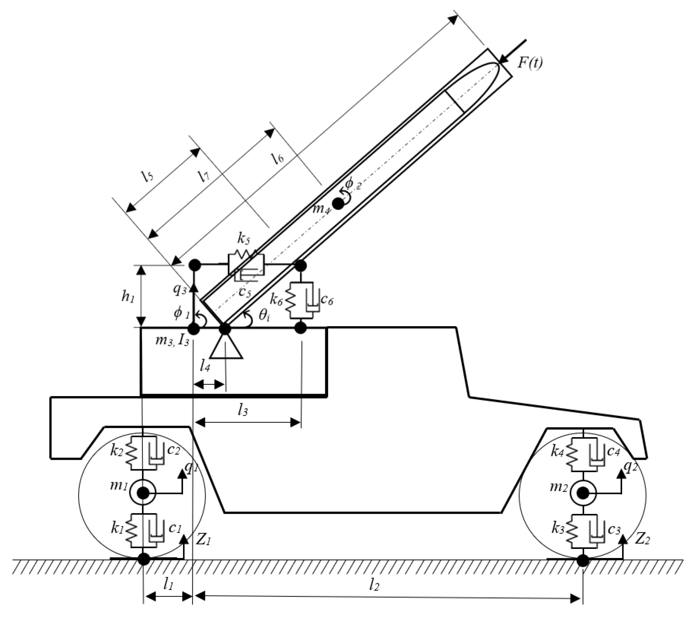
Figure 2.
Missile launch first phase excitation force dynamic impulse. Duration of the pulse t = 0.05s.
Figure 2.
Missile launch first phase excitation force dynamic impulse. Duration of the pulse t = 0.05s.
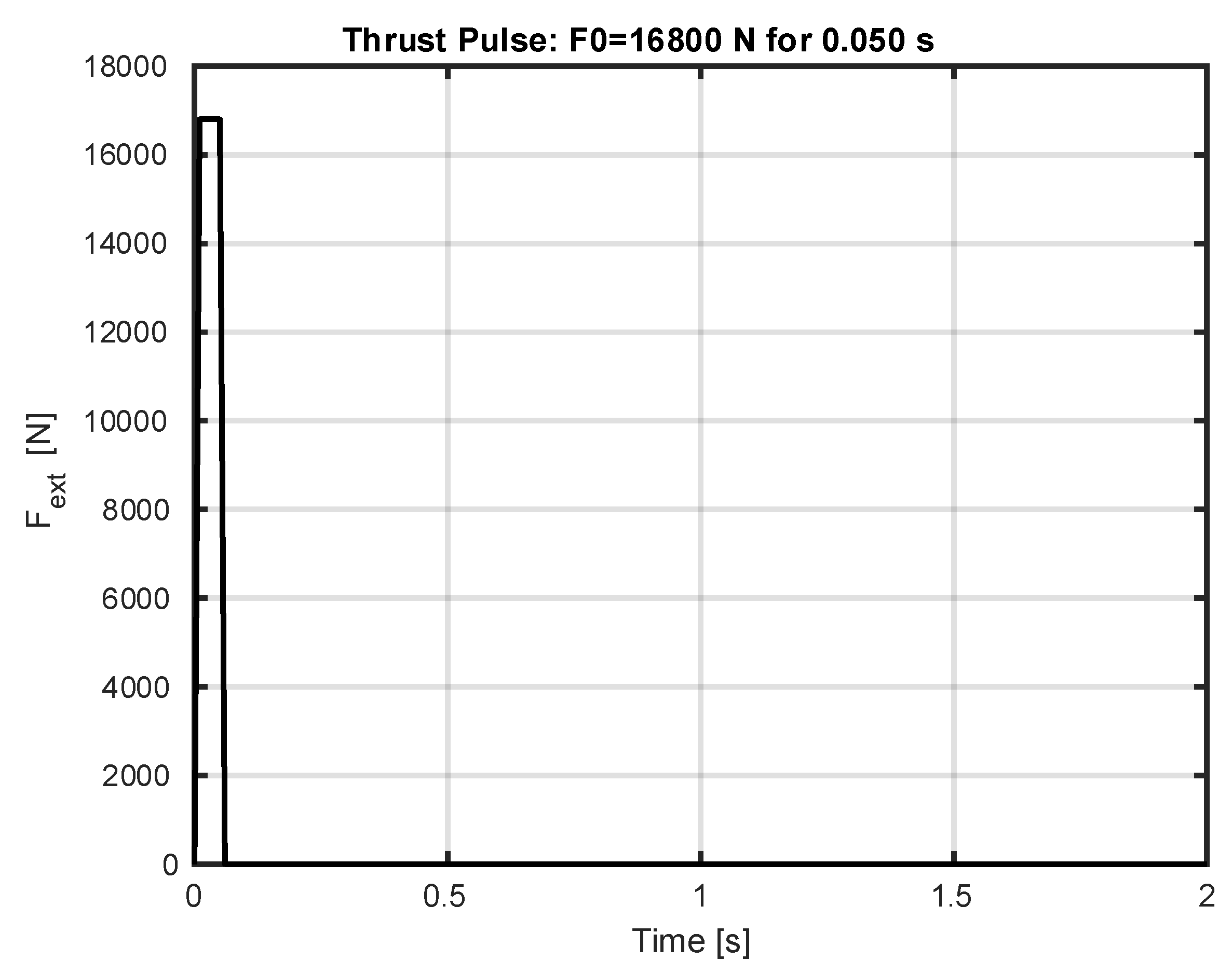
Figure 3.
Linear and angular displacements at pitch angle : (a) linear displacements in vertical direction when launcher pitch angle ; (b) angular displacements when launcher pitch angle .
Figure 3.
Linear and angular displacements at pitch angle : (a) linear displacements in vertical direction when launcher pitch angle ; (b) angular displacements when launcher pitch angle .
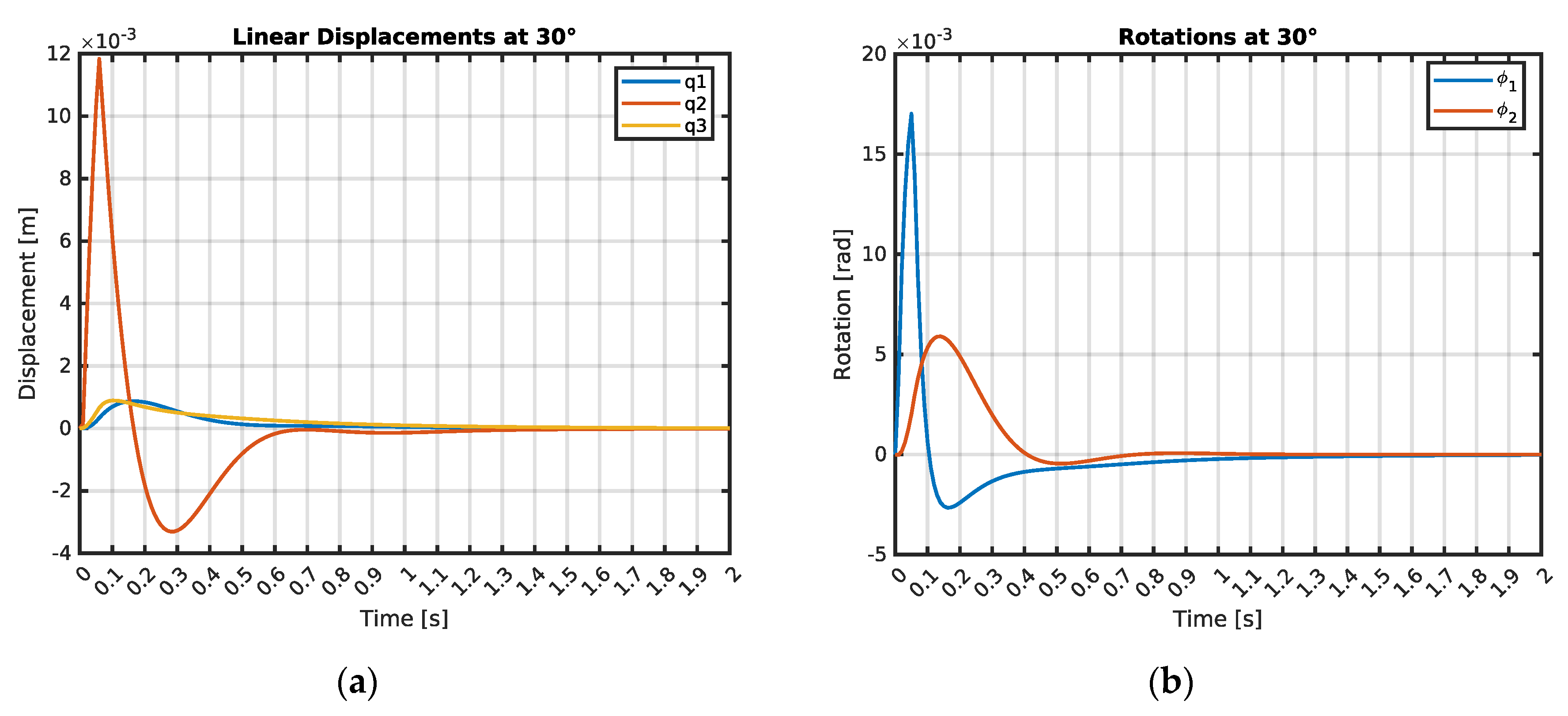
Figure 4.
Linear and angular displacements at pitch angle : (a) linear displacements in vertical direction when launcher pitch angle ; (b) angular displacements when launcher pitch angle .
Figure 4.
Linear and angular displacements at pitch angle : (a) linear displacements in vertical direction when launcher pitch angle ; (b) angular displacements when launcher pitch angle .
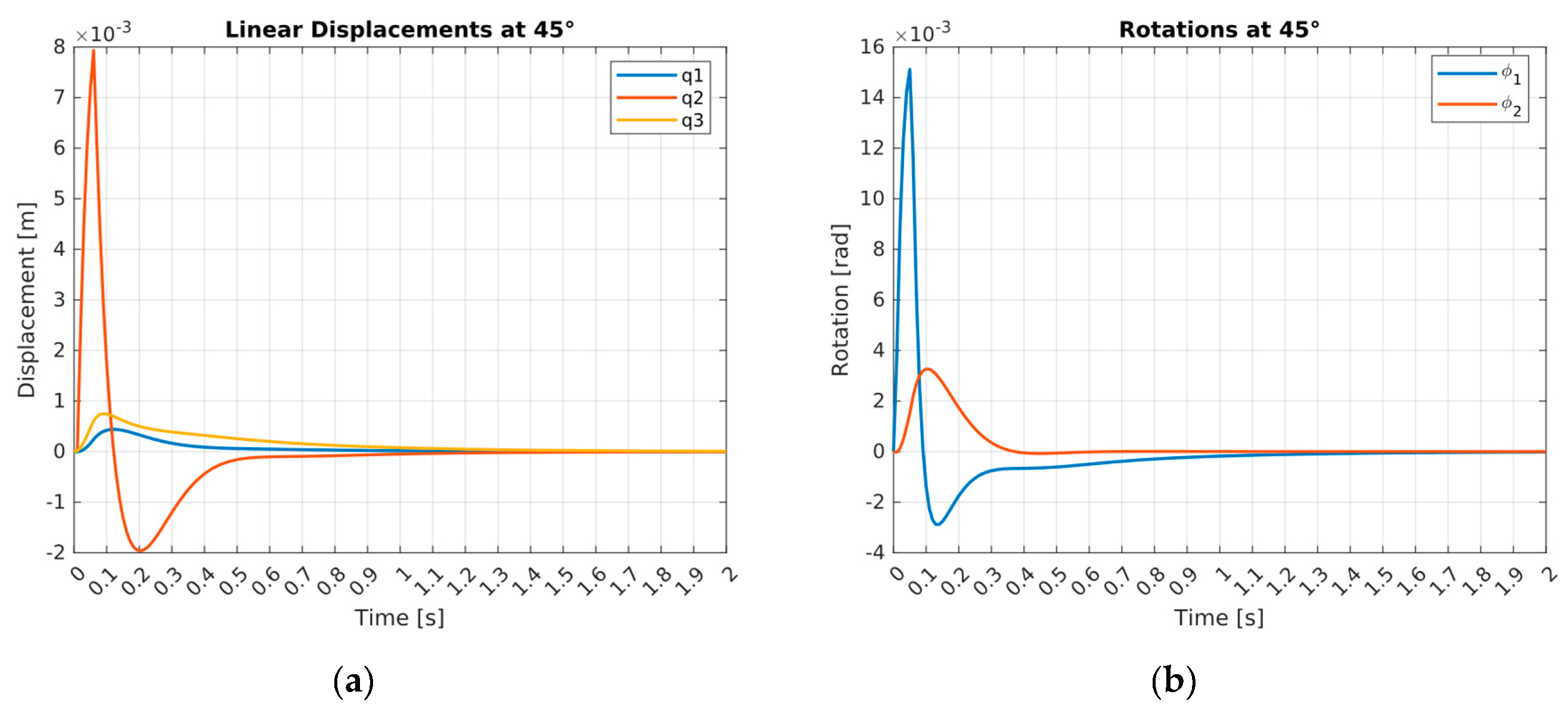
Figure 5.
Linear and angular displacements at pitch angle : (a) linear displacements in vertical direction when launcher pitch angle ; (b) angular displacements when launcher pitch angle .
Figure 5.
Linear and angular displacements at pitch angle : (a) linear displacements in vertical direction when launcher pitch angle ; (b) angular displacements when launcher pitch angle .
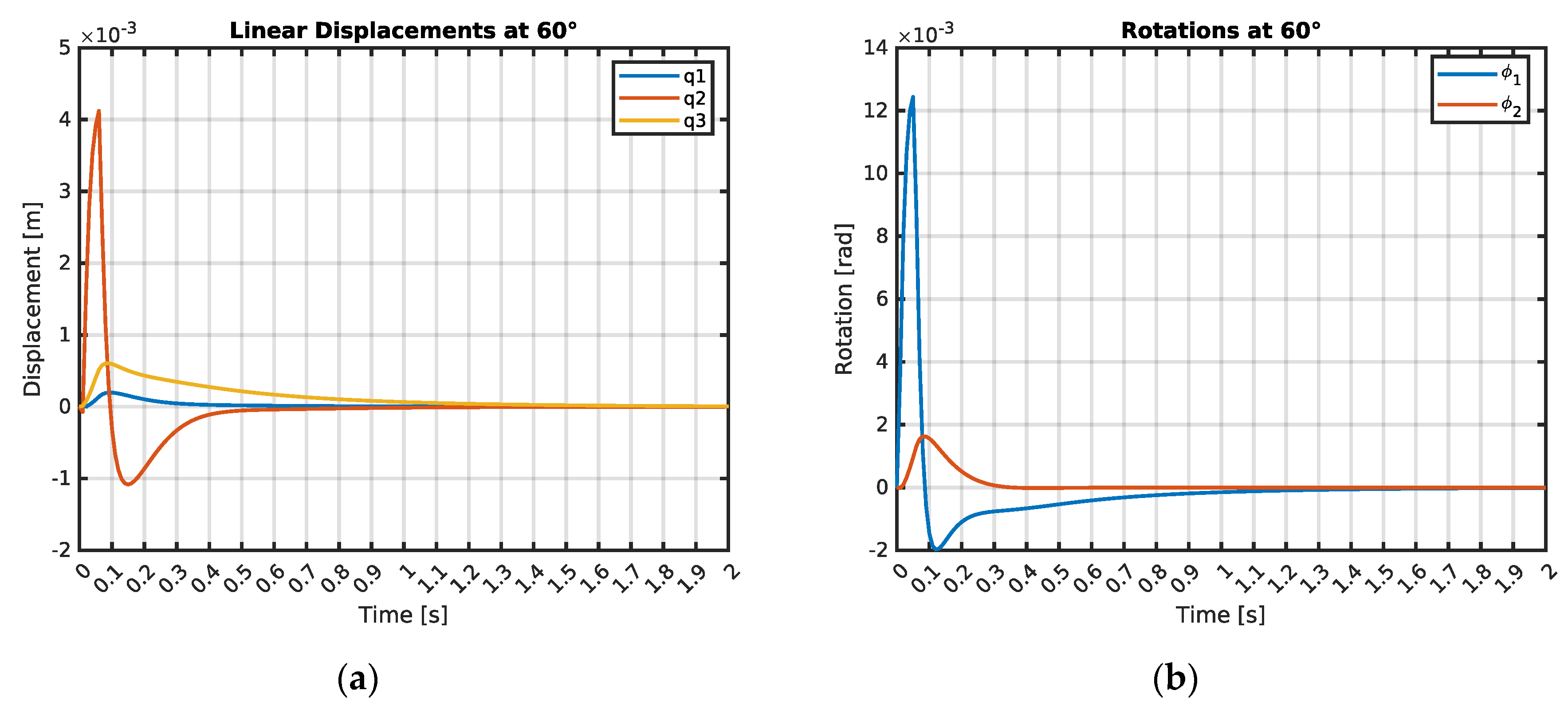
Figure 6.
Summary of linear velocities and accelerations results: (a) linear velocity when launcher pitch angle ; (b) linear acceleration when launcher pitch angle .
Figure 6.
Summary of linear velocities and accelerations results: (a) linear velocity when launcher pitch angle ; (b) linear acceleration when launcher pitch angle .
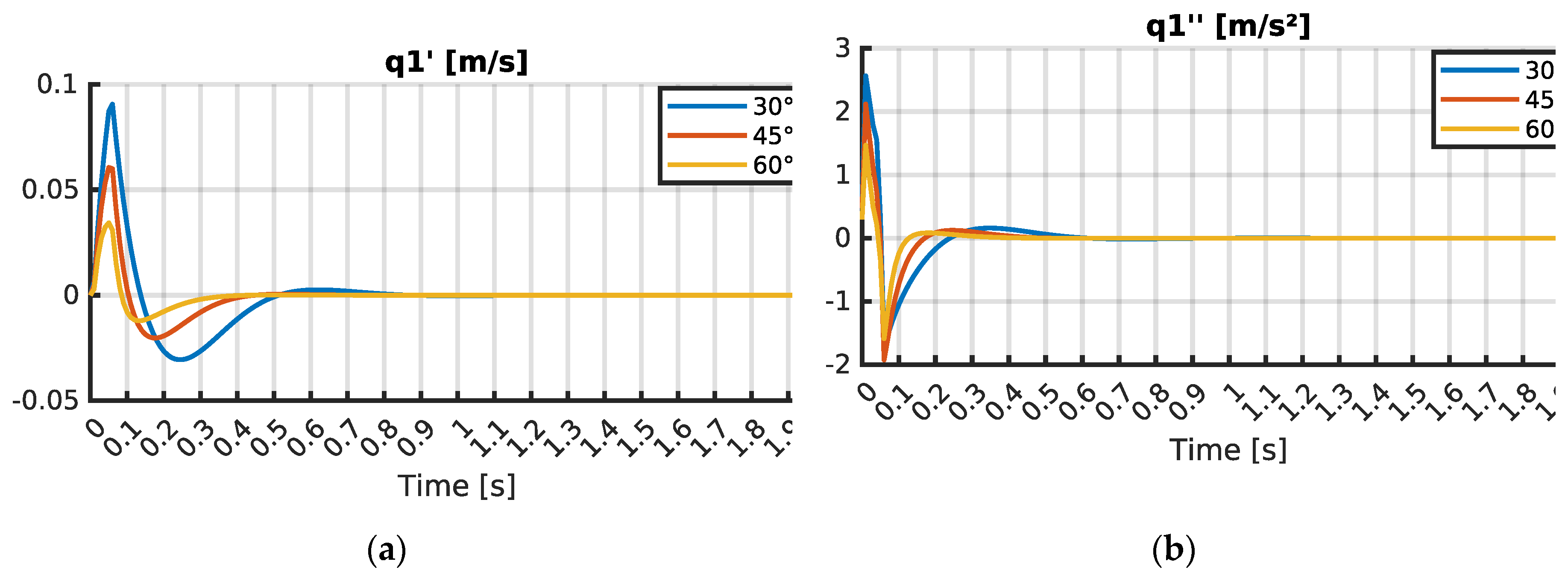
Figure 7.
Summary of linear velocities and accelerations results: (a) linear velocity when launcher pitch angle ; (b) linear acceleration when launcher pitch angle .
Figure 7.
Summary of linear velocities and accelerations results: (a) linear velocity when launcher pitch angle ; (b) linear acceleration when launcher pitch angle .
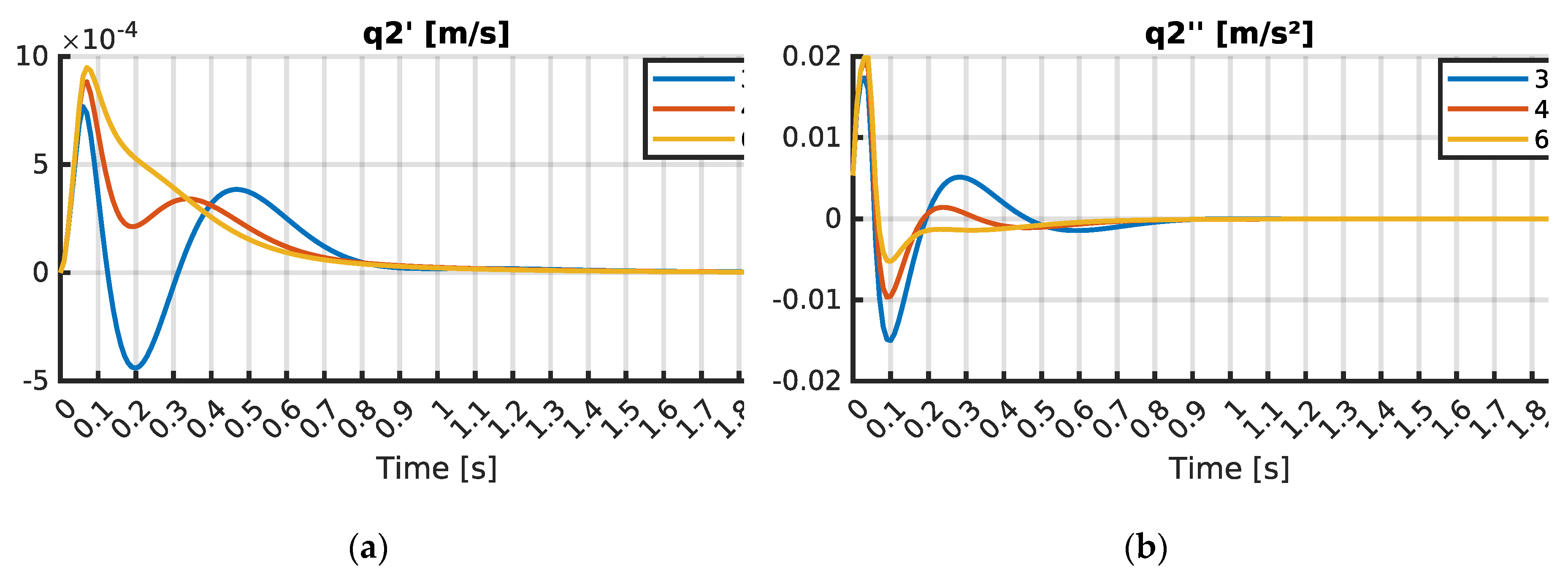
Figure 8.
Summary of linear velocities and accelerations results: (a) linear velocity when launcher pitch angle ; (b) linear acceleration when launcher pitch angle .
Figure 8.
Summary of linear velocities and accelerations results: (a) linear velocity when launcher pitch angle ; (b) linear acceleration when launcher pitch angle .
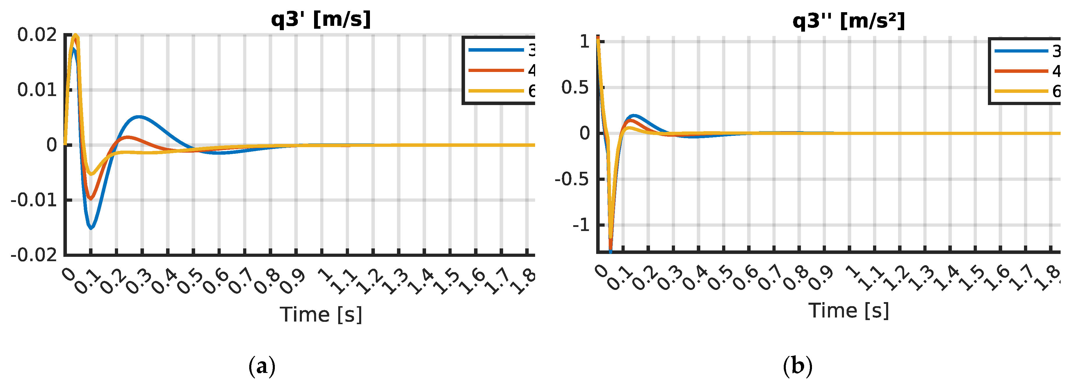
Figure 9.
Summary of angular velocities and accelerations results: (a) angular velocity when launcher pitch angle ; (b) angular acceleration when launcher pitch angle .
Figure 9.
Summary of angular velocities and accelerations results: (a) angular velocity when launcher pitch angle ; (b) angular acceleration when launcher pitch angle .
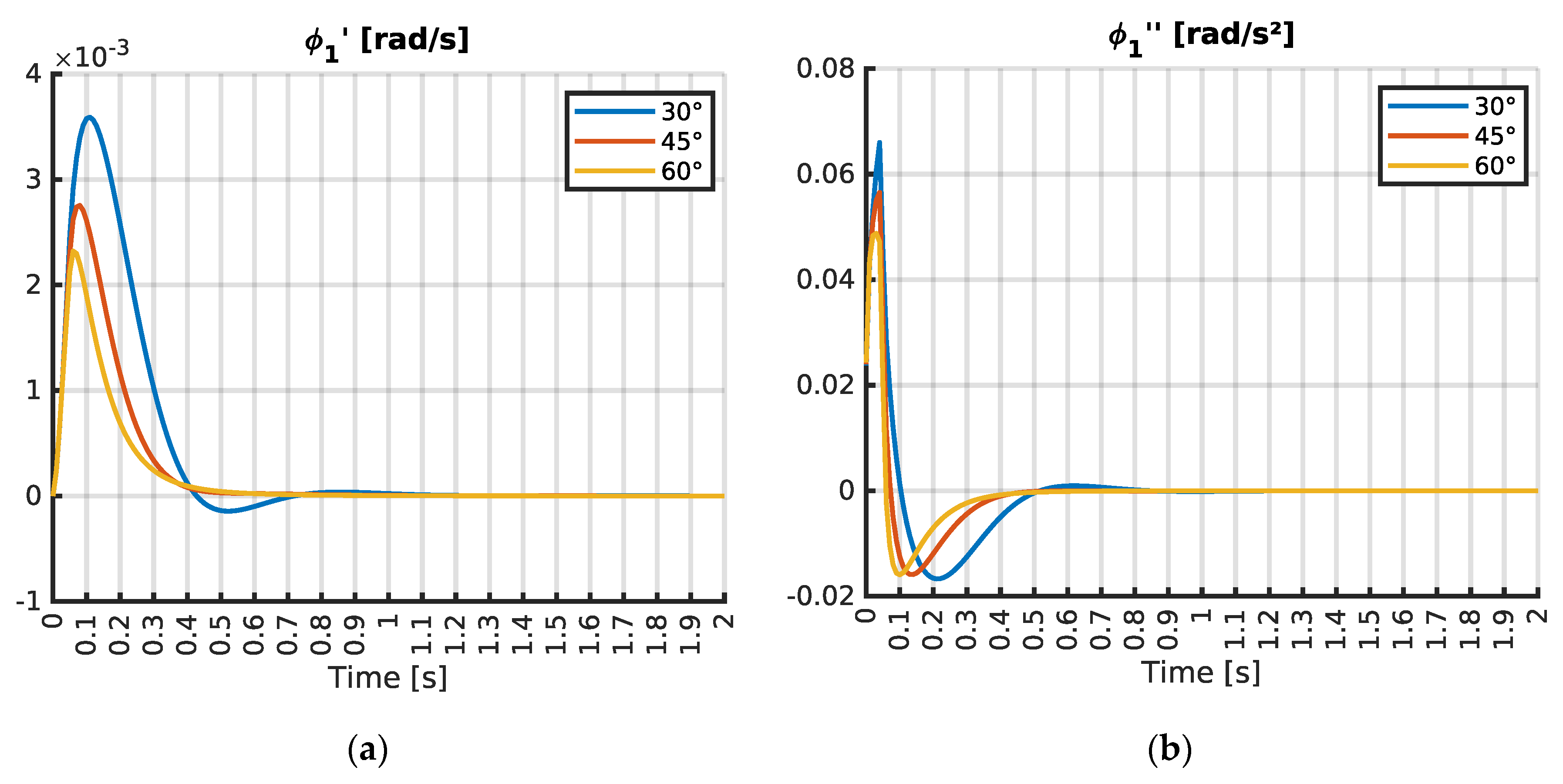
Figure 10.
Summary of angular velocities and accelerations results: (a) angular velocity when launcher pitch angle ; (b) angular acceleration when launcher pitch angle .
Figure 10.
Summary of angular velocities and accelerations results: (a) angular velocity when launcher pitch angle ; (b) angular acceleration when launcher pitch angle .
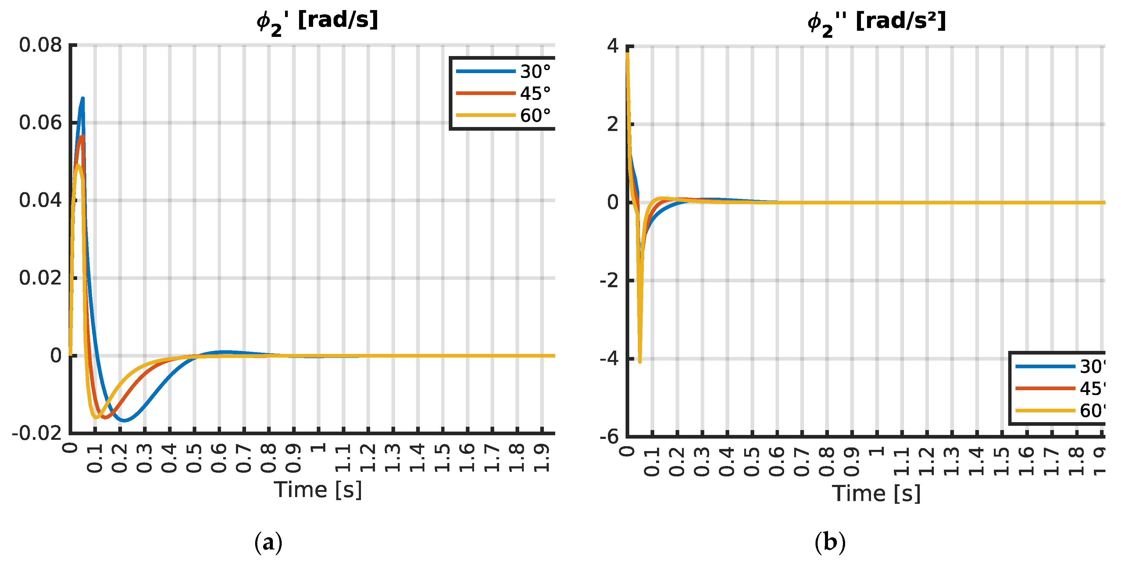

Table 1.
Vehicle-integrated air defense system parameters
| Description | Symbol | Units | Description | Symbol | Units |
|---|---|---|---|---|---|
| Rear unsprung mass of the HMMWV suspension and associated elements | kg | Distance from missile launchers’ revolution joint to its center of mass | m | ||
| Front unsprung mass of the HMMWV suspension and associated elements | kg | Total length of the HMMWV | m | ||
| HMMWV body sprung mass | kg | Vertical distance from missile launchers’ horizontal suspension mount attachment point to launchers’ center of mass | m | ||
| Missile launcher mass | kg | Mass linear displacement | m | ||
| Rear wheel tire stiffness coefficient | N/m | Mass linear displacement | m | ||
| Rear suspension stiffness coefficient | N/m | Mass linear displacement | m | ||
| Front wheel tire stiffness coefficient | N/m | Mass linear displacement | m/s | ||
| Front suspension stiffness coefficient | N/m | Mass linear displacement velocity | m/s | ||
| Missile launchers’ mount horizontal stiffness coefficient | N/m | Mass linear displacement velocity | m/s | ||
| Missile launchers’ mount vertical stiffness coefficient | N/m | Mass linear displacement acceleration | m/s2 | ||
| Rear wheel tire damping coefficient | Ns/m | Mass linear displacement acceleration | m/s2 | ||
| Rear suspension damping coefficient | Ns/m | Mass linear displacement acceleration | m/s2 | ||
| Front wheel tire damping coefficient | Ns/m | Mass angular displacement | rad | ||
| Front suspension damping coefficient | Ns/m | Mass angular displacement | rad | ||
| Missile launchers’ mount horizontal damping coefficient | Ns/m | Mass angular velocity | rad/s | ||
| Missile launchers’ mount vertical damping coefficient | Ns/m | Mass angular velocity | rad/s | ||
| Horizontal distance from rear suspension to vehicles’ center of mass | m | Mass angular acceleration | rad/s2 | ||
| Horizontal distance from front suspension to vehicles’ center of mass | m | Mass angular acceleration | rad/s2 | ||
| Horizontal distance from missile launchers’ vertical suspension mount point to vehicles’ center of mass | m | HMMWV moment of inertia | kg · m2 | ||
| Horizontal distance from missile launchers’ revolution joint attachment to vehicles’ center of mass | m | Missile launchers’ moment of inertia about hinge point | kg · m2 | ||
| Distance from revolution joint attachment to missile launchers’ vertical suspension mount point | m | Missile launchers’ pitch angle | |||
| Missile launchers’ length | m | Missile launch first phase excitation force | N |
Table 2.
Simulation input parameters of the vehicle-integrated air defense system.
| Name of the parameter | Symbol | Value | Units |
| Excitation force | 16 800 | N | |
| Pitch angle | 30 | ||
| 45 | |||
| 60 | |||
| Mass | 350 | kg | |
| 300 | kg | ||
| 2200 | kg | ||
| 890 | kg | ||
| Moment of inertia | 6660 | kg · m2 | |
| 5787 | kg · m2 | ||
| Stiffness coefficient | 463 800 | N/m | |
| 163 800 | N/m | ||
| 463 800 | N/m | ||
| 163 800 | N/m | ||
| 2 000 000 | N/m | ||
| 2 000 000 | N/m | ||
| Damping coefficient | 205 000 | Ns/m | |
| 27 160 | Ns/m | ||
| 205 000 | Ns/m | ||
| 27 160 | Ns/m | ||
| 200 000 | Ns/m | ||
| 200 000 | Ns/m | ||
| Dimensions | 4.93 | m | |
| 0.157 | m | ||
| 3.143 | m | ||
| 0.314 | m | ||
| 0.157 | m | ||
| 2.08 | m | ||
| 3.70 | m | ||
| 2.55 | m | ||
| 0.314 | m |
Table 3.
, oscillations initiation and stabilization times at different pitch angles.
| Symbol | Launcher pitch angle θi | |||||
| 30˚ | 45˚ | 60˚ | ||||
| Oscillations initiation [s] |
Oscillations end [s] |
Oscillations initiation [s] |
Oscillations end [s] |
Oscillations initiation [s] |
Oscillations end [s] |
|
|
q1 q2 q3 |
0.040 | 0.550 | 0.050 | 0.370 | 0.060 | 0.200 |
| 0.010 | 1.120 | 0.020 | 0.620 | 0.020 | 0.410 | |
| 0.030 | 0.990 | 0.030 | 0.880 | 0.030 | 0.810 | |
| φ1 | 0.010 | 1.350 | 0.010 | 1.250 | 0.010 | 1.170 |
| φ2 | 0.020 | 0.680 | 0.020 | 0.340 | 0.030 | 0.280 |
Table 4.
Variation of peak linear and angular displacement values.
| Symbol | Launcher pitch angle θi | Units | ||
| 30˚ | 45˚ | 60˚ | ||
|
q1 q2 q3 |
0.0009 | 0.0004 | 0.0002 | m |
| 0.0118 | 0.0079 | 0.0041 | ||
| 0.0009 | 0.0008 | 0.0006 | ||
| 0.01702 | 0.01511 | 0.01244 | rad | |
| 0.00590 | 0.00327 | 0.00163 | ||
Table 5.
, oscillations initiation and stabilization times at different pitch angles.
| Symbol | Launcher pitch angle θi | |||||
| 30˚ | 45˚ | 60˚ | ||||
| Oscillations initiation [s] |
Oscillations end [s] |
Oscillations initiation [s] |
Oscillations end [s] |
Oscillations initiation [s] |
Oscillations end [s] |
|
| 0.010 | 1.160 | 0.010 | 0.690 | 0.010 | 0.410 | |
| 0.020 | 0.720 | 0.020 | 0.630 | 0.020 | 0.580 | |
| 0.010 | 0.900 | 0.010 | 0.890 | 0.010 | 0.870 | |
| 0.000 | 1.340 | 0.000 | 1.010 | 0.000 | 0.770 | |
| 0.000 | 0.890 | 0.000 | 0.880 | 0.000 | 0.860 | |
| 0.000 | 1.240 | 0.000 | 1.190 | 0.000 | 1.160 | |
Table 6.
Variation of peak linear velocity and acceleration values.
| Symbol | Launcher pitch angle θi | Units | ||
| 30˚ | 45˚ | 60˚ | ||
| 0.0906 | 0.0606 | 0.0343 | m/s | |
| 0.0008 | 0.0009 | 0.0009 | ||
| 0.0175 | 0.0192 | 0.0200 | ||
| 2.5666 | 2.1201 | 1.5893 | m/s2 | |
| 0.0174 | 0.0193 | 0.0199 | ||
| 1.2956 | 1.2528 | 1.1279 | ||
Table 7.
, oscillations initiation and stabilization times at different pitch angles.
| Symbol | Launcher pitch angle θi | |||||
| 30˚ | 45˚ | 60˚ | ||||
| Oscillations initiation [s] |
Oscillations end [s] |
Oscillations initiation [s] |
Oscillations end [s] |
Oscillations initiation [s] |
Oscillations end [s] |
|
| 0.010 | 0.590 | 0.010 | 0.380 | 0.010 | 0.390 | |
| 0.010 | 1.070 | 0.010 | 0.520 | 0.010 | 0.630 | |
| 0.000 | 1.070 | 0.000 | 0.510 | 0.000 | 0.630 | |
| 0.000 | 1.310 | 0.000 | 0.990 | 0.000 | 0.890 | |
Table 8.
Variation of peak angular velocity and acceleration values.
| Symbol | Launcher pitch angle θi | Units | ||
| 30˚ | 45˚ | 60˚ | ||
| 0.00359 | 0.00275 | 0.00232 | rad/s | |
| 0.06632 | 0.05658 | 0.04902 | ||
| 0.06600 | 0.05652 | 0.04878 | rad/s2 | |
| 3.63792 | 3.82916 | 4.08081 | ||
Disclaimer/Publisher’s Note: The statements, opinions and data contained in all publications are solely those of the individual author(s) and contributor(s) and not of MDPI and/or the editor(s). MDPI and/or the editor(s) disclaim responsibility for any injury to people or property resulting from any ideas, methods, instructions or products referred to in the content. |
© 2025 by the authors. Licensee MDPI, Basel, Switzerland. This article is an open access article distributed under the terms and conditions of the Creative Commons Attribution (CC BY) license (https://creativecommons.org/licenses/by/4.0/).
Copyright: This open access article is published under a Creative Commons CC BY 4.0 license, which permit the free download, distribution, and reuse, provided that the author and preprint are cited in any reuse.


