
Submitted:
22 September 2025
Posted:
22 September 2025
You are already at the latest version
Abstract
Based on the characteristic mode theory, this paper proposes a low-profile metastructure circularly polarized broadband slot-coupled microstrip antenna. The metasurface is composed of 4*4 cut Angle metal patch, the antenna is fed by gap coupling, the floor gap is double trapezoidal connection. Based on the theory of characteristic mode, the function of degeneracy mode of square radiating patch is analyzed, and the degeneracy mode is separated effectively, which provides the mode basis for realizing circular polarization broadband performance. The size of the antenna is 0.67 λ×0.67 λ×0.043 λ, where λ is the free-space wavelength at 5.0 GHz. The simulation results show that the -10 dB impedance bandwidth is 29.8% for frequencies from 4.33 GHz to 5.82 GHz and the 3 dB axial ratio bandwidth is 17.8% for frequencies from 4.93 to 5.82 GHz. This antenna achieves good circularly polarised broadband performance and has excellent application prospects in areas such as satellite communications.
Keywords:
characteristic mode
; circular polarization (CP)
; metasurface (MTS)
; wideband
1. Introduction
The antenna is composed of metasurface composed of triangular elements and a slit floor, as well as microstrip lines. With the rapid development of wireless communication technology, especially in 5G and the upcoming 6G communication networks, efficient and compact antenna design [1][2] has become the key to ensuring communication quality and system capacity. Circularly polarized antennas play an important role in various wireless communications, satellite communications, radars and positioning systems because they can resist multipath effects and polarization mismatches. However, traditional circularly polarized antennas have the characteristics of narrow bands and high profiles, which will limit their application in the field of wireless communication. People have attempted to optimize the performance of circularly polarized broadband by adopting methods such as parasitic patches [3], adding air layers [4], multi-feed networks [5], and multi-layer patch structures [6]. However, these methods still have characteristics such as high contour structure and complex structure. The antenna proposed in literature [7] is fed with coplanar waveguide, this feeding method achieves a low profile while expanding the circularly polarized bandwidth, however, the radiation gain of this structure is very low.
Metasurfaces(MTS) are a type of two-dimensional material composed of a set of structural units, usually tiny metallic or dielectric components, and many researchers [8–10] have designed the shape, size, and arrangement of these units to improve the bandwidth and polarization properties of antennas. The MTS proposed in reference [8] consists of tangential square elements, achieving an impedance matching bandwidth(IBW) of -10 dB at 4.42-6.22 GHz and an Axial ratio(AR) bandwidth of 3dB at 4.60-5.72GHz. The MTS proposed in reference [9] adopts rectangular elements and achieves a 3 dB Axial ratio bandwidth(ARBW) of 3.75-4.85 GHz.The design of MTS enables these antennas to achieve circularly polarised broadband. However, the adoption of a dual-port power supply configuration resulted in a relatively complex overall structure. The complexity of these structures invariably increases the difficulty and cost of their manufacture. Moreover, despite the success of diverse methodologies in achieving specific outcomes, the ongoing challenge remains unresolved: the necessity to expand the operational frequency range while maintaining circular polarization performance, and to streamline the design.
This study proposes a design methodology for a circularly polarised broadband antenna based on MTS, using a slot-coupled microstrip feed approach. Its radiative layer is composed of multiple sub-wavelength metal patch units. By optimizing these non-periodically arranged units, effective control over the polarization state of electromagnetic waves is achieved. Despite the use of a non-periodic structure, this MTS design approach fully conforms to the core definition and design paradigm of metasurfaces [12][13][14]. First, the characteristic modes and surface currents of the MTS are analysed by characteristic mode theory, and the characteristic modes with mutually perpendicular modal current directions are selected as the working modes. Then, the positions of the ground plane slots are determined based on the distribution of the characteristic current intensity of the MTS. By designing the ground plane slots, the effective excitation of the working modes is achieved. Ultimately, this study can significantly improve the bandwidth and polarisation performance of the antenna while maintaining a compact structure. In addition, the professional electromagnetic simulation software CST is used for simulation experiments to ensure that the designed antenna has accurate experimental results.
2. Characteristic Mode Analysis (CMA)
In recent years, characteristic mode theory (CMT) has been used as a new and effective method for internal work mechanism analysis and MTS antenna design [15][16][17][18]. CMT decomposes the electromagnetic response of the structure into a set of basic characteristic modes.
By analysing each characteristic mode’s surface current, the MTS can be specifically designed. The surface current of an ideal conductor is defined as follows:
Jn are the N^{th} mode (n = 0,1,2,3,...), the characteristic currents in it. an is referred to as the modal excitation coefficient of the N^{th} characteristic mode. J is the total characteristic surface current. Modal Significance (MS) indicates the extent to which each characteristic current is easily excited and is related only to the conductor itself, rather than whether the conductor is excited or not. Pattern significance indicates the extent to which each characteristic current is easily excited. If MSn=1, it is in resonant mode; if MSn=0, it is in non-resonant mode. In general, the frequency range with MSn>0.707 is taken as the resonant frequency band. The MSn formula is as follows::
Normally, at least two modes are required to achieve CP radiation using feature modes. This means that two resonant modes should be excited within the same frequency band, each with a 90° phase difference [17], [18], or a feed structure should be used to obtain a 90° phase difference [15], [16]. In this paper, a feeder structure is chosen to realize CP radiation.
Figure 1.
Configuration of the MTS antenna. (a) Top view of the proposed MTS, (b) Floor gaps (c) Back view of microstrip line (d) Side view.
Figure 1.
Configuration of the MTS antenna. (a) Top view of the proposed MTS, (b) Floor gaps (c) Back view of microstrip line (d) Side view.
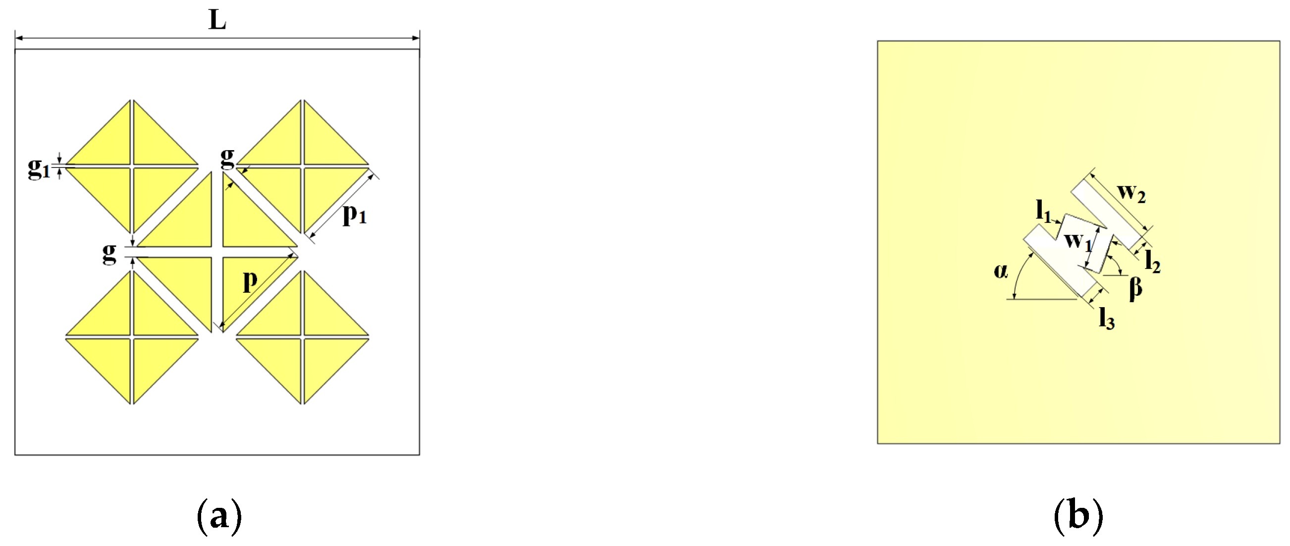
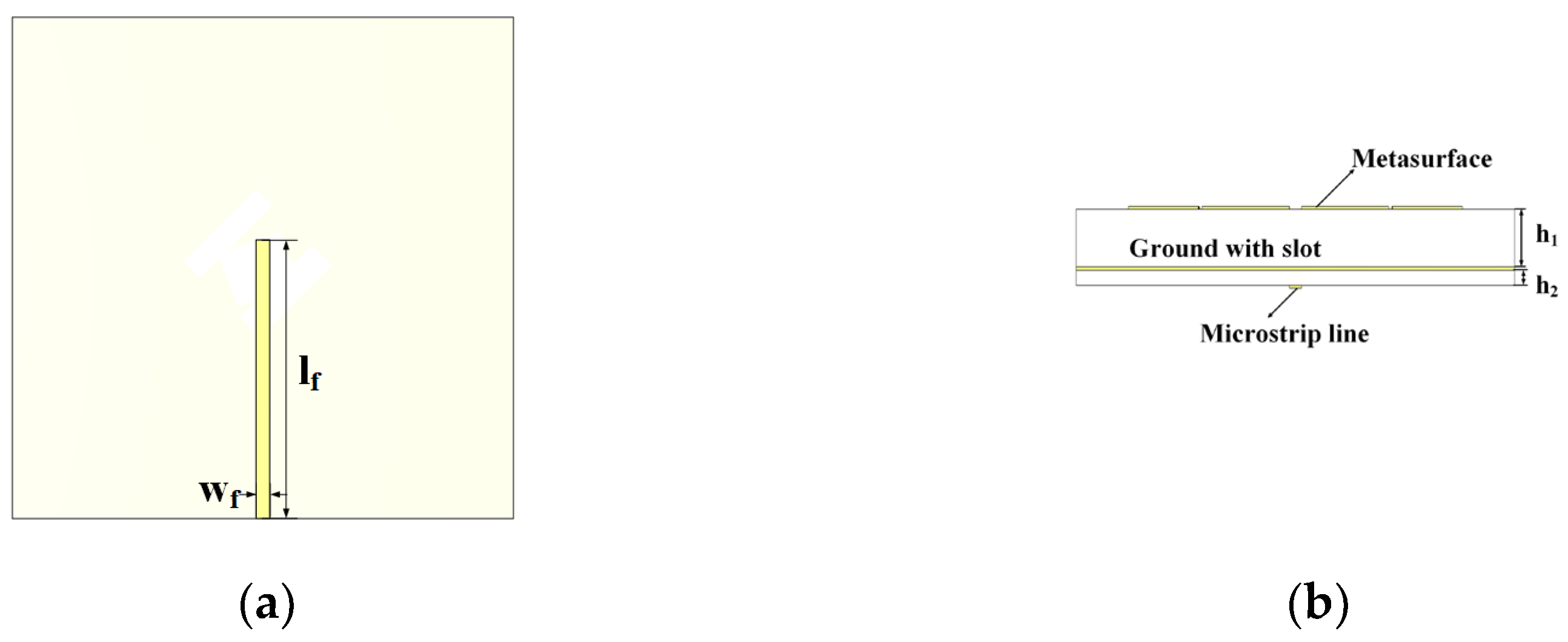
Figure 2.
(a)Initial MTS (b) The proposed MTS.
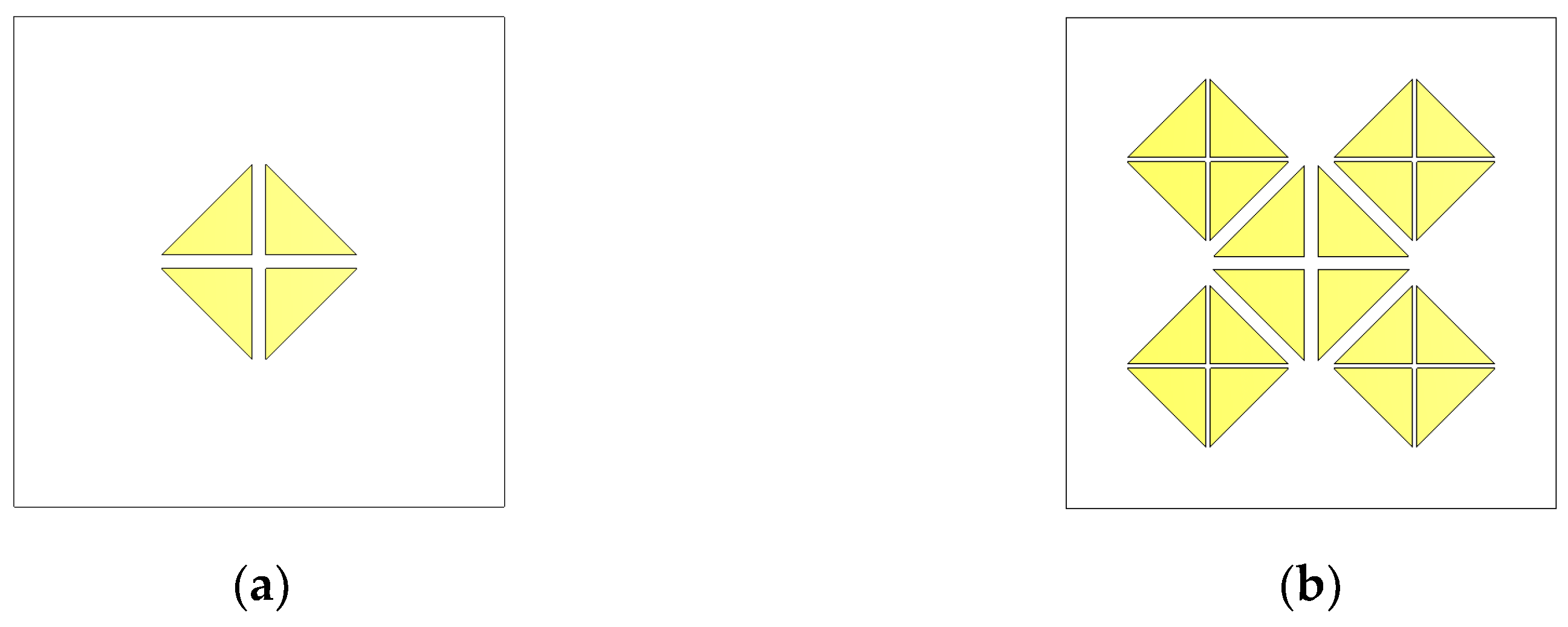
Figure 3.
Initial MTS current of the first four modes : (a) M1, (b) M2, (c) M3, (d) M4.
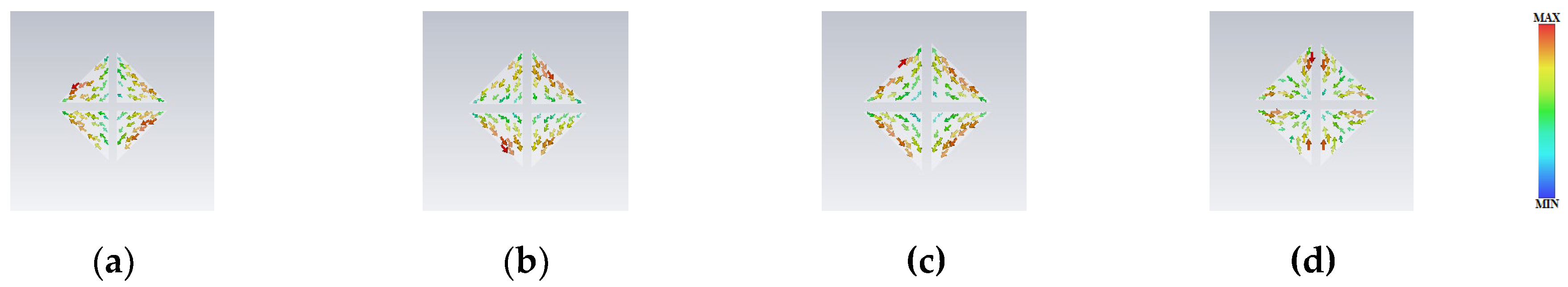
Figure 4.
The MTS Surface current of the first four modes : (a) M1, (b) M2, (c) M3, (d) M4.
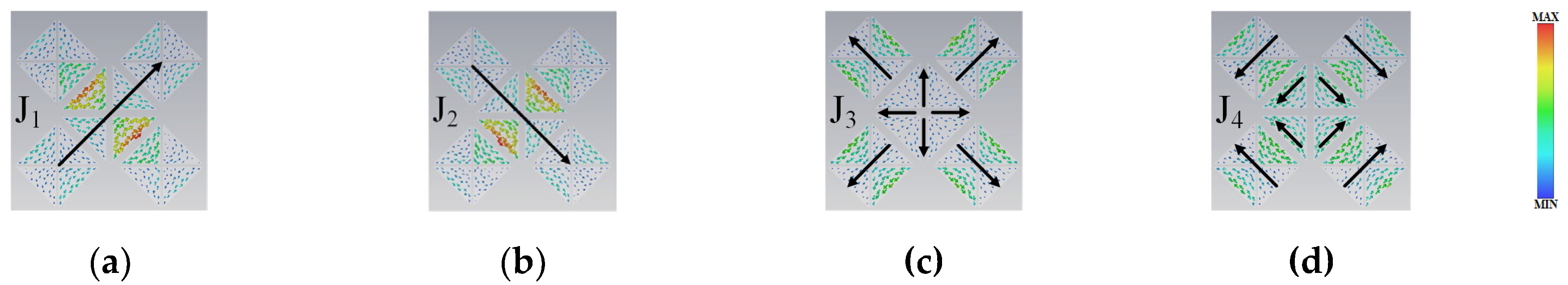
Figure 5.
The MTS three-dimensional radiation pattern of the first four modes : (a) M1, (b) M2, (c) M3, (d) M4.
Figure 5.
The MTS three-dimensional radiation pattern of the first four modes : (a) M1, (b) M2, (c) M3, (d) M4.
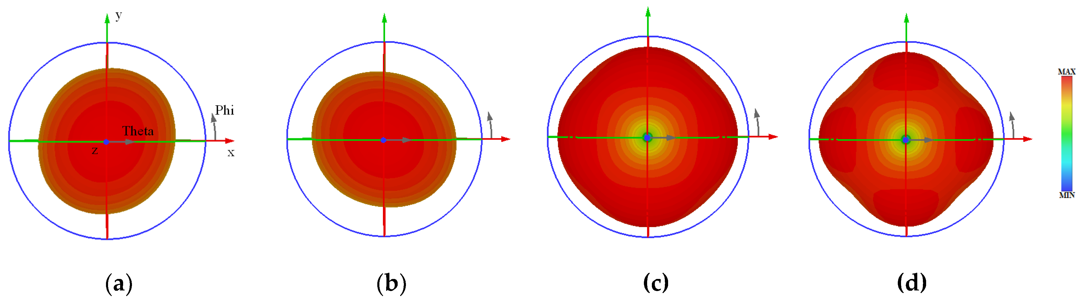
Figure 6.
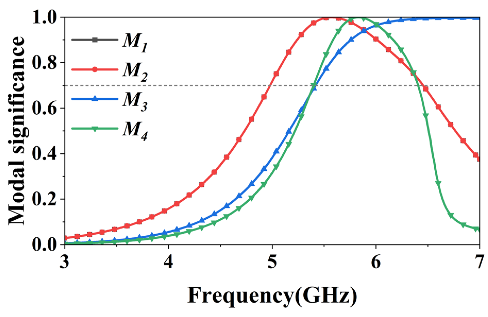
Modal significances of the proposed MTS.
3. Antenna Design
3.1. Design of MTS Based on Characteristic Modes
The overall structure of the antenna designed in this article is shown in Fig. 1. The upper and lower dielectric layers are made of Fr4 material with relative dielectric constant 4.4. First, the characteristic mode analysis of the MTS is performed using the CST simulation software.
As shown in Fig. 2(a), it is composed of four triangular patch units. The triangular units are sub-wavelength and are designed to achieve special electromagnetic characteristics. The overall structure and design purpose conform to the broad definition of MTS. Similarly, the patches in Fig. 2(b) add two-dimensional surrounding patches to the patches shown in Fig. 2(a), so this patch array also belongs to MTS.
First, an initial MTS as shown in Fig. 2(a) was designed. The surface current and three-dimensional radiation patterns of this MTS were analyzed to obtain the distribution of the MTS characteristic currents as shown in Fig. 3 and the three-dimensional radiation patterns of various modes as shown in Fig. 5. As shown the three-dimensional radiation diagram in Fig. 5, red represents high radiation intensity, and the lighter the colour, the lower the radiation intensity. It can clearly be seen that mode1(M1) and mode2(M2) have very high radiation intensities along the + Z axis (towards us), while M3 and M4 have very low radiation intensities along the + Z axis. In addition, the radiation directions of M1 and M2 point only towards the + Z axis, while those of mode3(M3) and mode4(M4) point in all directions. The radiation direction required in this study is exactly a single direction. However, as shown in Fig. 3, the current distribution positions of Modes 1 to 4 are very close to each other. This situation will cause great difficulties in designing the feed structure to excite the required modes (M1, M2). Therefore, as shown in Fig. 2(b), the patch designed in this paper is placed around the initial MTS to alter the current distribution of the characteristic pattern. Fig. 4 shows the mode current distribution of MTS after adding the parasitic patches.The mode currents J1 and J2 are in phase across the entire MTS, polarized along the +45° and −45° directions respectively. Their maximum current distributions concentrate at both the central patch and its edge areas. Both modes exhibit identical mode importance values [see Fig. 6] and orthogonal radiation patterns [see Fig. 5]. In contrast, mode currents J3 and J4 are out of phase, with their maximum currents distributed at the parasitic patches. Therefore, modes J1 and J2 are selected as candidates for generating CP radiation. It is clearly distinguishable that the surface current distributions of M1 and M2 remain on the initial MTS, while the current distributions of M3 and M4 are dispersed onto the surrounding patches, and the current intensity of the central patch is very small. Based on the above mode current analysis, the feed structure design in the central area of MTS can effectively stimulate M1 and M2, while reducing the interference of M3 and M4.
According to references [15] and [16], as shown in the Fig.6, the MS of M1and M2 overlap each other, i.e. these two modes form a pair of degenerate modes and a phase difference of 90 degrees between M1 and M2 is generated through the design of the feed to achieve circular polarization radiation. To achieve circularly polarised broadband by using two modes, it is required that the resonant frequencies of these two modes are similar, and a pair of degenerate modes is a very good choice. The MS curves of M1 and M2 are greater than 0.7, indicating a broadband above 1 GHz. This suggests that M1 and M2 can be easily excited in this frequency band to achieve broadband performance. The MS curves of M3 and M4 in the Fig.6 also show broadband characteristics. And the MS bandwidth of M1 and M2 overlaps with that of M3 and M4. Therefore, in the same frequency band, M1 and M2 can be excited, while M3 and M4 will cause interference, affecting the performance of the broadband generated by M1 and M2. However, through the analysis of the surface currents of the above four characteristic patterns, the design of the feed position at the center of MTS can effectively stimulate M1 and M2 while reducing the stimulation of M3 and M4. The following is the design of the feed structure to achieve this purpose.
Surface current analysis of MTS according to the above, the feeding structure must feed the MTS centre in order to excite M1 and M2 and suppress M3 and M4. In this paper, the gap coupling feeding method is chosen for feeding. This feeding method can excite the MTS well and ensure the radiation gain of the antenna. And the shape of the gaps on the ground determines the excitation effect for MTS.

Table 1.
This is a table. Tables should be placed in the main text near to the first time they are cited.Dimensions of the optimized antenna structure.(unit: mm).
Table 1.
This is a table. Tables should be placed in the main text near to the first time they are cited.Dimensions of the optimized antenna structure.(unit: mm).
| parameters | numerical value | parameters | numerical value |
| L | 54 | W2 | 6 |
| h1 | 4 | W2 | 11 |
| H2 | 0.5 | L1 | 6 |
| p | 10 | L2 | 2.5 |
| P1 | 8.6 | wf | 1.5 |
| g | 1.5 | lf | 30 |
| G1 | 0.5 | α | 45° |
| W1 | 6 | β | 70° |
Figure 7.
Effect of rotated angle α on (a) S11 and (b) AR.
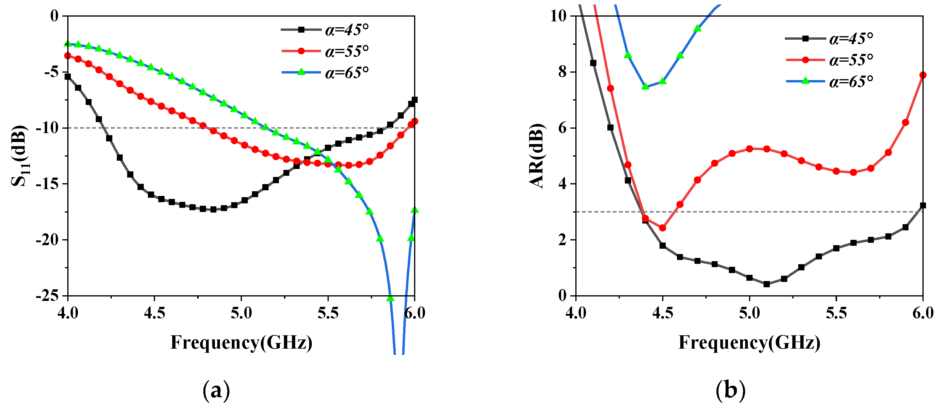
Figure 8.
Effect of rotated angle β on (a) S11 and (b) AR.

3.1. Design of Feed Structure
As shown in Figure 1(b), the floor gap consists of three rectangular sections: a central rectangular gap and two parallel rectangular gaps surrounding it. α represents the angle between the two parallel rectangular gaps and the horizontal line, while β denotes the angle between the central gap and the horizontal line. By adjusting α, the impedance matching bandwidth and circular polarization bandwidth performance of the antenna can be effectively adjusted. The overall parameters of the antenna are given in Table 1. As shown in Fig. 7(a), as α increases, the IBW also increases. It is observed in Fig. 7(b) that only α=45° achieves the ARBW.
Another parameter of the floor gap that greatly affects the impedance and 3 dB ARBW is the rotation Angle of central rectangular gap β, as illustrated in Fig. 8. It is seen that a good impedance and 3 dB AR bandwidths can beobtained by adjusting β to 70°.
It can be seen that the operation of rotating the central rectangular gap effectively improves the impedance and the circular polarisation performance of the antenna.
Figure 9.
Photographs of the fabricated antenna sample.(a) Front view. (b) Back view.
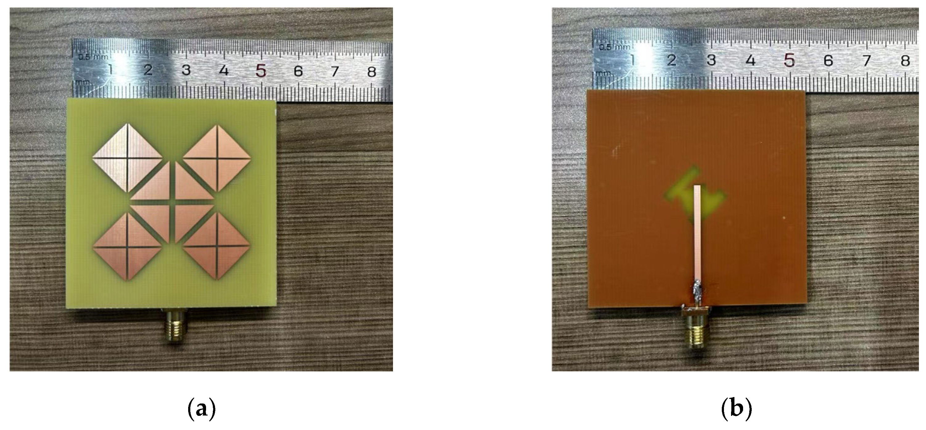
Figure 10.
(a) reflection coefficient (S11), (b) AR, (c) Gain.
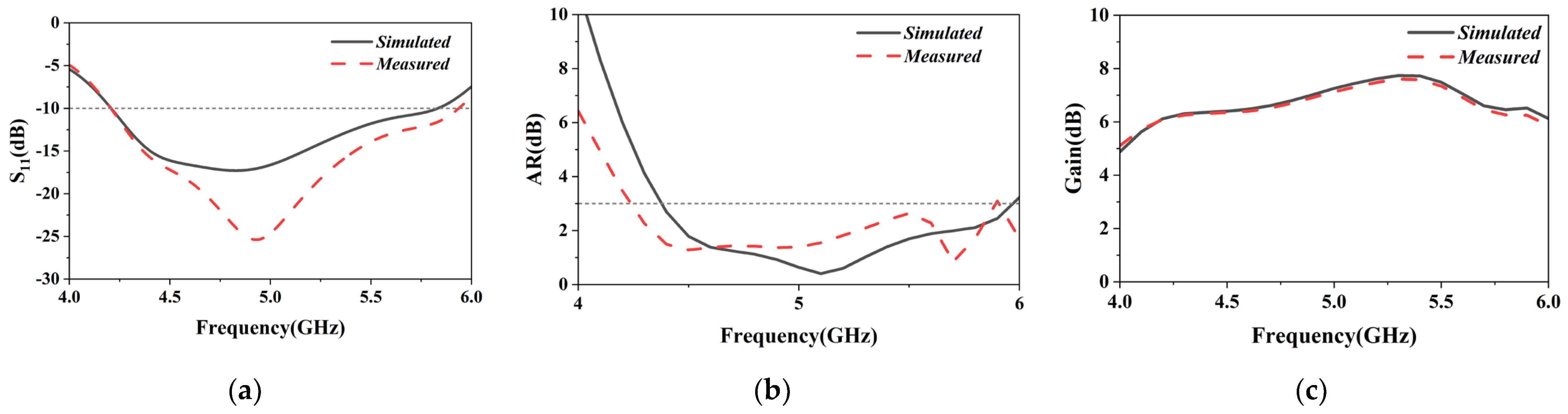
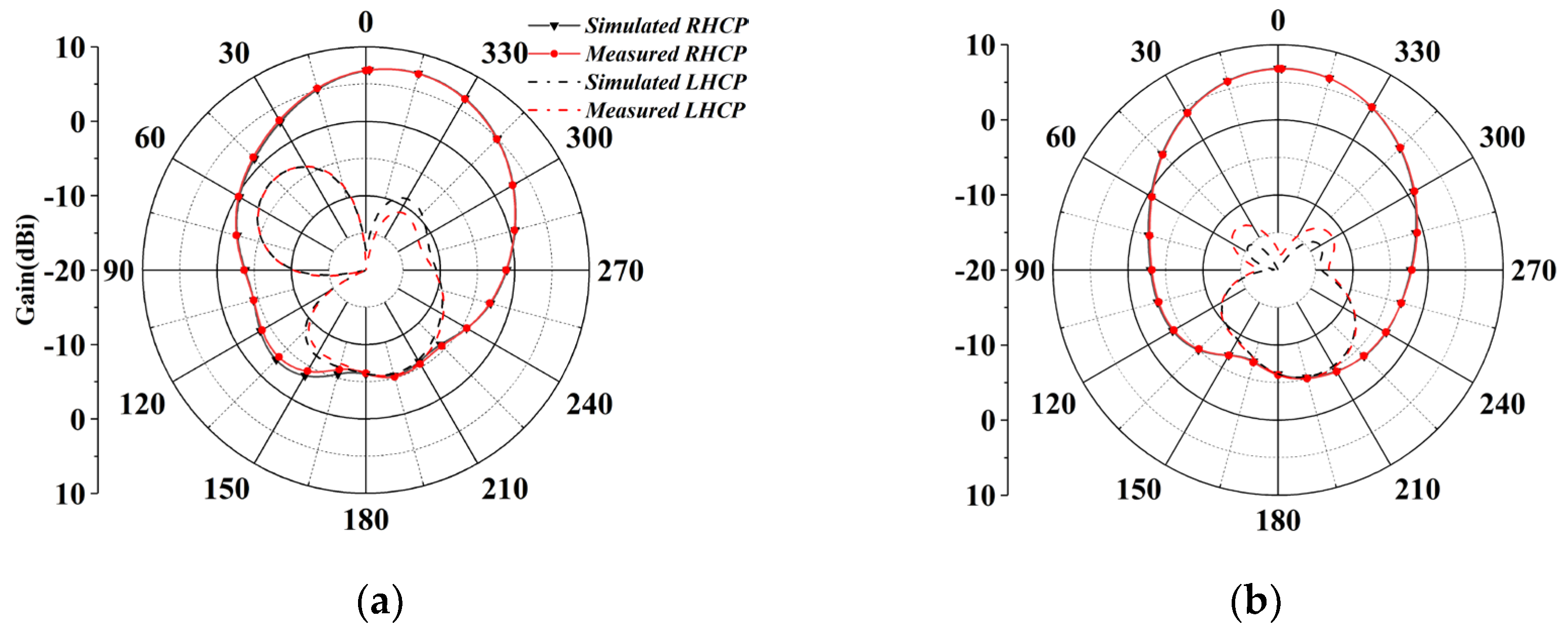
Figure 11.
Radiation patterns of the proposed MTS antenna(a) E plane and (b) H plane at 5GHz.
4. Time Domain Simulation Result
4.1. Experimental Simulation Results
In order to verify the feasibility of the simulation, a prototype of the MTS antenna was fabricated and actual measurements were taken. Fig. 9 shows a photograph of the fabricated antenna including two layers of FR-4 dielectric plates for the MTS and the feed structure, with the MTS copper side on the top surface, the middle surface of the two dielectric plates for the floor slit structure, and the microstrip line on the bottom surface.
The simulation and measurement results of the proposed MTS antenna are shown in Fig. 10.The S-parameter is used to measure the impedance matching bandwidth, and the results of the S-parameter can be measured using a vector network analyser. The simulation result of the S-parameter bandwidth of this antenna -10dB is 4.20~5.83 GHz, with a relative bandwidth of 33.4%, and the actual measured IBW is basically consistent with the simulation result. The processing and measurement errors will lead to a slight shift between the measured and simulated results. The axial ratio bandwidth is a measure of circularly polarised bandwidth, and a bandwidth of less than 3 dB is generally regarded as circularly polarised bandwidth. Fig. 10(b) shows the comparison between the measured and simulated results of the 3 dB axial ratio bandwidth of the antenna. Fig. 11 shows the comparison between the measured and simulated results of the antenna's left circularly polarized (LHCP) and right circularly polarized (RHCP) three-dimensional radiation maps for the E-plane and H-plane at the centre frequency of 5 GHz, which shows that the antenna is circularly polarized as RHCP and the radiation direction is concentrated in the +Z axis, which is in line with the expected radiation performance. The measured results are basically consistent with the simulation results, which verifies the feasibility of the antenna design.
Table 1.
Comparison of antenna performance with literature.
| Ref. | Sizes(λn3) | IBW(%) | ARBW(%) | Peak Gain (dBi) |
| [7] | 0.15×0.15×0.1 | 47 | 34.7 | 3.4 |
| [8] | 1.4×1.4×0.69 | 36 | 22.4 | 11.2 |
| [9] | 1.12×0.86×0.69 | 31 | 25.6 | 7.4 |
| [10] | 0.88×0.88×0.6 | 38.4 | 38.4 | 7.7 |
| [11] | 0.38×0.38×0.66 | 15.7 | 11 | 5.5 |
| [17] | 1.5×1.5×0.61 | 38.8 | 14.3 | 9.4 |
| [18] | 0.24×0.24×0.115 | 21 | 21 | 7.4 |
| Prop. | 0.9×0.9×0.76 | 33.4 | 32.8 | 7.6 |
4.2. Comparative Analysis of CP Antenna
The performance comparison between the antenna designed in this paper and the antenna in the reference literature is presented in Table 2. The antenna proposed in Reference [7] is very small in size and wide in bandwidth, but its gain is lower than that of the antenna proposed in this paper and its operating frequency is not the C-band commonly used in satellite communication. The operating frequencies of these antennas proposed in references [8–10] are relatively close to those proposed in this paper, all in the C-band. The antenna proposed in Reference [8] has a high gain but a large size, which will lead to an increase in cost. The antenna proposed in reference [9] has a similar gain to that in this paper but a relatively large size. The antenna proposed in Reference [10] has excellent performance and a relatively small size, which is similar to the performance in this paper. The antenna proposed in references [11] is very small in size, but its impedance matching bandwidth and circular polarization bandwidth are much narrower than those of the antenna proposed in this paper. Overall, the performance of the antenna proposed in this paper has certain advantages among these antennas. References [17,18] also employed CMA for antenna design. Compared with these two antennas, the antenna proposed in this paper has a significant advantage in circular polarization broadband performance.
3. Conclusions
This paper proposes a MTS slit coupling feed antenna. The MTS is a brand new structure composed of triangular elements, and the mode analysis is performed by CMT, and the mode to be excited is selected based on the MS curve and three-dimensional radiation map. Then, the feeding position at the centre of the MTS is determined based on the characteristic current distribution of the MTS. Finally, a novel floor-gap feeding structure was set up and the microstrip feeding method was adopted. Time domain simulation was then performed to achieve good impedance matching and circularly polarised broadband performance. This antenna is designed for MTS, which provides a good solution for the design of circularly polarised antennas and the realisation of the design of MTS excitation-gap coupling feeding structure. In the field of wireless communication, the antenna proposed in this paper has good application scenarios.
Author Contributions
All authors have read and agreed to the published version of the manuscript.
Funding
This research was funded by the doctoral research startup fund of Northeast Electric Power University, and project number is BSIXM-2021207. This paper was funded by the National Natural Science Foundation of China (61803356).
Data Availability Statement
The data presented in this study are available in the article.
Conflicts of Interest
The authors declare no conflicts of interest. The funders had no role in the design of the study; in the collection, analyses, or interpretation of data; in the writing of the manuscript; or in the decision to publish the results.
Abbreviations
The following abbreviations are used in this manuscript:
| CP | circular polarization |
| MTS | metasurface |
| IBW | impedance matching bandwidth |
| ARBW | Axial ratio bandwidth |
References
- Fan, F.-F.; Chen, Q.-L.; Xu, Y.-X.; Zhao, X.-F.; Feng, J.-C.; Yan, Z.-H. A wideband compact printed dipole antenna array with SICL feeding network for 5G application. IEEE Antennas Wirel. Propag. Lett. 2022, 22, 283–287. [Google Scholar] [CrossRef]
- Nie, L.Y.; Lau, B.K.; Xiang, S.; Aliakbari, H.; Wang, B.; Lin, X.Q. Wideband design of a compact monopole-like circular patch antenna using modal analysis. IEEE Antennas Wirel. Propag. Lett. 2021, 20, 918–922. [Google Scholar] [CrossRef]
- Tang, X.; He, Y.; Feng, B. Design of a wideband circularly polarized strip-helical antenna with a parasitic patch. IEEE Access 2016, 4, 7728–7735. [Google Scholar] [CrossRef]
- Liu, S.; Wu, W.; Fang, D.-G. Wideband monopole-like radiation pattern circular patch antenna with high gain and low cross-polarization. IEEE Trans. Antennas Propag. 2016, 64, 2042–2045. [Google Scholar] [CrossRef]
- Lin, C.; Zhang, F.-S.; Jiao, Y.-C.; Zhang, F.; Xue, X.J.I.A. A three-fed microstrip antenna for wideband circular polarization. 2010, 9, 359-362.
- Lin, C.; Zhang, F.-S.; Jiao, Y.-C.; Zhang, F.; Xue, X.J.I.A. A three-fed microstrip antenna for wideband circular polarization. 2010, 9, 359-362.
- Cao, R.; Yu, S.-C. Wideband compact CPW-fed circularly polarized antenna for universal UHF RFID reader. IEEE Trans. Antennas Propag. 2015, 63, 4148–4151. [Google Scholar] [CrossRef]
- Yang, W.; Meng, Q.; Che, W.; Gu, L.; Xue, Q. Low-profile wideband dual-circularly polarized metasurface antenna array with large beamwidth. IEEE Antennas Wirel. Propag. Lett. 2018, 17, 1613–1616. [Google Scholar] [CrossRef]
- Zeng, Y.; Qing, X.; Chia, M.Y.-W. A Wideband circularly polarized antenna with a nonuniform metasurface designed via multiobjective bayesian optimization. IEEE Antennas Wirel. Propag. Lett. 2024, 23, 1739–1743. [Google Scholar] [CrossRef]
- Wu, J.; Yang, W.; Gu, L.; Xue, Q.; Che, W. Low-profile wideband dual-circularly polarized metasurface antenna based on traveling-wave sequential feeding mechanism. IEEE Antennas Wirel. Propag. Lett. 2022, 21, 1085–1089. [Google Scholar] [CrossRef]
- Nasimuddin, *!!! REPLACE !!!*; Qing, X. Nasimuddin; Qing, X. A miniaturized wideband circularly polarized antenna using metasurface. In Proceedings of the 2022 16th European Conference on Antennas and Propagation (EuCAP). LOCATION Of Conference, SpainDATE Of Conference; pp. 1–5.
- Shang, S.; Tang, F.; Ye, X.; Li, Q.; Li, H.; Wu, J.; Wu, Y.; Chen, J.; Zhang, Z.; Yang, Y.; et al. High-efficiency metasurfaces with 2π phase control based on aperiodic dielectric nanoarrays. Nanomaterials 2020, 10, 250. [Google Scholar] [CrossRef] [PubMed]
- Choudhary, S.; Hiremath, K.R. Aperiodic Metasurface for Broadband RCS Reduction. In Proceedings of the 2020 URSI Regional Conference on Radio Science ( URSI-RCRS). LOCATION Of Conference, IndiaDATE Of Conference. 1–4.
- Zhang, Q.; Wan, X.; Liu, S.; Yin, J.Y.; Zhang, L.; Cui, T.J. Shaping electromagnetic waves using software-automatically-designed metasurfaces. Sci. Rep. 2017, 7, 3588. [Google Scholar] [CrossRef] [PubMed]
- Gao, X.; Tian, G.W.; Shou, Z.; Li, S.M. A Low-profile broadband circularly polarized patch antenna based on characteristic mode analysis. IEEE Antennas Wirel. Propag. Lett. 2020, 20, 214–218. [Google Scholar] [CrossRef]
- Liu, S.; Yang, D.; Pan, J. A low-profile broadband dual-circularly-polarized metasurface antenna. IEEE Antennas Wirel. Propag. Lett. 2019, 18, 1395–1399. [Google Scholar] [CrossRef]
- Zhao, C.; Wang, C.-F. Characteristic mode design of wide band circularly polarized patch antenna consisting of H-shaped unit cells. IEEE Access 2018, 6, 25292–25299. [Google Scholar] [CrossRef]
- Zeng, J.; Liang, X.; He, L.; Guan, F.; Lin, F.H.; Zi, J. Single-fed triple-mode wideband circularly polarized microstrip antennas using characteristic mode analysis. IEEE Trans. Antennas Propag. 2021, 70, 846–855. [Google Scholar] [CrossRef]
Disclaimer/Publisher’s Note: The statements, opinions and data contained in all publications are solely those of the individual author(s) and contributor(s) and not of MDPI and/or the editor(s). MDPI and/or the editor(s) disclaim responsibility for any injury to people or property resulting from any ideas, methods, instructions or products referred to in the content. |
© 2025 by the authors. Licensee MDPI, Basel, Switzerland. This article is an open access article distributed under the terms and conditions of the Creative Commons Attribution (CC BY) license (http://creativecommons.org/licenses/by/4.0/).
Copyright: This open access article is published under a Creative Commons CC BY 4.0 license, which permit the free download, distribution, and reuse, provided that the author and preprint are cited in any reuse.


