Submitted:
12 September 2025
Posted:
15 September 2025
You are already at the latest version
Abstract
This paper examines reinforced concrete (R/C) chimney type structures that have been used intensively after industrialization. Within the scope of the study, the differences between the Turkish Building Earthquake Code 2018 (TBEC-2018) and the Turkish Building Earthquake Code 2007 (TBEC-2007) and the innovations brought by the TBEC-2018 were investigated. A waste hot gas chimney at the Mersin Soda Factory, af-filiated with Şişecam A.Ş., was analyzed using the linear Modal Response Spectrum Method in Integrated Software for Structural Analysis and Design (SAP2000) soft-ware, preserving the existing sectional dimensions. The results of the analysis per-formed in the past of the structure using the Modal Response Spectrum Method ac-cording to the TBEC-2007 were compared with the results obtained from this study. The differences between the two codes were addressed in terms of linear calculation methods. As a result of the research, the modal analysis method was compared with similar sections only within the scope of linear calculation methods. Even in this case, it was observed that the forces and moments calculated according to the 2018 earth-quake code increased significantly compared to the 2007 earthquake code values.
Keywords:
industrial R/C chimneys
; seismic analysis
; Turkish Building Earthquake Code
; modal response spectrum method
; linear dynamic analysis
1. Introduction
Production operations in many industrial facilities and buildings produce significant amounts of waste and harmful gases. High altitudes are required to eliminate contact with the intended areas of use when disposing these gases. Structures constructed to meet these requirements are called "Industrial Chimneys".
With increasing population and industrialization, developing countries have seen rapid growth in industrial facilities and power plants to meet energy and production demands. However, this growth has also brought environmental concerns, where industrial chimneys play a vital role in mitigating pollution risks.
Historically, such chimneys were often constructed from masonry. Over time, the trend has shifted toward steel and reinforced concrete (R/C) due to better structural performance and durability. Given their height and slenderness, chimneys located in seismic zones must be carefully designed to withstand earthquake effects. Their unique geometry and mass distribution necessitate specialized analysis methods beyond typical building codes. Additionally, their foundations must integrate closely with the ground to maintain structural integrity.
This study focuses on the Waste Hot Gas Chimney at the Mersin Soda Factory, operated by Şişecam A.Ş. The chimney’s flue is insulated with firebrick and rock wool, standing at 130 m tall and supported by a circular raft foundation 18 m in diameter and 2 m thick. Linear seismic analysis was performed using Integrated Software for Structural Analysis and Design (SAP2000) software [1] with the Modal Response Spectrum Method, a linear dynamic approach defined in the Turkish Building Earthquake Code 2018 (TBEC-2018) [2]. The method, referred to as Mode Superposition with Response Spectrum Analysis in Section 4.8.2 of TBEC-2018 [2], was applied to evaluate seismic response. The analysis results, which were conducted according to the Turkish Building Earthquake Code 2007 (TBEC-2007) [3] before the construction of the structure in question, were taken from the Şişecam A.Ş. archive for comparison.
There are relatively few studies in the literature focused specifically on R/C industrial chimney structures. Therefore, this research holds significant original value by not only examining the updated TBEC-2018 [2] but also concentrating on a specialized building category—industrial chimneys. Additionally, this study contributes by performing a detailed comparison of TBEC-2018 [2] and the earlier TBEC-2007 [3] using linear dynamic calculation methods applied to a high-rise chimney structure. The following summarizes key studies that represent the current state of research in this area and provide important context for the present work:
Kareem and Hseih [4] conducted a reliability analysis of R/C chimneys under the influence of wind-induced loads. Parameters included concrete and reinforcement properties, structural dimensions, natural frequencies of the structure, and structural damping. Random variables were divided into three categories: wind environment meteorological data, parameters reflecting wind-structure interactions, and structural properties. The study showed that damping was the most significant contributor to the overall uncertainty in load effects.
Wilson [5] conducted tests on chimney specimens with varying height-to-depth ratios to develop nonlinear dynamic procedures for the analysis of chimneys. The tests provided valuable data for calibrating models that better reflect the complex dynamic behavior of tall, slender chimneys under earthquake excitation.
Huang et al. [6] analyzed a collapsed chimney via nonlinear methods and compared it with a similar chimney designed according to American standards. Using linear response spectrum analysis, they highlighted the importance of ductility by recommending multiple plastic hinges to distribute seismic damage rather than concentrating it at a single point, enhancing structural resilience.
Chmielewski et al. [7] investigated the theoretical and natural vibration frequencies and modes of an industrial chimney. They also presented an experimental investigation of the free vibration response using two geophone sensors. A comparison was made between the experimental and theoretical results. It was concluded that the natural periods and natural vibration modes of the chimney structure are significantly affected by the flexibility of the soil beneath the chimney foundation.
Huang and Gould [8] conducted a pushover analysis of R/C chimneys to investigate chimney response under dynamic loading. The investigation presents a 3D pushover analysis procedure . The study emphasizes the use of the proposed 3D pushover analysis for asymmetric structures because the structure will have different dynamic properties in different directions.
Öz [9] worked on the analysis of R/C chimneys using linear and nonlinear methods. In the design of R/C chimneys, the chimney body was considered according to the allowable stress method, but it was concluded that the chimney body should be calculated according to its bearing capacity because even a small increase in bending moment results in large increases in the tensile stresses of the reinforcement.
Şengün [10] conducted an analysis based on standards, the Model Code for Concrete Chimneys with Commentaries [11], ACI 307-08 [12], and Free-Standing Chimneys: General Requirements (BS EN 13084-1) [13], in effect at the time of his research, taking into account vertical, horizontal, and dead loads, as well as wind, earthquake, and temperature loads acting on chimneys and similar tall structures. The Calculation Values of Loads to be Taken in the Design of Structural Elements (TS 498) [14] was used for wind loads, and TBEC-2007 [3] was used for earthquake loads. The Model Code for Concrete Chimneys with Commentaries [11] and TBEC-2007 [3] were compared for earthquake loads. The comparison revealed that all the multipliers given by the Model Code for Concrete Chimneys with Commentaries [11] for equivalent earthquake loads were greater than those given by TBEC-2007 [3].
Elias et al. [15] investigated the effectiveness of mass dampers for multimodal control of retrofitted chimneys under seismic ground motion. The paper examined chimneys with geometrically regular and irregular features under cracked and uncracked conditions. An attempt was made to obtain optimal mass and damping ratios by locating the tuned mass damper where the chimney's mode shape amplitude was greatest. The research resulted in the reduction of peak displacement and improved seismic response control using tuned mass dampers.
Akniyazov [16] studied the effectiveness of vertical and horizontal corner reinforcement in R/C chimneys under vertical and lateral loads. Because diagonal reinforcement placement hinders the use of slipforms, the use of vertical and horizontal reinforcement as an alternative to diagonal steel reinforcement was analyzed. The results suggested a favorable alternative method.
Kılıç [17] presented a numerical model of a R/C chimney section similar to that in his past experimental studies. The outputs of the structure modeled were compared with the test results. It was found that the experimental study and the analysis were largely consistent.
Türkeli [18] worked on the interaction of the dynamic behavior of R/C chimneys with the ground and observed that the ground-structure interaction is an important element in the seismic behavior of R/C chimneys.
Bashir [19] conducted a comparative analysis of a R/C chimney constructed in the 1970s, evaluating its seismic and wind performance under different international and national design codes. The chimney was modeled based on its original dimensions, and the response spectrum method was used for seismic analysis. The study compared internal forces such as bending moments and stresses under various load combinations to determine the most critical design demands.
Küçük [20] compared the design and analysis of a multi-story R/C building according to DBYBYH [3] and TBEC-2018 [2] seismic codes. It was emphasized that the earthquake impact is addressed more realistically in TBEC-2018 [2], and that the use of effective section stiffness, the determination of spectral accelerations according to geographic coordinates, and the use of a strength excess coefficient contribute to this result.
Sarı [21] analyzed the seismic motions of an industrial chimney that collapsed during the Kocaeli earthquake in different soil types using the Analysis System: Engineering Simulation Software (ANSYS) [22] finite element program. The seismic characteristics of the structure (mode shapes and frequency), as well as the stresses, elastic and plastic movements, and displacements occurring in the structure, were obtained and compared.
Çaycı and Eldemir [23] studied the comparison of building performance levels defined under TBEC-2007 [3] and TBEC-2018 [2]. In this context, five existing buildings were modeled. It was observed that the cross-sectional damage limits of both codes differed significantly. The conclusion was that TBEC-2007 [3] fell short of the TBEC-2018 [2] criteria.
In his study, Çiçek [24] analyzed R/C chimneys of varying heights according to acceleration spectra defined in different standards. He examined the extent to which the variability in the spectrum affected the top displacements and shear forces at the foundation. It was observed that the increasing trends in the chimney tip displacements and the shear forces at the base were directly related to the first-mode percentage increase rates and provided sufficient results regarding the seismic performance of the chimney.
Alihassan [25] analyzed a 25-m-high industrial R/C chimney reinforced with 2 mm-thick glass fiber reinforced polymer (GFRP) fabric. The structure's frequencies and periods were examined. When the first mode of the structure was investigated, it was observed that the structure's period decreased by 2% between before and after the reinforcement. An increase of approximately 12-13% was also seen in the maximum moment and shear force values.
Elhıdır [26] investigated the statics of R/C chimneys to observe the effects of temperature changes. A 50-m-high chimney was modeled in SAP2000 software [1]. Maximum moments and stresses were examined for three different temperature values. It was observed that temperature had a negative, increasing effect. It was assessed that displacements and internal stresses increased significantly (approximately two-fold) with increasing temperature.
The aims of this research were to examine TBEC-2018 [2] in detail, to investigate the differences between TBEC-2018 [2] and TBEC-2007 [3] seismic codes and the innovations brought by TBEC-2018 [2], and to evaluate the differences of linear calculation methods within the scope of both seismic codes on an industrial chimney structure within the scope of the high-rise building class.
In parallel with these objectives, a comprehensive study was conducted on industrial chimney-type structures, including their types, sections, and history. The innovations introduced by TBEC-2018 [2], calculation steps for high-rise buildings, and the Modal Response Spectrum Method were discussed in detail. The design of an industrial chimney-type structure using the Modal Response Spectrum Method previously performed according to TBEC-2007 [3], and the analysis results obtained in this study according to TBEC-2018 [2] were examined in detail. In the analyses of the investigated structure, conducted according to TBEC-2018 [2] principles, the Turkish Standard - Design and Construction Rules for Reinforced Concrete Structures TS 500 [27] was utilized.
2. Analytical Study
2.1. Structural Overview
In the study, the waste gas chimney located in the Kazanlı location of the Mersin Soda Factory, which operates under the body of Şişecam A.Ş., was examined. A general view of the structure is shown in Figure 1.
The linear analysis results of the structure, conducted using the Modal Response Spectrum Method according to TBEC-2007 [3], was obtained from the archives of Şişecam A.Ş. Within the scope of comparing the linear method results in the high-rise building class, the Modal Response Spectrum Method was determined as the analysis method also in the analysis studies according to TBEC-2018 [2]. The chimney features are given below:
- • Height: 130 m;
- • Base outer diameter: 9.2 m, thickness: 40 cm;
- • Upper outer diameter: 7.2 m at 128 m and 4.2 m at 130 m, thickness: 20 cm;
- • Concrete quality: C30/70;
- Operating temperature: 130°C;
- Concrete unit weight: 2500 kg/m3;
- The chimney is considered as fixed from the bottom;
- Internally it is lined with a brick fire extinguishing chimney;
- Insulation: 10 cm rock wool;
- In the order of linear interpolation, the wall thickness and diameter change (decrease) from bottom to top;
- Equivalent surface roughness, for smooth concrete according to EN 1991-1-4 Table 7.13 [29];
- Internal concrete floors at 6 m, 9.6 m, 18 m, and above at intervals of 10 m (average radius of 1.45 m) and steel platforms covering 45° from the outer diameter radius;
- Steel platform of 360° at the height of 68 m;
- At the height of 6 m, the radius is 3.5 m.
2.2. Material Properties
- Concrete compressive strength: 27.5 MPa;
- Elasticity modulus of concrete : 25 GPa;
- Poisson ratio of concrete: 0.2;
- Unit volume weight of concrete: 2400 kg/m3;
- Yield strength of steel: 414 MPa;
- Tensile strength: 620 MPa;
- Modulus of elasticity of steel : 200 GPa;
- Unit volume weight of steel: 7750 kg/m3.
2.3. Loading Conditions
Loads considered include:
- Dead loads: self-weight of concrete, steel platforms, ladders, insulation (10 cm rock wool, , and fire brick lining (8 cm thickness,);
- Live loads: maintenance and operational loads;
2.3.1. Wind Load Calculation
According to TS 498 [14], the basic wind speed varies with height and is defined as:
- 28 m/s (0–8 m);
- 36 m/s (8–20 m);
- 42 m/s (20–100 m), and;
- 46 m/s (>100 m).
The characteristic wind speed was calculated using TS EN 1991-1-4 [30] according to Equation 1 as:
The mean wind speed at height , , was obtained from Equation 2:
with (flat terrain), and , where the terrain roughness was taken as 0.05 m for Terrain Category II.
The peak wind pressure was calculated using Equation 3:
where air density , and the turbulence intensity was calculated by Equation 4:
The external surface pressure acting on the chimney was found from Equation 5:
where , with coefficients obtained from EN 1991-1-4 [29] based on slenderness ratio , shape factor , and the Reynolds number , which governs the aerodynamic flow regime around the chimney.
Finally, the wind force acting along the chimney height was calculated using Equation 6:
where (structural factor), (force coefficient with end effect), is the projected area.
The wind pressure and resulting force increased with height, consistent with the chimney’s slenderness and exposure conditions. The detailed variation of , , and along the chimney height is presented in Table 1.
2.3.2. Seismic Load Calculation
The seismic design of the 130-m R/C chimney was carried out in accordance with the TBEC-2018 [2]. This code introduced significant changes compared to the previous TBEC-2007 [3] code, including revised site classification criteria, updated spectral acceleration coefficients, new performance-based design approaches, and more comprehensive provisions for tall and special structures.
The design earthquake ground motion level was taken as DD-2, representing a 475-year return period with a 10% probability of exceedance.
The seismic design parameters for the chimney were obtained from the official earthquake hazard map provided by the AFAD [31]. Based on the geographical location of the Mersin Soda Factory, the following seismic parameters were used:
- Soil class: ZE
- Short-period spectral acceleration coefficient: ;
- 1-second period spectral acceleration coefficient: ;
- Short-period design spectral acceleration coefficient: ;
- 1-second period design spectral acceleration coefficient: .
The structure was assigned a building importance factor of , representing a standard-risk industrial facility as specified in Table 3.1 of TBEC-2018 [2].
A structural system behavior factor and an overstrength coefficient were adopted, as specified in Table 6.1 of TBEC-2018 [2] for vertical cantilever-type R/C systems. These coefficients were used to reduce the elastic earthquake forces in accordance with the code's force reduction methodology, accounting for both energy dissipation capacity and system overstrength.
The classification of a high-rise building is generally based on its height, function, and structural characteristics. Although the chimney exceeds 100 m in height, it is not classified as a high-rise building in the conventional sense due to its industrial function and geometry. However, certain high-rise design principles defined for Building Height Class BYS = 1 were still considered, particularly with regard to dynamic amplification, displacement checks, and performance criteria.
The 130-m-tall R/C chimney examined in this research is categorized as an industrial structure and is treated as a special structure under TBEC-2018 [2], rather than as a conventional high-rise building. Therefore, the use of linear dynamic analysis via the Modal Response Spectrum Method is deemed appropriate. Reference data from an earlier analysis based on TBEC-2007 [3], conducted prior to construction, were obtained from the Şişecam A.Ş. archives.
The defined seismic parameters were implemented in the structural analysis using SAP2000 software [1], applying a Modal Response Spectrum Method, as specified in Section 4.8.2 of TBEC-2018 [2]. This method involves performing a modal analysis to determine the maximum modal responses in both the x and y directions, based on different natural vibration periods. The individual modal responses, such as displacements, internal forces, and relative story drifts, are calculated for each mode and then statistically combined to estimate the maximum structural response.
For each vibration mode , the maximum response in the x-direction is calculated by Equation 7:
where is the unit modal response quantity (e.g., displacement or internal force) in the x-direction, and is the reduced design spectral acceleration corresponding to the natural vibration period .
After obtaining the peak response values for each mode, these are statistically combined, typically using the SRSS (Square Root of the Sum of Squares) or CQC (Complete Quadratic Combination) methods, to calculate the total response of the structure. This process is repeated for each response quantity of interest.
To account for multidirectional ground motions, earthquake effects in the two horizontal directions (x and y) are combined according to Equations 8 and 9:
where and represent the design earthquake effects in the orthogonal horizontal directions, and is the resultant horizontal earthquake effect. In addition, the vertical seismic effect is considered separately where relevant. All seismic loads are evaluated in conjunction with the dead load , as required by the code.
This approach ensures that the combined effects of multiple vibration modes and earthquake directions are adequately captured in the design and performance assessment of the chimney structure.
2.4. Load Combinations
The structural design considered all relevant load combinations in accordance with TS 500 [27]. The combinations used in the chimney analysis are summarized below:
- Vertical loads only;
- 2.
- Wind load cases;
- 3.
- Seismic load cases;
- 4.
- Lateral soil pressure cases.
In these expressions, denotes the dead load, represents the live load, refers to deformation-related effects caused by temperature changes, shrinkage, and differential settlement, is the wind load, indicates the earthquake load, and corresponds to the lateral earth pressure.
For seismic load combinations, horizontal earthquake effects were applied in two orthogonal directions, with scale factors of 1.0 in the x-direction and 0.3 in the y-direction, as specified in TBEC-2018 [2].
2.5. Structural Modeling
The structural analysis of the chimney was conducted using the finite element software SAP2000 [1], employing a 3D linear elastic analysis approach. The chimney was modeled with four-node thin shell elements, suitable to the chimney’s slenderness and thin wall geometry. Each node has six degrees of freedom, enabling accurate representation of translational and rotational behavior. The geometry of the four-node thin shell element used in the analysis is illustrated in Figure 4, while Figure 5 presents a typical cross-sectional detail of the chimney wall.
A mesh size of 1.2 m × 2 m was used for both horizontal and vertical directions. The shell thickness was defined as variable, ranging from 40 cm at the base to 20 cm at the top, with thickness values assigned to each shell element accordingly. The overall 3D model is shown in Figure 6.
2.6. Load Application
Dead loads, live loads, and other permanent actions were applied at the nodes of the shell elements. Seismic effects were modeled using the program’s response spectrum method, incorporating the appropriate building response modification factor. Wind loads were applied as surface pressures based on the elevation-dependent wind pressure distribution. A joint pattern was defined to reflect the variation in pressure with height, using surface pressure coefficients calculated in accordance with EN 1991-1-4 [29].
3. Results and Discussion
This study aimed to investigate the seismic and wind performance of a 130 m R/C industrial chimney in accordance with the TBEC-2018 [2]. The research contributes original insight due to the limited number of studies on the seismic design of tall industrial chimneys.
3.1. Overview of the Analytical Model
The chimney was modeled in SAP2000 software [1] using shell elements with variable thickness from 40 cm at the base to 20 cm at the top. The internal diameters are 8.4 m at the base and 6.8 m at the top. The structure incorporates firebrick and rock wool insulation. Pile foundations were represented by bar elements, while the chimney shell was modeled using shell elements with 2 m height increments. No vertical elastic springs were applied, assuming full load transfer via piles.
Four load combination cases were evaluated: vertical loads, wind loads, seismic loads, and lateral soil pressure. Wind loads were applied as surface pressures based on EN 1991-1-4 [29], and seismic loads were evaluated using the Modal Response Spectrum Method defined in TBEC-2018 [2], with ground motion parameters selected for ZE soil class.
3.2. Structural Responses and Comparative Code Evaluation
The chimney was analyzed under wind and seismic loading using both TBEC-2018 [2] and TBEC-2007 [3] frameworks. Key performance indicators—including displacements, base shear, base moment, shell stresses, and modal mass participation—are summarized in Table 2.
Figure 7 displays the deformed shape of the chimney structure for the wind load case, highlighting the maximum displacement response at the top. The deformation behavior is primarily influenced by the chimney's slender and flexible structure, as well as the directional characteristics of the applied wind loads. Wind-induced displacement at the chimney top was calculated as 32 cm in TBEC-2018 [2] and 41.5 cm in TBEC-2007 [3], both remaining below the 43.3 cm limit defined by ACI 307-08 [12]. Since neither TBEC-2007 [3] nor TBEC-2018 [2] specifies explicit drift limits for such special structures under wind loading, the ACI 307-08 [12] criteria were considered sufficient for evaluating serviceability performance.
To evaluate seismic-induced movements, the nodal configuration at the chimney uppermost section Figure 8 was used. The maximum seismic displacement at the top node was found to be approximately 34 cm in both the TBEC-2007 [3] and TBEC-2018 [2] cases, indicating that the updated code provisions did not significantly affect the global seismic displacement response of the chimney.
TBEC-2018 [2] produced significantly higher base shear and moment values due to stricter design assumptions, including a higher design wind speed (40 m/s), a lower response modification factor (), and a more flexible soil classification (ZE). These changes result in more conservative force demands, reflecting updated safety considerations. In contrast, TBEC-2007 [3] assumes a lower wind speed (30 m/s), a higher factor (3.0), and a stiffer soil class (ZD), which collectively result in reduced force demands.
Stress distributions in the chimney shell under wind and earthquake load combinations are illustrated in Figure 9 and Figure 10, respectively. As shown in Figure 9, wind-induced shell stresses remain within allowable limits along the structure’s height. However, as seen in Figure 10, seismic loading leads to higher localized stress concentrations, particularly near the base, which may require design attention.
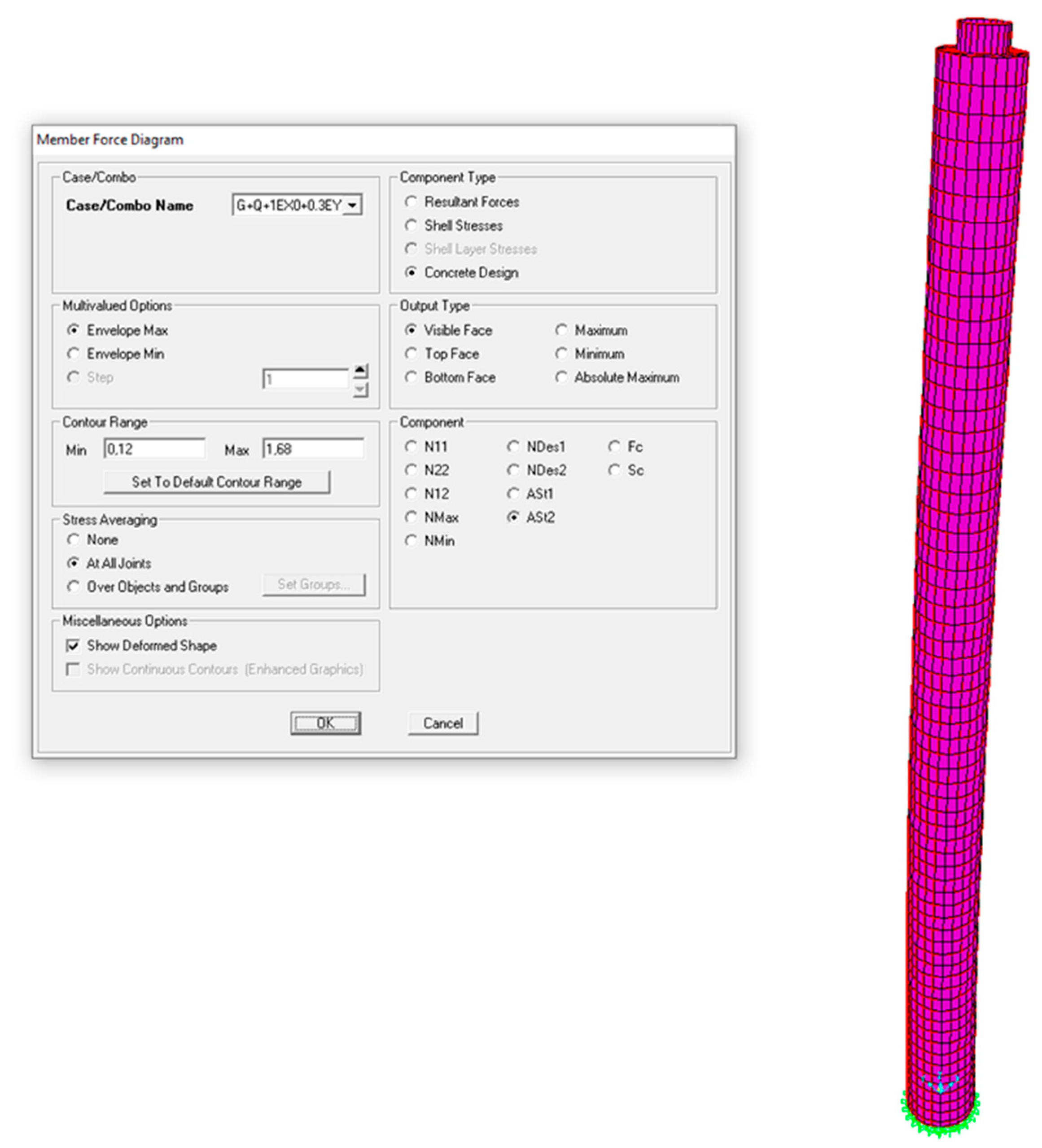
As shown in Figure 11, shell stresses due to vertical loads remain within safe limits, confirming structural adequacy. Figure 12 illustrates increased reinforcement in regions of higher demand, introduced to improve local strength and ensure ductile performance.
In the TBEC-2018 [2] analysis, 19 modes captured 100% of static mass and 91% of dynamic mass, indicating efficient modeling of the chimney's seismic behavior. In contrast, TBEC-2007 [3] required 24 modes to reach only 79%, showing that TBEC-2018 [2] more effectively concentrated the structural response in fewer dominant modes. This reflects a more accurate and sound dynamic assessment.
The comparative evaluation revealed significant differences in analysis methodology response coefficients, and modeling assumptions between TBEC-2018 [2] and TBEC-2007 [3]. The TBEC-2018 [2] framework resulted in a more critical assessment than TBEC-2007 [3], with higher calculated displacements, forces, and stresses.
This outcome is attributed to the improved dynamic analysis procedures and performance-based design parameters introduced in TBEC-2018 [2], including refined site classification methods, incorporation of vertical spectral accelerations, and updated material and detailing provisions. Specifically, TBEC-2018 [2] mandates the use of high-ductility reinforcement (e.g., B420C/B500C per TS 708 [32]), prescribes detailed rules for confinement, anchorage, lap splices, and limits on reinforcement ratios in critical regions. In contrast, TBEC-2007 [3] followed older TS 708 [33] standards, where reinforcement ductility classes were not clearly defined and seismic detailing requirements were comparatively limited. Moreover, TBEC-2007 [3] tends to underestimate structural demand due to its reliance on simpler load combinations, reduced safety factors, and less precise modeling strategies.
In conclusion, the TBEC-2018 [2] framework provides a more robust and accurate structural assessment than TBEC-2007 [3]. Its adoption of updated dynamic analysis methods, more conservative safety factors, and detailed modeling enhances reliability and supports the design of more resilient chimney structures.
4. Conclusions and Recommendations
This study investigated the seismic and wind performance of a 130-m R/C industrial chimney located at the Mersin Soda Factory, a facility of Şişecam A.Ş. The chimney, whose flue is insulated with firebrick and rock wool, is supported on an 18-m-diameter circular raft foundation with a thickness of 2 m. Structural analyses were conducted using the Modal Response Spectrum Method—a linear response spectrum method permitted in TBEC-2018 [2]—implemented in SAP2000 software [1]. The study aimed to compare the effects of TBEC-2007 [3] and TBEC-2018 [2] on the global response of this high-rise chimney, particularly focusing on force demands, displacement behavior, and reinforcement requirements.
The primary objective was to evaluate how the updated provisions in TBEC-2018 [2] influence seismic and wind design outcomes when compared to TBEC-2007 [3]. To this end, a comprehensive analysis was conducted on the chimney using consistent modeling parameters, allowing direct comparison of key response quantities between the two codes. The results revealed that TBEC-2018 [2] leads to significantly higher force demands due to changes in fundamental design parameters—most notably the use of ZE-class soil, a lower response modification factor (R = 2.5), and higher design wind speed (40 m/s). In contrast, TBEC-2007 [3] assumes a stiffer soil class (ZD), a higher R value (3.0), and a lower wind speed (30 m/s), resulting in reduced base shear and moment values.
Quantitatively, the base shear force due to wind loads increased by approximately 98% in the TBEC-2018 [2] analysis, while the corresponding maximum base moment increased by 82%. Under earthquake loading, the base moment and shear force were also higher in TBEC-2018 [2]—by 46% and 31%, respectively—despite no significant change in the total structural weight. Displacement results showed minimal difference between the two codes, with the maximum seismic displacement at the top node remaining approximately 34 cm in both cases. However, reinforcement requirements were notably higher in TBEC-2018 [2], particularly near the base, reflecting the more conservative and performance-based approach of the updated regulation. This is attributable to both the higher force demands and the stricter detailing requirements, such as the mandatory use of high-ductility reinforcement (B420C/B500C per TS 708 [32]), limitations on lap splices, and increased confinement detailing in critical regions.
The Modal Response Spectrum Method proved effective for this type of slender, tall chimney structure, as it accounts for the contribution of multiple vibration modes and captures the dynamic characteristics more accurately than static methods. The findings confirm that chimney-type structures, due to their slenderness, height, and dynamic sensitivity, should not be analyzed using the same assumptions applied to conventional buildings. Instead, they require specialized consideration under seismic and wind loading, particularly when evaluated under TBEC-2018 [2] provisions.
The results demonstrate that TBEC-2018 [2] provides a more safety-oriented framework compared to TBEC-2007 [3]. Key regulatory changes include point-based seismic ground motion parameters obtained from AFAD [31], redefinition of building importance and occupancy classes, elimination of soil group categorization in favor of detailed soil classes, and the introduction of vertical design spectra and building height classifications. These changes enable a more refined and site-specific structural design process.
It should be noted that this study used a linear analysis method common to both codes. While the results clearly highlight the increased demands under TBEC-2018 [2], they do not suggest the immediate need for structural retrofitting. More definitive conclusions on structural adequacy would require nonlinear analysis methods, which were beyond the scope of this study.
For future research, nonlinear static or dynamic analyses should be performed to more accurately assess the inelastic behavior and performance levels of such structures. Additionally, experimental or monitoring studies on similar industrial chimneys would further support the calibration of analytical models and improve the reliability of design under current seismic codes.
Author Contributions
Conceptualization, T.-S.Y.; methodology, T.-S.Y.; software, U.D.; validation, T.-S.Y. and U.D.; formal analysis, T.-S.Y.; investigation, U.D.; resources, T.-S.Y.; data curation, T.-S.Y.; writing—original draft preparation, T.-S.Y.; writing—review and editing, T.-S.Y.; visualization, T.-S.Y.; supervision, T.-S.Y.; project administration, T.-S.Y.; funding acquisition, not applicable. All authors have read and agreed to the published version of the manuscript.
Funding
This research received no external funding.
Data Availability Statement
The data presented in this study are available in the master’s thesis by Doğan, U. (2025), Design of industrial chimney-type structures according to the Turkish Building Earthquake Code, at the Council of Higher Education Thesis Center: https://tez.yok.gov.tr
Conflicts of Interest
The authors declare no potential conflict of interest with respect to the research, authorship, and/or publication of this article.
References
- Computers and Structures, Inc. SAP2000, Integrated Software for Structural Analysis and Design, Version 25.0.0; Computers and Structures, Inc.: Berkeley, CA, USA, 2023.
- AFAD. Turkey Building Earthquake Code; Disaster and Emergency Management Presidency: Ankara, Turkey, 2018.
- Ministry of Public Works and Settlement. Regulation on Buildings to Be Constructed in Earthquake Zones; Ministry of Public Works and Settlement, General Directorate of Disaster Affairs, Earthquake Research Department: Ankara, Turkey, 2007.
- Kareem, A.; Hseih, J. Reliability Analysis of Concrete Chimneys under Wind Loading. J. Wind Eng. Ind. Aerodyn. 1986, 25, 93–112. [Google Scholar] [CrossRef]
- Wilson, J.L. Earthquake Response of Tall Reinforced Concrete Chimney. Eng. Struct. 2003, 25, 11–24. [Google Scholar] [CrossRef]
- Huang, W.; Gould, P.L.; Martinez, R.; Johnson, G.S. Non-linear Analysis of a Collapsed Reinforced Concrete Chimney. Earthquake Eng. Struct. Dyn. 2004, 33, 485–498. [Google Scholar] [CrossRef]
- Chmielewski, T.; Górski, P.; Beirow, B.; Kretzschmar, J. Theoretical and Experimental Free Vibrations of Tall Industrial Chimney with Flexibility of Soil. Eng. Struct. 2005, 27, 25–34. [Google Scholar] [CrossRef]
- Huang, W.; Gould, P.L. 3-D Pushover Analysis of a Collapsed Reinforced Concrete Chimney. Finite Elem. Anal. Des. 2007, 43, 879–887. [Google Scholar] [CrossRef]
- Öz, E. Linear and Nonlinear Structural Analysis Methods of Reinforced Concrete Chimneys; Master’s Thesis, Karadeniz Technical University: Trabzon, Turkey, 2007.
- Şengün, İ. Computer Aided Design of Reinforced Concrete Industrial Chimneys; Master’s Thesis, Istanbul Technical University: Istanbul, Turkey, 2010.
- International Committee for Industrial Construction (CICIND). Model Code for Concrete Chimneys with Commentaries; International Committee for Industrial Construction: Moers, Germany, 2001.
- American Concrete Institute (ACI). Code Requirements for Reinforced Concrete Chimneys (ACI 307-08); ACI World Headquarters: Farmington Hills, MI, USA, 2008.
- British Standards Institution (BSI). Free-Standing Chimneys: General Requirements (BS EN 13084-1); British Standards Institution: London, England, 2007.
- Turkish Standards Institution (TSE). Calculation Values of Loads to Be Taken in Dimensioning of Building Elements (TS 498); Turkish Standards Institution: Ankara, Turkey, 1997.
- Elias, S.; Matsagar, V.; Datta, T.K. Effectiveness of Distributed Tuned Mass Dampers for Multi-Mode Control of Chimney under Earthquakes. Eng. Struct. 2016, 124, 1–16. [Google Scholar] [CrossRef]
- Akniyazov, D. Effectiveness of Diagonal Opening Reinforcement in Reinforced Concrete Chimneys under Gravity and Lateral Service Loads; Master’s Thesis, Boğaziçi University: Istanbul, Turkey, 2016.
- Kılıç, S.A. Modeling of Reinforced Concrete Chimney Section Behavior under Cyclic Loading Using Finite Element Method. J. Çukurova Univ. Fac. Eng. Archit. 2017, 32, 1–8. [Google Scholar]
- Türkeli, E. Effect of Soil-Structure Interaction on the Seismic Behavior of RC Chimneys. Düzce Univ. J. Sci. Technol. 2019, 7, 505–518. [Google Scholar] [CrossRef]
- Bashir, I. Comparative Study of an RC Chimney as per Different Codes; Master’s Thesis, Middle East Technical University: Ankara, Turkey, 2019.
- Küçük, M.M. Comparison of Design and Analysis of a Multi-Storey Reinforced Concrete Building According to the 2007 and 2018 Turkish Earthquake Codes; Master’s Thesis, Bursa, Turkey, 2020.
- Sarı, M. Effect of Structure-Soil Interaction on Dynamic Behavior of Reinforced Concrete Industrial Chimneys; Master’s Thesis, Recep Tayyip Erdoğan University: Rize, Turkey, 2020.
- ANSYS, Inc. ANSYS Analysis System: Engineering Simulation Software; ANSYS, Inc.: Canonsburg, PA, USA.
- Çaycı, B.T.; Eldemir, O. Comparison of Performance Levels of TBDY 2018 and DBYBHT 2007 Earthquake Codes. J. Eng. Sci. Des. 2021, 9, 1386–1397. [Google Scholar]
- Çiçek, A. Investigation of Earthquake Effects on Reinforced Concrete Industrial Chimneys and Calculation of These Structures According to Earthquake Loads; Master’s Thesis, Ondokuz Mayıs University: Samsun, Turkey, 2021.
- Alihassan, A. Analysis of GFRP Strengthened Industrial Reinforced Concrete Chimneys Using Finite Element Method; Master’s Thesis, Samsun University: Samsun, Turkey, 2021.
- Elhıdır, S. Analysis of Reinforced Concrete Chimneys under the Effect of Temperature Change by Using Finite Element Method; Master’s Thesis, Ondokuz Mayıs University: Samsun, Turkey, 2023.
- Turkish Standards Institution (TSE). Design and Construction Rules for Reinforced Concrete Structures (TS 500); Turkish Standards Institution: Ankara, Turkey, 2000.
- Şişecam A.Ş. Construction and Corrosion Control Unit, Mersin Soda Factory; Şişecam A.Ş.: Mersin, Turkey, 2024.
- European Commission (EC). Eurocode 1 - Actions on Structures - Part 1-4: General Actions - Wind Actions (EN 1991-1-4); DG Joint Research Center - Unit E3: Safety and Security of Buildings: Ispra (VA), Italy, 2005.
- Turkish Standards Institution (TSE). Effects on Buildings - Part 1-4: General Effects - Wind Effects (Eurocode 1); Turkish Standards Institution: Ankara, Turkey, 1997.
- AFAD. Official Earthquake Hazard Map of Turkey; Disaster and Emergency Management Presidency: Ankara, Turkey, 2018.
- Turkish Standards Institution. TS 708:2016, Steel for the Reinforcement of Concrete – Classes, Properties, and Tests; Turkish Standards Institution: Ankara, Turkey, 2016.
- Turkish Standards Institution. TS 708:2001, Steel for the Reinforcement of Concrete – Classes, Properties, and Tests; Turkish Standards Institution: Ankara, Turkey, 2001.
Figure 1.
General view of the Mersin Soda Factory chimney [28].
Figure 1.
General view of the Mersin Soda Factory chimney [28].
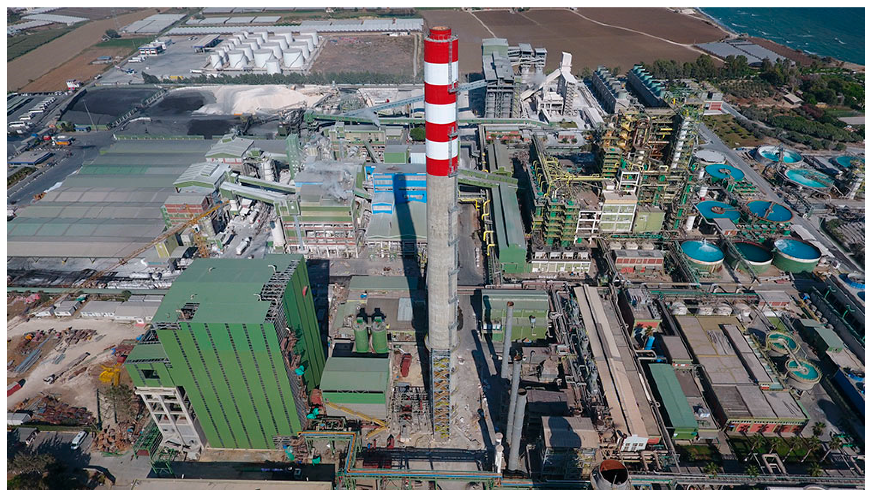
Figure 2.
External section view [28].
Figure 2.
External section view [28].
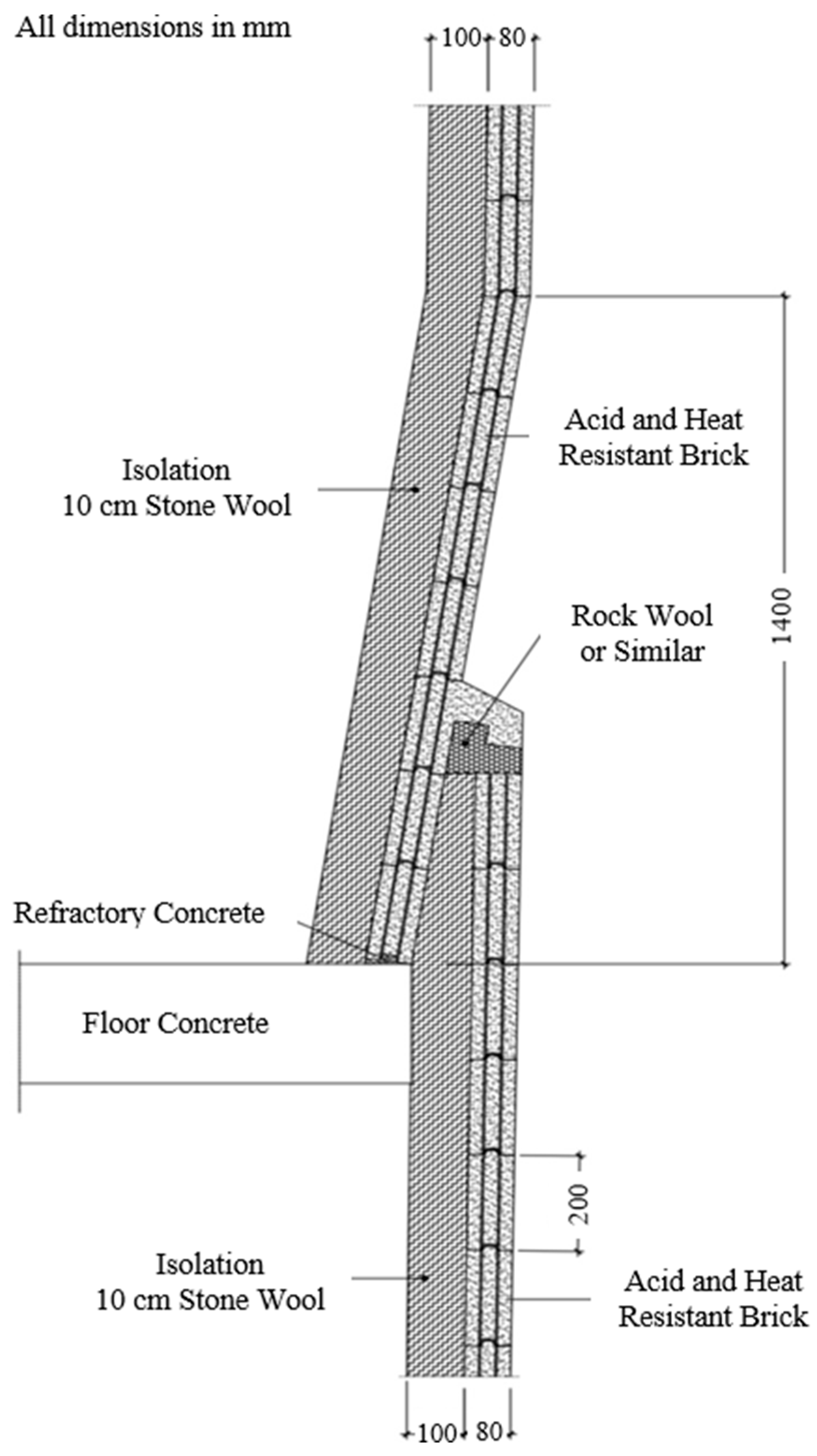
Figure 3.
Chimney longitudinal view [28].
Figure 3.
Chimney longitudinal view [28].
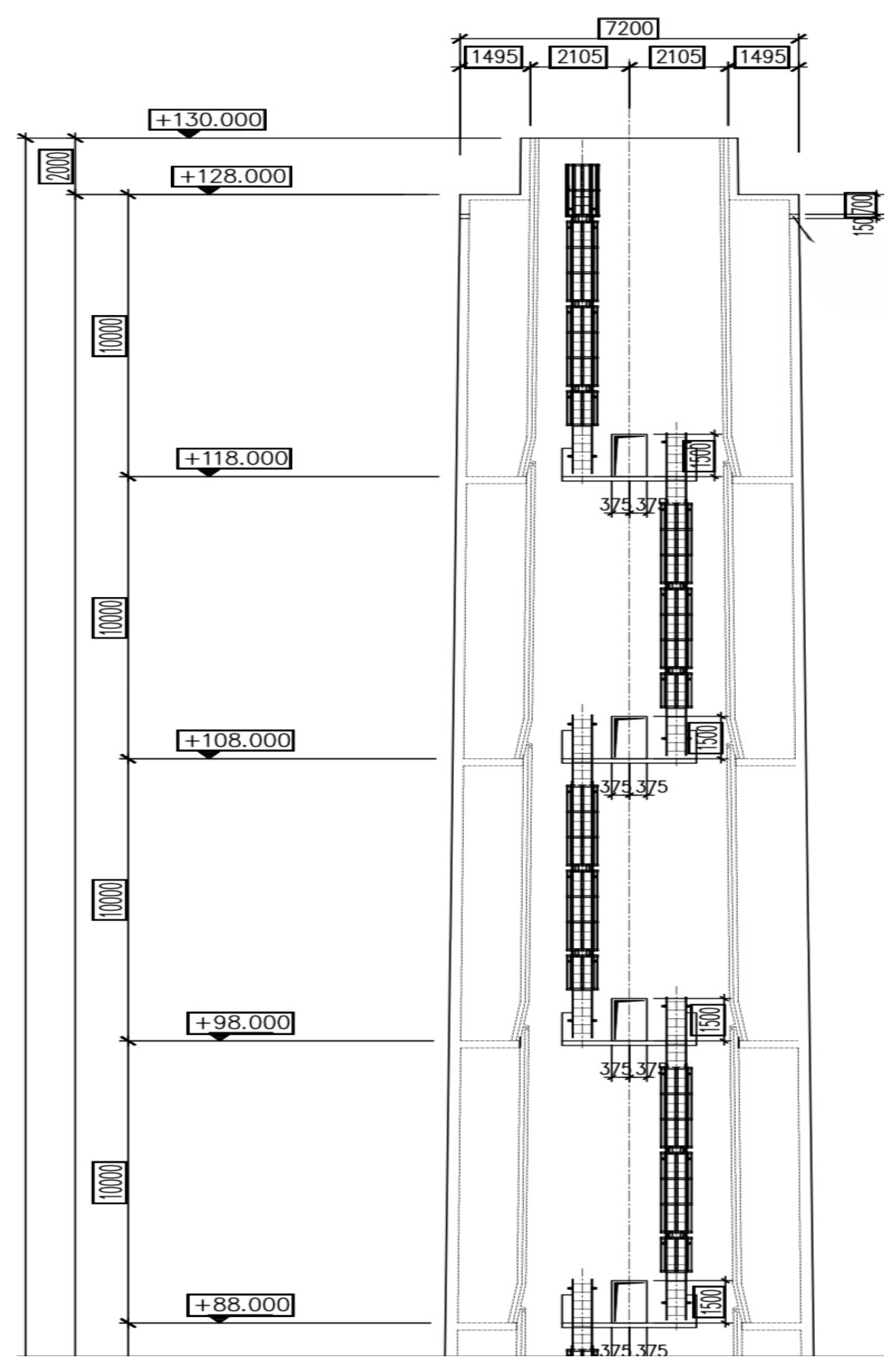
Figure 4.
Geometry of the thin shell element used in the analysis [16].
Figure 4.
Geometry of the thin shell element used in the analysis [16].
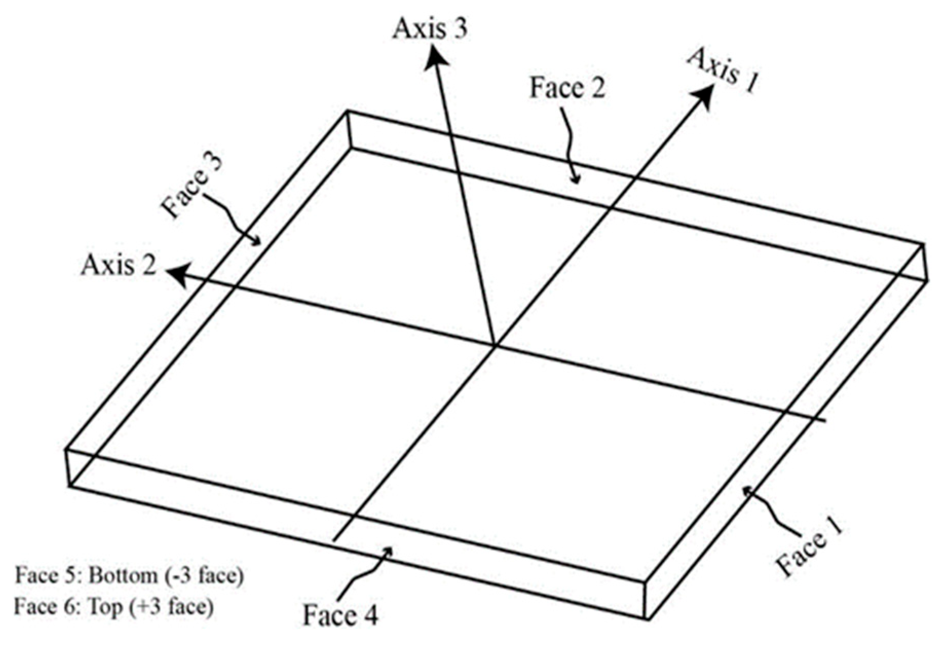
Figure 5.
Typical conceptual cross-section of the R/C chimney wall [16].
Figure 5.
Typical conceptual cross-section of the R/C chimney wall [16].
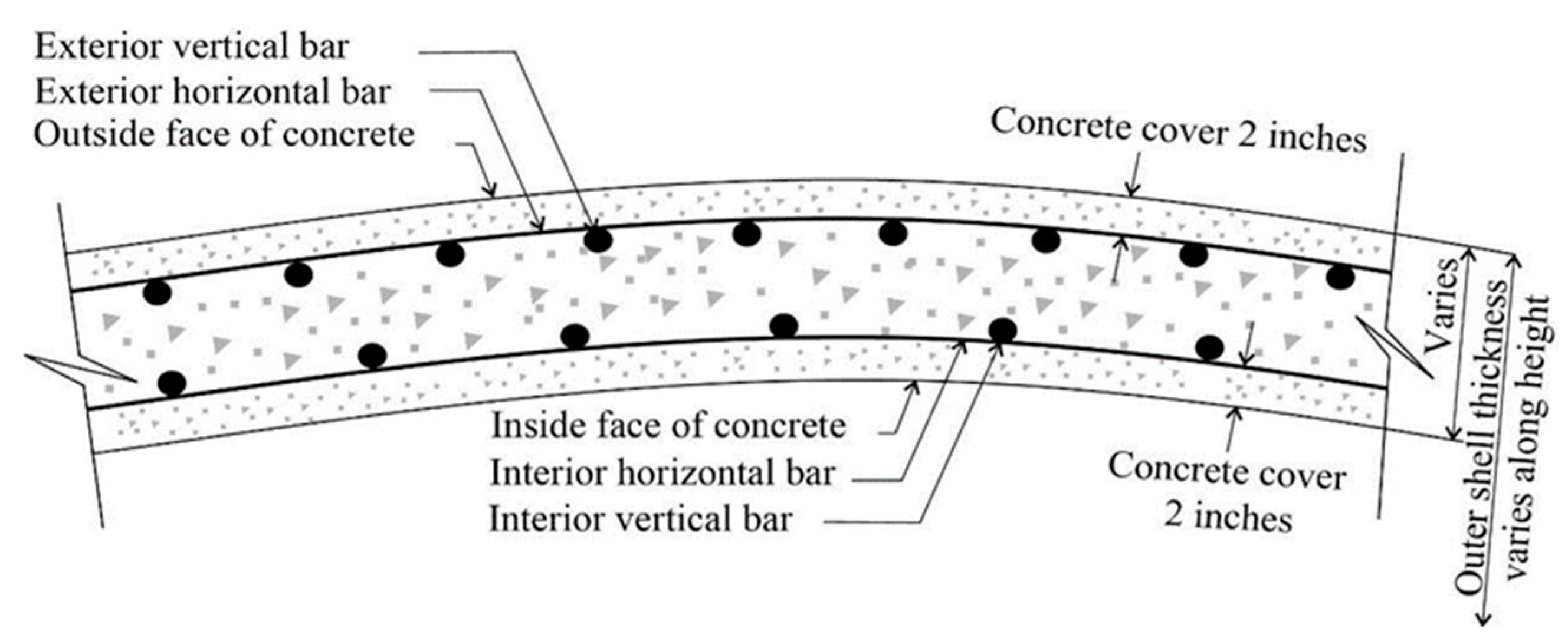
Figure 6.
Sectioned three-dimensional view of the chimney structure.
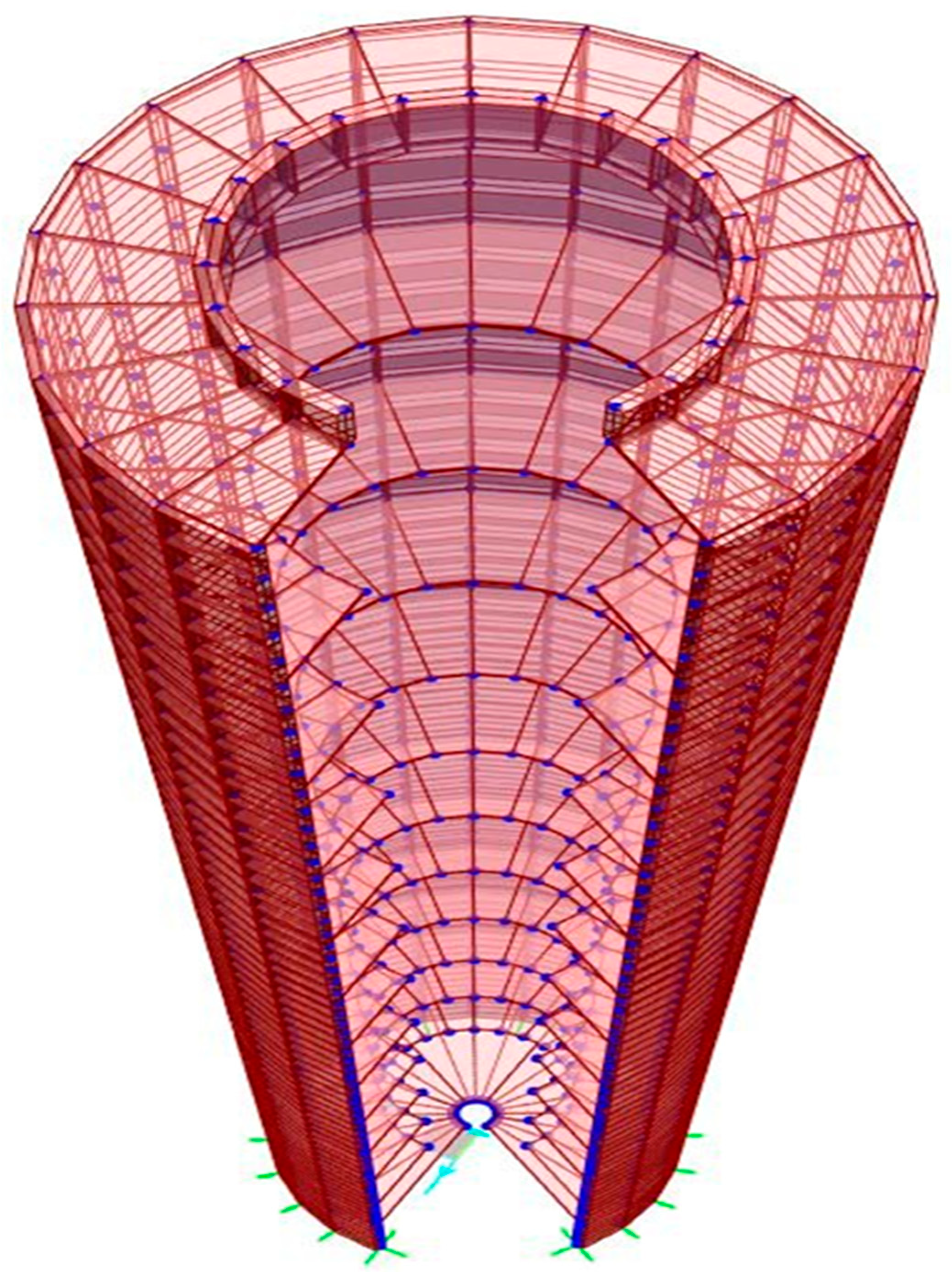
Figure 7.
Deformed shape of the chimney under wind load case, showing maximum displacement at the top.
Figure 7.
Deformed shape of the chimney under wind load case, showing maximum displacement at the top.
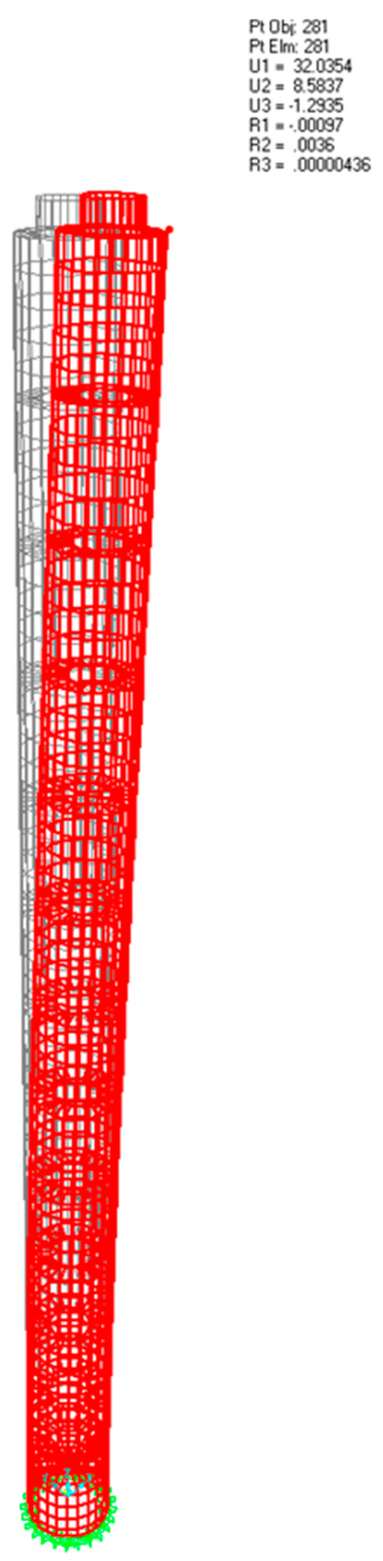
Figure 8.
Nodal configuration at chimney top region.
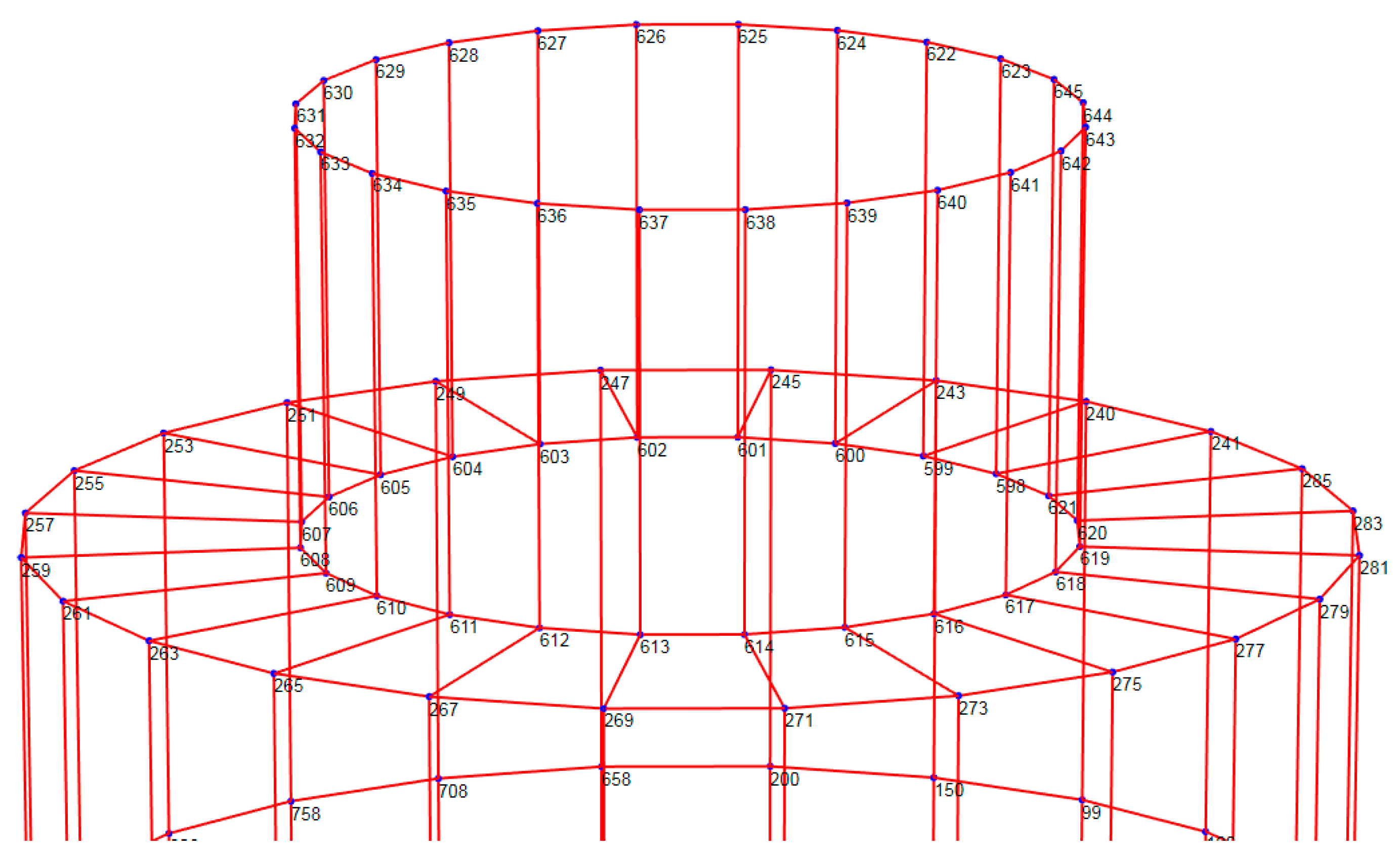
Figure 9.
Shell stress distribution due to wind load combination.
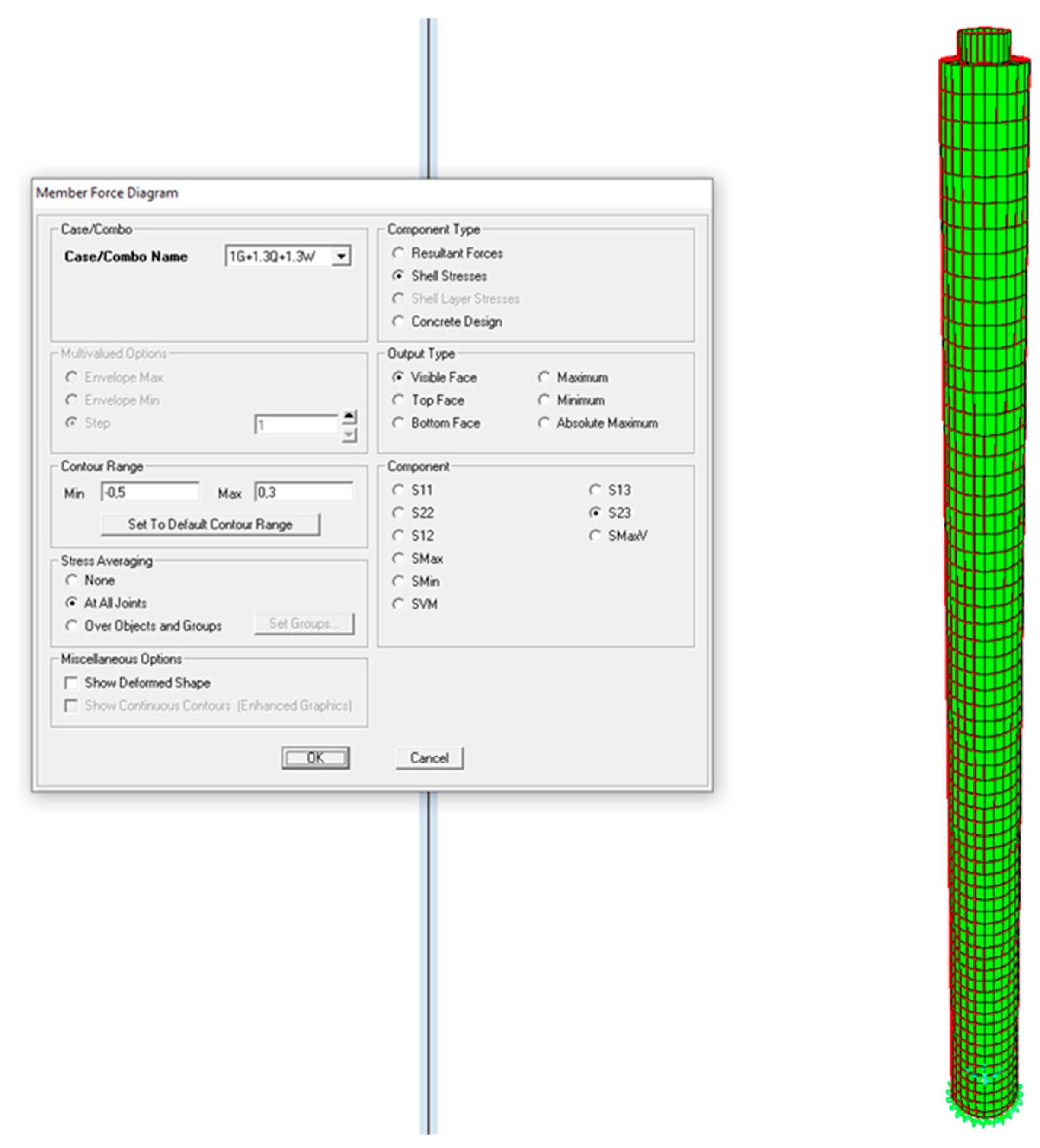
Figure 10.
Shell stress distribution due to earthquake load combination.
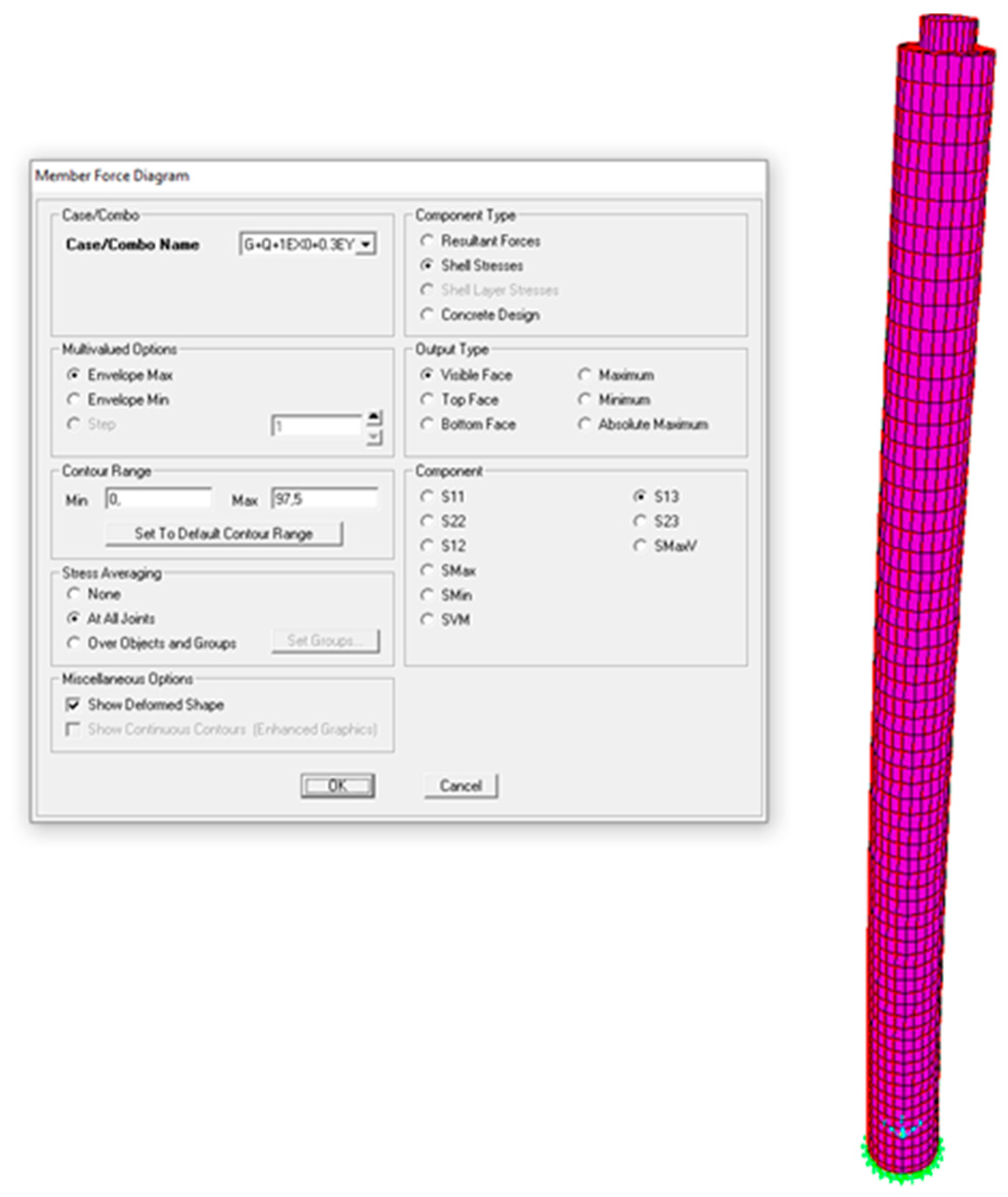
Figure 11.
Shell stress distribution under vertical (gravity) loads.
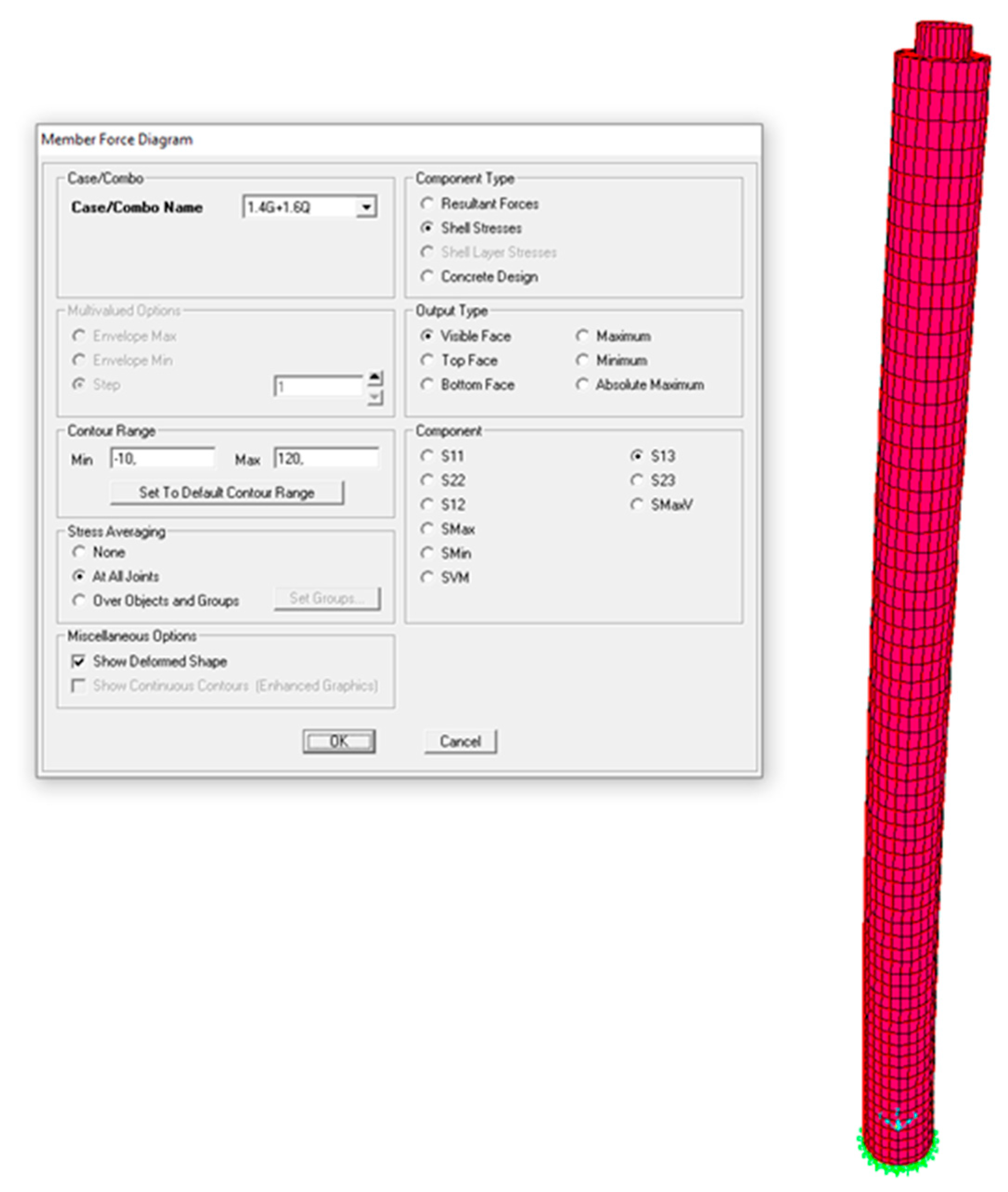
Figure 12.
Reinforcement detailing on chimney shell upper surface.

| Height above ground (m) | (kN/m2) | Diameter (m) | Reynolds number | Force coefficient | Wind force per m2 (kN) | Ref. area (m2) | Wind force per meter (kN/m) | Wind Pressure (kN/m2) | |
|---|---|---|---|---|---|---|---|---|---|
| 8 | 1.16 | 9.10 | 2.64E+06 | 0.49 | 1.25 | 0.71 | 72.8 | 51.5 | 0.71 |
| 18 | 2.33 | 8.91 | 3.66E+06 | 0.50 | 1.25 | 1.44 | 89.1 | 128.5 | 1.44 |
| 28 | 3.51 | 8.75 | 4.42E+06 | 0.50 | 1.25 | 2.20 | 87.5 | 192.9 | 2.20 |
| 38 | 3.74 | 8.60 | 4.48E+06 | 0.50 | 1.25 | 2.35 | 86 | 202.0 | 2.35 |
| 48 | 3.93 | 8.44 | 4.51E+06 | 0.51 | 1.25 | 2.51 | 84.4 | 211.5 | 2.51 |
| 58 | 4.1 | 8.29 | 4.52E+06 | 0.51 | 1.25 | 2.61 | 82.85 | 216.5 | 2.61 |
| 68 | 4.22 | 8.13 | 4.50E+06 | 0.51 | 1.25 | 2.69 | 81.3 | 218.7 | 2.69 |
| 78 | 4.33 | 7.98 | 4.47E+06 | 0.53 | 1.25 | 2.84 | 79.75 | 226.6 | 2.84 |
| 88 | 4.43 | 7.82 | 4.43E+06 | 0.53 | 1.25 | 2.91 | 78.2 | 227.3 | 2.91 |
| 98 | 4.52 | 7.66 | 4.39E+06 | 0.53 | 1.25 | 2.97 | 76.6 | 227.2 | 2.97 |
| 108 | 5.53 | 7.51 | 4.76E+06 | 0.56 | 1.25 | 3.89 | 75.1 | 292.0 | 3.89 |
| 118 | 5.62 | 7.35 | 4.69E+06 | 0.56 | 1.25 | 3.95 | 73.5 | 290.4 | 3.95 |
| 128 | 5.7 | 7.20 | 4.63E+06 | 0.56 | 1.25 | 4.01 | 72 | 288.6 | 4.01 |
| Parameter | TBEC-2018 [2] | TBEC-2007 [3] |
|---|---|---|
| Wind displacement | 32 cm | 41.5 cm |
| Seismic displacement | 34 cm | 34 cm |
| Base shear (wind) | 274 t | 138 t |
| Base shear (earthquake, dynamic) | 216 t | 147 t |
| Base moment (earthquake, dynamic) | 10,175 t.m | 7,754 t.m |
| Max shell stress (wind) | 0.247 N/mm2 | — |
| Max shell stress (earthquake) | 0.112 N/mm2 | — |
| Total structural weight | 3,190 t | 3,057 t |
| Modal mass participation (dynamic modes) | 91% in 19 modes | ≥79% in 24 modes |
Disclaimer/Publisher’s Note: The statements, opinions and data contained in all publications are solely those of the individual author(s) and contributor(s) and not of MDPI and/or the editor(s). MDPI and/or the editor(s) disclaim responsibility for any injury to people or property resulting from any ideas, methods, instructions or products referred to in the content. |
© 2025 by the authors. Licensee MDPI, Basel, Switzerland. This article is an open access article distributed under the terms and conditions of the Creative Commons Attribution (CC BY) license (http://creativecommons.org/licenses/by/4.0/).
Copyright: This open access article is published under a Creative Commons CC BY 4.0 license, which permit the free download, distribution, and reuse, provided that the author and preprint are cited in any reuse.


