Submitted:
10 September 2025
Posted:
12 September 2025
You are already at the latest version
Abstract
In this paper, the torque characteristics in dual three-phase (DTP) permanent magnet synchronous machines (PMSMs) with asymmetric interior permanent magnet (AIPM) rotors are investigated. The electromagnetic performances of DTP PMSMs with symmetrical and asymmetric IPM rotors are compared, including air-gap flux density, back EMF, cogging torque, torque, loss, and efficiency. It is found that in DTP PMSMs, the AIPM rotor can achieve significant torque improvement under both healthy and single three-phase open-circuit conditions. It is also found that performance enhancement in AIPM DTP machine is more remarkable across the constant-torque region particularly at high load conditions than in the constant-power region, compared with the symmetrical IPM counterpart. A prototype is fabricated and tested to verify theoretical analyses.
Keywords:
asymmetric interior permanent magnet rotor
; dual three-phase
; interior permanent magnet rotor
; permanent magnet synchronous machine
1. Introduction
In recent years, multi-phase permanent magnet synchronous machines (PMSMs) have been widely researched due to their advantages of high power/torque density, high efficiency, reduced current/power rating per phase, and enhanced fault-tolerance capability [1,2,3]. Compared with other types of multi-phase PMSMs, dual three-phase (DTP) PMSMs have attracted more attentions since commercial standard three-phase inverters can be employed directly and the control strategy is relatively easier in DTP PMSMs [4,5,6,7,8,9,10,11,12,13]. In addition, considering the independent two winding sets in DTP PMSMs, the faults in one three-phase winding set will not lead to the full loss of torque output and the fault-tolerant control strategy in DTP PMSMs is also easier than other multi-phase PMSMs [4,5].
Regardless of winding configuration, the rotors in DTP PMSMs can be generally classified into surface-mounted permanent magnet (SPM) rotors [6,7,8,9] and interior permanent magnet (IPM) rotors [10,11,12,13]. Compared with IPM rotors, the PMs in SPM rotors are placed closer to air-gap, and the flux leakages in SPM rotors are smaller. However, the d- and q-axis inductances are almost the same in SPM rotors. Thus, SPM rotors cannot produce reluctance torque. In IPM rotors, the existence of rotor saliency makes it possible to utilize both PM torque and reluctance torque at the same time [11,12]. What is more, the PMs in IPM rotors are buried in rotor cores, which means that there is no need to consider glass/carbon fiber-banding under high-speed. Thus, IPM rotors are especially suitable for variable-speed applications, such as electric vehicles [12,13].
To further improve the torque performances of PMSMs with IPM rotors, asymmetric IPM (AIPM) rotor topologies have been investigated in some papers [14,15,16,17,18,19,20,21,22,23,24,25,26,27]. In [14], the adoption of assisted flux barriers in V-type IPM machines displaces the axis of reluctance torques, which increases the average torque. In [15,16,17,18], the asymmetric magnet and flux barrier are optimized synchronously in PM assisted synchronous reluctance machines. The axes of the PM and reluctance torque components can also be shifted closer by combining different types of rotor topologies [19,20,21,22,23,24]. For example, the asymmetric inset SPM rotor structures introduced in [19,20] can be seen as compositions of SPM rotor and reluctance rotor. In addition, besides in circumferential direction [19,20], SPM rotor and reluctance rotor can also be composed together in axial direction [21,22]. Further, besides the combination of SPM and reluctance rotors, asymmetric rotors can also be combined by SPM and IPM rotors [23] or by different types of IPM rotors (e.g., I-type and spoke-type PMs in [24], V-type and spoke-type PMs in [25]). All these asymmetric rotor designs can shift the reluctance torque axis closer to PM torque axis in PMSMs, and thus, utilization ratios of PM and reluctance torque components can be improved simultaneously [26,27].
However, all existing papers only focus on conventional single three-phase (STP) winding configuration, the effects of AIPM rotors on the electromagnetic characteristics in DTP PMSMs have not been analyzed. Therefore, this paper aims to fill this gap by investigating and comparing the influences of symmetrical and asymmetric IPM rotors on electromagnetic performances in DTP PMSMs. Both healthy and single three-phase open-circuit (OC) conditions are considered.
This paper is organized as follows. In Section II, the topologies and working principles of the analyzed DTP PMSMs with IPM and AIPM rotors are described. The electromagnetic performances of the DTP PMSMs with IPM and AIPM rotors are compared under healthy condition in Section III, and under single three-phase OC in Section IV. In Section V, a prototype of DTP PMSM with AIPM rotor is manufactured and tested to verify the analyses. Finally, conclusions are drawn in Section VI.
2. Machine Configuration and Operation Principle
In this paper, the effects of AIPM rotors in DTP PMSMs are investigated based on Toyota Prius 2010 machine and the results are compared with those obtained with the original symmetrical IPM rotor. Considering that the original Toyota Prius 2010 machine is equipped with STP windings, the DTP winding configuration for Toyota Prius 2010 machine will also be introduced in this section.
2.1. Machine Configuration
In Toyota Prius 2010 machine, the slot/pole number combination is 48-slot/8-pole, and the original armature windings are single-layer short-pitched STP windings [28]. Compared with STP winding configuration, DTP winding configuration with 30° phase shift can improve average torque and reduce torque ripples inherently. Hence, to enhance the torque performance of the original Toyota Prius 2010 machine, two DTP winding configurations are proposed and compared in [29]. In this paper, the single-layer full-pitched DTP winding configuration is selected for further analyses due to their advantages of enhanced average torque capability and easier manufacture. The winding arrangement and the coil electromotive force (EMF) phasor diagram of the single-layer full-pitched DTP windings are shown in Figure 1(a) and (b), respectively. The phase shift angle (30°) can be observed clearly from Figure 1(b).
The AIPM rotor design analyzed in this paper is firstly proposed in [30], based on Toyota Prius 2010 machine for STP stator windings, which features with skewed V-type PMs and a flux barrier outside PMs. The cross-sections of the benchmark DTP PMSMs with the original symmetrical IPM rotor (designated as IPM rotor in the rest of the paper) and the AIPM rotor are illustrated in Figure 2(a) and (b), respectively. The detailed geometric dimensions of Toyota Prius 2010 machine, including the stator and the IPM rotor and the AIPM rotor can be found from [28,30], respectively, and some key geometric parameters are listed in Table 1.
2.1. Operation Principle
Although the winding configurations in DTP PMSMs are different from those in STP counterparts, the output torques of DTP and STP PMSMs are both composed by PM and reluctance torque components. Thus, the operation principle of AIPM rotors in DTP PMSMs is identical to that in STP PMSMs. PM torque component is produced by the interaction between armature windings and PM magnetic field, while reluctance torque is produced due to the rotor saliency. Compared with IPM rotor, AIPM rotor shifts the axis of PM magnetic field and changes the location of rotor saliency simultaneously. Thus, when using AIPM rotor in PMSMs, the optimal current advancing angles for maximum PM and reluctance torque components are no longer the same as those obtained using IPM rotor. With appropriate AIPM rotor designs, the optimal current advancing angles for maximum PM and reluctance torque components can be much closer to each other. Thus, both PM and reluctance torque components can be utilized more effectively with the same current advancing angle. To further illustrate the difference between the torque components in PMSMs with IPM and AIPM rotors, the torque components versus current advancing angle characteristics in the PMSMs with different rotors are plotted in Figure 3. Overall, compared with the IPM counterpart, the magnetic field shifting (MFS) effect caused by AIPM rotor makes it possible to produce higher average torque. In the analyzed AIPM rotor, as shown in Figure 2(b), the different sizes of two interior PMs and the extra flux barrier can make the MFS effect even more evident.
3. Comparison of Electromagnetic Performance of DTP PMSMs with IPM and AIPM Rotors Under Healthy Condition
In this section, the electromagnetic performances of the benchmark DTP PMSMs with IPM and AIPM rotors are compared, including air-gap flux density, back EMF, cogging torque, torque, loss, and efficiency. It should be mentioned that all the analyses presented below are based on the results obtained from JMAG-Designer by using 2-dimensional (2D) finite element (FE) method.
3.1. Open-Circuit Characteristics
The flux line distributions of the DTP PMSMs with IPM and AIPM rotors under OC are firstly calculated and compared, as shown in Figure 4. As can be seen, due to the middle-side small magnet and the outside flux barrier in one AIPM rotor pole, closed flux lines can be observed. The waveforms and spectra of the radial flux densities along air-gaps air-gap under this condition are shown in Figure 5 (a) and (b). In Figure 5 (a), the fluctuations can be explained by the asymmetric rotor layout and the closed flux lines in one AIPM rotor pole. From Figure 5 (b), it can be clearly seen that the AIPM rotor has higher fundamental component, which can be attribute to the flux-focusing effect caused by the flux barrier in the AIPM rotor. However, the AIPM machine also shows more harmonic contents compared with the IPM counterpart, which may result in larger eddy current loss in the AIPM machine. Hence, the flux density distributions of the benchmark PMSMs under OC suggest that the loss and efficiency of the DTP PMSMs with IPM and AIPM rotors need more attention in the following analyses.
In the DTP PMSMs with IPM and AIPM rotors, assuming rotor speed is 200 rpm, the waveforms and spectra of phase back electromotive forces (EMFs) of Phases A1 and A2 are shown in Figure 6. From Figure 6(b), it can be seen that similar to the OC air-gap flux density, the amplitude of the fundamental back EMF in the AIPM machine is higher than that in the IPM machine.
For the DTP PMSMs with IPM and AIPM rotors, the waveforms and spectra of the cogging torques are given in Figure 7 (a) and (b). Due to the same slot/pole number combination, the fundamental orders of cogging torque in IPM and AIPM machines are exactly the same, which is 48 in mechanical angle (the smallest common multiple between slot number, 48, and pole number, 8) and 12 in electric angle, but the amplitudes of the same harmonic order are different in IPM and AIPM machines. In the analyzed DTP PMSMs, the cogging torque produced by the AIPM rotor is much larger than that produced by the IPM rotor.
3.2. Torque Characteristics
In this part, the torque characteristics of the DTP PMSMs with IPM and AIPM rotors are compared under full load firstly. In the Toyota Prius 2010 machine, the phase current amplitude under full load is 236 A, and in the benchmark DTP PMSMs, due to different winding configurations, the phase current amplitude for the full load is 118 A. In the DTP PMSMs with IPM and AIPM rotors, the variations of average torque with current advancing angle under full load (IA1 = 118Apk) are shown in Figure 8. It can be seen that the maximum average torques are obtained when current advancing angle = 53° in IPM machine, and 62° in AIPM machine.
As mentioned before, in IPM and AIPM machines, the variations of PM and reluctance torque components with current advancing angle are quite different. With the help of frozen permeability method [32,33,34], the PM and reluctance torque components can be separated from the total average torque. The variations of PM and reluctance torque components with current advancing angle are also presented in Figure 8. It can be found that the optimal current advancing angles for the maximum PM torque component are 24° in IPM machine, and 53° in AIPM machine. To achieve the maximum reluctance torque component, the optimal current advancing angles are 58° and 65° respectively in IPM and AIPM machines. The optimal current advancing angles for different torque components are summarized in Table 2. In the IPM machine, the difference between the optimal current advancing angles for the maximum PM and reluctance torque components is 34°, but in AIPM machine, the difference is only 12°. It can be concluded that compared with IPM rotor, the PM and reluctance torque components in the DTP PMSMs can be better utilized by using AIPM rotor.
From Figure 8 and Table 2, under full load (IA1 = 118 Apk), to achieve the maximum average torque, the optimal current advancing angles are 53° and 62° respectively in IPM and AIPM machines. With the optimal current advancing angles, the waveforms and spectra of the instantaneous torque in the DTP PMSMs with IPM and AIPM rotors are shown in Figure 9. The average torque and torque ripple characteristics of the PMSMs under full load are summarized in Table 3. It can be seen that compared with the DTP IPM machine, the DTP AIPM machine can increase the average torque by 9.25% and reduce the torque ripple by 47.62% under full load.
The prototype DTP PMSMs in this paper is modified from the STP PMSMs in [30] by changing winding configurations and optimize rotor design. With the STP windings, the torque characteristics of the STP PMSMs under full load are provided in Table 4. The results for DTP and STP PMSMs can be compared. Under full load, the STP AIPM machine can increase the average torque by 8.35% and reduce the torque ripple by 34.08% compared with the STP IPM machine. Hence, by employing AIPM rotor, DTP PMSM can achieve better improvement in average torque and more reduction in torque ripple than those in STP PMSM.
Under other load conditions, the optimal current advancing angles can also be obtained based on maximum torque per amplitude (MTPA) control strategy. In the DTP IPM and AIPM machines, assuming IA1 varies from 25 Apk to 250 Apk to cover the load conditions from light-load to over-load, the variations of average torques and torque ripples with phase current amplitude are shown in Figure 10(a) and (b), respectively. It can be seen that the average torque of the DTP PMSM can always be improved significantly by using the AIPM rotor and the average torque improvements are presented in Figure 10(c). In addition, when the phase current ≥ 75 Apk, not only the average torque can be improved, the torque ripple can also be reduced by the AIPM rotor. Hence, the AIPM rotor can greatly improve the torque performance of the DTP PMSM.
3.3. Loss and Efficiency
In this paper, the losses and efficiencies of the DTP PMSMs with IPM and AIPM rotors are obtained by using the method in [36,42]. The copper loss is calculated by using Joule’s law, as
where R0 is the phase resistance of the DTP windings, and Ia is the phase current amplitude.
In the calculation of iron losses, it consists of hysteresis and eddy current iron losses, which are calculated by:
where PHyst-base and PEddy-base are the hysteresis and eddy current iron losses at the base speed, i.e., 3000 rpm in this study. f and fbase are the frequencies of the operating condition and the base speed.
For other losses, PM eddy current losses are obtained from FE simulations directly, and mechanical losses are estimated by [43]
Overall, the loss characteristics of the DTP PMSMs with IPM and AIPM rotors under the full-load (IA1 = 118 Apk, speed = 3000 rpm) are summarized and compared in Table 5.
It can be seen that copper loss is the most dominant loss in both IPM and AIPM machines. Since the IPM and AIPM machines share the same stator and armature windings, the copper losses of the two DTP PMSMs are identical. Due to similar iron loss and higher PM eddy current loss, the total loss in AIPM machine is slightly higher than that in IPM counterpart. However, considering that the output torque and output power of the AIPM machine is obviously larger than those of the IPM counterpart, and the AIPM machine still has higher overall efficiency than the IPM counterpart under this condition.
To analyze the loss and efficiency characteristics of the DTP PMSMs with IPM and AIPM rotors at other speeds, the torque and power-speed curves of the two DTP PMSMs are calculated under the constraints (DC link voltage ≤ 650Vdc and phase current ≤ 118Apk), as shown in Figure 11. Similarly, the variations of the maximum d- and q-axis currents (Id and Iq), and phase currents (Ia) with speed are shown in Figure 12. It can be clearly seen that the AIPM machine can produce higher torque than the IPM counterpart not only in constant torque region (low-speed), but also in constant power region (high-speed).
Based on (1), (2), Figure 11, and Figure 12, the copper loss and iron loss maps of the DTP PMSMs with IPM and AIPM rotors are calculated, as shown in Figure 13 and Figure 14, respectively. The mechanical losses of the DTP IPM and AIPM machines are calculated by using (3), as shown in Figure 15.
Considering that PM eddy current loss under other speeds cannot be estimated directly from the base speed and the PM eddy current loss is very small in total loss, as indicated in Table 5, the ignorance of PM eddy current loss in the calculation of resultant efficiency is still acceptable. Thus, when ignoring PM eddy current loss, the total loss maps of the DTP IPM and AIPM machines can be obtained from Figure 13, Figure 14, and Figure 15, as shown in Figure 16. The total loss difference between AIPM and IPM machines is given in Figure 16(c). In Figure 16(c), the operating conditions can be classified into three conditions, i.e., low speed and low torque, low speed and high torque, and high-speed conditions. It can be observed that at high speed, iron loss is the dominant loss and the AIPM machine has higher total loss, while at low speed and high torque, copper loss is the dominant loss and the IPM machine has higher total loss. At low speed and low torque, the AIPM and IPM machines show similar total losses.
In Figure 14, it can be observed that the iron loss in the AIPM machine is higher than that in the IPM counterpart at high speed and low speed and low torque. However, in Table 5, it is shown that the iron loss of the AIPM machine is slightly lower than that of the IPM counterpart at full load (low speed and high torque). Considering that the phase currents under different operating conditions are different, it is necessary to further analyze the effects of electric loadings on iron losses in the DTP AIPM and IPM machines.
Assuming the phase currents varying from 0 to 250 Apk, the iron losses of the DTP PMSMs with IPM and AIPM rotors at 3000 rpm are compared in Figure 17. It can be observed that the iron loss in the DTP AIPM machine is higher than that in the IPM counterpart at low currents (≤ 50 Apk), but lower than that in the IPM counterpart at high loads (≥ 75 Apk). This phenomenon can be explained by the different air-gap MMF harmonic contents in the AIPM and IPM machines. When electric loading is low, the air-gap MMF is mainly produced by rotor PMs. Under open-circuit, the air-gap flux densities of the DTP AIPM and IPM machines are shown in Figure 5. From Figure 5(b), it can be obtained that the AIPM machine has higher fundamental component (0.77 T in IPM machine, and 0.92 T in AIPM machine) and more abundant harmonic contents (THD = 42.66% in IPM machine, 68.42% in AIPM machine). Hence, the iron loss of the DTP AIPM machine is significantly higher than that in the DTP IPM machine under low-load. However, with the increase of phase currents, the air-gap flux densities of the DTP AIPM and IPM machines are mainly affected by armature windings, and less affected by rotor PMs. Under full-load (IA1 = 118Apk), the air-gap flux densities of the DTP AIPM and IPM machines are compared in Figure 18.
It can be seen that the air-gap flux densities of the DTP IPM and AIPM machines are close to each other under this condition. In addition, due to different rotor layouts, the harmonic contents in the AIPM machine are even lower than those in the IPM counterpart under this condition (THD = 41.57% in IPM machine, 38.44% in AIPM machine). As a result, compared with DTP IPM machine, the DTP AIPM machine shows higher iron loss when electric loading is low (under low speed and low torque, and high-speed conditions) and lower iron loss when electric loading is high (at low speed and high torque).
Based on Figure 16, the efficiency maps of the DTP PMSMs with IPM and AIPM rotors are calculated, as shown in Figure 19(a) and (b), respectively. The efficiency difference between the AIPM and IPM machines is presented Figure 19(c).
It can be found that the DTP AIPM and IPM machines show higher efficiencies under different operating conditions. Due to the more abundant PM MMF harmonics in the DTP AIPM machine, DTP AIPM machine shows higher iron loss and lower efficiency than IPM counterpart at high-speed. However, when electric loading is higher, the iron losses due to armature reaction field become more significant and hence the iron losses in IPM and AIPM machines become similar to each other. Thus, the investigated DTP AIPM topology exhibit higher efficiency than the IPM counterpart at high torque and high load conditions due to the optimization goal only focusing on higher torque density [36].
4. Torque Characteristics Under Three-Phase OC Condition
Authors should discuss the results and how they can be interpreted from the perspective of previous studies and of the working hypotheses. The findings and their implications should be discussed in the broadest context possible. Future research directions may also be highlighted.
Since the two three-phase winding sets in DTP PMSMs are connected independently, any fault in one three-phase winding set will not result in the failure of total torque output and DTP PMSMs can still operate with only one three-phase winding set. The torque characteristics of the DTP PMSMs with IPM and AIPM rotors under single three-phase OCs are compared.
As mentioned before, in the analysed IPM and AIPM machines, the phase current amplitude is 118 A under healthy full load. When the phase current amplitude is 118A under single three-phase OC (IA1 = 118 Apk, IA2 = 0), the variations of total torque, PM torque, and reluctance torque with current advancing angle are shown in Figure 20, and the optimal current advancing angles under this condition are summarized in Table 5. The difference between the optimal current advancing angles for the maximum PM and the reluctance torque components is 25° for the IPM machine and it is 19° in the AIPM machine. Hence, under single three-phase OC, the MFS effect still can be observed, and thus, the AIPM rotor can still improve average torque.
From Table 6, under single three-phase OC, when IA1 = 118 Apk, the maximum average torques in the IPM and AIPM machines are obtained with current advancing angle = 38° and 49°, respectively. The waveforms and spectra of the instantaneous torque in the DTP PMSMs with IPM and AIPM rotors under this condition are shown in Figure 21 and the torque characteristics are summarized in Table 7. It can be seen that the average torque can still be improved significantly by the AIPM rotor, but the torque ripple is increased slightly by the AIPM rotor.
Similar to the analyses under healthy condition, when one three-phase winding set is open-circuited and IA1 varies from 25 Apk to 250 Apk, the variations of average torques and torque ripples with phase current amplitude are shown in Figure 22(a) and (b), respectively. It can be seen that the average torque can still be improved by the AIPM rotor, and the torque improvements are summarized in Figure 22(c). However, the torque ripple can only be reduced when the phase current ≥ 150 Apk. Overall, the AIPM rotor can still achieve significant torque improvement in the DTP PMSM under the single three-phase OC.
5. Experimental Verification
Considering the difficulties in manufacturing and testing a large prototype, which shares the same size as the Toyota Prius 2010 machine, small-scale 24-slot/4-pole prototypes are fabricated and tested to verify the FE analyses presented in this paper. The prototype DTP PMSMs are modified from the STP PMSMs in [36] by changing winding configurations.
Some key design specifications of the prototype are given in Table 8. The pictures of the DTP AIPM prototype are given in Figure 23, and the test rig is shown in Figure 24.
The FE predicted and measured waveforms and spectra of phase back EMF and cogging torque are compared in Figure 25 and Figure 26. The cogging toque is measured by using the method proposed in [37]. For the prototype machine, the phase back EMFs exhibit significant harmonics due to the asymmetric rotor layout. In Figure 25 (a), an asymmetric in the half waveform can be observed due to the small magnet between the large magnet and the flux barrier. It can also be found from Figure 25(b) that the measured fundamental and harmonic amplitudes are lower than the FE predicted results, which could be due to the neglect of end effects in 2D FE calculations. Although the AIPM rotor is not symmetrical from the view of one rotor pole, the whole rotor is still symmetrical as the four rotor poles share the same cyclic layout, and thus, there is no even harmonic in resultant phase back EMFs.
Due to the same slot/pole ratio, the fundamental order of cogging torque is 12 in electric for the 24-slot/4-pole prototype, which is identical to that in the 48-slot/8-pole PMSMs. The measured cogging torque validates the order number of the FE predicted results, but the measured cogging torque amplitude is much smaller than simulations.
To validate the FE analyses under on-load conditions, the two three-phase winding sets of the prototype are supplied by direct currents, and the static torque versus rotor position waveforms are measured under different current values. It should be noticed that due to the 30° phase shift between the two winding sets, the phase currents in the two winding sets are different at the same time, as shown in Figure 27. The direct currents in different phases are assigned as IA1=Idc, IB1=IC1=−0.5Idc, IA2=0.866Idc, IB2=0, and IC2=−0866Idc. To achieve the aforementioned currents, two DC supplies are utilized. The first winding set is supplied by a DC supply with Idc. Phases B1 and C1 windings are connected in parallel firstly and then connected with Phase A1 winding in series. The second winding set is supplied by another DC supply with 0.866Idc, which is supplied to series connected Phases A2 and C2 windings. Phase B2 winding is not supplied with current.
The FE predicted and measured waveforms, as well as their spectra of static torque versus rotor position characteristics of the prototype machine with different Idc values are compared in Figure 28. The corresponding variations of the fundamental amplitudes of static torque with Idc are compared in Figure 29. It can be seen that the measured results are lower than the FE predicted results, due to the neglecting of end-winding effects in 2D FE calculations. Overall, the good agreement between the FE predicted and tested results under OC and on-load conditions validate the accuracy of the FE analyses and conclusions drawn in this paper.
6. Conclusions
In this paper, the effects of an AIPM rotor topology on the electromagnetic performance of DTP PMSMs are investigated based on the Toyota Prius 2010 machine configuration. The electromagnetic performances of the DTP PMSM with AIPM rotor are compared with those obtained with IPM rotor. Both healthy and single three-phase OC conditions are considered. It is found that the MFS effect also exists in DTP PMSMs both under healthy and single three-phase OC conditions, and thus, the average torque can be improved significantly by using AIPM rotor. Furthermore, it is found that in DTP PMSMs, the average torque improvement by AIPM rotor is higher than that in STP PMSMs.
Overall, the benefits of AIPM rotors in STP PMSMs, such as higher average torque and lower torque ripple, still exist in DTP PMSMs and the torque improvement can still be achieved even under single three-phase OC in DTP PMSMs.
In addition, it is also found that due to the more abundant PM MMF harmonics, the DTP AIPM machine shows higher iron loss and lower efficiency than symmetrical IPM counterpart when the torque load is low, particularly in the high-speed region, albeit to the torque enhancement across all regions. However, when electric loading is higher, the iron losses due to armature reaction field become more significant and hence the difference between the iron losses in IPM and AIPM machines becomes smaller. As traction machines in EVs have variable operation conditions, the AIPM rotor design for DTP machines in EV applications should be comprehensively optimized considering wide operation ranges, rather than only focusing on high torque density at singular operation point.
Author Contributions
Conceptualization, Z.Q.Z. and S.W.; methodology, S.W. and Z.Q.Z.; software, S.W.; validation, S.W., Y.X., and Z.Q.Z.; formal analysis, S.W. and Z.Q.Z.; investigation, S.W. and Z.Q.Z.; resources, Z.Q.Z.; data curation, S.W.; writing—original draft preparation, S.W.; writing—review and editing, Z.Q.Z., Y.X., and D.L.; visualization, S.W.; supervision, Z.Q.Z.; project administration, Z.Q.Z.; funding acquisition, Z.Q.Z. All authors have read and agreed to the published version of the manuscript.
Conflicts of Interest
The authors declare no conflicts of interest.
References
- N. Gadiyar, J. Van de Ven and E. L. Severson, “Evaluation of torque-dense electric machine technology for off-highway vehicle electrification,” IEEE Transactions on Industry Applications, vol. 60, no. 2, pp. 3062-3074, March-April 2024. [CrossRef]
- E. Levi, “Multiphase electric machines for variable-speed applications,” IEEE Trans. Ind. Electron., vol. 55, no. 5, pp. 1893–1909, May 2008. [CrossRef]
- W. P. Cao, B. C. Mecrow, G. J. Atkinson, J. W. Bennett, and D. J. Atkinson, “Overview of electric motor technologies used for more electric aircraft (MEA),” IEEE Trans. Ind. Electron., vol. 59, no. 9, pp. 3523-3531, Sep. 2012. [CrossRef]
- M. Barcaro, N. Bianchi, and F. Magnussen, “Six-phase supply feasibility using a PM fractional-slot dual winding machine,” IEEE Trans. Ind. Appl., vol. 47, no. 5, pp. 2042–2050, Sep./Oct. 2011.
- M. Barcaro, N. Bianchi, and F. Magnussen, “Faulty operations of a PM fractional-slot machine with a dual three-phase winding,” IEEE Trans. Ind. Electron., vol. 58, no. 9, pp. 3825–3832, Sep. 2011. [CrossRef]
- A. S. Abdel-Khalik, S. Ahmed, and A. Masmoud, “Low space harmonics cancellation in double layer fractional slot winding using dual multi-phase winding,” IEEE Trans. Magn., vol. 51, no. 5, May 2015, Art. no. 8104710. [CrossRef]
- A. Abdel-Khalik, S. Ahmed, and A. Massoud, “A six-phase 24 slot-10 pole permanent-magnet machine with low space harmonics for electric vehicle applications,” IEEE Trans. Magn., vol. 52, no. 6, Jun. 2016, Art. no. 8700110. [CrossRef]
- Y. Demir and M. Aydin, “A novel dual three-phase permanent magnet synchronous motor with asymmetric stator winding,” IEEE Trans. Magn., vol. 52, no. 7, Jul. 2016, Art. no. 8105005. [CrossRef]
- P. Zheng, F. Wu, Y. Lei, Y. Sui, and B. Yu, “Investigation of a novel 24slot/14-pole six-phase fault-tolerant modular permanent-magnet in-wheel motor for electric vehicles,” Energies, vol. 6, no. 10, pp. 4980–5002, Sep. 2013. [CrossRef]
- M. Barcaro, N. Bianchi, and F. Magnussen, “Analysis and tests of a dual three-phase 12-slot 10-pole permanent-magnet motor,” IEEE Trans. Ind. Appl., vol. 46, no. 6, pp. 2355–2362, Nov. 2010.
- L. Cheng, Y. Sui, P. Zheng, Z. Yin, and C. Wang, “Influence of stator MMF harmonics on the utilization of reluctance torque in six-phase PMA-SynRM with FSCW,” Energies, vol. 11, no. 1, 2018. [CrossRef]
- S. Zhu, T. Cox, Z. Xu, and C. Gerada, “Novel 24-slots14-poles fractional-slot concentrated winding topology with low-space harmonics for electrical machine,” J. Eng., vol. 2019, no. 17, pp. 3784-3788, 2019.
- V. I. Patel, J. Wang, W. Wang, and X. Chen, “Six-phase fractional-slot-perpole-per-phase permanent-magnet machines with low space harmonics for electric vehicle application,” IEEE Trans. Ind. Appl., vol. 50, no. 4, pp. 2554–2563, Jul. 2014. [CrossRef]
- W. Zhao, F. Zhao, T. A. Lipo, and B.-I. Kwon, “Optimal design of a novel V-type interior permanent magnet motor with assisted barriers for the improvement of torque characteristics,” IEEE Trans. Magn., vol. 50, no. 11, pp. 1-4, 2014. [CrossRef]
- W. Zhao, D. Chen, T. A. Lipo, and B. Kwon, “Performance improvement of ferrite-assisted synchronous reluctance machines using asymmetrical rotor configurations,” IEEE Trans. Magn., vol. 51, no. 11, Art. no. 8108504, Nov. 2015. [CrossRef]
- F. Xing, W. Zhao, and B. I. Kwon, “Design and optimisation of a novel asymmetric rotor structure for a PM-assisted synchronous reluctance machine,” IET Electr. Power Appl., vol. 13, no. 5, pp. 573- 580, May 2018. [CrossRef]
- H. Yang, Y. Mao, S. Lyum, et al., “Investigation on operating characteristics of asymmetric-magnetic-pole interior permanent magnet machines under maximum torque per ampere control,” IEEE Transactions on Industrial Electronics, vol. 72, no. 1, pp. 177-187, Jan. 2025. [CrossRef]
- M. Xu, W. Zhao, J. Ji, Q. Chen and G. Liu, “Auxiliary notching rotor design to minimize torque ripple for interior permanent magnet machines,” IEEE Transactions on Industrial Electronics, vol. 71, no. 10, pp. 12051-12062, Oct. 2024. [CrossRef]
- W. Zhao, T. A. Lipo, and B.-I. Kwon, “Optimal design of a novel asymmetrical rotor structure to obtain torque and efficiency improvement in surface inset PM motors,” IEEE Trans. Magn., vol. 51, no. 3, pp. 1-4, 2015. [CrossRef]
- J. Y. Alsawalhi and S. D. Sudhoff, “Design optimization of asymmetric salient permanent magnet synchronous machines,” IEEE Trans. Energy Convers., vol. 31, no. 4, pp. 1315-1324, Dec. 2016. [CrossRef]
- W. Zhao, F. Xing, X. Wang, and T. A. Lipo, “Design and analysis of a novel PM-assisted synchronous reluctance machine with axially integrated magnets by the finite-element method,” IEEE Trans. Magn., vol. 53, no. 16, Jun. 2017, Art. No. 8104104. [CrossRef]
- W. Zhao, H. Shen, T. A. Lipo, and X. Wang, “A new hybrid permanent magnet synchronous reluctance machine with axially sandwiched magnets for performance improvement,” IEEE Trans. Energy Convers., vol. 33, no. 4, pp. 2018-2029, 2018. [CrossRef]
- G. Liu, G. Xu, W. Zhao, X. Du, and Q. Chen, “Improvement of torque capability of permanent-magnet motor by using hybrid rotor configuration,” IEEE Trans. Energy Convers., vol. 32, no. 3, pp. 953-962, 2017. [CrossRef]
- X. Zeng, L. Quan, X. Zhu, L. Xu, and F. Liu, “Investigation of an asymmetrical rotor hybrid permanent magnet motor for approaching maximum output torque,” IEEE Trans. Appl. Supercond., vol. 29, no. 2, pp. 1-4, Jan. 2019. [CrossRef]
- Y. Xiao, Z. Q. Zhu, G. W. Jewell, J. T. Chen, D. Wu, and L. M. Gong, “A novel asymmetric interior permanent magnet synchronous machine,” IEEE Trans. Ind. Appl., vol. 58, no. 3, pp. 3370-3382, May-June 2022. [CrossRef]
- Y. Xiao, Z. Q. Zhu, G. W. Jewell, J. Chen, D. Wu and L. Gong, “A novel spoke-type asymmetric rotor interior permanent magnet machine,” IEEE Transactions on Industry Applications, vol. 57, no. 5, pp. 4840-4851, Sept.-Oct. 2021. [CrossRef]
- Y. Xiao, R. Wang, B. Ji, Y. Ma and Z. Q. Zhu, “A novel dual-layer asymmetric interior permanent magnet machine with high torque density and low torque ripple,” 2024 Third International Conference on Sustainable Mobility Applications, Renewables and Technology (SMART), Dubai, United Arab Emirates, 2024, pp. 1-7.
- T. A. Burress, S. L. Campbell, and C. L. Coomer, “Evaluation of the 2010 Toyota Prius hybrid synergy drive system,” Oak Ridge Nat. Lab., U.S. Dept. Energy, 2011.
- S. Wang, Z. Q. Zhu, A. Pride, J. Shi, R. Deodhar, and C. Umemura, “Comparison of different winding configurations for dual three-phase interior PM machines in electric vehicles,” World Electr. Vehicle J., vol. 13, no. 3, pp. 51, 2022. [CrossRef]
- Y. Xiao, Z. Q. Zhu, S. S. Wang, G. W. Jewell, J. T. Chen, D. Wu, and L. M. Gong, “A novel asymmetric interior permanent magnet machine for electric vehicles,” IEEE Trans. Energy Conv., vol. 36, no. 3, pp. 2404-2415, Sept. 2021. [CrossRef]
- Z. Q. Zhu and Y. Xiao, “Novel magnetic-field-shifting techniques in asymmetric rotor pole interior PM machines with enhanced torque density,” IEEE Trans. Magn., vol. 58, no. 2, pp. 1-10, 2022, Art. No. 8100610. [CrossRef]
- W. Q. Chu and Z. Q. Zhu, “Average torque separation in permanent magnet synchronous machines using frozen permeability,” IEEE Trans. Magn., vol. 49, no. 3, pp. 1202-1210, 2013. [CrossRef]
- X. Chen, J. Wang, V. I. Patel, P. Lazari, L. Chen, and P. Lombard, “Reluctance torque evaluation for interior permanent magnet machines using frozen permeability,” Int. Conf. Power Electr. Mach. and Drives (PEMD), Manchester, UK, 2014.
- S. Wang, Z. Q. Zhu, A. Pride, R. Deodhar, and C. Umemura, “Torque separation for dual three-phase PM machines using frozen permeability method,” Int. Conf. Power Electr. Mach. and Drives (PEMD), Nottingham, UK, 2020. [CrossRef]
- W. Q. Chu, Z. Q. Zhu, J. Zhang, X. Liu, D. A. Stone, and M. P. Foster, “Investigation on operational envelops and efficiency maps of electrically excited machines for electrical vehicle applications,” IEEE Trans. Magn., vol. 51, no. 4, pp. 1–10, Apr. 2015. [CrossRef]
- J. S. Hsu, C. W. Ayers, C. L. Coomer, R. H. Wiles, S. L. Campbell, K. T. Lowe, R. T. Michelhaugh, “Report on Toyota/Prius motor torque-capability, torque-property, no-load back EMF, and mechanical losses,” Oak Ridge Nat. Lab., U.S. Dept. Energy, 2004.
- Z. Q. Zhu, “A simple method for measuring cogging torque in permanent magnet machines,” Proc. IEEE Power Energy Soc. General Meeting, pp. 1-4, Jul. 2009.
Figure 1.
Winding configuration of DTP windings in Toyota Prius 2010 machine. (a) Winding arrangement. (b) Phase EMF phasor diagram.
Figure 1.
Winding configuration of DTP windings in Toyota Prius 2010 machine. (a) Winding arrangement. (b) Phase EMF phasor diagram.
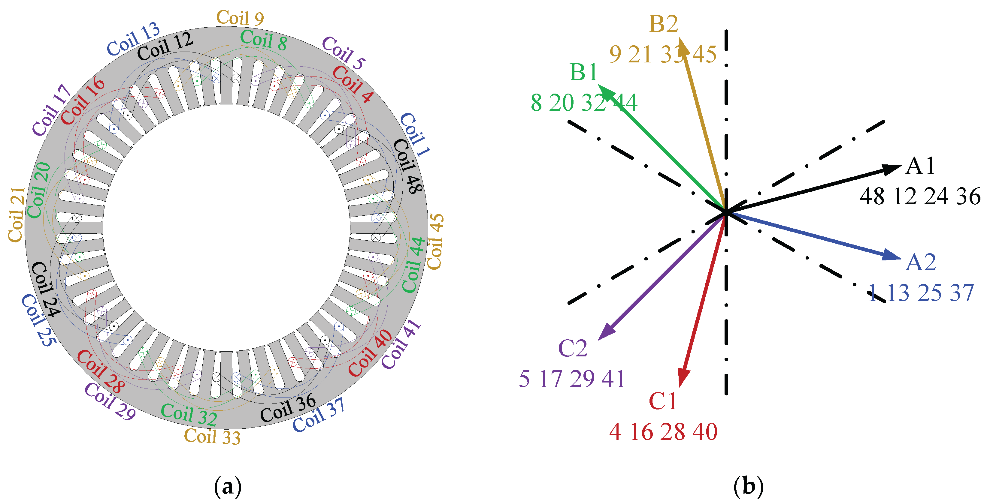
Figure 2.
Cross-sections of DTP PMSMs with IPM and AIPM rotors. (a) IPM. (b) AIPM.
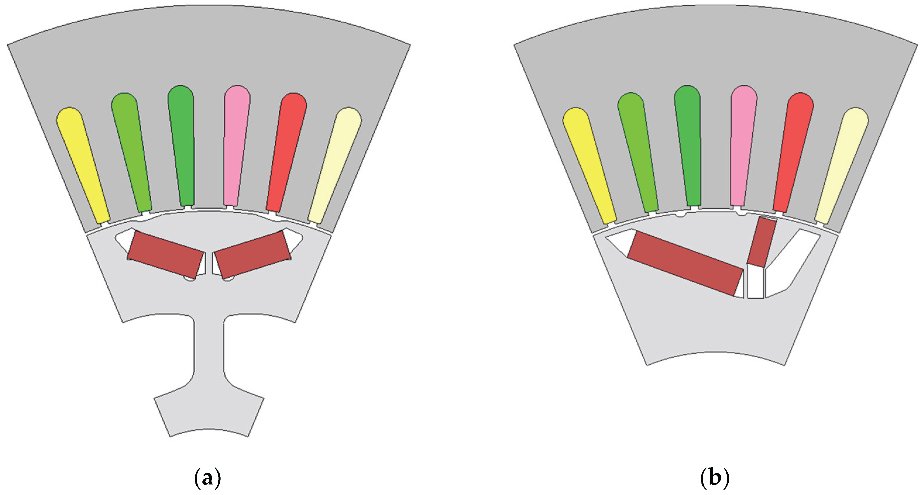
Figure 3.
Torque components of PMSMs with different rotors. (a) IPM (b) AIPM.
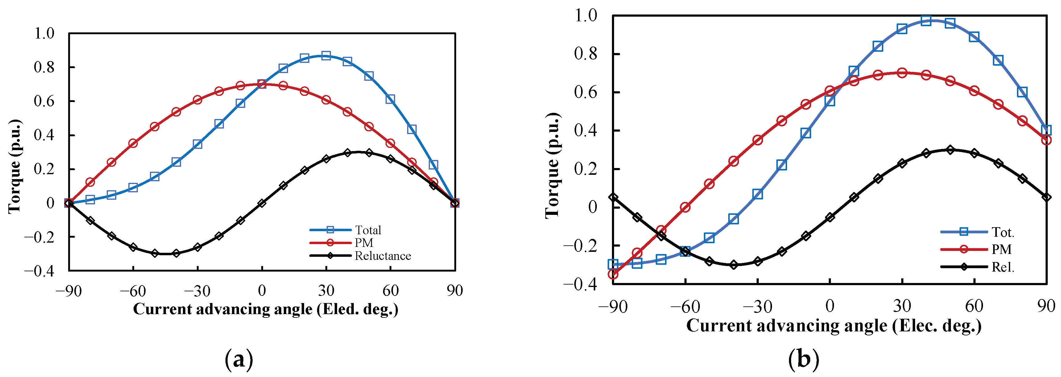
Figure 4.
Flux line distributions of DTP PMSMs with different rotors under open-circuit. (a) IPM. (b) AIPM.
Figure 4.
Flux line distributions of DTP PMSMs with different rotors under open-circuit. (a) IPM. (b) AIPM.

Figure 5.
Air-gap flux densities of DTP PMSMs machines with different rotors under open-circuit. (a) Waveforms. (b) Spectra (amplitude).
Figure 5.
Air-gap flux densities of DTP PMSMs machines with different rotors under open-circuit. (a) Waveforms. (b) Spectra (amplitude).
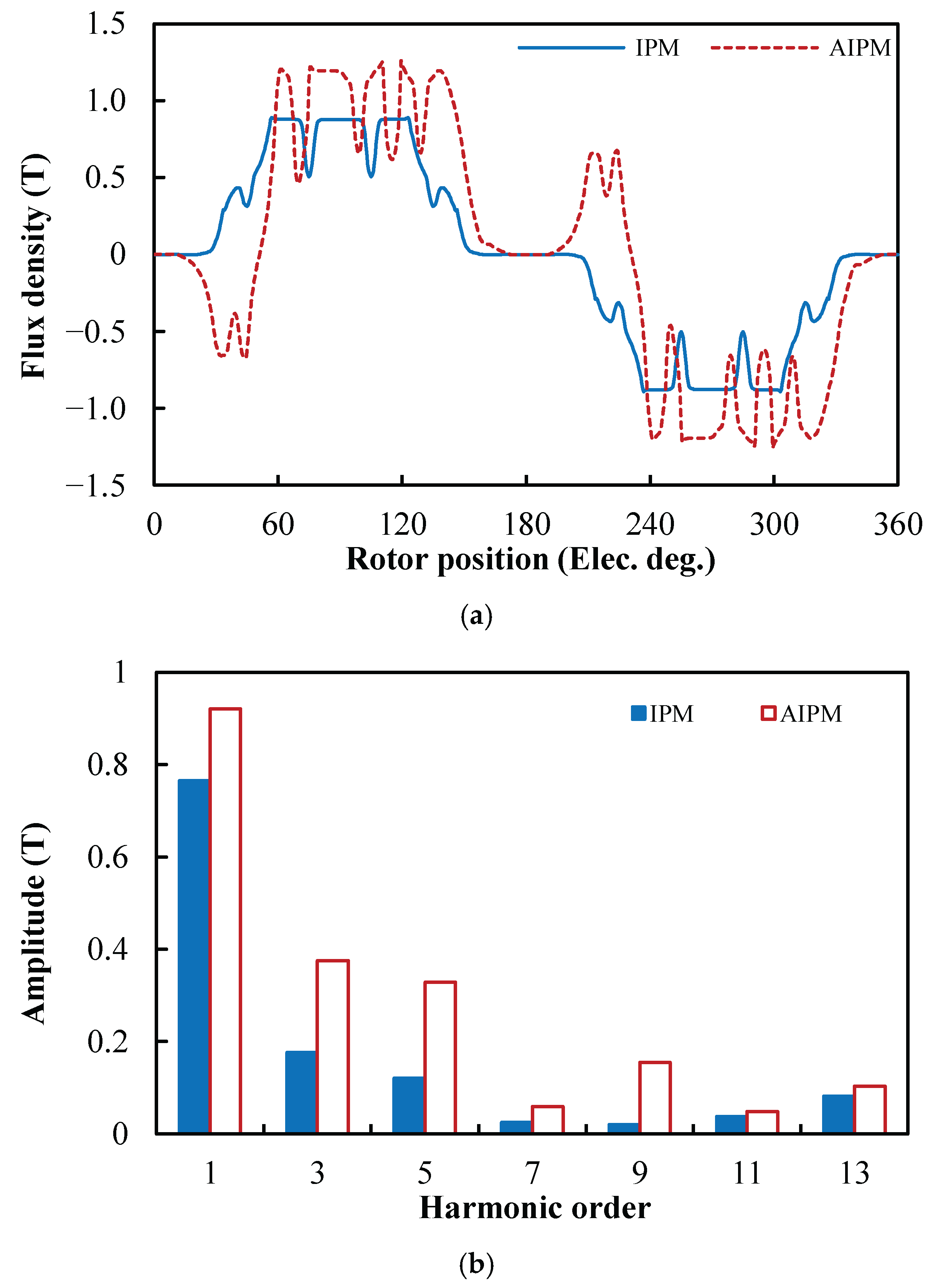
Figure 6.
Air-gap flux densities of DTP PMSMs machines with different rotors under open-circuit. (a) Waveforms. (b) Spectra (amplitude).
Figure 6.
Air-gap flux densities of DTP PMSMs machines with different rotors under open-circuit. (a) Waveforms. (b) Spectra (amplitude).
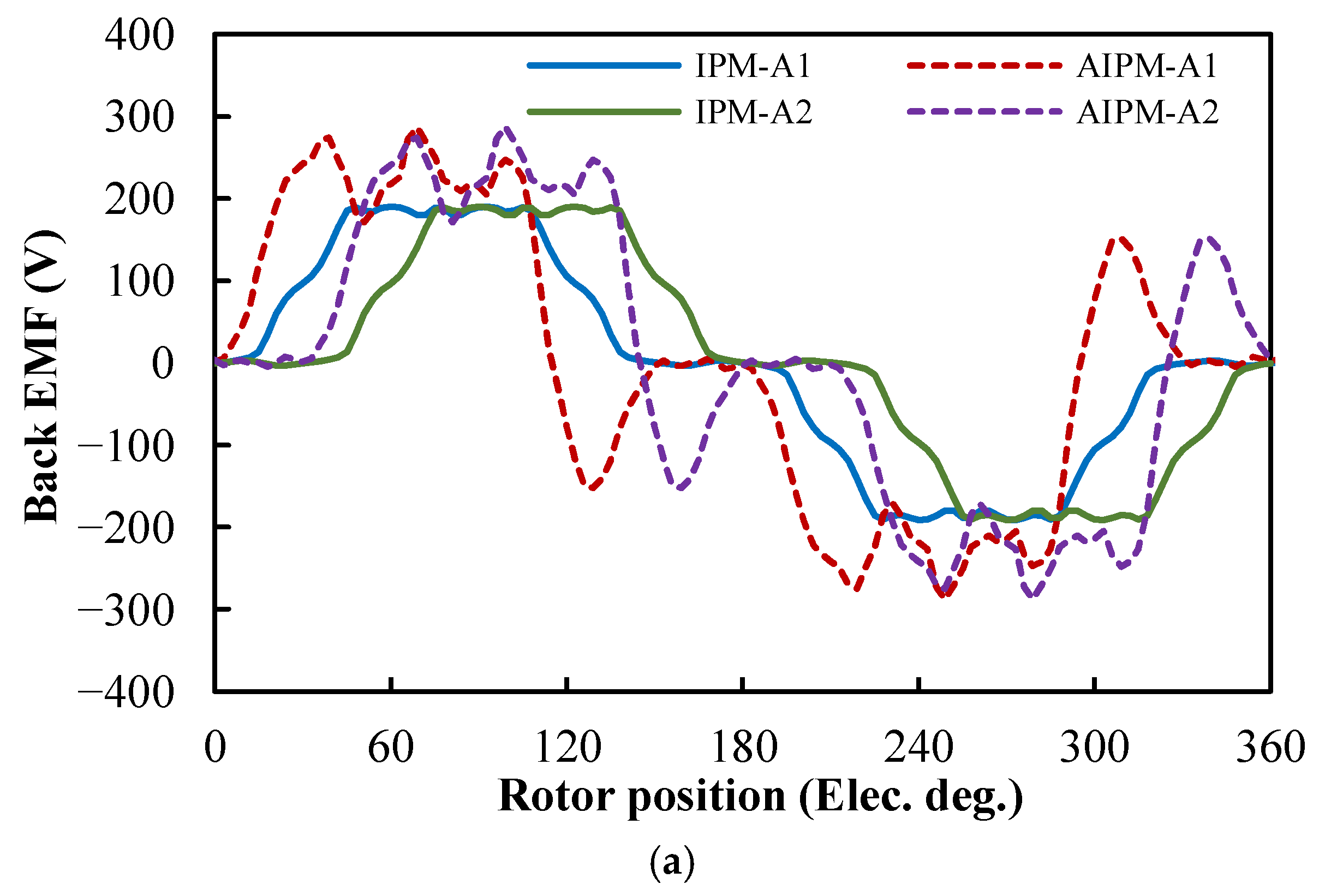
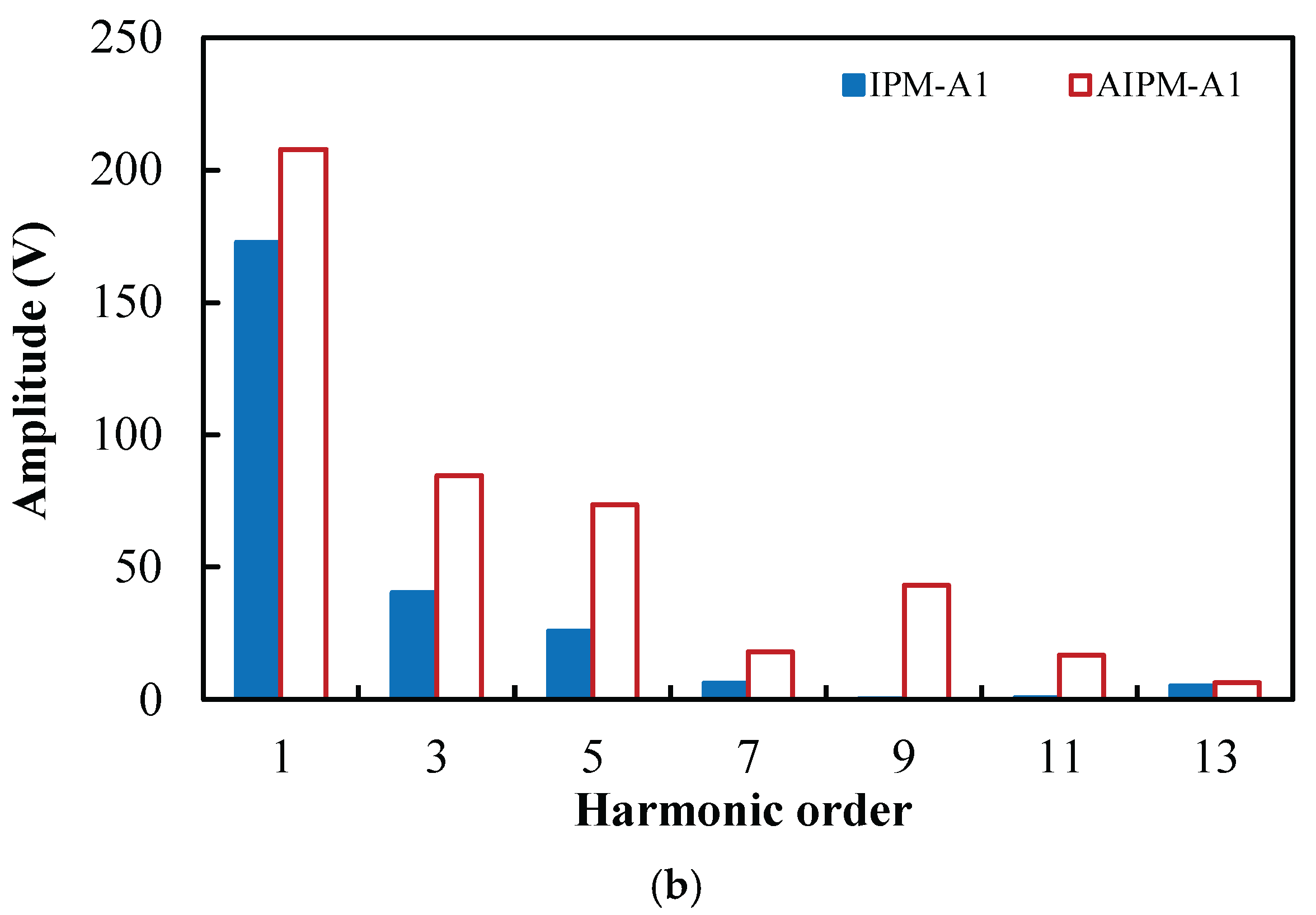
Figure 7.
Cogging torques of DTP PMSMs with different rotors. (a) Waveforms. (b) Spectra.
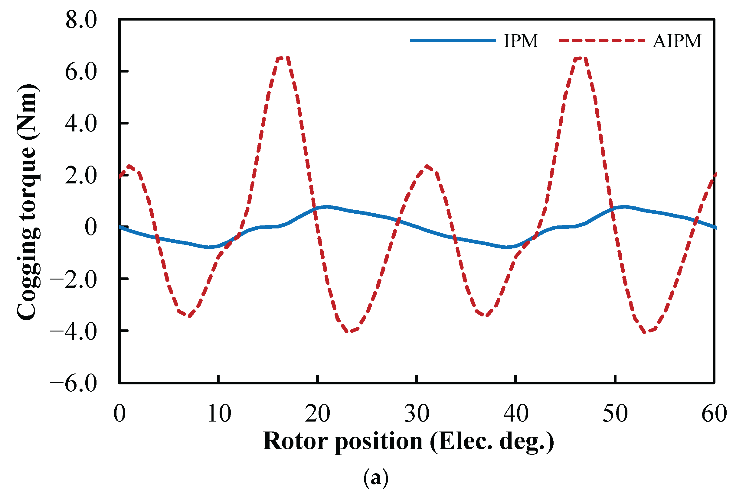
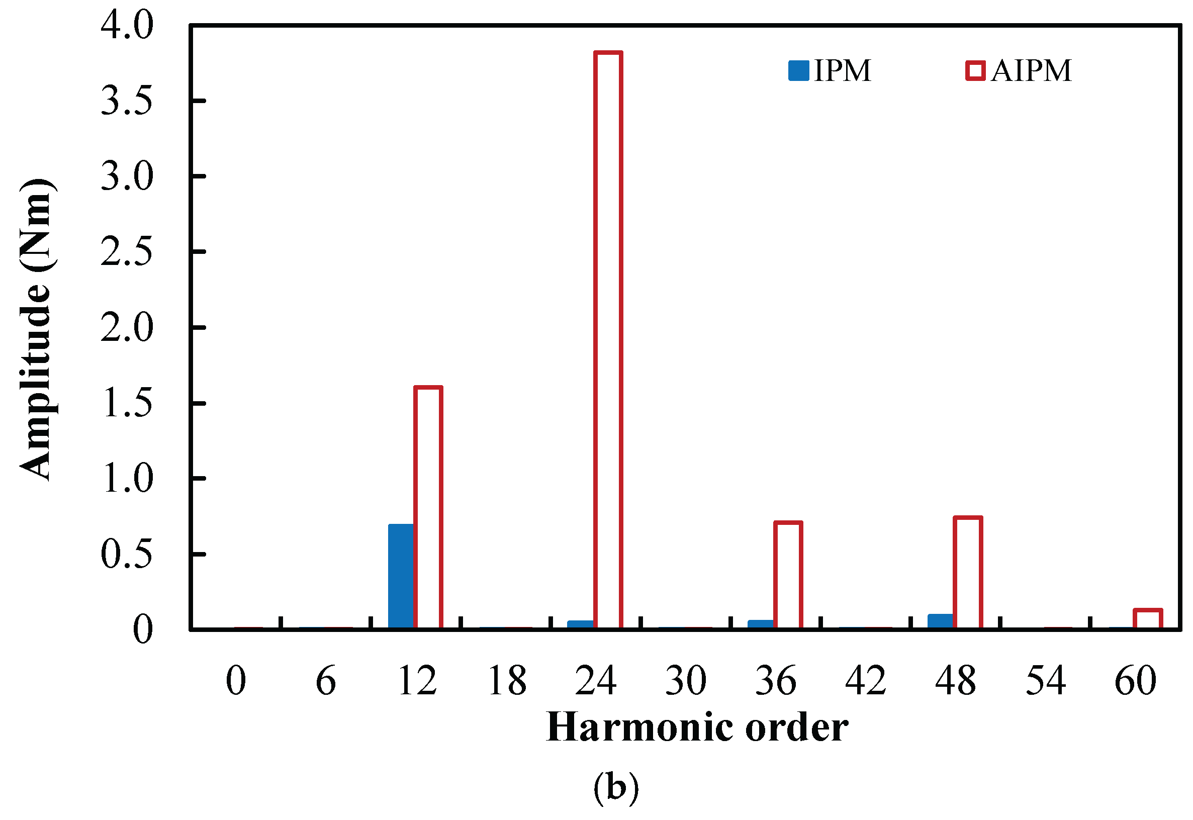
Figure 8.
Torque component-current advancing angle characteristics of DTP PMSMs with IPM and AIPM rotors (IA1 = 118Apk).
Figure 8.
Torque component-current advancing angle characteristics of DTP PMSMs with IPM and AIPM rotors (IA1 = 118Apk).
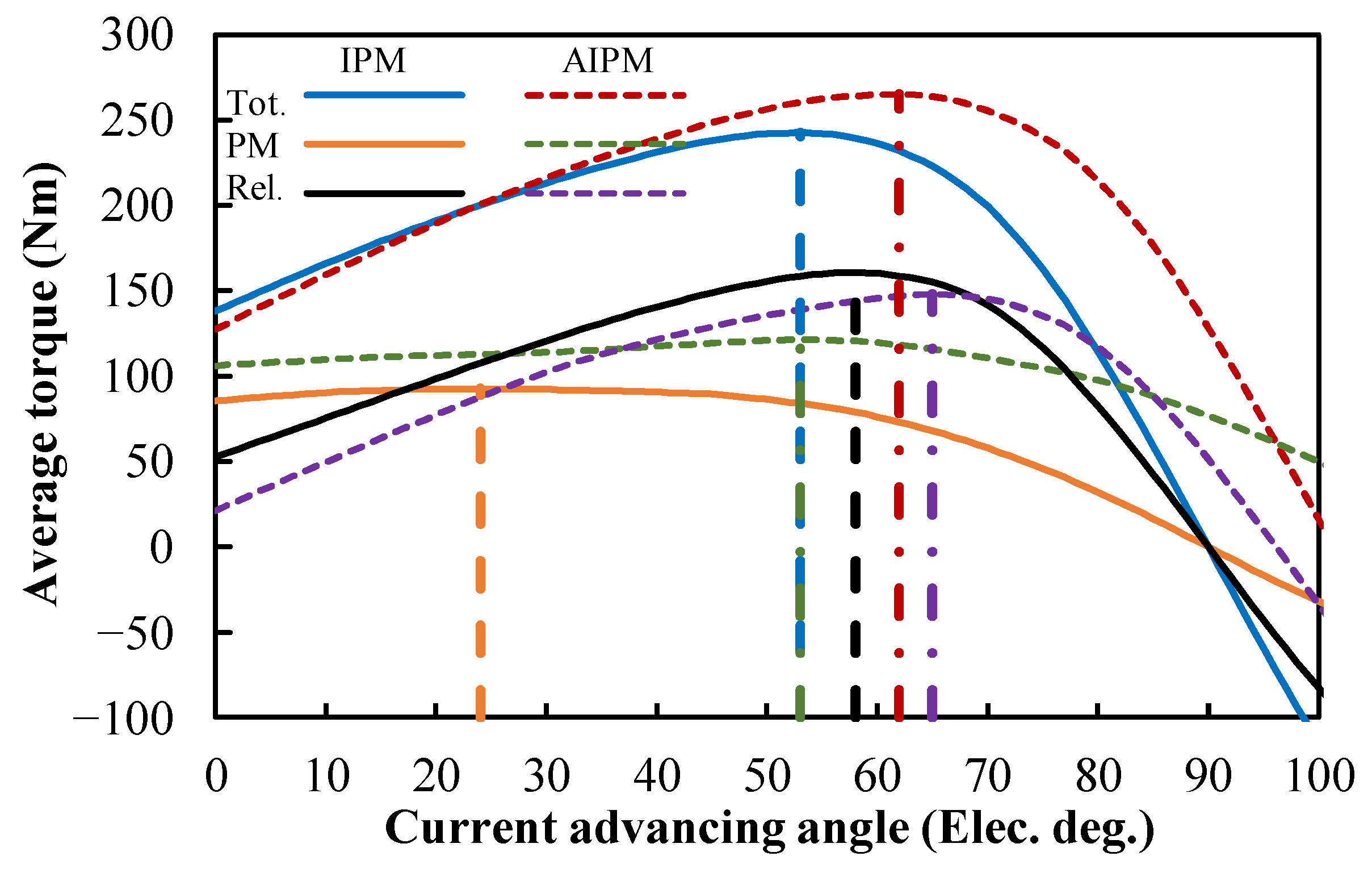
Figure 9.
Instantaneous torque waveforms and spectra of DTP PMSMs with IPM and AIPM rotors (IA1 = 118Apk). (a) Waveforms. (b) Spectra.
Figure 9.
Instantaneous torque waveforms and spectra of DTP PMSMs with IPM and AIPM rotors (IA1 = 118Apk). (a) Waveforms. (b) Spectra.
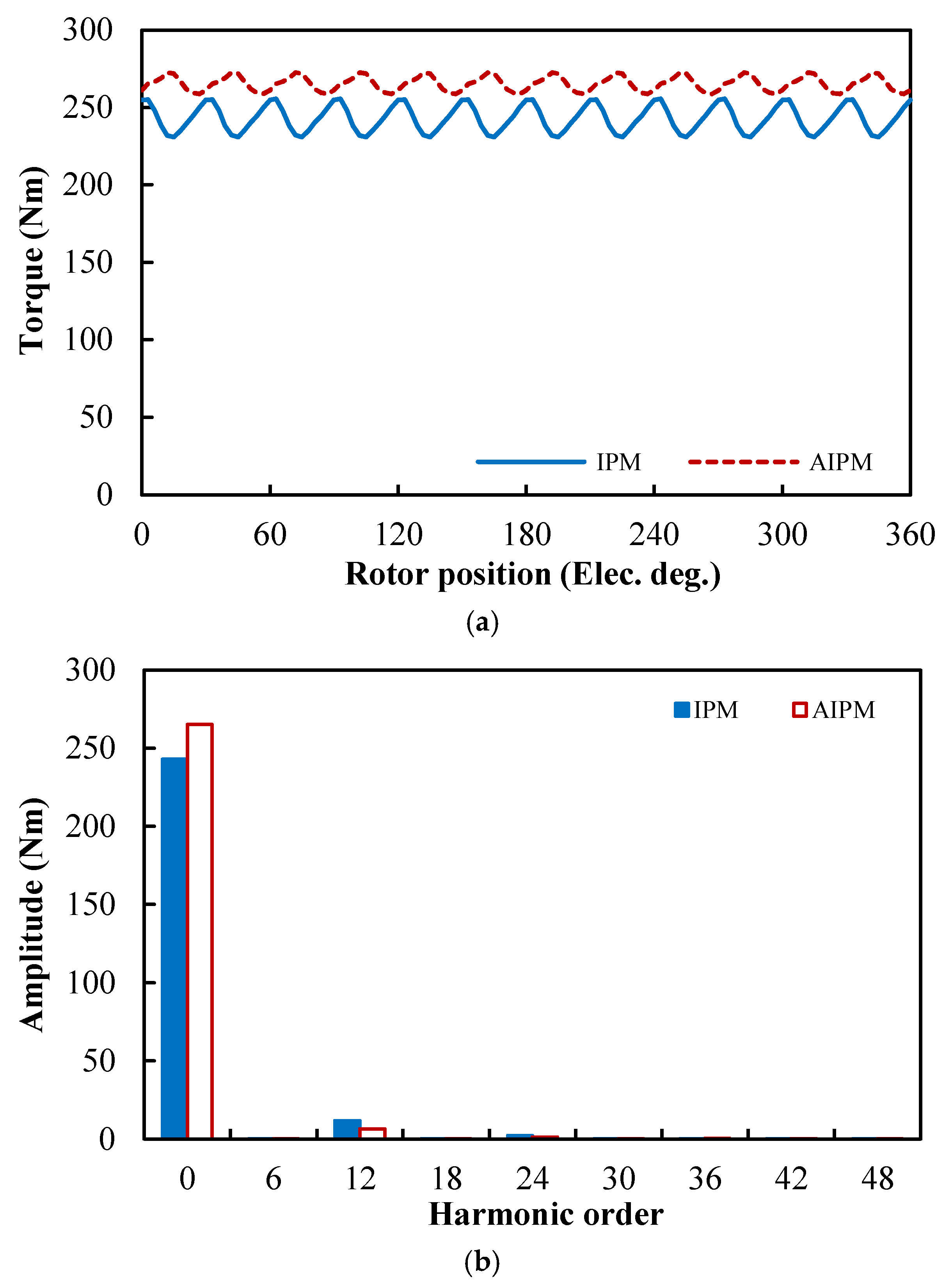
Figure 10.
Variations of torque characteristics with phase current amplitude in DTP PMSMs with IPM and AIPM rotors. (a) Average torque. (b) Torque ripple, (c) Average torque improvement.
Figure 10.
Variations of torque characteristics with phase current amplitude in DTP PMSMs with IPM and AIPM rotors. (a) Average torque. (b) Torque ripple, (c) Average torque improvement.
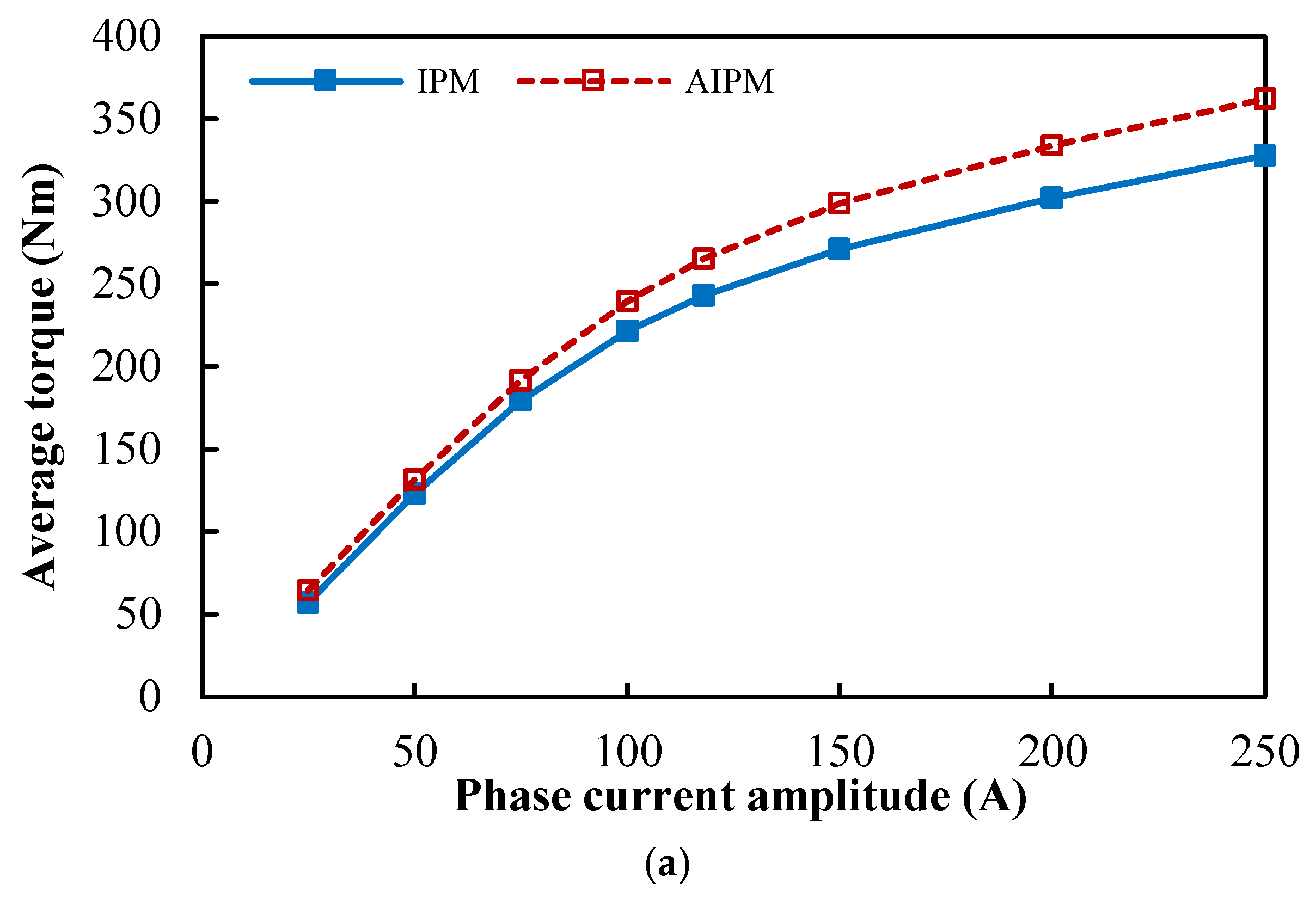
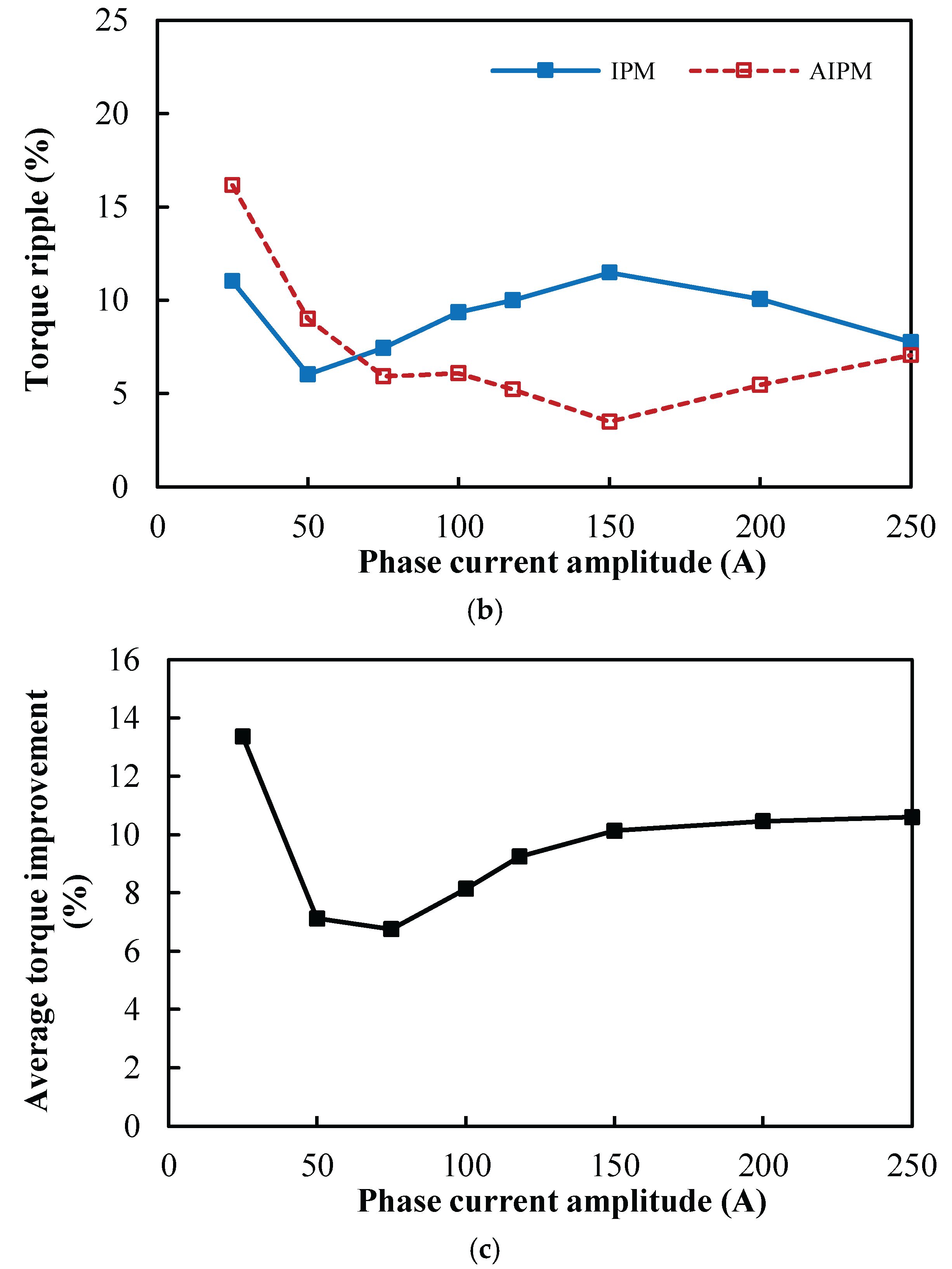
Figure 11.
Torque and power-speed curves of DTP PMSMs with IPM and AIPM rotors. (a) Torque-speed curves. (b) Power-speed curves.
Figure 11.
Torque and power-speed curves of DTP PMSMs with IPM and AIPM rotors. (a) Torque-speed curves. (b) Power-speed curves.
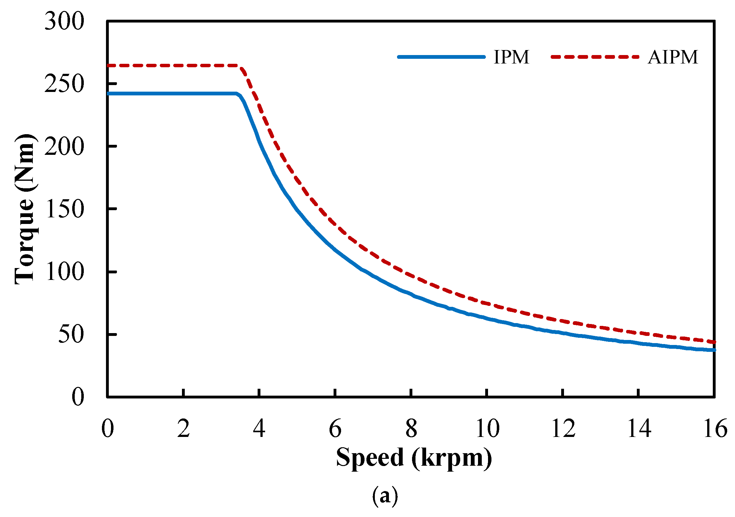
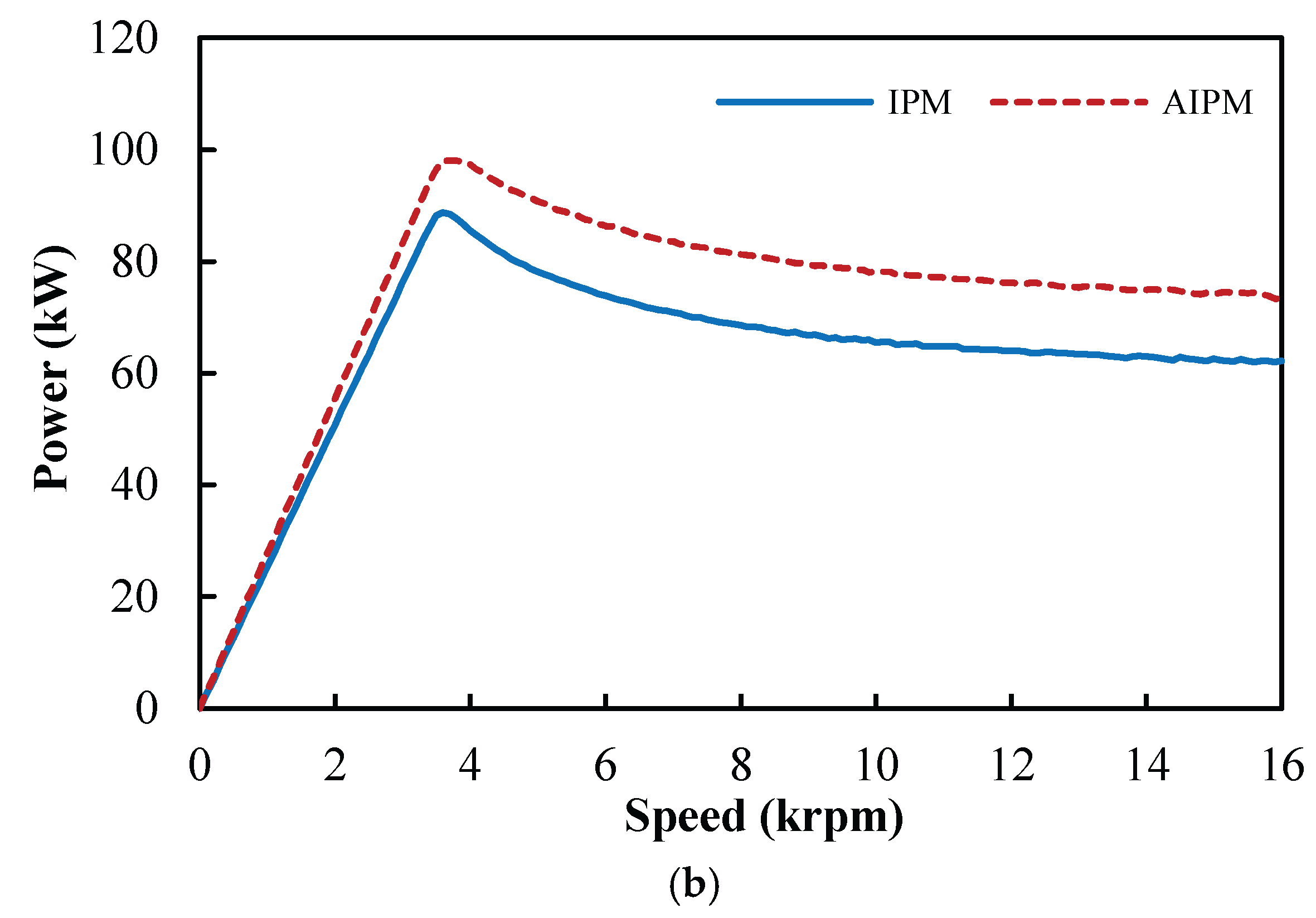
Figure 12.
Current-speed curves of DTP PMSMs with IPM and AIPM rotors. (a) Id- and Iq-speed curves. (b) Ia-speed curves.
Figure 12.
Current-speed curves of DTP PMSMs with IPM and AIPM rotors. (a) Id- and Iq-speed curves. (b) Ia-speed curves.
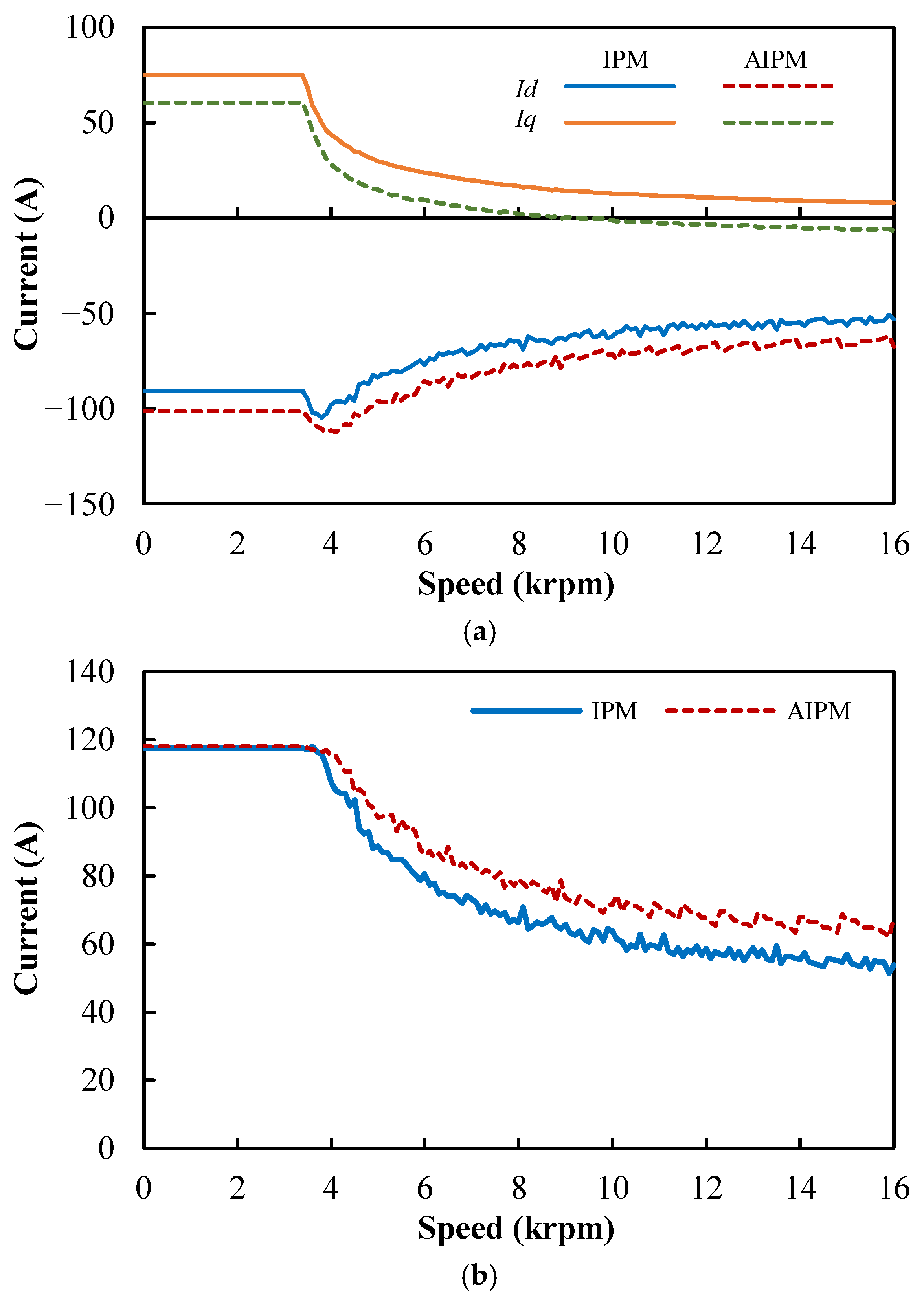
Figure 13.
Copper loss maps of DTP PMSMs with IPM and AIPM rotors. (a) IPM. (b) AIPM.
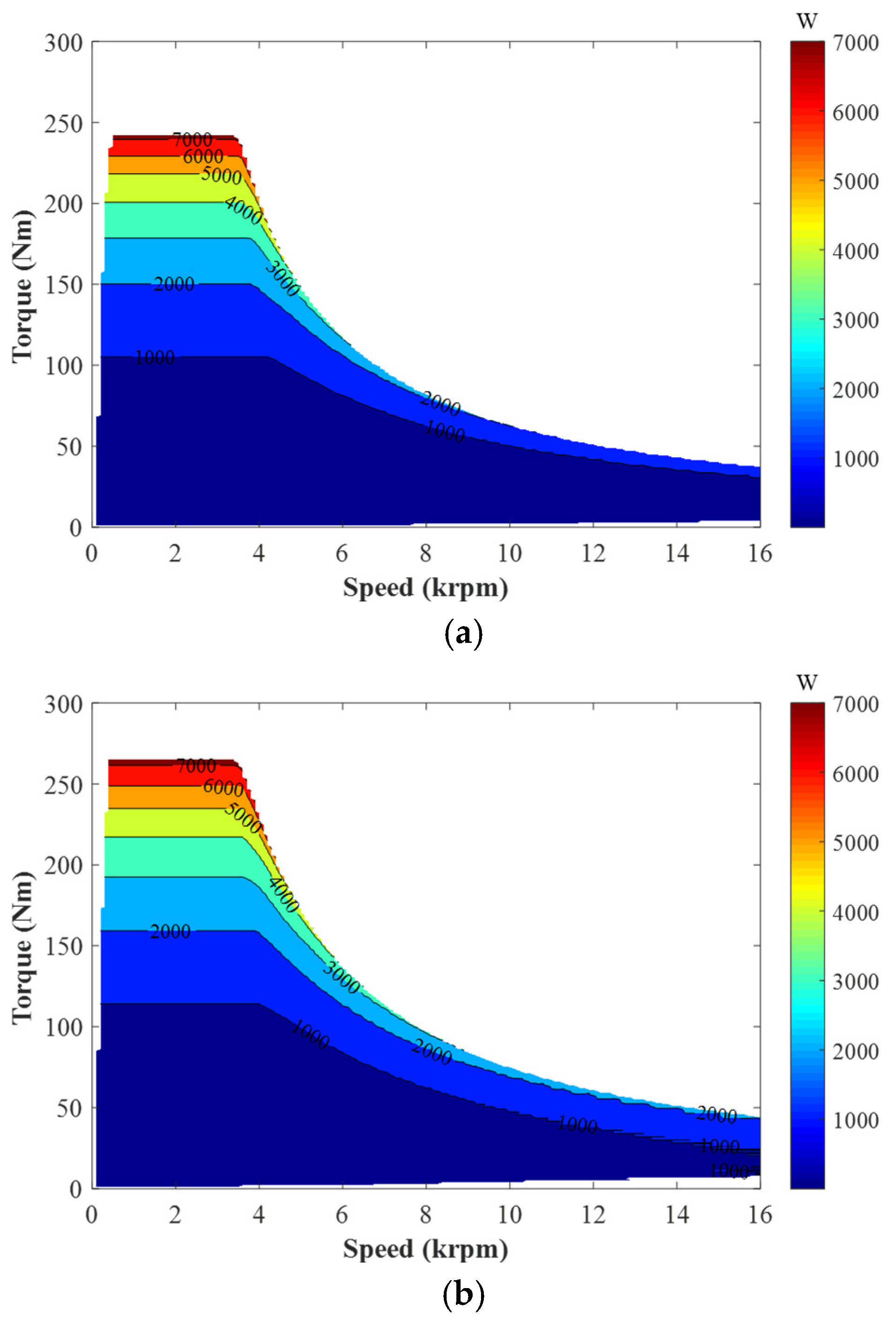
Figure 14.
Iron loss maps of DTP PMSMs with IPM and AIPM rotors. (a) IPM. (b) AIPM.
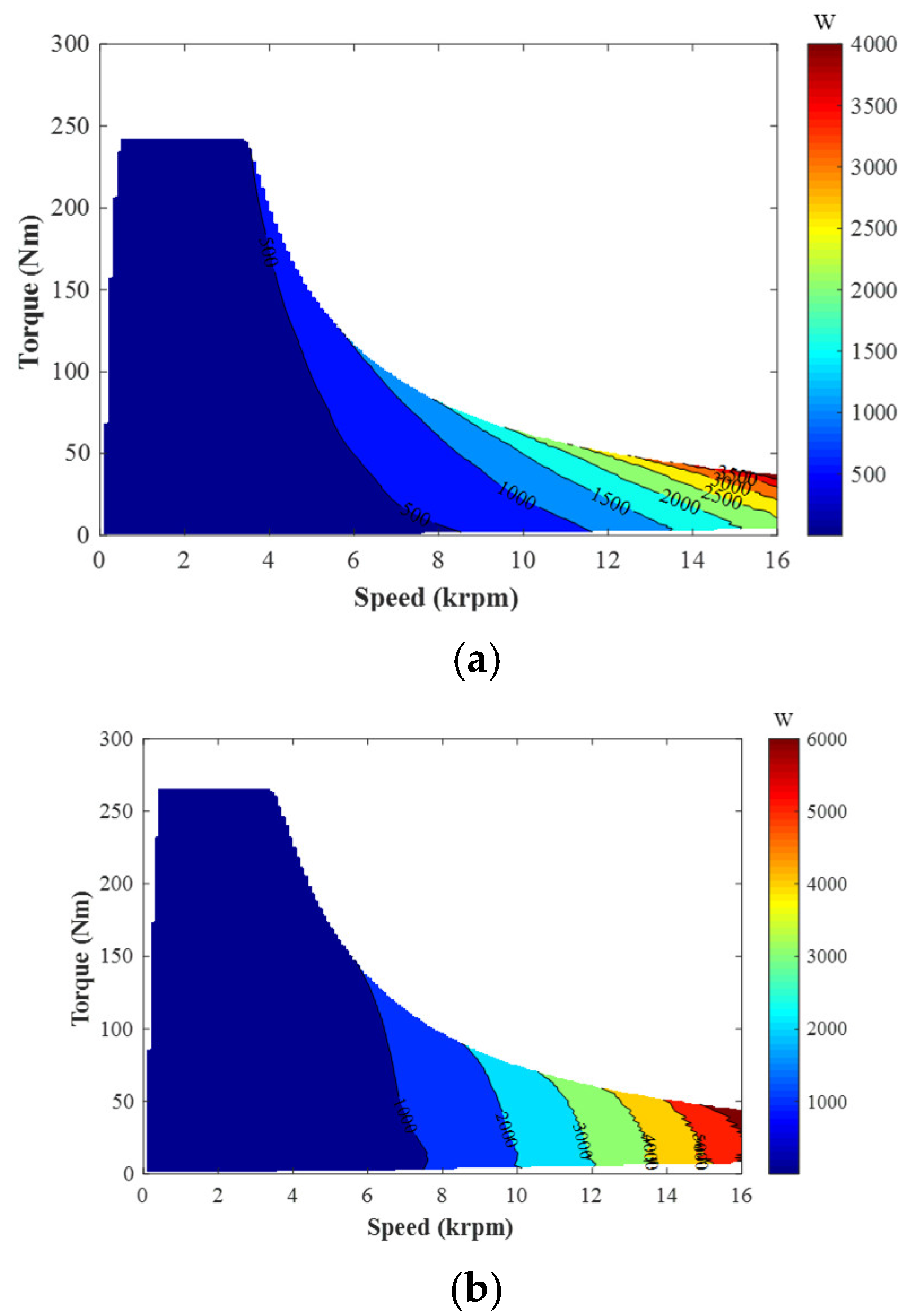
Figure 15.
Mechanical loss of DTP PMSMs with IPM and AIPM rotors.
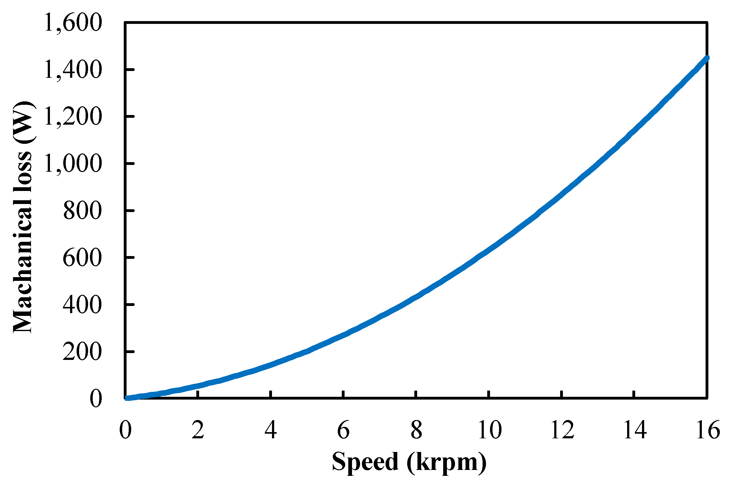
Figure 16.
Total loss maps of DTP PMSMs with IPM and AIPM rotors. (a) IPM. (b) AIPM. (c) Total loss difference (AIPM−IPM).
Figure 16.
Total loss maps of DTP PMSMs with IPM and AIPM rotors. (a) IPM. (b) AIPM. (c) Total loss difference (AIPM−IPM).
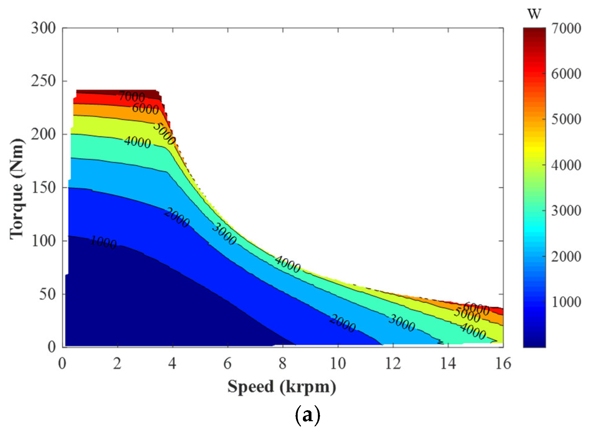
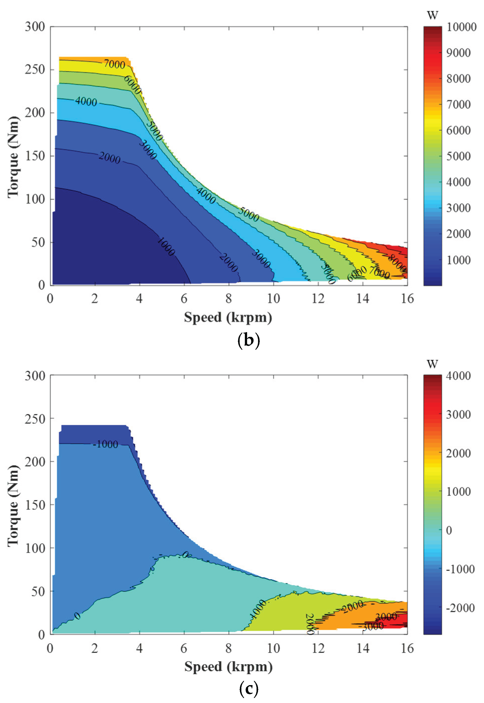
Figure 17.
Variations of iron losses with phase current amplitude in DTP PMSMs with IPM and AIPM rotors.
Figure 17.
Variations of iron losses with phase current amplitude in DTP PMSMs with IPM and AIPM rotors.
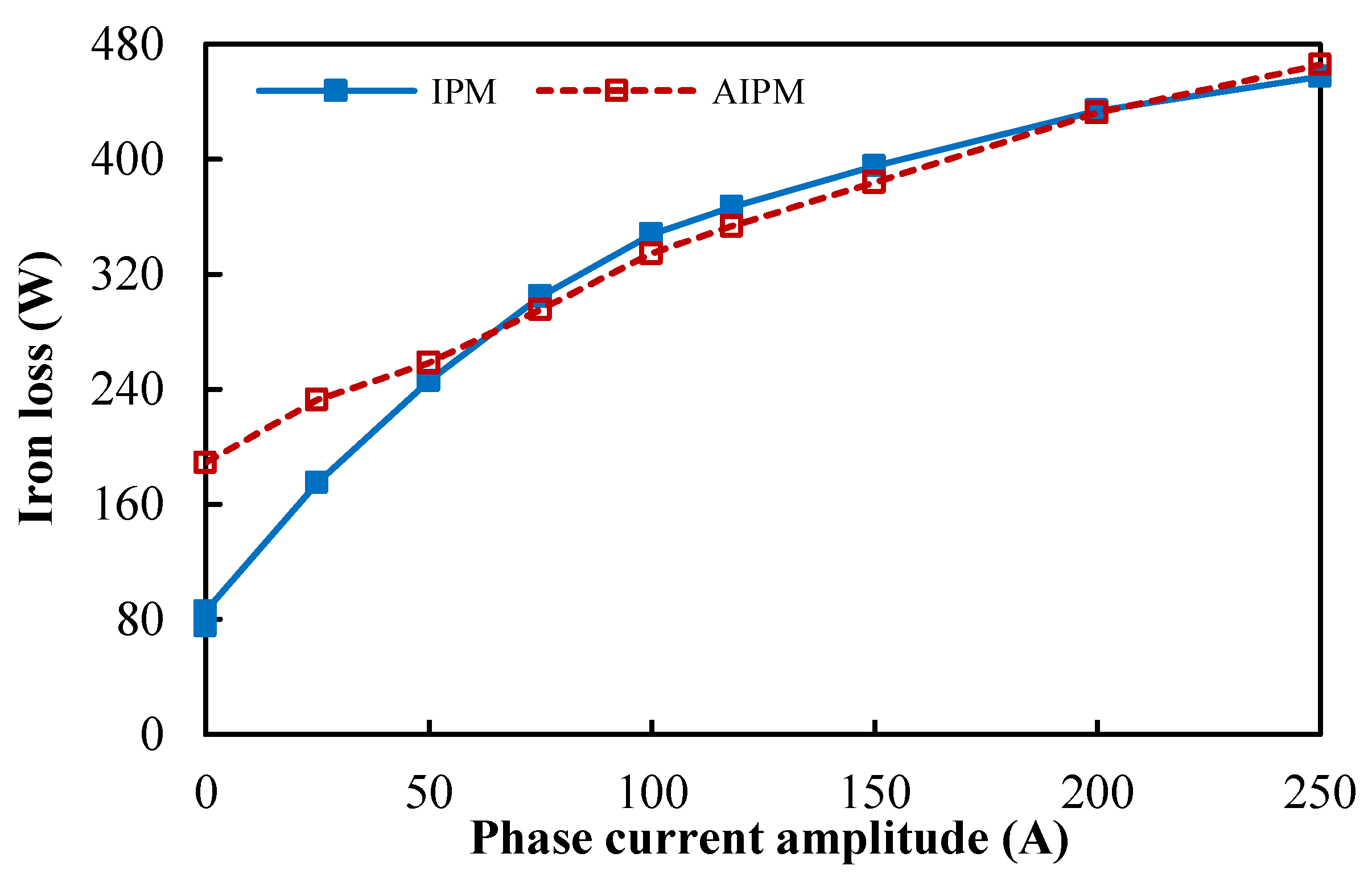
Figure 18.
Air-gap flux densities of DTP PMSMs machines with different rotors under full-load (IA1 = 118Apk). (a) Waveforms. (b) Spectra.
Figure 18.
Air-gap flux densities of DTP PMSMs machines with different rotors under full-load (IA1 = 118Apk). (a) Waveforms. (b) Spectra.
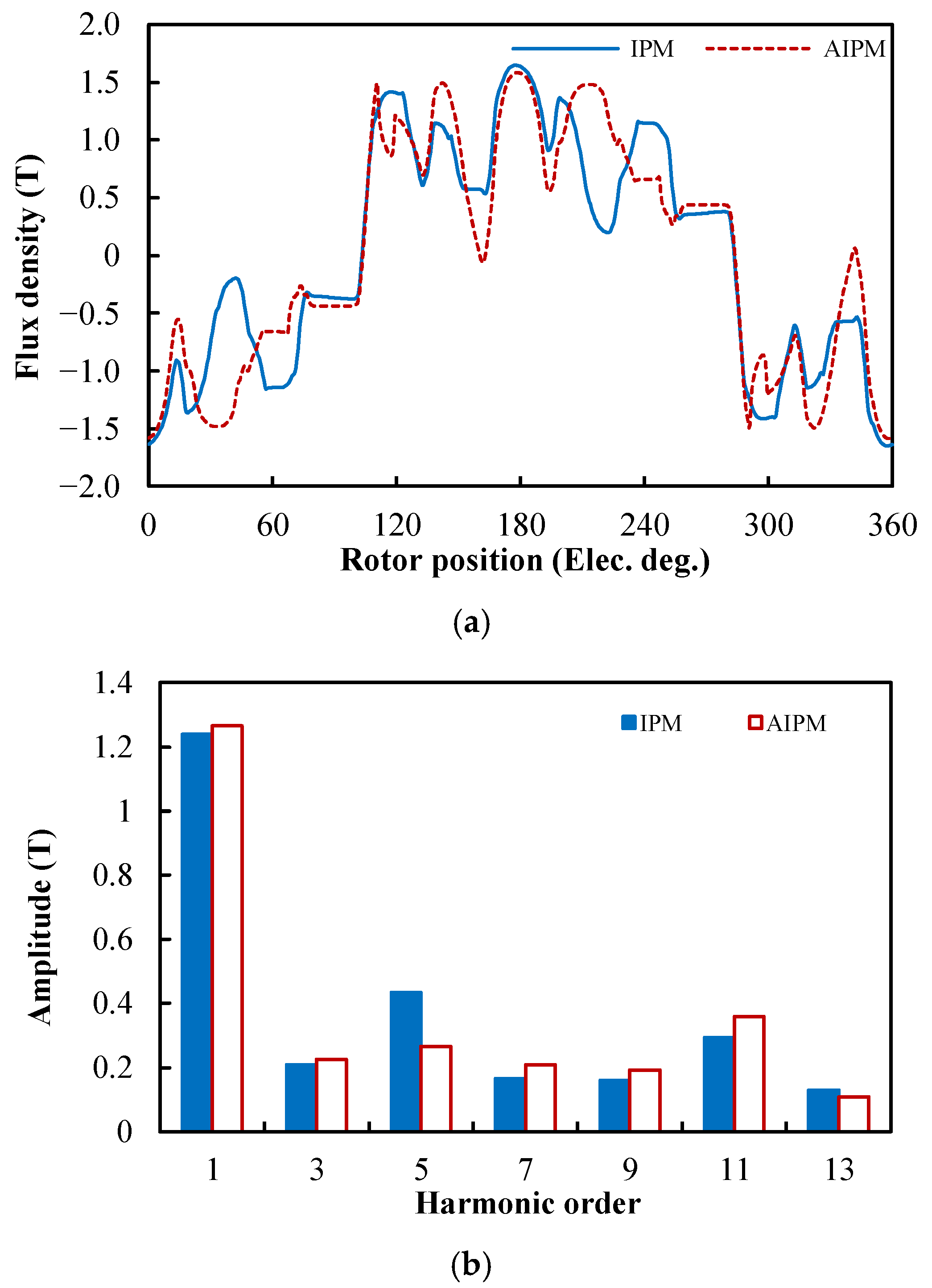
Figure 19.
Efficiency maps of DTP PMSMs with IPM and AIPM rotors. (a) IPM. (b) AIPM. (c) Efficiency difference (AIPM−IPM).
Figure 19.
Efficiency maps of DTP PMSMs with IPM and AIPM rotors. (a) IPM. (b) AIPM. (c) Efficiency difference (AIPM−IPM).
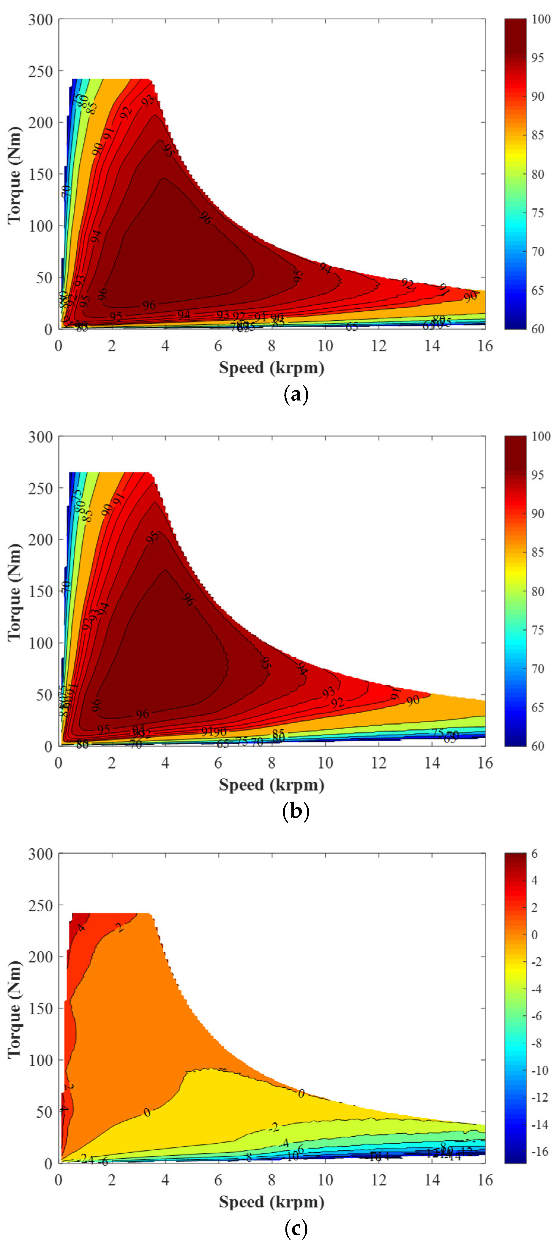
Figure 20.
Torque component-current advancing angle characteristics of DTP PMSMs with IPM and AIPM rotors under single three-phase OC (IA1 = 118 Apk).
Figure 20.
Torque component-current advancing angle characteristics of DTP PMSMs with IPM and AIPM rotors under single three-phase OC (IA1 = 118 Apk).
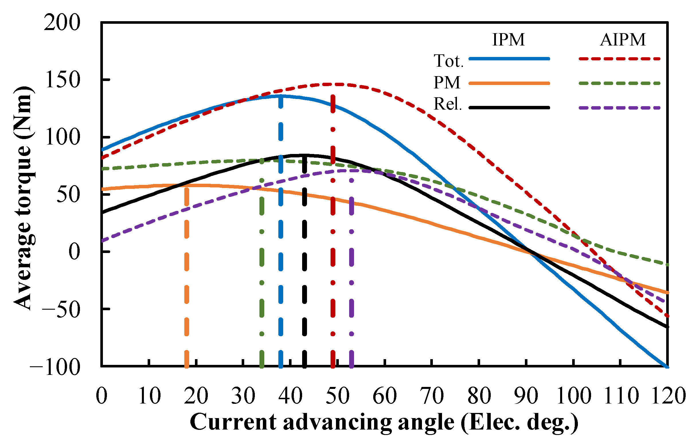
Figure 21.
Instantaneous torque waveforms and spectra of DTP PMSMs with IPM and AIPM rotors under three-phase OC (IA1 = 118Apk). (a) Waveforms. (b) Spectra.
Figure 21.
Instantaneous torque waveforms and spectra of DTP PMSMs with IPM and AIPM rotors under three-phase OC (IA1 = 118Apk). (a) Waveforms. (b) Spectra.
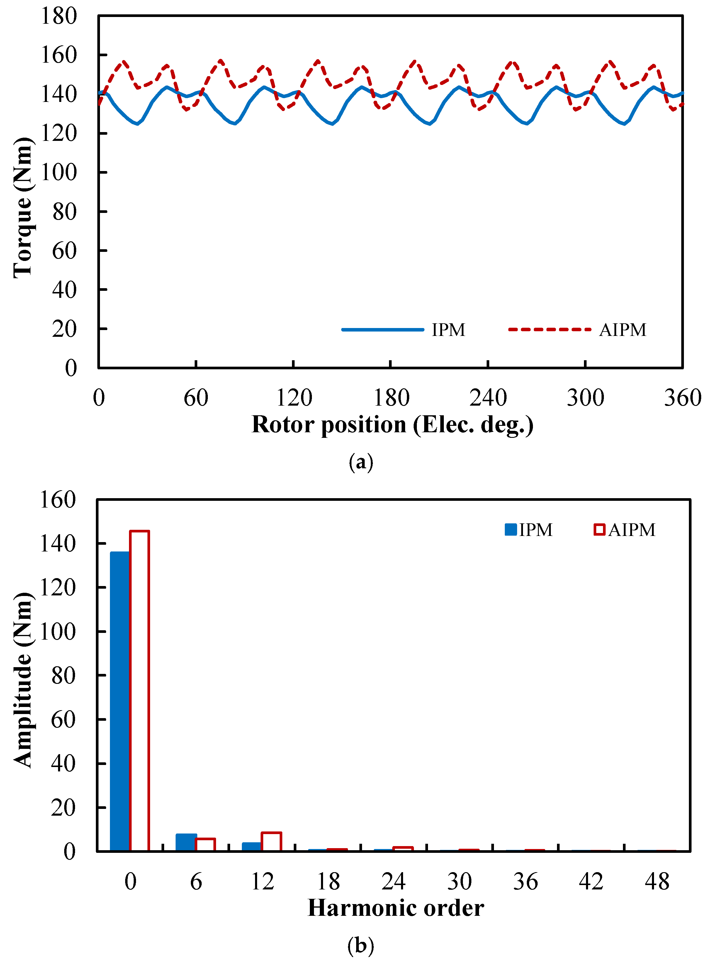
Figure 22.
Variations of torque characteristics with phase current amplitude in DTP PMSMs with IPM and AIPM rotors under three-phase OC. (a) Average torque. (b) Torque ripple. (c) Average torque improvement.
Figure 22.
Variations of torque characteristics with phase current amplitude in DTP PMSMs with IPM and AIPM rotors under three-phase OC. (a) Average torque. (b) Torque ripple. (c) Average torque improvement.
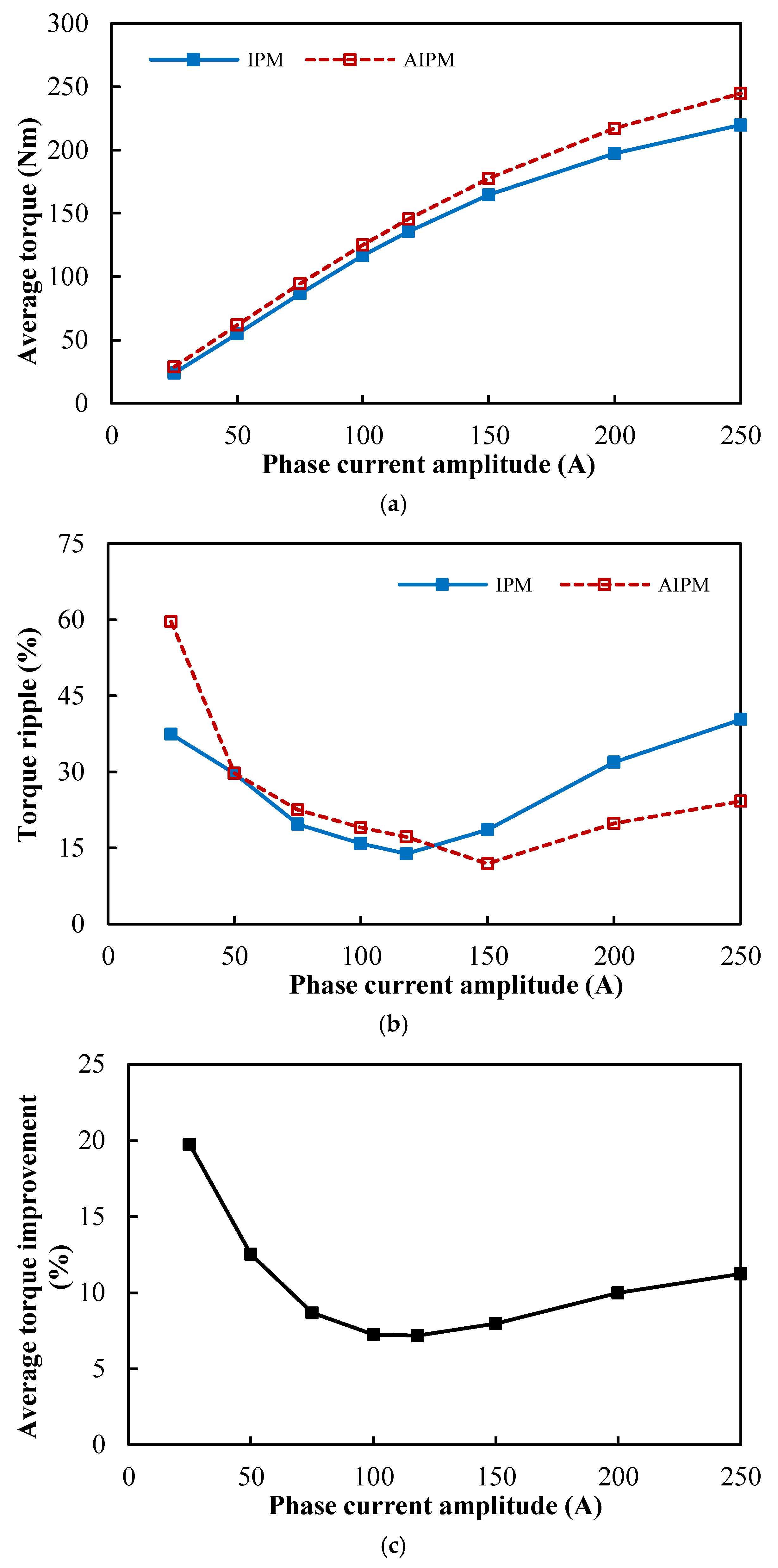
Figure 23.
Pictures of prototype DTP PMSM with AIPM rotor. (a) Stator lamination. (b) Rotor lamination. (c) Stator. (d) Rotor.
Figure 23.
Pictures of prototype DTP PMSM with AIPM rotor. (a) Stator lamination. (b) Rotor lamination. (c) Stator. (d) Rotor.
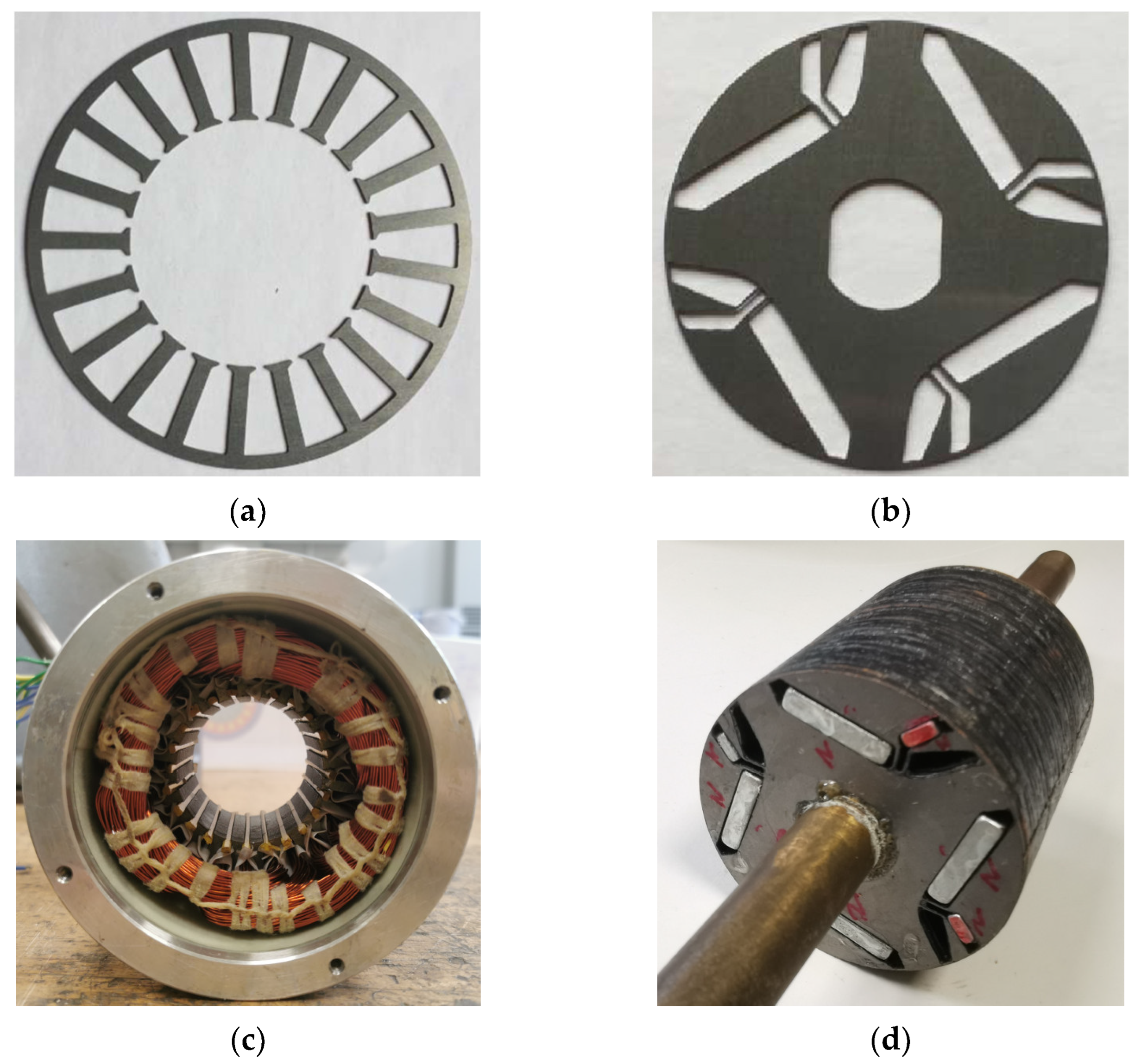
Figure 24.
Picture of test rig.
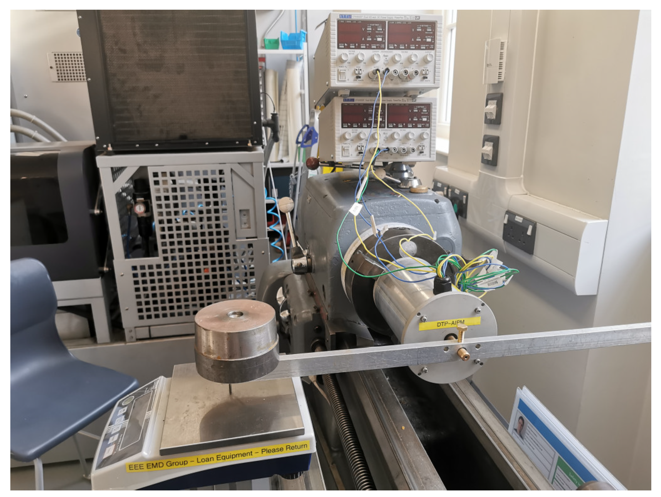
Figure 25.
Phase back EMF comparison between FE predicted and measured results at 200 rpm. (a) Waveforms. (b) Spectra.
Figure 25.
Phase back EMF comparison between FE predicted and measured results at 200 rpm. (a) Waveforms. (b) Spectra.
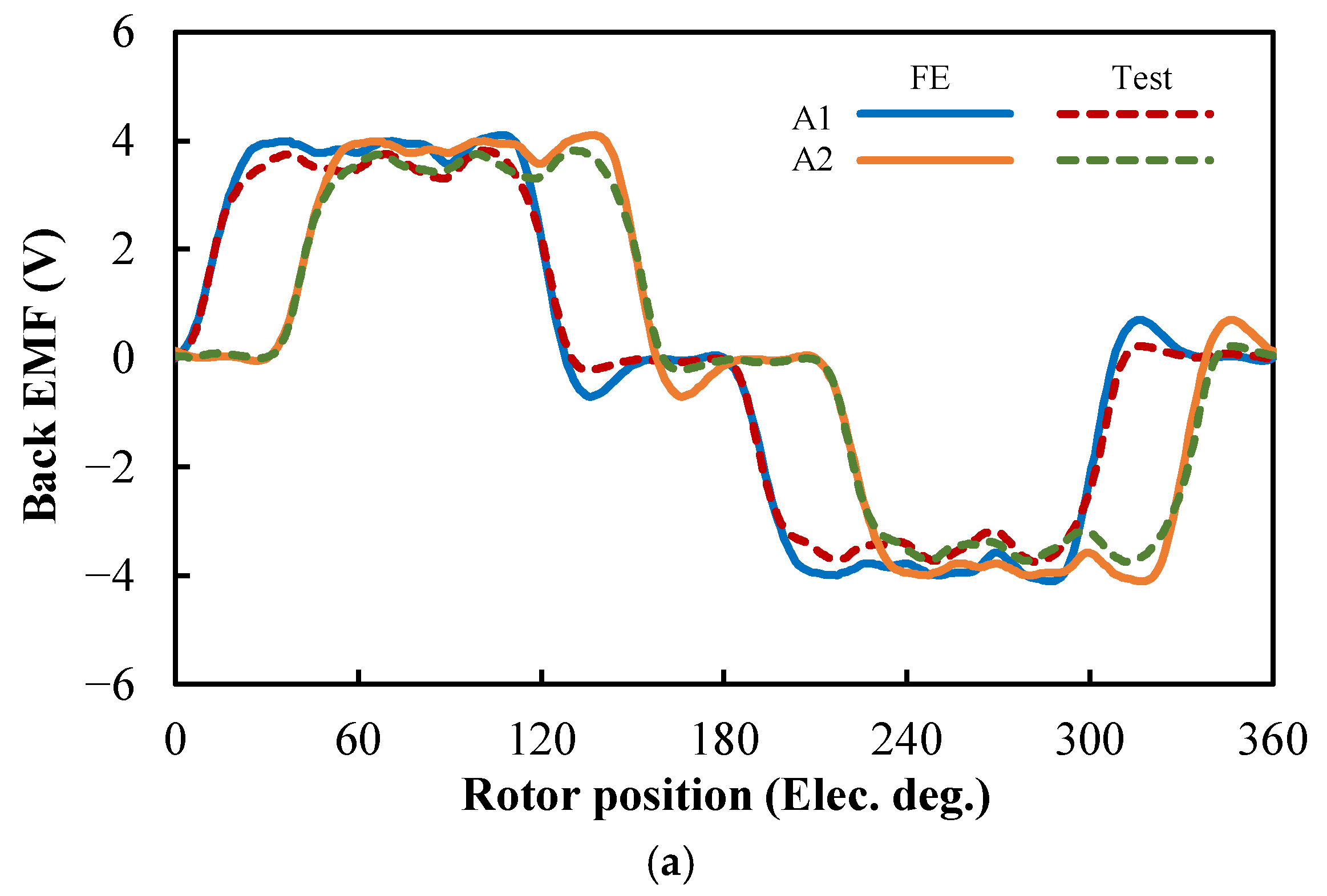
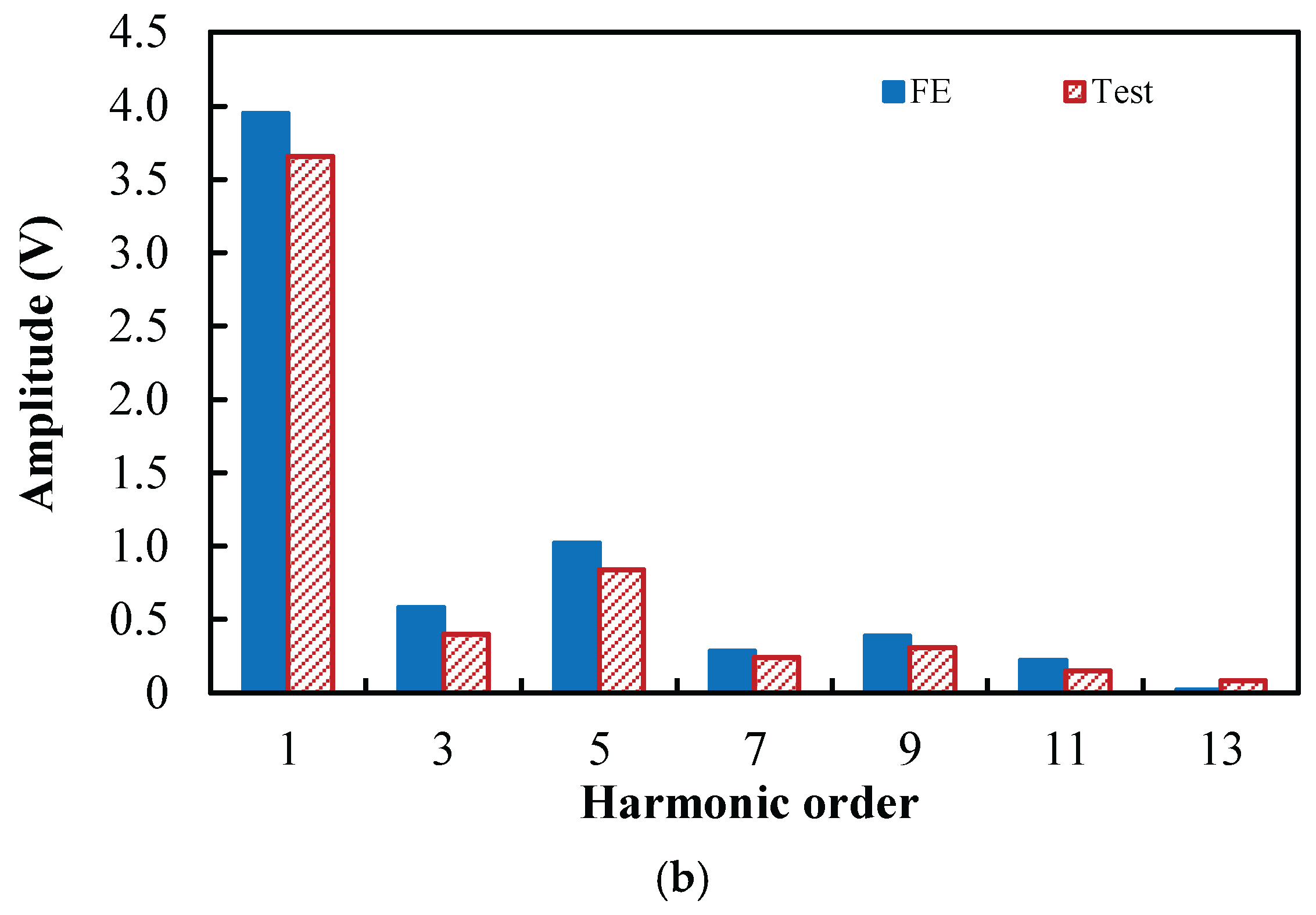
Figure 26.
Cogging torque comparison between FE predicted and measured results. (a) Waveforms. (b) Spectra.
Figure 26.
Cogging torque comparison between FE predicted and measured results. (a) Waveforms. (b) Spectra.
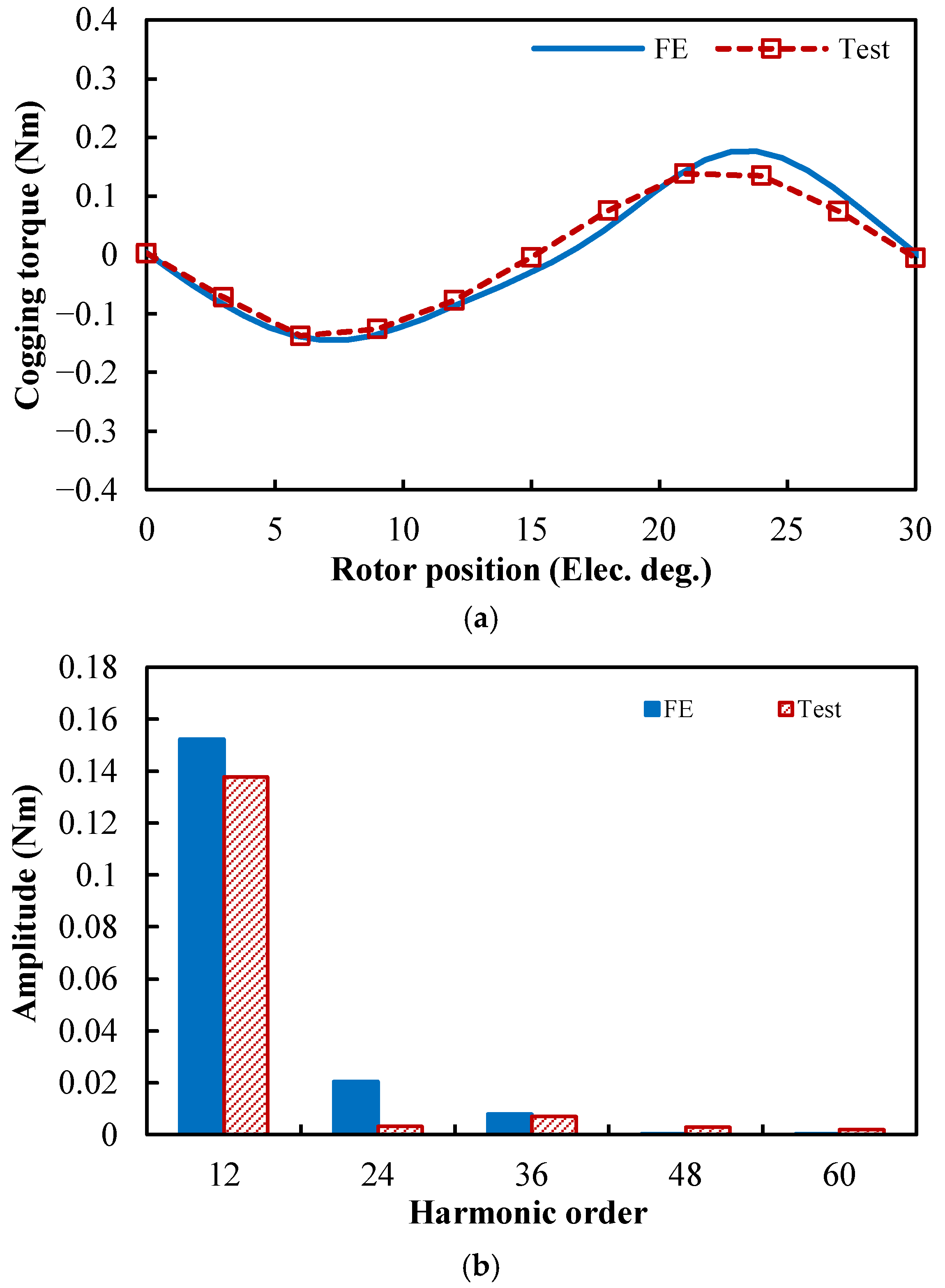
Figure 27.
Phase currents for DTP PMSM.
Figure 28.
Static torque comparison between FE predicted and measured results with different Idc values. (a) Waveforms. (b) Spectra.
Figure 28.
Static torque comparison between FE predicted and measured results with different Idc values. (a) Waveforms. (b) Spectra.
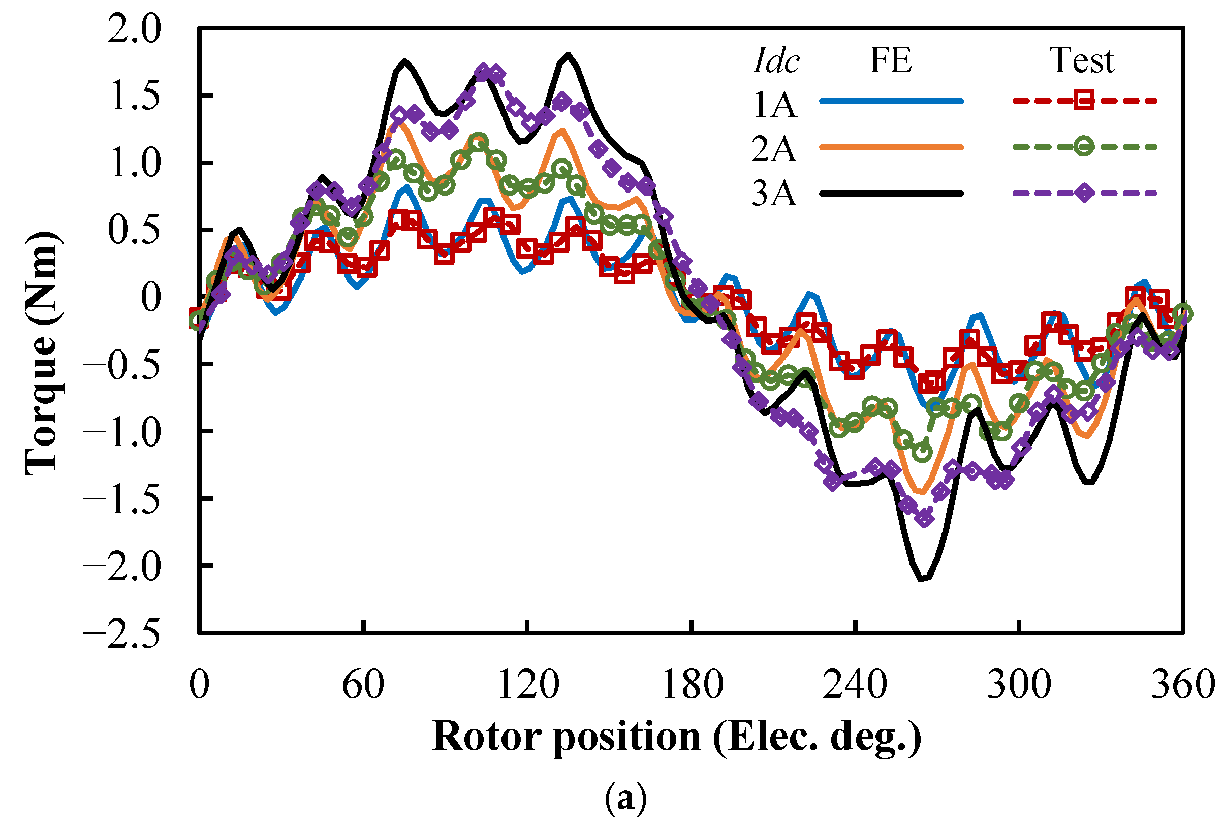
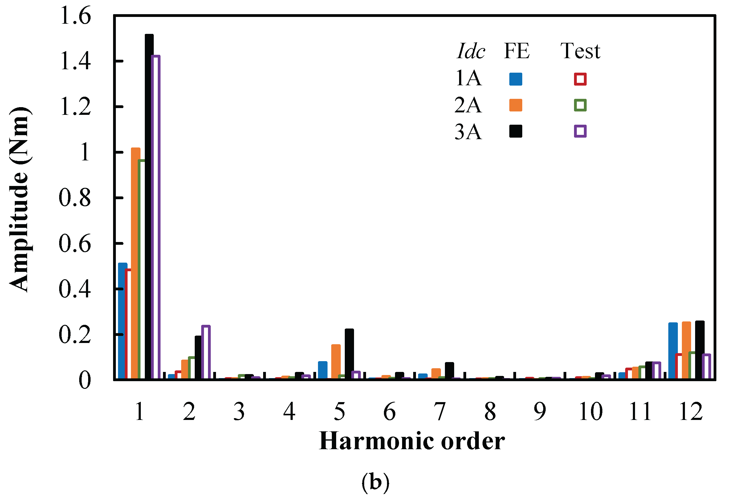
Figure 29.
Variations of FE predicted and measured fundamental static torque amplitudes with Idc.
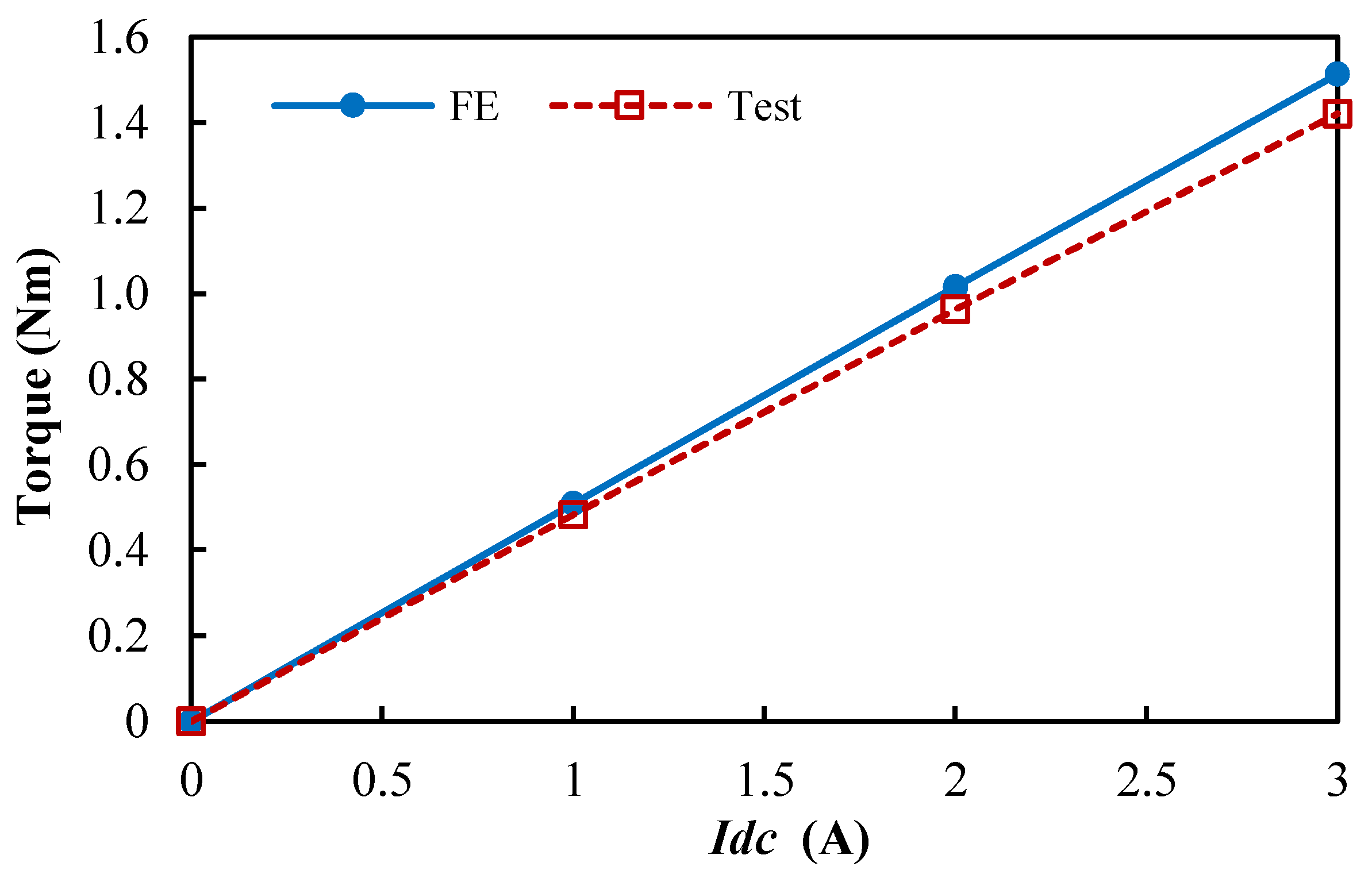

Table 1.
Main design specifications of benchmark PMSM.
| Parameters | Values |
|---|---|
| Stator | |
| Stator OD, mm | 264 |
| Stator ID, mm | 161.9 |
| Stack length, mm | 50.8 |
| Slot depth, mm | 30.9 |
| Slot opening, mm | 1.88 |
| IPM rotor | |
| Rotor OD, mm | 160.4 |
| Rotor ID, mm | 51 |
| Stack length, mm | 50.8 |
| PM length, mm | 17.88 |
| PM thickness, mm | 7.16 |
| PM remanence, T | 1.2 |
| PM relative permeability | 1.05 |
| AIPM rotor | |
| Rotor OD, mm | 160.4 |
| Rotor ID, mm | 90 |
| Stack length, mm | 50.8 |
| Large PM length, mm | 28.3 |
| Large PM thickness, mm | 7.2 |
| Small PM length, mm | 12 |
| PM remanence, T | 1.2 |
| PM relative permeability | 1.05 |
Table 2.
Maximum torque components and optimal current advancing angles of DTP PMSMs with IPM and AIPM rotors (IA1 = 236 APK).
Table 2.
Maximum torque components and optimal current advancing angles of DTP PMSMs with IPM and AIPM rotors (IA1 = 236 APK).
| Torque component | Maximum value (Nm) | Optimal current advancing angle (°) | ||
| IPM | AIPM | IPM | AIPM | |
| Tot. torque | 242.77 | 265.22 | 53 | 62 |
| PM torque | 92.73 | 121.40 | 24 | 53 |
| Rel. torque | 160.70 | 147.87 | 58 | 65 |
Table 3.
Torque characteristics of DTP IPM and AIPM machines (IA1 = 118APK).
| IPM | AIPM | Change | |
| Average torque (Nm) | 242.77 | 265.22 | +9.25% |
| Peak-peak value (Nm) | 24.28 | 13.89 | −42.78% |
| Torque ripple (%) | 10.00 | 5.24 | −47.62% |
Table 4.
Torque characteristics of DTP IPM and AIPM machines (IA1 = 236APK).
| IPM | AIPM | Change | |
| Average torque (Nm) | 236.50 | 256.26 | +8.35% |
| Peak-peak value (Nm) | 35.99 | 25.71 | −28.58% |
| Torque ripple (%) | 15.22 | 10.03 | −34.08% |
Table 5.
Loss and efficiency of DTP PMSMs with IPM and AIPM rotors (IA1 = 118 APK at 3000 RPM).
| IPM | AIPM | |
| Average output torque (Nm) | 242.76 | 265.21 |
| Output power (kW) | 76.27 | 83.32 |
| Copper loss (W) | 7283.49 | 7283.49 |
| Stator iron loss (W) | 338.27 | 325.81 |
| Rotor iron loss (W) | 28.62 | 27.49 |
| Total iron loss (W) | 366.89 | 353.30 |
| PM eddy current loss (W) | 63.28 | 86.05 |
| Mechanical loss (W) | 93.20 | 93.20 |
| Total loss (kW) | 7.81 | 7.82 |
| Efficiency (%) | 90.71 | 91.42 |
Table 6.
Maximum torque components and optimal current advancing angles of DTP PMSMs with IPM and AIPM rotors (IA1 = 118 APK).
Table 6.
Maximum torque components and optimal current advancing angles of DTP PMSMs with IPM and AIPM rotors (IA1 = 118 APK).
| Torque component | Maximum value (Nm) | Optimal current advancing angle (°) | ||
| IPM | AIPM | IPM | AIPM | |
| Tot. torque | 135.53 | 146.09 | 38 | 49 |
| PM torque | 57.88 | 79.45 | 18 | 34 |
| Rel. torque | 83.99 | 70.82 | 43 | 53 |
Table 7.
Torque characteristics of DTP IPM and AIPM machines under three-phase OC (IA1 = 118APK).
| IPM | AIPM | Change | |
| Average torque (Nm) | 135.80 | 145.54 | +7.17% |
| Peak-peak value (Nm) | 18.79 | 25.09 | +33.54% |
| Torque ripple (%) | 13.83 | 17.24 |
Table 8.
Main design specifications of 24-slot/4-pole prototype DTP AIPM machine.
| Parameters | Values |
|---|---|
| Stator | |
| Stator OD, mm | 100.0 |
| Stator ID, mm | 50.0 |
| Stack length, mm | 50.0 |
| Slot depth, mm | 18.5 |
| Slot opening, mm | 2.0 |
| AIPM rotor | |
| Rotor OD, mm | 48.0 |
| Rotor ID, mm | 14.0 |
| Stack length, mm | 50.0 |
| Large PM length, mm | 15.5 |
| Large PM thickness, mm | 3.5 |
| Small PM length, mm | 5.5 |
| Small PM thickness, mm | 2.0 |
| PM remanence, T | 1.23 |
| PM relative permeability | 1.04 |
Disclaimer/Publisher’s Note: The statements, opinions and data contained in all publications are solely those of the individual author(s) and contributor(s) and not of MDPI and/or the editor(s). MDPI and/or the editor(s) disclaim responsibility for any injury to people or property resulting from any ideas, methods, instructions or products referred to in the content. |
© 2025 by the authors. Licensee MDPI, Basel, Switzerland. This article is an open access article distributed under the terms and conditions of the Creative Commons Attribution (CC BY) license (http://creativecommons.org/licenses/by/4.0/).
Copyright: This open access article is published under a Creative Commons CC BY 4.0 license, which permit the free download, distribution, and reuse, provided that the author and preprint are cited in any reuse.


