
Submitted:
29 November 2024
Posted:
02 December 2024
You are already at the latest version
Abstract
Non-salient permanent magnet (PM) machines exhibit remarkable characteristics,
including high power density, an impressive torque-to-inertia ratio,
and smooth operation with minimal cogging torque and torque ripples. Despite
these advantages, they are often not the preferred choice for high-speed
applications. The ability of PM machines to employ flux weakening (FW)
is closely tied to their d-axis inductance. This research presents two machine
designs that leverage a winding switching technique to achieve flux
weakening in non-salient PM machines, featuring slot per pole per phase
configurations of two and four, respectively. To optimize performance at elevated
speeds, a specialized machine design is introduced for each application.
This work introduces two innovative concepts—coil displacement and phase
swapping—that facilitate multiple wide speed range operations for a single
type of non-salient PM machine. These advancements enable the machine
to cater to diverse speed requirements without necessitating a redesign. Analytical
and simulation results have been provided to substantiate all the
aforementioned concepts. The proposed machine designs and driving mechanisms
have been successfully implemented, demonstrating that the winding
switching technique presents a viable solution for enhancing the flux weakening
capacity of non-salient PM machines. Furthermore, the introduced
concepts of coil displacement and phase swapping hold significant promise
for enabling diverse speed range operations from a single PM machine design.
These innovations can simplify and streamline the use of a single machine in
various applications with different speed requirements.
Keywords:
Current-controlled voltage source inverter
; flux reduction
; intrinsic power factor
; transient coil reconfiguration
; coil reconfiguration
1. Introduction
Electrical machines are playing vital role in reshaping the modern industry. The increasing demand for high performance electric motors across various industrial applications has prompted significant attention toward advanced control techniques and innovative designs of non-salient permanent magnet motors (NSPMMs). These motors are favored for their high efficiency, compact size, and superior torque characteristics, which make them suitable for a wide array of applications including electric vehicles, robotics, and industrial automation (S. K. Shinde, A. W. Waghmare, and R. K. Gupta. 2022) However, the challenge remains in optimizing their performance across a wide speed range while ensuring stability and robustness under varying load conditions .Efficient control of NSPMMs is pivotal for enhancing operational capabilities, particularly in achieving wide-speed and high-torque output.
(J. P. O’Brien, A. D. Kristiansen, and M. K. Ahmed.2022 ) presented a robust model predictive control approach that adapts to varying operational demands, illustrating how such techniques can significantly improve the dynamic response of interior NSPMMs. Their work emphasizes the importance of real-time control strategies that can accommodate rapid changes in speed and torque, which are critical during transient states. In addition, we explore optimization techniques for control strategies tailored to the unique characteristics of NSPMMs. By focusing on minimizing losses and enhancing control accuracy, their study contributes to the growing body of knowledge on effective strategies for wide-speed applications. Additionally (R. J. Chen and W. Chen.2022) delve into advanced rotor designs, highlighting that modifications at the rotor level can lead to substantial improvements in high-speed performance, thereby broadening the operational envelope of these motors (M. I. Bahrami, F. S. Fazli, and M. R. J. Sadeghi.2022 ).
Recent advancements have also shown the efficacy of field-oriented control (FOC) methods for NSPMMs, as discussed by( A. S. Hossain, M. R. Islam and K. A. Hossain.2021 ). FOC achieves high efficiency and robust performance throughout a wide speed range, emphasizing the role of sophisticated control algorithms in managing the complex dynamics associated with NSPMM operation. The integration of pulse-width modulation (PWM) techniques, as investigated by (Huang, S., Wang, Y., & Hu, H. 2023) has also been shown to enhance the motor’s performance characteristics by optimizing switching strategies that minimize losses and improve overall efficiency. Despite these advances, challenges persist in the practical application of NSPMMs, particularly with regard to sensorless control and the management of position offset errors.
Research focusing on sensorless control, such as the work of (Lee, J., Kim, H., & Park, S. 2023)—highlights the potential for extended Kalman filtering techniques to enhance the dynamic response of motors without the need for physical sensors, thus reducing costs and improving reliability. Additionally, the self-healing mechanisms for position offset errors, which are critical for maintaining performance integrity, have been explored in recent studies, showcasing innovative solutions that promise to minimize downtime and enhance operational fidelity. Moreover, comprehensive reviews, such as those conducted by (Zhang, L., Liu, X., & Zhao, D. 2023) summarize the variety of speed control methods applicable to NSPMMs, shedding light on the current state of research and identifying opportunities for future exploration. This accumulation of knowledge serves as a foundation for continuous innovation within the field, where mathematical modeling and effective control design play critical roles—factors emphasized in the work of regarding high-speed operation.
Innovative designs, such as wound field synchronous motors with non-salient pole rotors, are also indicative of the versatility and ongoing developments within this domain. The continuous focus on multiphysics characterizations of high-speed large-power permanent magnet synchronous motors reflects the holistic approach required to address the complex interactions inherent in modern electric motor systems (Gonzalez, J., & Torres, A. 2023). Ultimately, as the landscape of electric motor technology evolves, the collective findings from these studies inform best practices and pave the way for next-generation NSPMMs that are not only more efficient and powerful but also capable of meeting the rigorous demands of contemporary applications. This introduction underscores the necessity of specialized control mechanisms and innovative engineering solutions in pushing the boundaries of NSPMM performance across a wide speed spectrum.
Power electronics inverters are used to drive these machines at variable speed by providing variable frequency and fixed supply of DC voltage (Martinez, F., & Rodriguez, C. 2023). The maximum achievable speed of such machines is determined by inverter DC bus voltage limits to inject appropriate current into winding of the machine. Inverter voltage limit occurs due to increasing speed with addition of increasing the back EMF. Therefore, it is necessary to limit this increasing back EMF with in the inverter voltage limit. Research work presented in this thesis is related to the wide speed range operation (WSRO) of the NSPMM. This WSRO will be accomplished through machine design and drive topology. Machine design topology will facilitate the FW utilizing winding switching whereas drive topology will facilitate the extra terminal voltages from the inverters to enhance the maximum speed range. Detailed analysis of the machines for this topology will be presented in this study. Machine designs capable of utilizing winding switching will be proposed and analyzed for this purpose. The ideal assumption made for the winding switching technique was that the machine back EMF is ideally sinusoidal throughout the process of the winding switching. However, real machines in general are not free from harmonics and its contents. Therefore, it is necessary to deal with the real problem of non-ideal sinusoidal back EMF of the machine and examine the impacts of harmonics on flux weakening technique.
2. Research Overview
WSRO of PM machines is achieved through the coordination of the machine design topology and the drive topology. Both contribute equally to the final achievable speed of the machine as shown in Figure 1. There is a conventional three-phase machine in stage I that is star-connected and is operated with a single inverter. The winding of the machine at stage I is divided into two equal half-windings, which are ABC and XYZ, which results in a six-phase machine at stage II. Both windings are star connected with a common neutral and the machine is operated with dual inverter at this stage. The polarity of the XYZ winding is reversed and both windings, which are called ABC and XYZ windings, are connected in series to achieve a three-phase machine with reduced flux at stage III and the machine is operated with dual inverter in an open winding configuration.
The maximum speed depends on the inverter terminal voltage (ITV) and the inverter terminal voltage depends on the DC bus voltage (Vdc). Vdc of the inverter is maintained to be the constant for all three stage operation of the machine Therefore, a certain Vdc is required for the rated operation of the machine at stage-I that will also be maintained for stage-II and stage-III operation. Also, it should be noted that the machine is star connected at this stage and the inverter needs to overcome line to line voltage of the machine to inject proper current. When the operation of the machine is converted into stage-II, the terminal voltage of the inverter remains constant due to constant Vdc. However, the terminal voltage of machine reduces because the number of turns of each phase at stage-II reduces to one half of the number of turns of each phase at stage-I. Hence, the voltage difference between the terminal voltage of the inverter and the terminal voltage of the machine is increased. This increase in voltage difference between inverter terminal voltage and machine terminal voltage will be termed as voltage boost-I in the remaining of this thesis. Machine speed at stage-II can be increased beyond the rated speed of the machine at stage-I while still maintain the rated torque of the machine due to voltage boost-I. The machine windings are switched and the flux of machine is deteriorated.
Two phenomena occur at this point: phase voltage reduces due to the FW, and the machine operation converts into a three phase machine being operated in an open winding configuration. It is important to note that in a balanced 3 phase system, phase voltage is times lower than the line voltage. Therefore, machine voltages that inverters require to overcome are now reduced by times just because of the open winding configuration. Overall voltage difference between inverters terminal voltage and the machine terminal voltage is now increased due to two reasons: the flux weakening due to winding switching and the open winding configuration. This increase in the available inverter voltage to inject proper currents into the machine winding will be referred to as voltage boost-II. These machine designs will be termed as machine design-I and machine design-II. Machine design-I will provide one flux weakness range and hence one maximum achievable speed. On the other hand Machine design-II will provide five flux weakening ranges and hence five maximum achievable speeds. Figure 1. Overview of the Proposed research and Control Strategies. These five flux weakening ranges of the machine design-II will be attained through two novel techniques of coil displacement and phase swapping.
3. Proposed Machine Design
This section presents two novel machine designs for the extensive speed range operations of Non-Salient PM machines(NSPMM). The proposed two machines design are categorized on the basis of number of slots per pole per phase (SPPPP) combination of the machine. Initially, general using of winding switches is presented with mathematical analysis of the machine under three stage operation . Then a simple four pole 24-slot machine design is presented that is capable of utilizing winding switching for a particular flux weakening (FW) range of machine in order to authenticate the concept of FW. Next, a machine design with 2-pole, 24-slot configuration is proposed to associate the wide speed range operation with this machine model.Two new concepts of coil displacement and phase swapping are introduced to attain multiple FW ranges from the same machine design. Finite Element Analysis simulation models are obtained using Maxwell 2-D software for the proposed machine designs. Analytical analysis along with the simulation outcomes is presented to endorse the proposed machine. Drive topology of the machine will be divided into two control strategies to operate the machine over its entire speed range as shown in Figure 2.
Proposed control strategy-I utilizes minimum d-axis current. It requires d-axis current only to extend the machine speed up to the winding switching point. If the machine can achieve the winding switching point without utilizing -ve d-axis current, the proposed control strategy-I does not use negative d-axis current at all. However, negative d-axis current is an essential part of the proposed control strategy-II. It divides the machine operation into four regions of operation; two regions without negative d-axis current and two regions with negative d-axis current. Hence, this control strategy can be called a hybrid flux weakening technique that maximizes the speed range of the machine by weakening its flux using winding switching as well as negative d-axis current. Hardware configuration of both these control strategies remains same. designs and the wide speed range concepts for the non-salient PM.
3.1. Machine Design-I (Proposed)
A 4-pole, 24-slot machine is proposed in this section that can apply switching technique for FW as shown in the Figure 3. At stage-I winding is divided into two equal winding named ABC and XYZ. Resultant two sub-windings are radians (electrical) apart at stage-II.
All the angles mentioned in the rest of this study will be considered as electrical angles until unless mentioned otherwise. Winding configurations of the proposed machine design-I in three stages named Stage I,II,III.
3.2. Machine Design-II (Proposed)
This section proposes a new machine design that can utilize the winding switching technique for a wide variety of multiple speed range applications. Two new concepts of coil displacement and phase swapping are introduced that enable the same machine design to be used for different speed range applications as shown in the Figure 5. An SMPM machine with 2-pole rotor and 24-slot stator is proposed in this section as shown in the Figure 4 . Each slot in this configuration is radians apart from other slot. Winding configuration of basic 3 phase machine model at stage-I for the proposed machine design-II.
Figure 4.
Winding Configuration of proposed Machine Design-II at Stage-I [6].

Figure 5.
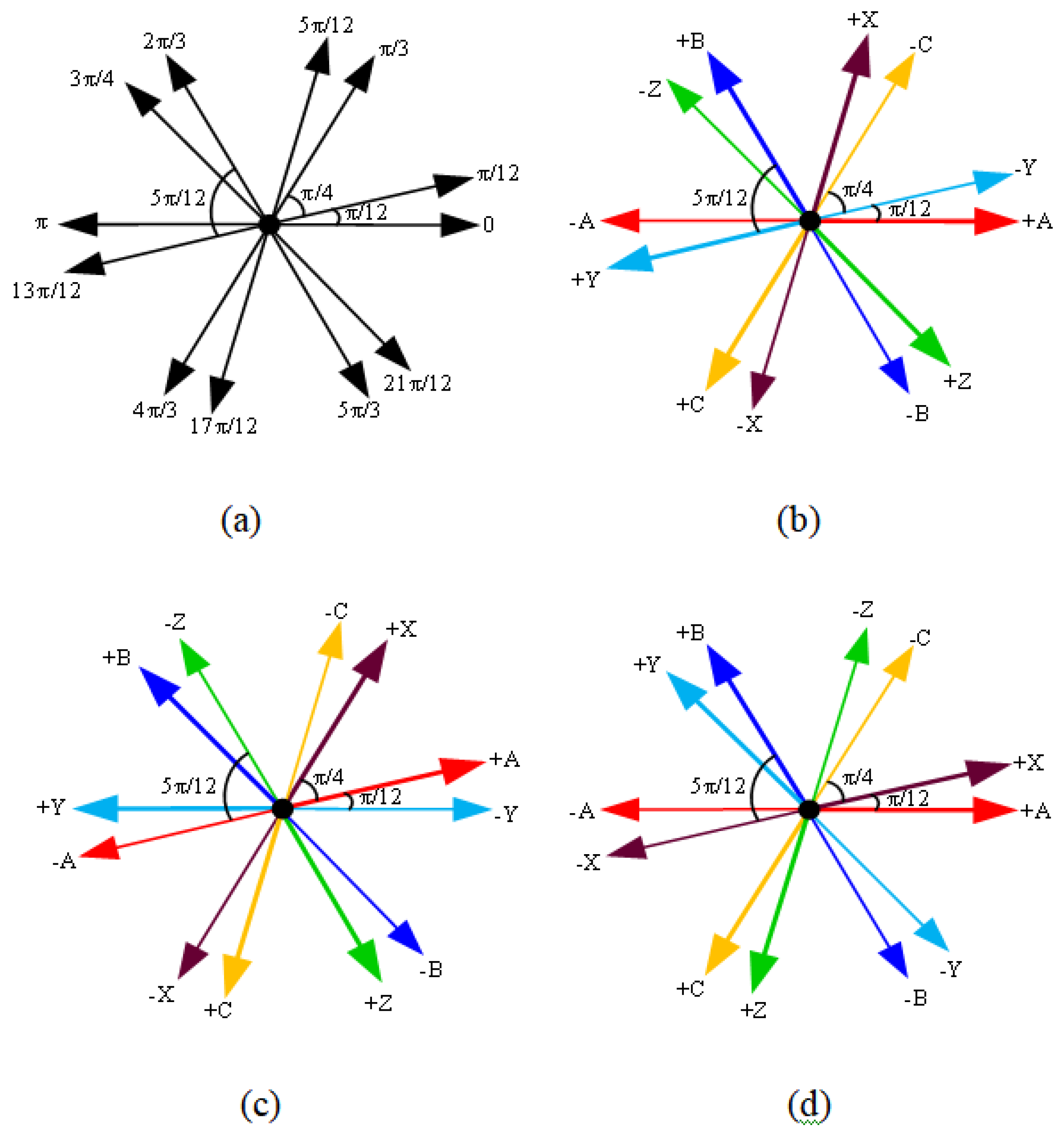
Phase Swapping (a) Winding Placement On The Stator (b) Model-I And (c) Model-III (d) Model-V.
Figure 5.
Phase Swapping (a) Winding Placement On The Stator (b) Model-I And (c) Model-III (d) Model-V.
4. Proposed Control Strategies
This section deals with the machine control strategies over its entire speed range that will be apply to control the operation of machine as shown in the Figure 6. The machine control over entire speed range involves dual inverter machine control. Therefore current controlled machine drive system is proposed instead of voltage control machine drive system to overcome any imbalance power sharing of the two inverter sections. Moreover, two control strategies over its entire speed range are proposed to operate the machine. One control strategy adopts minimum d-axis current control to operate the machine. Second, control strategy maximizes the speed range of the machine as much as possible by utilizing both flux weakening techniques together: the conventional one and the winding switching topology. A control approach projected that avoids the severe switching transients at winding switching instant. Furthermore, this switching control strategy utilizes current control in conjunction with the thyristors to avoid such unfavorable conditions during continuous operation of the machine.
4.1. Drive Configuration at Stage-I
The machine operation at stage-I is the basic 3 phase machine which is being controlled with a single inverter as shown in Figure 7. This stage represents a conventional machine and the operation of the machine in this stage is not a part of the uninterrupted process of proposed machine drive topology. This stage is included only to obtain the operation characteristics of the machine under conventional flux weakening technique. Conventional machine operation will be compare with it and the proposed machine design and drive topology.
4.2. Drive Configuration at Stage-II
At stage-II the machine configuration is converted into 6 phase machine by dividing winding of 3 phase machine into two equal sub windings which named are windings ABC and winding XYZ, and dual inverter topology is adopted to operate the machine. Therefore, net MMF of machine comes out to be the additive sum of MMF from two sub windings and is equal to the MMF of the 3 phase machine at stage-I. Circuit diagram to operate the machine at stage-II is shown in Figure 8. When the 3 phase machine is converted into 6 phase machine, number of turns of each phase reduces to one half of number of turns of the basic three phase machine. Therefore, V terminal of the 6 phase machine are lower than the Vt of 3 phase machine and results in voltage boost-I as described earlier. Voltage boost-I will enable the machine at stage-II to be operated beyond the rated speed of the machine at stage-I while maintaining the rated output torque. Therefore, the constant torque region will be extended due to voltage boost-I. Also the extended constant torque region will result in boost of machine output power beyond one p.u. Hence the machine operation in stage-II will have two benefits over basic three phase machine operation at stage-I:
1. Extended constant torque region.
2. Enhanced output power beyond one p.u.
The problem associated with dual inverter fed machine are the common mode voltages and the common mode circulating currents . Study in adopted separate Vdc for both inverters to avoid these problems. Owing to the problems in the above discussion, current controlled system will be adopted in the proposed control strategies instead of voltage controlled system to avoid any imbalance currents.Another important point is the selection of frame of reference for the implementation of the current regulators. It has demonstrated that the stationary frame PI regulator has steady state error for back EMF loads . Therefore, we need to model back EMF as disturbance or implement PR (proportional + resonant)regulator.
4.3. Drive Configuration at Stage-III
At stage-III, polarity of XYZ winding reversed to achieve field weakening effect as shown in the Figure 9. To achieve operating conditions of machine in Figure 9, the direction of the current in XYZ winding is reversed i.e. the currents are forced to enter at the non-dotted ends and leave at the dotted ends. This generates negative MMF from the machine winding XYZ while there is still a positive MMF from winding ABC because the current direction in ABC winding is not reversed. Hence, the MMF of the XYZ winding and ABC winding subtract each other resulting in an overall reduced MMF. The operation at stage-III as described above is realized using the drive circuit as Figure 10. When the machine operation is converted from stage-II operation in Figure 9. to the stage-III operation in Figure 10, the machine configuration changes from neutral connected machine to open winding machine. This transformation of the machine from star connection to open wining connection results in times higher terminal voltages. This is due tothe fact that the inverter has to overcome line voltages in order to inject current in star connected machine whereas it needs to overcome phase voltages to inject current in open winding configuration. Therefore, inverter faces times lower machine terminal voltages in open winding configuration compared to neutral connected machine. In other words, times higher voltages are available at inverter side to inject currents into the machine winding at this stage. These, times higher voltages were termed as voltage boost-II in the previous chapters and enable the machine to operate with constant torque region at stage-III operation by times the FW speed where FW speed can be defined as fw times the rated speed and will be abbreviated as Nfw. Another parameter that is relevant to Nfw and will be utilized in proposed control strategy-II is the winding switching speed of the machine (Nws). Nws is defined to be the speed of the machine at the winding switching instant. For control strategy-I Nfw is essentially the same as Nws.
5. Overall Drive Circuit
Overall machine drive system contains of two control loops;outer speed and inner current control loop. PI (proportional +integral) controllers are used to implement the speed control loop and the current control loop. Output of the speed control loop is used to generate the reference current signal for the current regulators. Six PI controllers are used to control two dq0 current components from two sub windings ABC and XYZ. Standard transformations are used to transform the three phase currents Iabc and Ixyz measured at the motor terminal into two phase components (I0) in the stationary frame of reference. Over all circuit diagram is mentioned as Figure 10.
These currents are now altered into Idq01 and Idq02 using above equations. is different for the different machine models at stage-II operation but is 180ofor all machine models at stage-III operation .
These currents Idq01 and Idq02 are compared with Idq01* & Idq02*. Output of PI controllers Icdqo1 & Icdq02 is again transformed back to Iabc & Ixyz using the above equation.
6. Machine Modeling in SIMULINK
Before proceeding towards the proposed control strategies machine, it is necessary to develop SIMULINK model of proposed machine designs so that the proposed control technique could be verified using simulations. Electrical subsystem deals with electrical energy related to the machine like current, voltage, inductance, resistance and the back EMF whereas the mechanical subsystem deals with the mechanical energies of the machine like mechanical speed, torque, friction and the inertia.
6.1. Electrical Subsystem
Electrical subsystem of the machine in its simplified form can be represented as and is rewritten here for reference. Resistive voltage drop can be modeled using gain block available in the SIMULINK with gain parameter set to the winding current.
Whereas the inductive voltage drop can be modeled as a constant block for inductance and a derivative block for the currents of the machine. Inductance equation for any phase of the machine for the six phase machine case is given as
Where Ls is inductance of phase A due to phase A itself and its mutual component due the excitation of all other phases. Fortunately, there is a mutual inductance block available in the SIMULINK that can model the inductance and resistance of the machine using resistance and inductance matrices. The back EMF can be modeled as controllable voltage source whose voltage is controlled by the flux linkage and speed as shown in the Figure 11.
6.2. Mechanical Subsystem
Mechanical torque of the machine can be represented as
Where Te is the electrical torque, Tm is the mechanical torque, J: inertia, F : friction constant and TF: static shaft torque. Equation. 9. can be transformed into the SIMULINK model as shown in Figure 12.
6.3. Proposed Control Strategy-I
The main benefit of FW by of winding switching technique is that it does not require negative d-axis current. However, when winding is switched from stage-II to stage-III, flux reduces abruptly by an amount determined by the displacement angle b/w two sub winding’s. Hence, an abrupt torque acceptable for certain applications. Moreover, output power of the machine at winding switching can go below one p.u value resulting in an undesirable operation. Hence, it is essential to operate the machine in such a way that it meet the load requirements over its entire speed range. This phenomenon is termed as voltage boost-II in this research.
Currents are maintained within the rated current limits according to above equation over its entire speed range
Where I: rated machine current for 3 phase machine operation
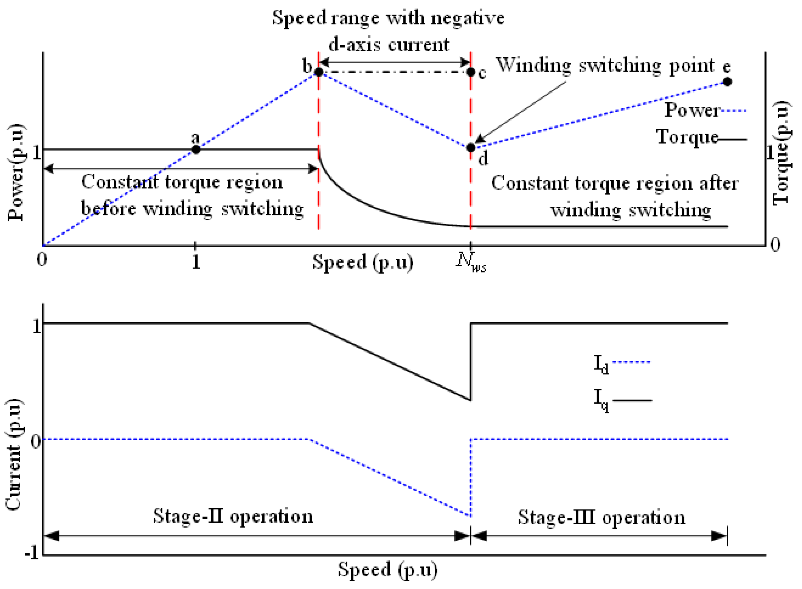
6.4. Principle of Operation
Figure 13 demonstrates the control strategy of current for proposed design. The machine is started with Id , which is equal to zero, control until it will approach the speed which will be rated as shown in the Figure 13. The speed will be continuously increasing with constant torque until it will reach at point ‘b’ due to voltage boost-I. Machine parameters effect the operation of machine. voltage boost-I used to achieve the winding switching speed so if it is achieved by this method then there will be no need to apply negative-d axis current. In this event, point ‘b’ occurs at Nws. If speed is not achieved by voltage boost-I then negative d-axis current must be applied to achieve required speed further from point ‘b’ to ‘d’. By definition, this increase in speed using a negative d-axis current depends upon the relative size of E versus Xd-Id. Here main point is that power of machine will remains constant irrespective of speed change between points.
Figure 13.
Simulink Machine Model Mechanical Subsystem.
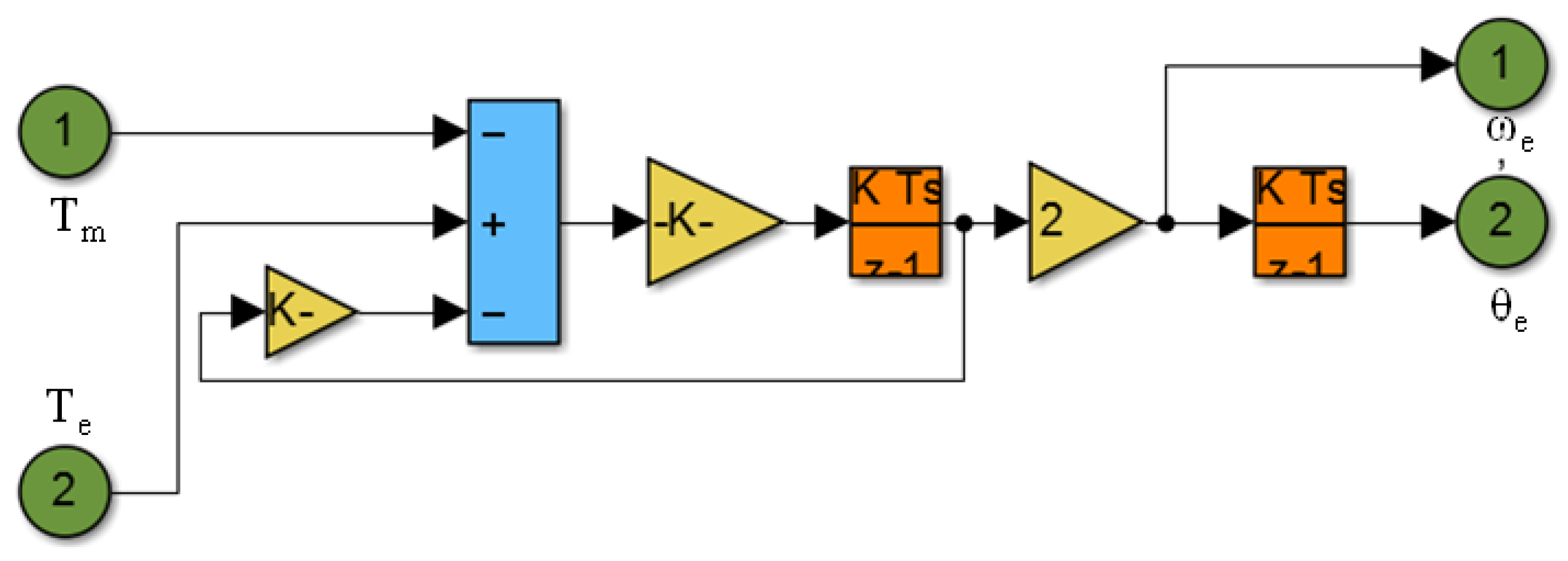
Figure 14.
Proposed Control Strategy-I.
6.5. Proposed Control Strategy-II
Strategy-I presented minimum d-axis current control and do not utilizes the negative d-axis current to maximize the speed. Moreover, according to proposed control strategy-I, the machine should have inherent capability to extend its speed until winding switching point. However, all applications do not require these conditions. Therefore, control strategy-II is proposed to cope with these issues and maximize the speed as much as possible.
6.6. Principle of Operation
Machine operation divided total our regions of operation in which two regions will be at stage-II and other two at stage–III . V terminal is considered as rated voltage that is being supplied by inverter. Basic 3 phase machine converted into 6 phase so phase back EMF reduces and extra V terminal is available for injecting rated current. Hence, there will, be extended region of constant torque and increases the maximum power capability due to its ability to operate beyond the rated speed. This constitutes region-I operation with Id=0 control, When extended torque region limit achieved, negative d-axis current applied for further increase the speed as mentioned by Region-II. Necessary condition for the proposed control strategy-II is that windings of the machine are switched at a torque of /fw to avoid torque transient at winding switching. Therefore, to increase the speed, negative d axis current applied in region-II until torque decreases by /fw. This ends the region-II operation and also stage-II operation of the machine comes to an end. Negative d axis current removed and winding switched to operate the machine with unity Pf. Machine maintains at least one p.u power over its entire speed range: After windings switching, machine operation is converted into stage-III operation and machine is controlled in an open winding configuration. Hence, voltages that are times higher are available to further speed up the machine after winding switching (voltage boost-II). The machine will again operate in the constant torque region due to the times higher voltage, up to a speed of , as indicated by region-III . Therefore power of the machine will again increase beyond one p.u due to its high speed operation with constant torque in region-III. When the machine is reached at its maximum speed limit due to times higher voltage, a negative d-axis current is again applied in region-IV to further speed up the machine for its final speed operation. The final achievable speed of the machine is dependent upon three factors: flux weakening of the machine upon winding switching, voltage boost-II and finally the machine inherent capability to extend its speed using negative d-axis as shown in the Figure 15.
7. Simulation Results and Discussion
7.1. Simulation Results of Machine Design – I
A simulation model for proposed machine design-I is established in Maxwell 2-D software for the finite element analysis (FEM) of the machine. Machine parameters are being mentioned in the simulation of this machine is performed at base speed of 900 rpm and back EMF is measured for all three stages of machine. Back EMF was measured to be 59.90 Vrms at stage-I and 34.85 Vrms at stage-III. The ratio of the simulated back EMF at stage-I to stage-III is found to be 1.72 that validates the theoretical calculation of 1.73. Torque was found to be 7.01 Nm in at stage-I and 4.05 Nm at stage- III. The ratio of the torque at stage-I to stage-III is found to be 1.73 that validates the analytically calculated values. Figure 16(b) shows the simulated torque profile of proposed machine design-I.
7.2. Simulation Results of Machine-II
A simulation model for the proposed machine design-II is developed for its FEM analysis to validate the analytical analysis. Dimensions of machine design-II are exactly same with the machine design-I except the number of rotor poles that are two in this case and the winding configuration is changed to accommodate the proposed machine design windings. All machine models are simulated for a rated speed of 500 rpm and a rated torque of 5.19 Nm. Rated speed and rated torque are selected, keeping in mind the mechanical integrity of machine while operating at high speed. FEM simulation results for the no load case for model-III are depicted in Figure 17 for all three stages of operation. Multiple flux weakening ranges of the machine design-II under phase swapping method are depicted that are achieved without any hardware change of the machine. All the machine models are also simulated for the rated conditions of the speed and the torque. Table 1 represents the overall summary of the simulation results for the proposed machine design-II. Lead angle and the lag angle information in the 5th and 6th columns of the Table 1 are important to implement the machine drive system. The torque to-current ratios for the five models are depicted in Figure 18. It shows that the torque-per-ampere ratio of the six-phase machine configuration is the same for all five machine models. The torque per ampere ratio increases for the basic three-phase machine model in stage I as the angle of the two sub-winding between decreases. Moreover, the torque per ampere ratio for stage-III operation reduces as angle between two sub-winding decreases as shown in the Figure 19. The main reason is that when angle decreases, FW increases, and hence, more current is required to produce torque with reduced flux of machine.
7.3. Simulation Results of Proposed Control Strategy – I
The inductance matrix for the 6 phase machine configuration of the proposed machine design-I obtained from Maxwell 2-D simulations is given as The proposed control strategy-I is verified using the proposed machine design-I.
The chosen speed is 900 rpm with 7.01 Nm torque. These operating parameters are selected according to the mechanical integrity of the experiment machine to operate at high speed and current limits of machine winding. The simulation results for the proposed control strategy-I are shown in Figure 20(a–c). As described earlier, when the 3 phase machine in stage-I is converted into the 6 phase machine at stage-II, back EMF reduces to one half in the six-phase configuration. The machine should achieve a speed of 1.73 times the rated speed while maintaining the rated torque by the virtue of the extra terminal voltages available when it is converted from stage-I to stage-II. However, the flux of the machine reduces by 1.73 times when machine is converted from stage-II to stage-III by winding switching, Therefore, if it is allowed to speed up the machine with rated torque until 1.73 times the rated speed at stage-II, there will be a torque transient (torque will reduce from 7.01 Nm to 4.05 Nm) at this point when the machine operation will be converted from stage-II to stage-III. This torque transient is not desirable at this point. Therefore, the torque of the machine is intentionally reduced from 7.01 Nm to 4.05 Nm smoothly from 1350 rpm to 1557 rpm by reducing Iq of the machine in Figure 20(a) and (b). When the windings are switched at 1557 rpm (1.73 p.u), there is no torque transient because machine is already operating at 1.73 time lower torque compared to the rated torque. However, a momentary torque transient occurs at this point due to winding switching as is obvious from Figure 20(c). Machine operation is converted into open winding configuration at this point and time higher terminal voltages (voltage boost-II) are available that further extends the speed by 1.73 time the winding switching point speed (1557 rpm) and hence a final speed of 2690 rpm is achieved. It is also evident from the results that the machine is operating with rated currents and rated torque before the currents are intentionally reduced to achieve the one p.u power condition at winding switching point i.e. 1.73 times the rated speed and 1/1.73 times the rated torque. Just after winding switching, flu is reduced by 1/7.3 times; hence, machine can generate 1/1.73 times the rated torque with the rated currents as is evident from Figure 20(c). Also, it can be noted that the d-axis current value is always zero over the entire speed rage of the machine in this case because the machine achieved the winding switching point without applying a negative d-axis current.
7.4. Simulation Results of Proposed Control Strategy – II
The proposed machine design-II used to authenticate the proposed control strategy-II. The machine base speed is rated 500 rpm with a rated torque of 5.19 Nm. The drive system for the proposed control strategy-II is implemented in SIMULINK. The simulation results for the proposed control strategy-II using the proposed machine design-II are shown in Figure 21(a–e).
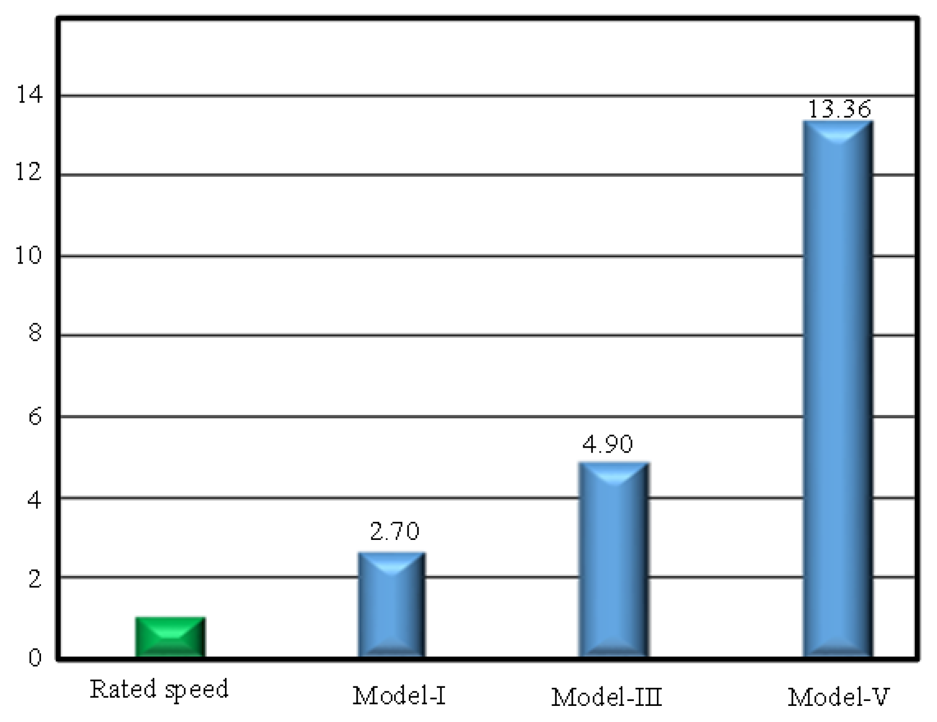
The four regions of operation and the winding switching transients are clearly demonstrated in these results. Moreover, it can be observed that when the machine windings are switched while driving the machine from region- II towards region-III, negative d-axis current is removed and the machine operation reverts back to the unity internal power factor. Furthermore, the conditions for at least one power per unit throughout the speed range of the five machine models under control strategy-II are clear from these figures. Machine models, model-I, model-II and model-III can maintain at least one p.u power because the values of Nfw are smaller compared to values of Nws in these cases as shown in the Figure 22. However, machine model-IV and model-V cannot maintain at least one p.u because Nfw in these cases is larger compared to Nws. The power of the machine drops below one p.u. and the machine continues its operation with constant torque until its speed reaches Nfw speed and the machine achieves a p.u. power again. Maximum achievable speed design-II under phase swapping method using control strategy-II . It is obvious that same machine design without changing any hardware of the machine can achieve three different speed ranges. Also the maximum speed range achieved under the proposed phase swapping method is more than thirteen times the rated speed of the machine that is very wide speed range. Hence, any applications requiring speed range up to thirteen times the rated speed of the machine can benefit from the proposed concept. The proposed NSPMM models that can employ the winding switching topology for flux weakening operation. System analysis is presented for the machine states at stage-I, stag-II and stage-III. Two novel concepts of coil displacement and phase swapping are introduced to achieve multiple wide speed range operations of the machine from same machine model. Coil displacement method requires physical displacement of the winding coils on the stator periphery to achieve multiple high speed operations. Contrary, phase swapping method do not require any hardware change in the structure of the machine. However, coil displacement method provides more flexibility in achieving multiple speed ranges of the machine compared to phase swapping method. Maxwell 2-D simulation outcomes are accessible to authenticate the proposed machine designs.
Figure 22.
Simulation results for proposed control strategy-II (a) model-I (b) model-II (c) mode-III (d) mode-IV (e) model-V.
Figure 22.
Simulation results for proposed control strategy-II (a) model-I (b) model-II (c) mode-III (d) mode-IV (e) model-V.
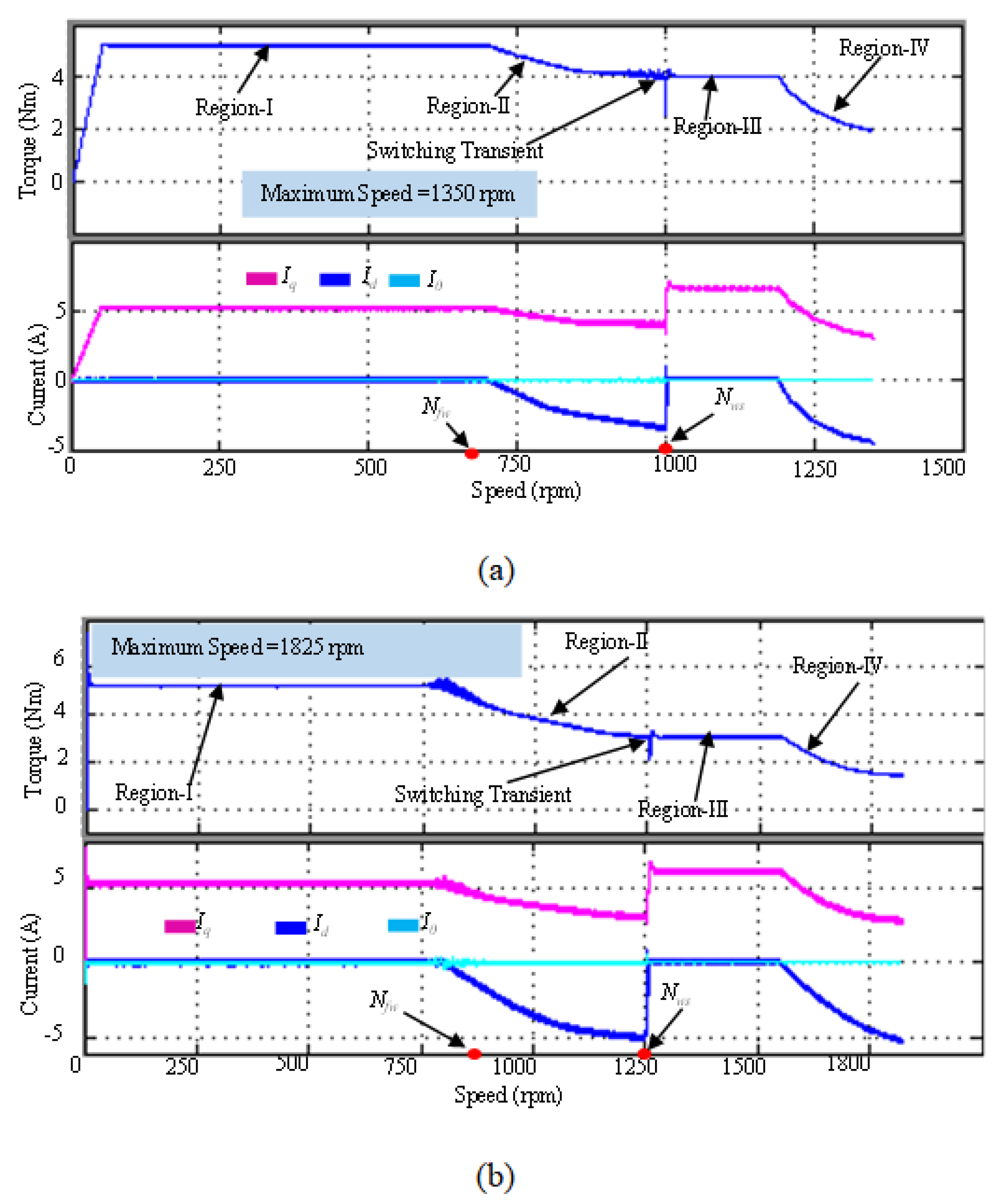
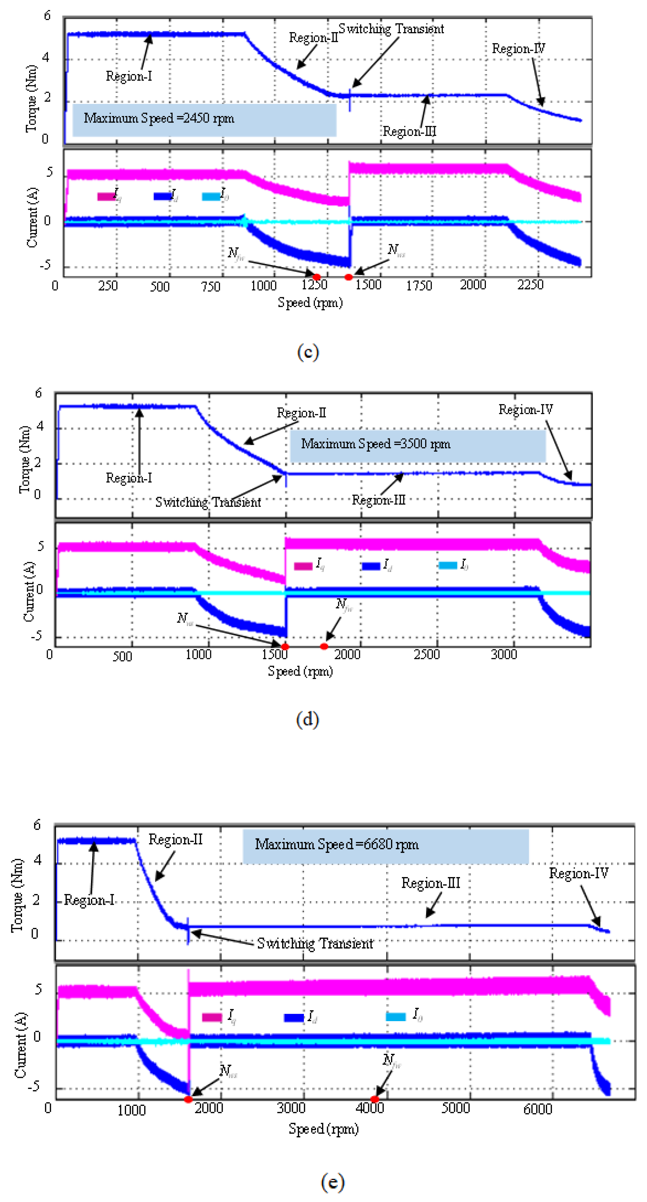
Figure 23.
Simulated Maximum Achievable Speed of The Machine Models Under Phase Swapping Method.
8. Conclusions
The main objective of research work is to associate high-speed operation to non-salient PM machines that are inherently considered to be the poor candidates for this purpose. Low-permeability surface mounted permanent magnets associate low inductance characteristics to these machines. FW capability of the PM machines, on the other hand, is related to their d-axis inductance, and normally a large value of this inductance is required for their high FW capability. Hence, NSPMM are not considered a favorite choice for applications requiring high degree of FW. The winding switching technique can effectively solve this problem and FW can be attained without depending on the d-axis inductance. However, the winding switching technique requires a certain slot per pole per phase combination that results in a certain electrical angle between the stator slots. The angle between the stator slots plays an important rule in determining the flux weakening capability using winding switching. The displacement angle between two slots and the number of slots displaced between two sub-windings determine the final FW capability. This fact is utilized in proposed wide speed range operations methods of coil displacement and the phase swapping. These two proposed concepts associated wide speed range operations to a single machine that can be used in any application requiring any flux weakening range with certain limits. Control strategies have been proposed to achieve continuous operation over its entire speed range. Control strategy I utilized a minimum negative d-axis current and hence reduced the risk of irreversible demagnetization of the surface-mounted permanent magnets. However, control strategy II utilized FW using negative d-axis current and FW using the winding switching technique to enlarge the maximum speed range operation of the machine. Both control strategies extended the constant torque region of the machine by utilizing the benefits of dual-inverter-fed machine and the open winding configuration operation. This extension in the constant torque region also resulted in a boost in the maximum power capacity of the machine.
Replication of results:
All the details necessary to replicate the results are presented in the manuscript.
Further implementation code and numerical data can be shared by contacting the authors.
Author Contributions
Aamir Farooq: Methodology, Writing—Original Draft; Investigation, Validation; Muhammad Shahzad: Conceptualization, Writing—Review & Editing.
Funding
This Research work is supported by King Saud University Saudi Arabia, Under the grand number RSPD2024R553.
Institutional Review Board Statement
Manuscript does not report on or involve any animals, humans, human data, and human tissue or plants.
Data Availability Statement
Further implementation code and numerical data can be shared by contacting the authors.
Conflicts of Interest
The authors declare that they have no known competing financial interests or personal Relationships that could have appeared to influence the work reported in this paper.
Abbreviations
LIST OF ABBREVIATIONS
| NSPMM | Non-salient PM Motor |
| FEM | Finite Element Analysis |
| Xs | Per unit value of the synchronous reactance |
| V | Terminal voltage of the machine |
| E | Phase-back EMF of the machine |
| I | Phase current |
| R | Phase resistance |
| L | Phase inductance |
| Lax | Mutual inductance of phase A and phase X |
| Ls | Inductance of phase A due to energizing of all phases |
| Ecum | Net back EMF of the machine in cumulative mode |
| J | Moment of Inertia |
| Tm | Mechanical output torque |
| Te | Electrical torque generated |
| F | Frictional force |
| TF | Static shaft torque |
| P | Mechanical output power |
| CRVI | Current regulated voltage source inverter |
References
- Shinde, S.K.; Waghmare, A.W.; Gupta, R.K. Enhanced control techniques for wide-speed operation of non-salient permanent magnet motors. Electric Power Systems Research 2022, 197, 107–115. [Google Scholar]
- O’Brien, J.P.; Kristiansen, A.D.; Ahmed, M.K. Wide-speed and torque control of interior permanent magnet motors using a robust model predictive control approach. IEEE Transactions on Industrial Electronics 2022, 69, 11545–11553. [Google Scholar]
- Chen, R.J.; Chen, W. Optimization of control strategies for non-salient permanent magnet motors in wide-speed applications. Journal of Electrical Engineering & Technology 2022, 17, 1315–1328. [Google Scholar]
- Bahrami, M.I.; Fazli, F.S.; Sadeghi, M.R.J. High-speed performance of non-salient permanent magnet motors with advanced rotor designs. Energy Reports 2022, 8, 109–118. [Google Scholar]
- Hossain, A.S.; Islam, M.R.; Hossain, K.A. Modeling and control of non-salient permanent magnet motors for wide-speed operations. Journal of Electrical Engineering and Automation 2021, 3, 254–261. [Google Scholar]
- Huang, S.; Wang, Y.; Hu, H. Optimization of Control Strategies for Non-Salient Permanent Magnet Motors for Wide Speed Range Applications. IEEE Transactions on Industrial Electronics 2023, 70, 4971–4980. [Google Scholar]
- Lee, J.; Kim, H.; Park, S. Enhanced Performance of Non-Salient Permanent Magnet Motors Through Advanced PWM Techniques. Journal of Electric Power Applications 2023, 15, 220–233. [Google Scholar]
- Zhang, L.; Liu, X.; Zhao, D. Field-Oriented Control for Non-Salient Permanent Magnet Motors: Achieving High Efficiency Across Wide Speed Ranges. Energy Reports 2023, 9, 2050–2059. [Google Scholar]
- Gonzalez, J.; Torres, A. Non-Salient Permanent Magnet Motor Drives: A Comprehensive Review on Speed Control Methods. Journal of Power Electronics 2023, 22, 1–20. [Google Scholar]
- Martinez, F.; Rodriguez, C. Mathematical Modeling and Control Strategies for Non-Salient Permanent Magnet Motors Operating at High Speeds. International Journal of Electrical Engineering Education 2023, 60, 343–358. [Google Scholar]
Figure 1.
Research Overview.
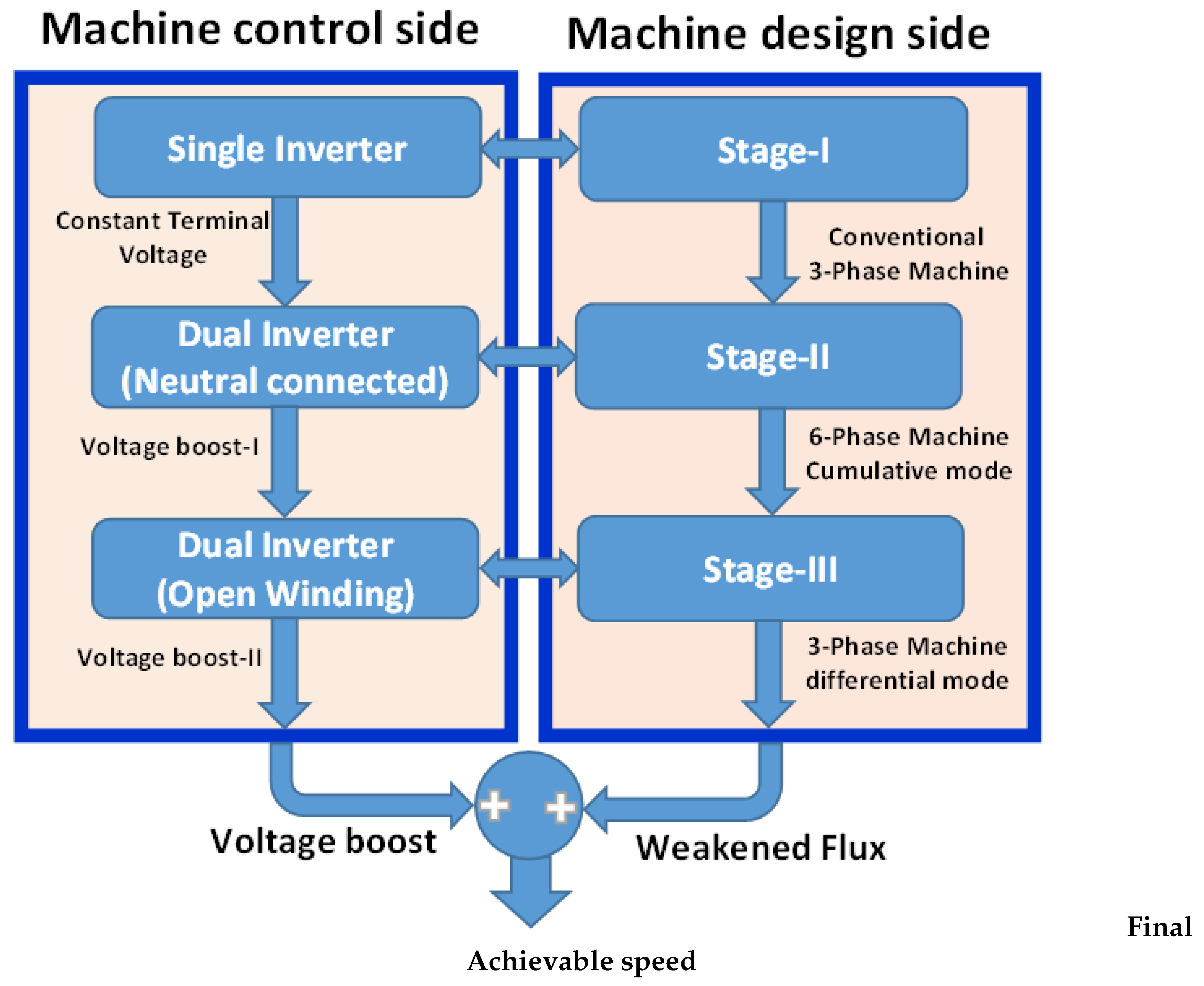
Figure 2.
Overview of the Proposed Machine Designs.
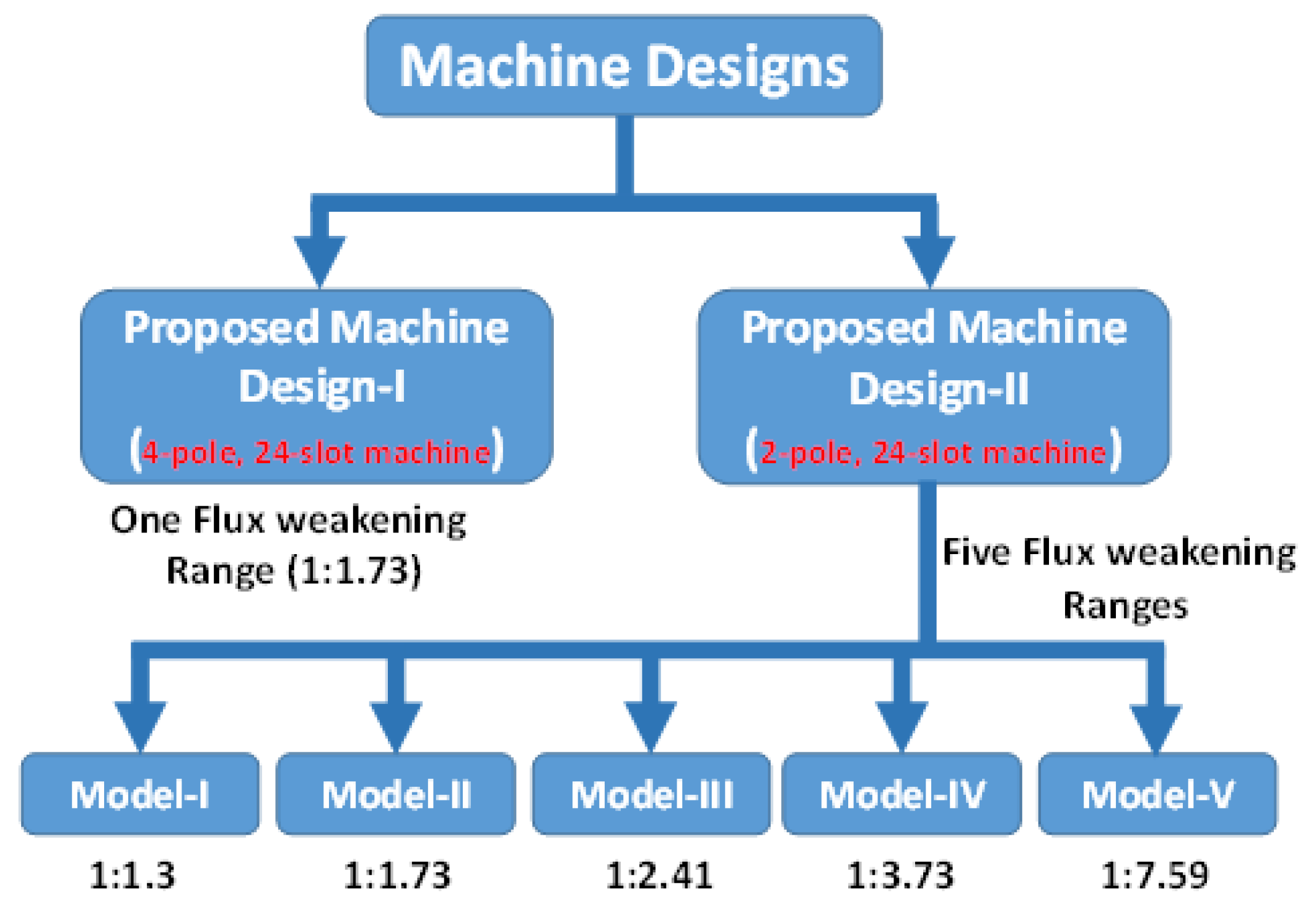
Figure 3.
Winding Configuration of the Proposed Machine Design-I (a) Stage-I (b) Stage-II and (c) Stage-III[6].
Figure 3.
Winding Configuration of the Proposed Machine Design-I (a) Stage-I (b) Stage-II and (c) Stage-III[6].
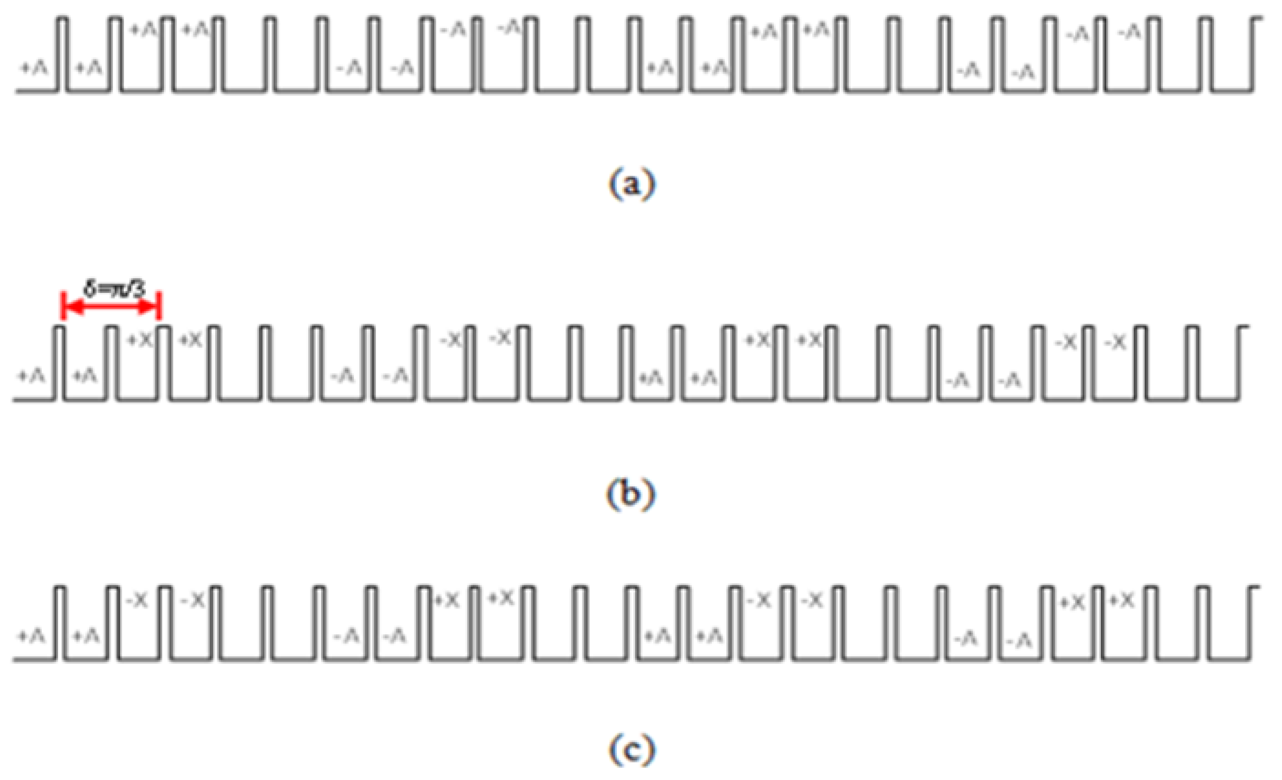
Figure 6.
Overview of the Proposed Control Strategies.
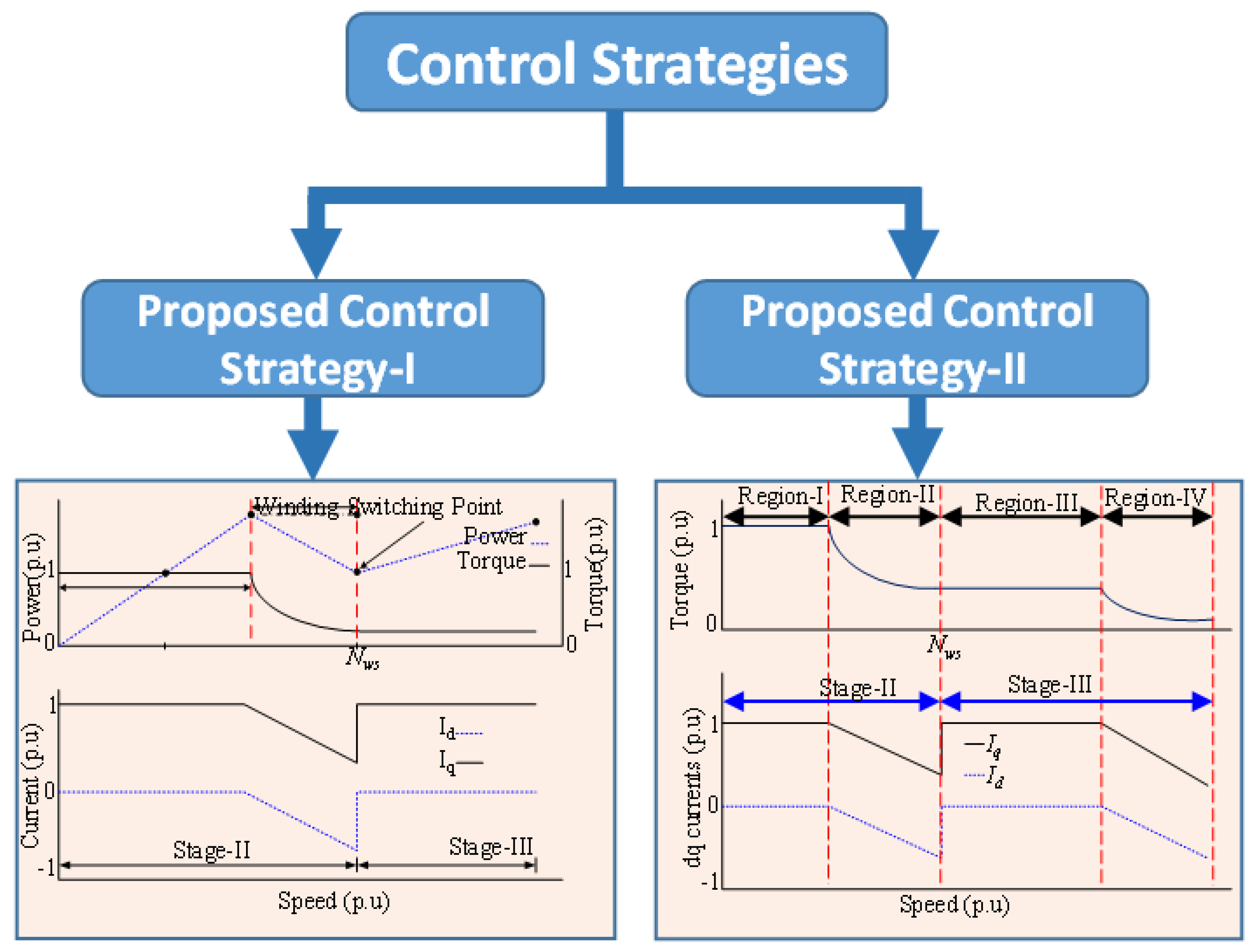
Figure 7.
Drive Circuit for Stage-I Operation.
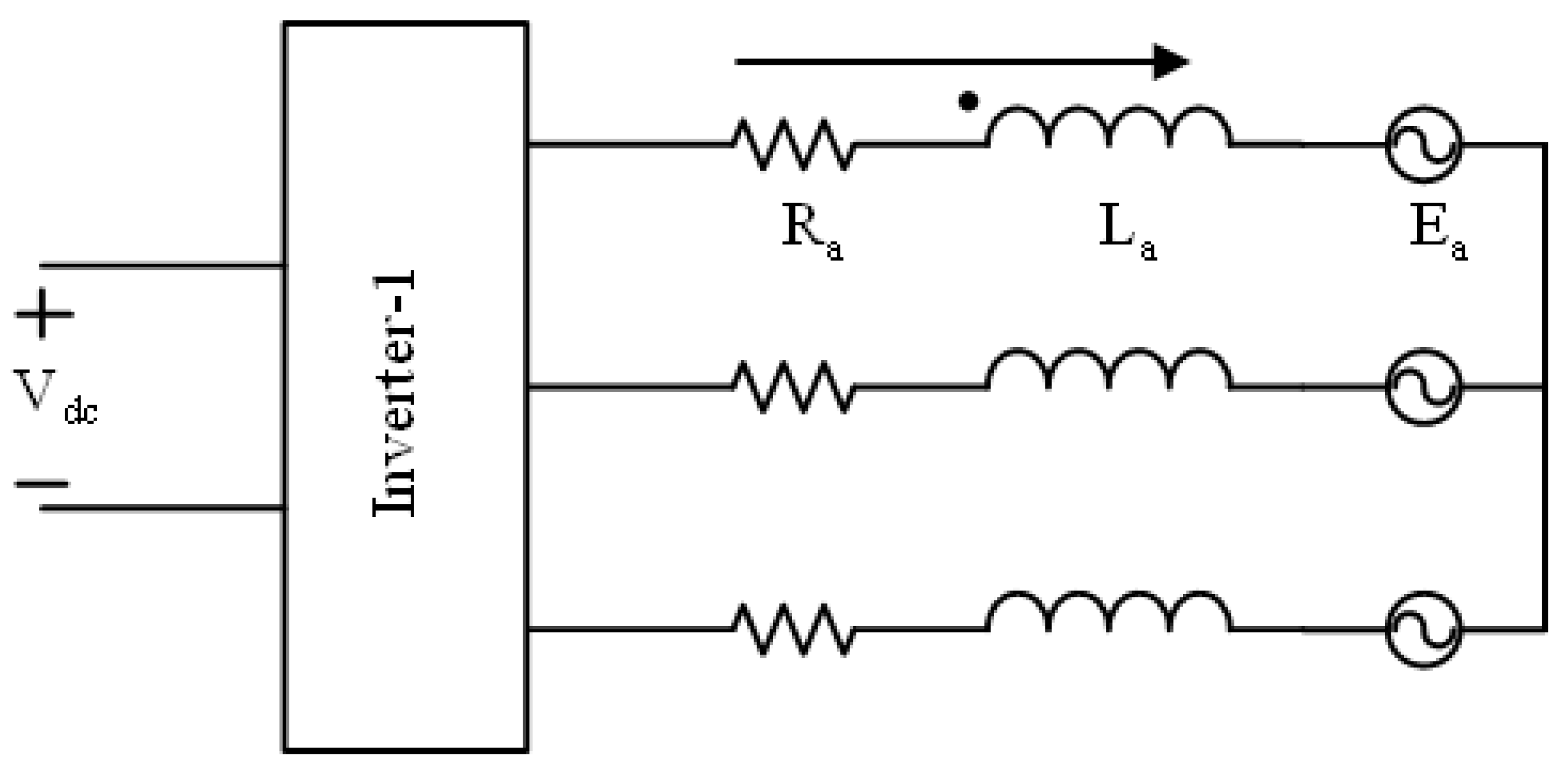
Figure 8.
Drive Circuit for Stage-II Operation.
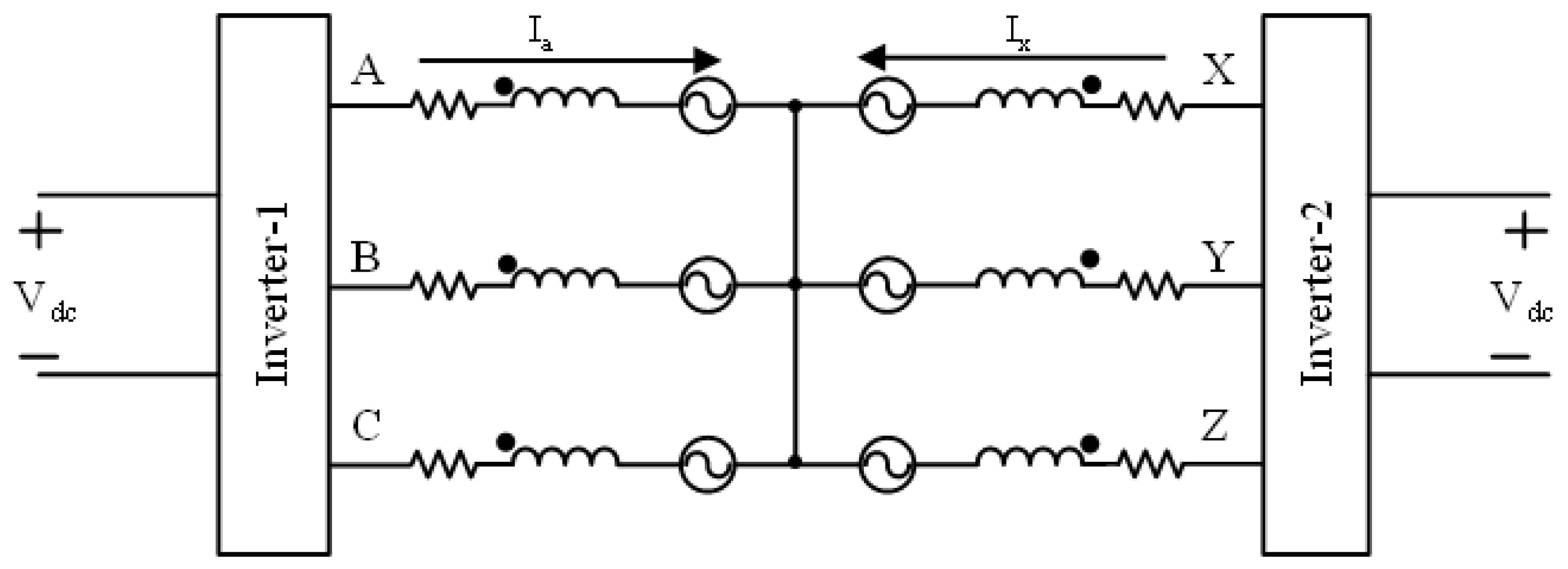
Figure 9.
Drive Circuit for Stage-III Operation.
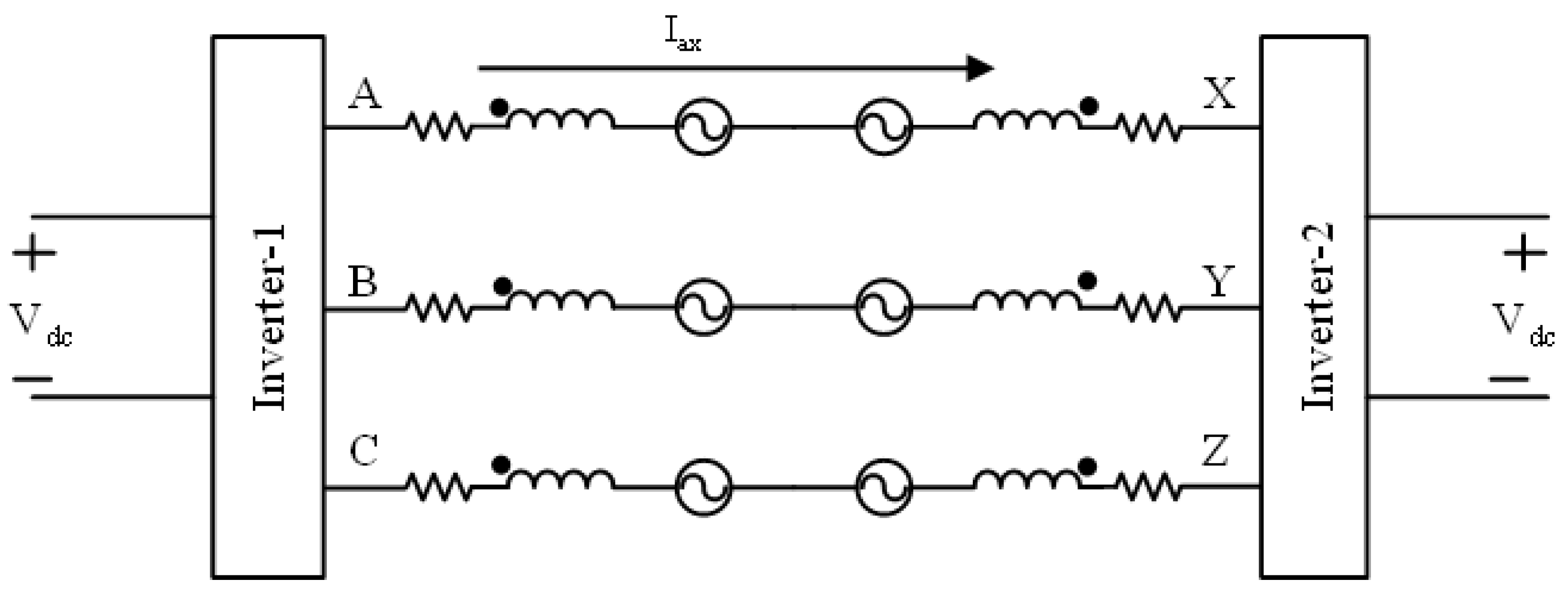
Figure 10.
Drive Circuit of the Machine for Electronic Winding Switching.
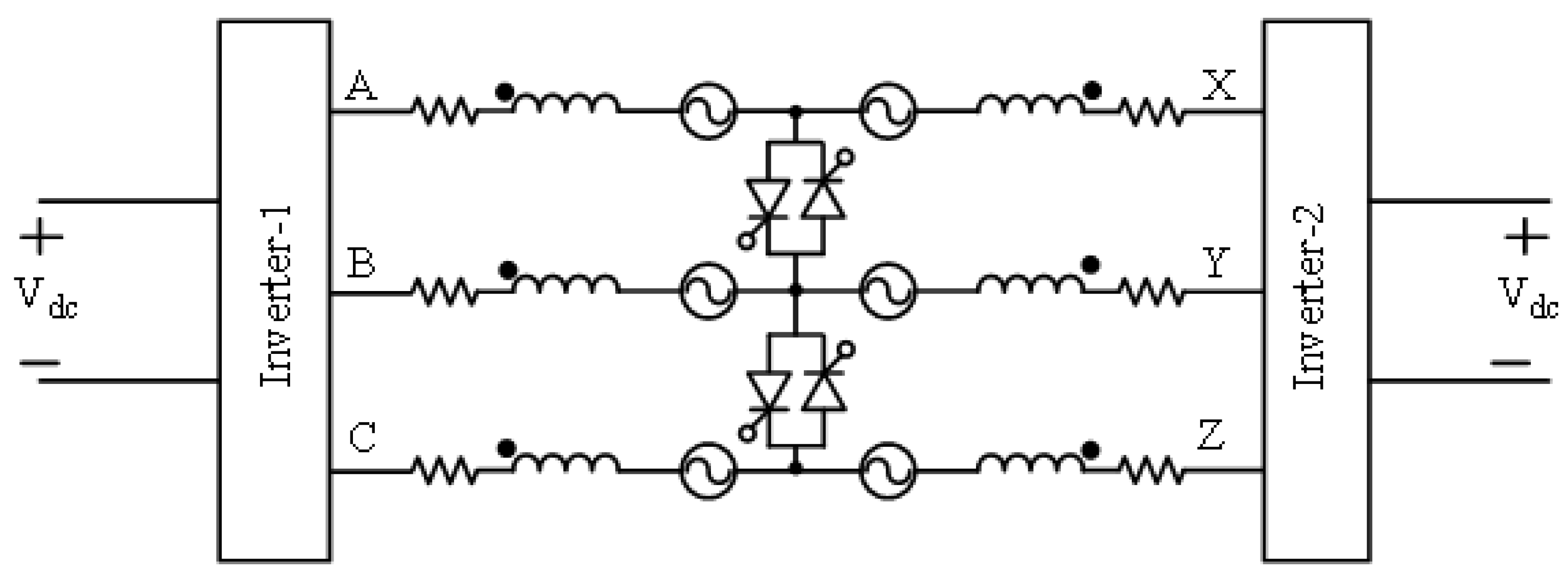
Figure 11.
Overall Control System.
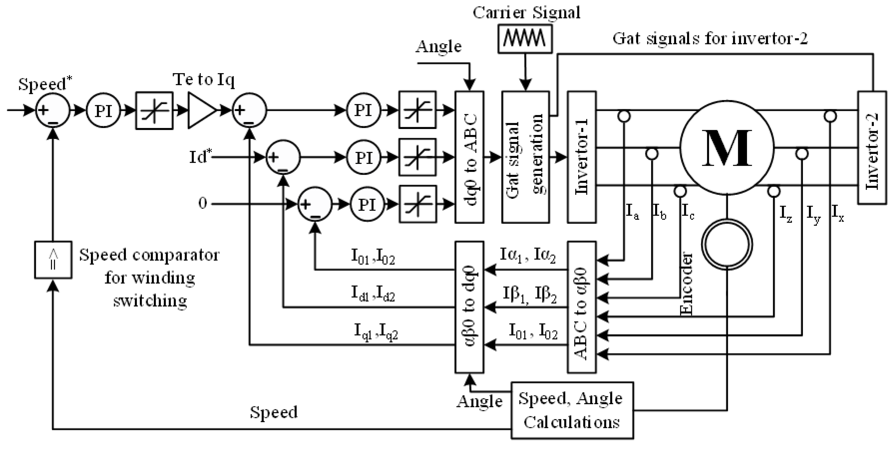
Figure 12.
Simulink Machine Model Electrical Subsystem.
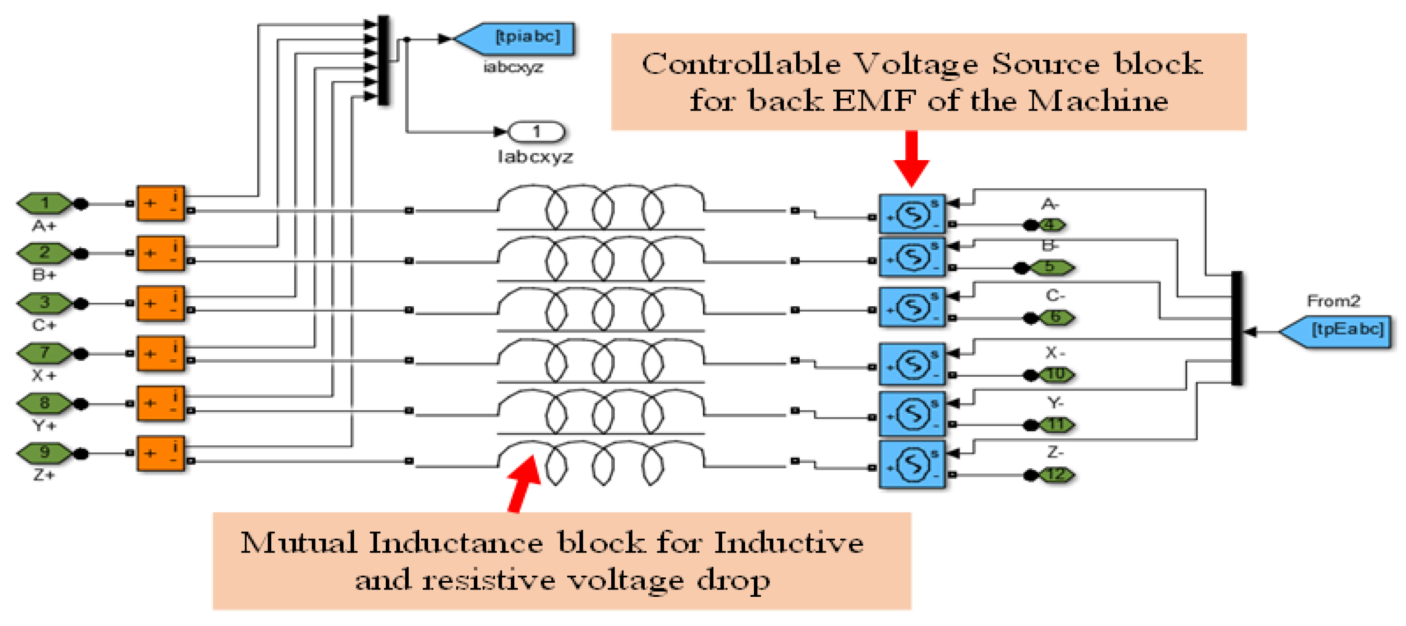
Figure 15.
Proposed Control Strategy-II.
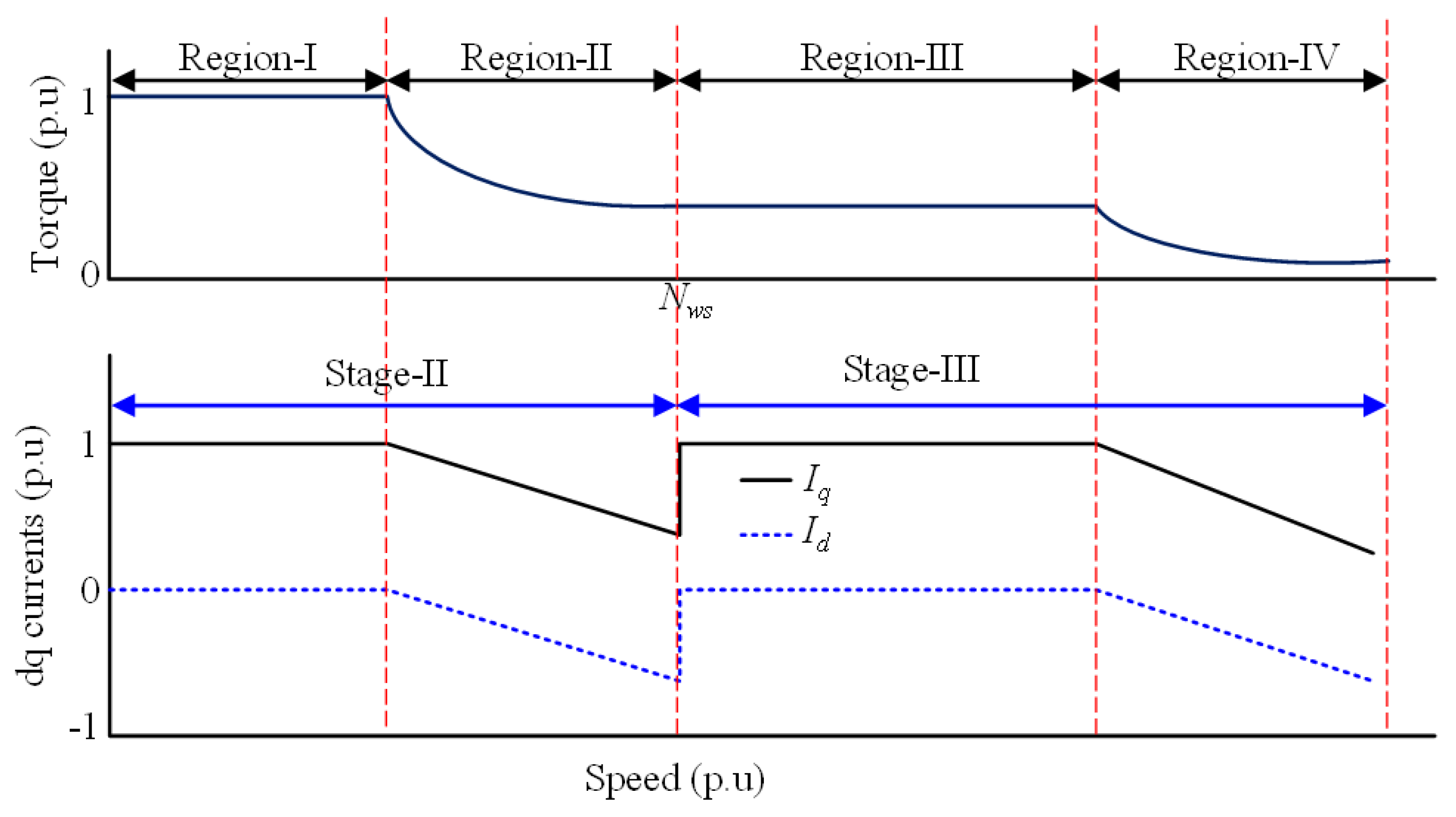
Figure 16.
Simulation model for proposed machine design-1 (a) basis 3 phase machine and (b) 6 phase machine after dividing the machine windings.
Figure 16.
Simulation model for proposed machine design-1 (a) basis 3 phase machine and (b) 6 phase machine after dividing the machine windings.
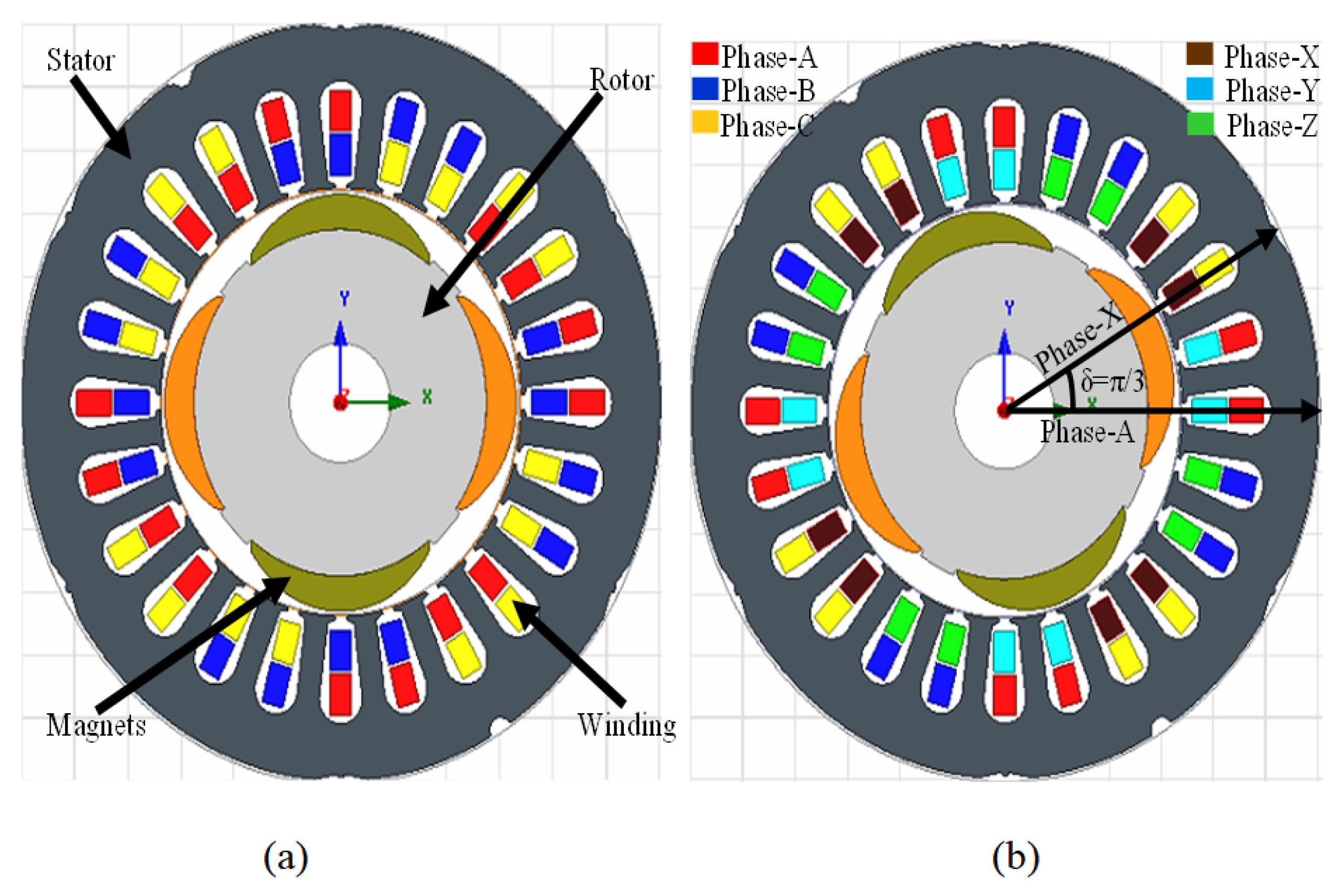
Figure 17.
Simulation results (a) back EMF profile and (b) torque profile.
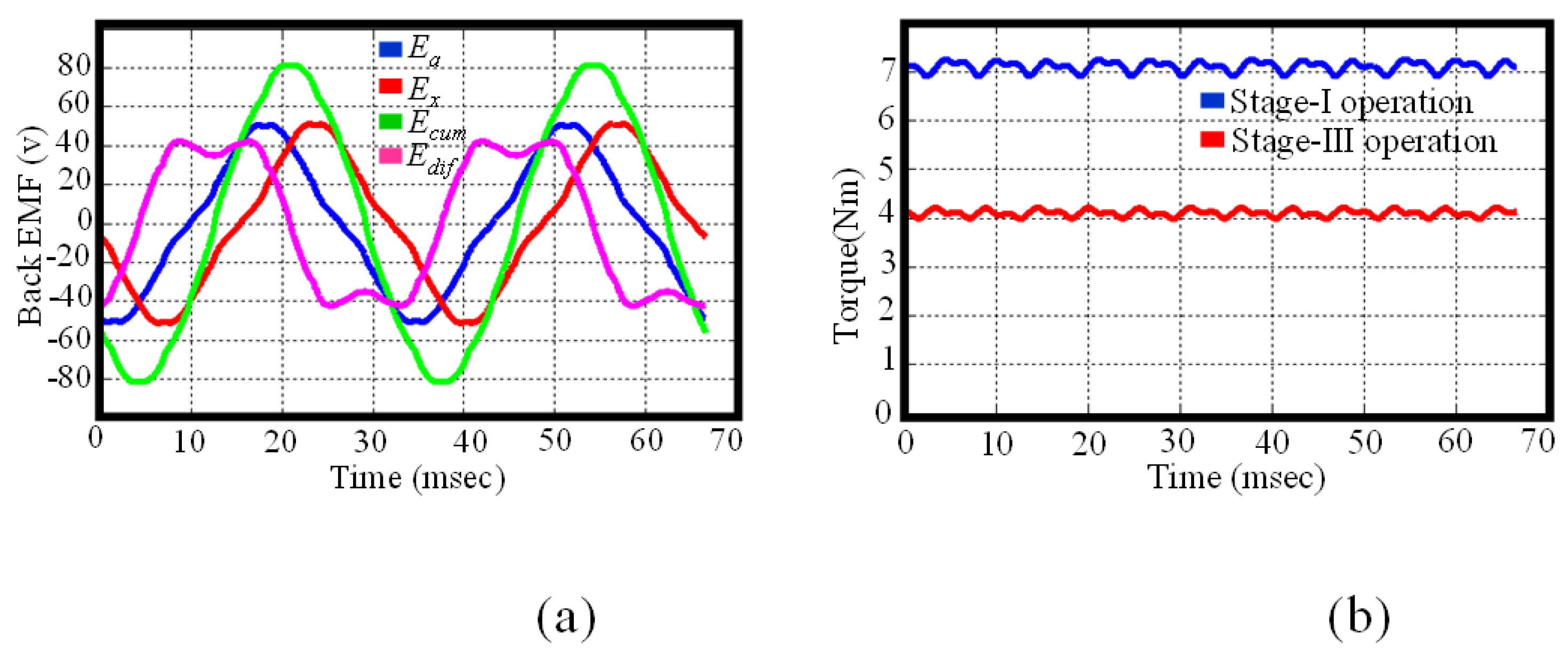
Figure 18.
Back EMF Profile of Model-III.
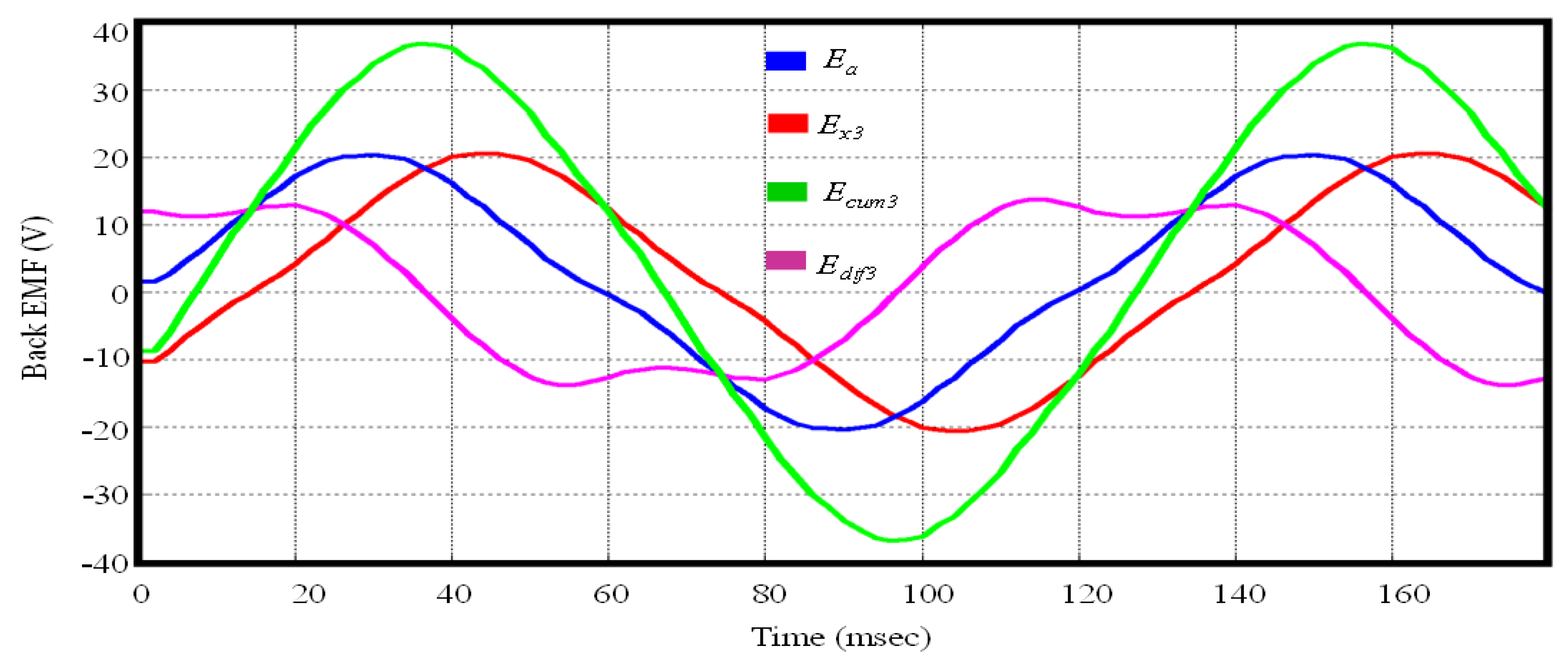
Figure 19.
Multiple flux weakening ranges of the machine design-II using phase swapping.
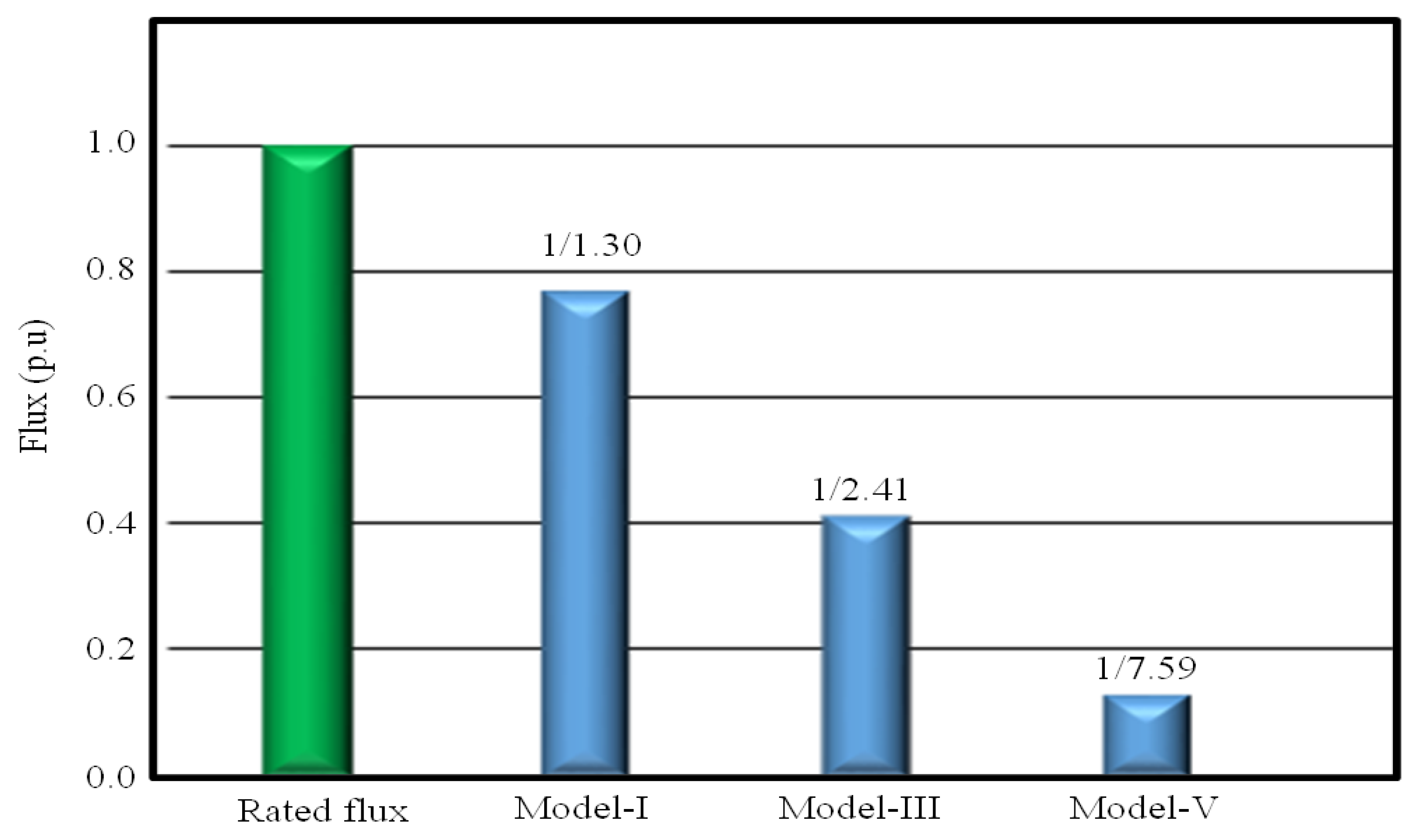
Figure 20.
Torque per ampere ratio of five models of the proposed machine design-II.
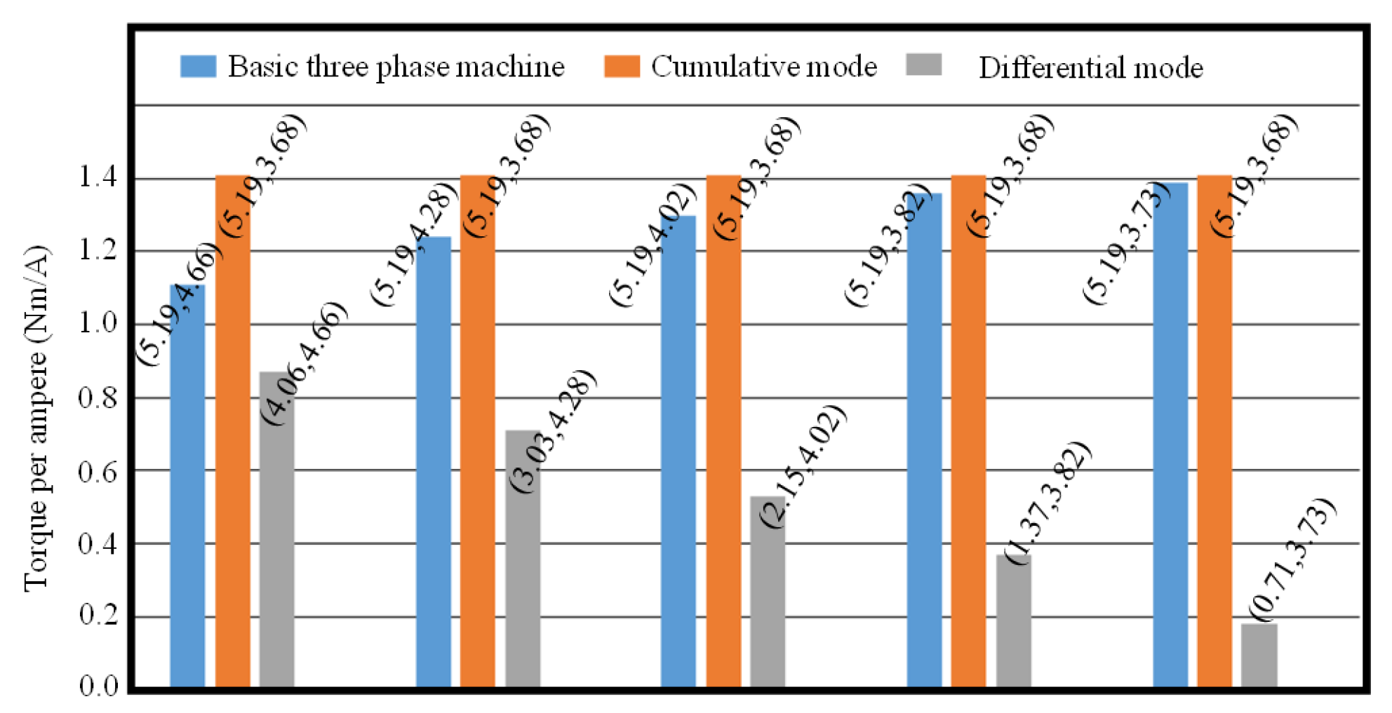
Figure 21.
Simulation results for control strategy-I (a) output torque (b) dq0 currents and (c) currents of phase A and X.
Figure 21.
Simulation results for control strategy-I (a) output torque (b) dq0 currents and (c) currents of phase A and X.
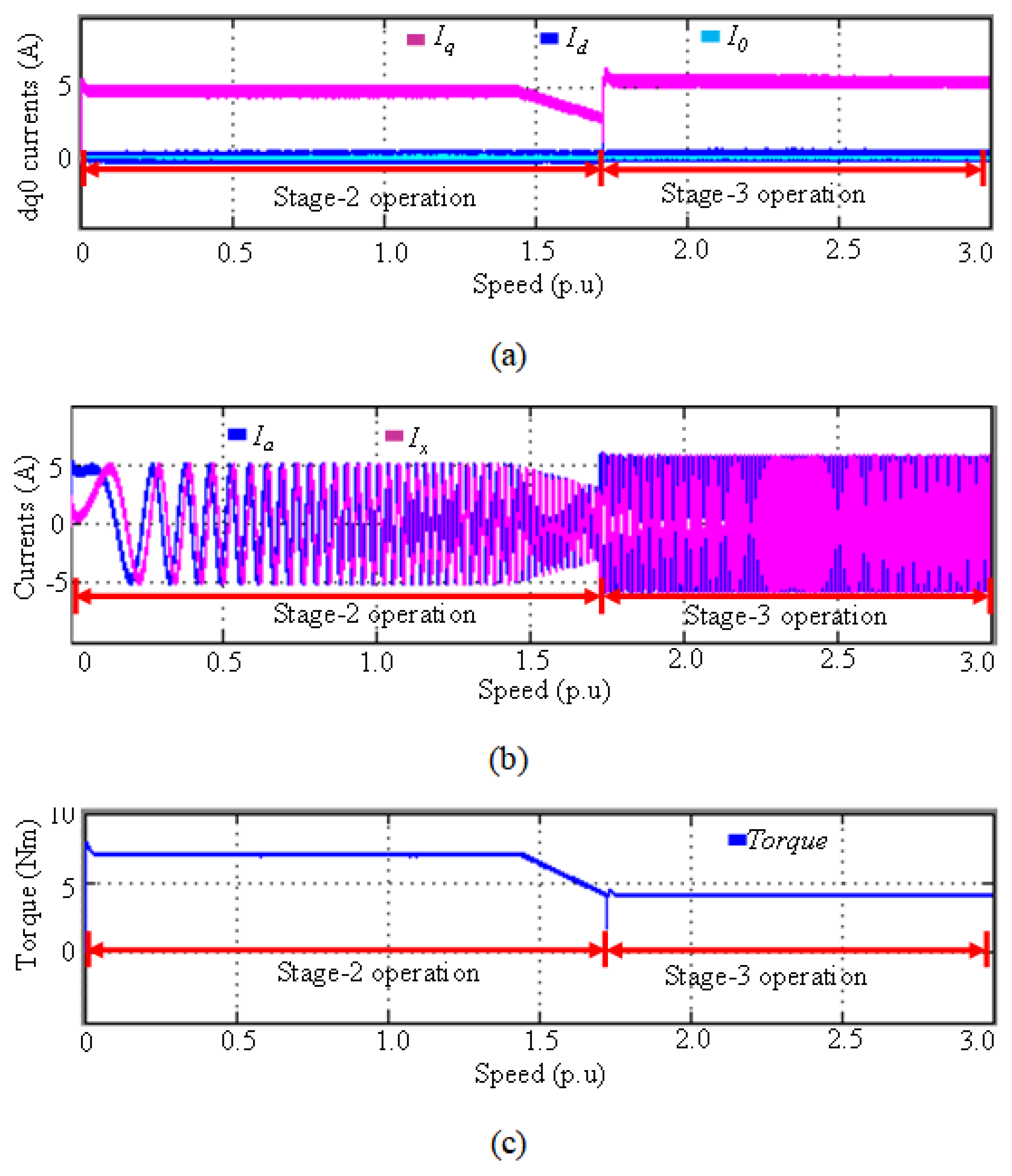

Table 1.
Summary of the machine design-II simulation results.
| Model | Angle | Calculated fw | Simulated fw | Delay Angle | AdvanceAngle |
|---|---|---|---|---|---|
| Model-I | 1.30 | 1.27 | |||
| Model-II | 1.73 | 1.70 | |||
| Model-III | 2.41 | 2.37 | |||
| Model-IV | 3.73 | 3.63 | |||
| Model-V | 7.59 | 7.34 |
Disclaimer/Publisher’s Note: The statements, opinions and data contained in all publications are solely those of the individual author(s) and contributor(s) and not of MDPI and/or the editor(s). MDPI and/or the editor(s) disclaim responsibility for any injury to people or property resulting from any ideas, methods, instructions or products referred to in the content. |
© 2024 by the authors. Licensee MDPI, Basel, Switzerland. This article is an open access article distributed under the terms and conditions of the Creative Commons Attribution (CC BY) license (http://creativecommons.org/licenses/by/4.0/).
Copyright: This open access article is published under a Creative Commons CC BY 4.0 license, which permit the free download, distribution, and reuse, provided that the author and preprint are cited in any reuse.


