Submitted:
27 August 2025
Posted:
27 August 2025
You are already at the latest version
Abstract
Amid the global shift towards sustainable energy, generators are pivotal for efficient and clean energy use. This study introduces an interior double-radial asymmetric permanent magnet (PM) and salient-pole electromagnetic hybrid excitation generator to tackle the challenges of flux adjustment in traditional permanent magnet synchronous generators (PMSGs) and the low power density of electrically excited generators (EEGs). This study theoretically derives equations for the no-load induced electromotive force, voltage adjustment range, and total harmonic distortion (THD) by analyzing generator parameter relationships. Optimization parameters include the offset angles of the double-layer asymmetric PM and the structural parameters of the salient-pole rotor. A multi-objective optimization model is developed with objectives including the no-load induced electromotive force amplitude, voltage adjustment range, and THD. Latin Hypercube Sampling (LHS) is employed to generate samples, followed by sensitivity analysis of optimization parameters. Pareto front analysis and defined parameter matching coefficient are then used to screen the optimization parameters. The optimal magnet pole parameters have been identified. The optimized design results in an 18.7% increase in no-load induced electromotive force amplitude, a 17.6% expansion in voltage adjustment range, and a 38.2% reduction in THD. Finally, a prototype is fabricated and tested. The results confirmed the accuracy of theoretical analysis and the effectiveness of optimization method. The output characteristics of designed generator are significantly improved.
Keywords:
hybrid excitation generator
; asymmetric permanent magnet
; multi-objective optimization
; pareto front
1. Introduction
The depletion of fossil fuels presents significant challenges, including energy shortages, global warming, and environmental pollution. In response, the global focus has shifted toward the development and utilization of renewable and clean energy sources. Generators, as crucial energy conversion devices, are widely used in applications such as wind power, tidal energy, and electric vehicles [1]. Currently, generators are primarily categorized into PMSGs and EEGs PMSGs offer high power density and efficiency but face challenges with inflexible air gap magnetic flux adjustments, leading to unstable output voltage and complex flux-weakening control over wide speed ranges [2,3]. Conversely, EEGs, which produce magnetic fields via excitation windings, allow field strength regulation by adjusting excitation current but suffer from high excitation losses, slow dynamic response, and low output efficiency [4,5]. To address these limitations, hybrid excitation generators (HEGs) have been developed, integrating the benefits of both PM and electrically excited windings. HEGs facilitate dynamic control of air gap magnetic flux through excitation current adjustments, achieving high efficiency and excellent controllability, and have thus become a significant research focus [6-8].
HEGs can be classified into parallel and series types according to their magnetic circuit structures [9]. In parallel structures, the PM circuit and the electrically excited circuit remain independent, offering advantages such as strong independence in magnetic field regulation, prevention of irreversible PM demagnetization, and continued PM operation in the event of excitation winding failures. However, this configuration involves complex magnetic circuit design, is prone to excessive magnetic leakage and mutual coupling between excitation sources, and requires independent design of dual magnetic circuits, thereby increasing generator volume and weight while reducing space utilization efficiency [10,11]. In contrast, series structures use PM as the main magnetic source and electrically excited windings as the auxiliary source, enabling flexible adjustment of the air gap magnetic flux through series-coupled magnetic circuits. This design not only simplifies the structure and effectively suppresses magnetic leakage and coupling effects, but also eliminates the redundant magnetic circuit design present in parallel structures, thereby reducing generator volume and weight while enhancing space utilization efficiency. Furthermore, through the coordinated design of the main and auxiliary excitation sources, the power density of generators is further enhanced [12,13].
Gu et al. [14] introduce an axial parallel hybrid excitation DC generator comprising a PM generator and a flux modulation generator, featuring double coaxial rotors. By examining parameters like rotor offset angle and adjusting the magnetic flux phase difference between the components, they achieved a notable increase in output voltage over a specific load range. However, the flux modulation generator employs interior excitation windings alongside armature windings within the stator slots, leading to an excessively high slot fill factor. Variations in excitation current significantly interfere with the armature windings' induced electromotive force through mutual inductance, thereby impacting voltage stability. Geng et al. [15] introduce a hybrid excitation generator featuring an electromagnetic rotor combined with an embedded PM rotor. Through optimization of parameters like the PM rotor structure and the electromagnetic rotor's axial length, they attained broad magnetic field adjustability and stable voltage output. Nevertheless, the dual rotors substantially increase the axial length, resulting in a larger overall volume and diminished power density. Gong et al. [16] introduce a hybrid excitation synchronous generator with parallel rotor structure, using Halbach array PM rotor and non-salient-pole electrically excited rotor in coaxial parallel structure. By studying parameters such as the rotor axial length and the ratio of slot number to division number in the electrically excited rotor, they achieved constant voltage output and reduced the voltage waveform distortion rate. However, Halbach array PM are relatively brittle and easily damaged during installation, and the slotted structure of the electrically excited rotor increases the complexity of air gap permeance calculation. Wang et al. [17] introduce a hybrid excitation doubly salient generator featuring separated windings, achieved by inserting PM into the stator slots. This design employs interior PM in stator slot magnetic bridges to ensure insulation between the excitation and armature windings, thus establishing parallel magnetic circuits between the PM and the electrically excited components. By comparing three generation modes and optimizing parameters like the rotor slot ratio and PM size, the researchers enhanced the generator's capability for wide-speed-range constant voltage output, as well as its efficiency and reliability. However, the interior PM placement between double windings complicates the stator structure and manufacturing process. Additionally, the absence of experimental validation limits the confirmation of the optimization method's effectiveness, as it relies solely on simulation results. Zhang et al. [18] introduce a brushless reversed claw pole electromagnetic PM hybrid excitation generator featuring interior combined PM in the rotor. The design employs electrically excited claw poles in a reversed configuration, with their tips directed toward the PM rotor. By optimizing parameters such as the claw pole tip width and thickness angles, they attained a broad voltage adjustment range and enhanced the amplitude of the induced electromotive force. and decreased THD. Nonetheless, manufacturing variable cross-section claw poles poses challenges, and incomplete magnetic circuit decoupling during reverse excitation distorts the induced electromotive force waveform. Yu et al. [19] introduce a dual-direction hybrid excitation brushless DC generator featuring an interior combined PM within an interleaved claw pole rotor. By examining parameters like double three-phase and three-phase winding connections and the excitation magnetomotive force adjustment range, and integrating 3D finite element simulations with prototype testing, they effectively adjusted the air gap magnetic flux and enhanced output voltage. However, this structure imposes a significant computational burden in 3D finite element simulations, and the double three-phase winding design complicates manufacturing. Qiao et al. [20] introduce a hybrid excitation brushless claw-pole alternator, featuring an annular PM between the claw poles. Positioned between the double claw poles, the interior annular PM is secured by excitation brackets that attach the excitation windings to the end covers. By optimizing parameters such as the PM outer diameter and thickness, they enhanced the average air gap magnetic density and facilitated flux adjustment with minimal excitation current. However, the interior annular PM may increase local magnetic leakage between the claw poles and necessitate a larger reverse excitation current during flux-weakening adjustments. Xiong et al. [21] introduce a hybrid excitation generator featuring dual excitation windings, where axially segmented PM are concentrated in the central full-PM region and the double-end alternate-pole areas. The stator core houses bilateral annular symmetric excitation windings. Through an accurate subdomain model that accounts for stator slot effects and computes parameters like PM remanence and slot width, they precisely calculate the no-load air gap magnetic density distribution. Nonetheless, this model is based on idealized assumptions and lacks prototype fabrication for empirical validation.
While previous studies have improved magnetic modulation, optimized output voltage, and reduced harmonic distortion, they often face challenges such as complex manufacturing, extended axial length, and limited power density. Additionally, none have explored enhancing output via a double-radial asymmetric PM structure [22,23]. This paper introduces an interior double-radial asymmetric PM and salient-pole electromagnetic hybrid excitation generator. The double-layer asymmetric PM is embedded within the salient-pole rotor core, creating a double-radial asymmetric permanent magnet magnetic field (PMMF). Excitation windings in the rotor core generate an electrically excited magnetic field (EEMF), with PMMF and EEMF coupled in series within the magnetic circuit. By optimizing parameters like the offset angles of the double-layer PM and the salient-pole rotor's structural parameters, we achieve improved no-load induced electromotive force amplitude, an expanded voltage adjustment range, and reduced THD. This generator combines high power density with adaptable magnetic field control. Furthermore, it aims to enhance the conversion of renewable energy into electricity, acting as a clean energy carrier and contributing to global carbon neutrality goals.
2. Hybrid Excitation Generator Design Mechanism
2.1. Hybrid Excitation Generator Structure Design
This study presents the design of an interior double-radial asymmetric PM and salient-pole electromagnetic hybrid excitation generator, as depicte1d in Figure 1. Figure 1(a) illustrates the generator's overall structure, comprising armature windings, excitation windings, lower and upper PM, rotor core, and stator core. Figure 1(b) details the rotor magnet pole parameters, with α1, α2, β1 and β2 representing the offset angles of the lower and upper PM, and ws, hs, wb and hb as the structural parameters of the salient pole rotor. The hybrid excitation generator's main parameters are derived using empirical formulas, as listed in Table 1. The double-layer asymmetric PM is integrated within the salient-pole rotor core to produce a double-radial asymmetric PM magnetic field, while excitation windings on the rotor core body generate the electromagnetic excitation magnetic field. The stator core employs a double-layer distributed short-pitch winding design, effectively suppressing higher harmonics, enhancing the fundamental amplitude, and improving the sinusoidal quality of the induced electromotive force waveform.
This study presents a cooperative design integrating interior double-layer PM with salient-pole electrically excited windings, achieving high power density and adaptable flux adjustment. By varying the offset angles of the interior double-layer PM to create a double-radial asymmetric PM circuit, the design enhances the primary magnetic flux density and reduces THD. The electrically excited windings modulate the excitation current to provide dynamic magnetic field compensation, ensuring stable voltage output across varying operating conditions, mitigating core saturation, and enhancing power density [24].
2.2. Magnetic Circuit Analysis of Hybrid Excitation Generator
The hybrid excitation generator primarily employs an interior double-layer PM as the main magnetic source, with electrically excited windings to modulate the magnetic field strength. PMMF and EEMF are series-coupled within the magnetic field. In analyzing the magnetic circuit, it is assumed that the magnetic resistances of the stator and rotor cores are negligible, magnetic saturation is disregarded, and leakage fluxes from the ends of the double-layer PM, as well as from the pole shoe and pole body, are considered separately. Boundary effects are also neglected [25]. The magnetic circuit distribution of the generator is depicted in Figure 2.
Figure 2 depicts that the generator’s primary magnetic flux arises from two excitation sources: the interior double-layer PM and the electrically excited windings. The PM serves as the primary magnetic source, while the electrically excited windings provide auxiliary magnetic support. The interior double-layer PM is engineered to ensure that their magnetic flux lines couple in series. The upper PM facilitates the flux from the lower PM to traverse the air gap and engage with the stator core, thereby augmenting the overall magnetic flux. By introducing a positive or negative current to the electrically excited windings, the air gap’s magnetic field strength can be modulated, either increasing or decreasing the total magnetic flux. The red solid line represents the primary magnetic circuit, comprising a series coupling of the PM magnetic circuit and the electrically excited magnetic circuit across the air gap. The flux path originates at the N-pole of the lower PM, traverses the salient-pole rotor core, passes through the S-pole and N-pole of the upper PM, continues through the salient-pole rotor core and main air gap, and engages with the stator core. It then re-crosses the main air gap via the opposite end’s salient-pole rotor core, the S-pole and N-pole of the upper PM, the salient-pole rotor core, and the S-pole and N-pole of the lower PM, ultimately returning to the S-pole of the initial lower PM through the salient-pole rotor core. The green solid line represents the leakage flux circuit, primarily comprising three segments located at the ends of the double-layer PM and between the pole shoes and pole bodies of adjacent magnet poles. Utilizing the superposition principle, the equivalent magnetic circuit diagram of the hybrid excitation generator is derived from its magnetic circuit distribution, as depicted in Figure 3.
As depicted in Figure 3, Fe, Fb, Fa and Fd are the magnetomotive forces of electrically excited windings, lower PM, upper PM and generator direct-axis reaction respectively; Ge, Gb and Ga are the internal permeances of electrically excited windings, lower PM and upper PM respectively; Geδ, Gbδ and Gaδ are the effective permeances of electrically excited windings, lower PM and upper PM respectively; Ges, Gbs and Gas are the stator core permeances corresponding to electrically excited windings, lower PM and upper PM respectively; Ger1 and Ger2 are the leakage permeances of magnetic field through pole body and pole shoe respectively; Gbl and Gal are the end leakage permeances of lower PM and upper PM respectively; Φe, Φb and Φa are the main magnetic fluxes provided by electrically excited windings, lower PM and upper PM respectively; Φer1 and Φer2 are the leakage magnetic fluxes of magnetic field through pole body and pole shoe respectively; Φeδ, Φbδ and Φaδ are the effective magnetic fluxes of electrically excited windings, lower PM and upper PM respectively; Φbl and Φal are the end leakage magnetic fluxes of lower PM and upper PM respectively.
Based on Kirchhoff’s law and related magnetic circuit analysis methods, the magnetic flux equations can be expressed as:
In the analysis, the generator is assumed to be in a no-load state with the direct-axis magnetomotive force set to zero. The air gap magnetic field in the hybrid excitation generator, as designed in this study, comprises both PMMF and EEMF. This field directly affects the generator’s three-phase no-load induced electromotive force. The air gap permeance reflects the magnetic flux conduction capacity within the air gap; higher permeance implies lower magnetic reluctance. Consequently, the air gap magnetic flux and magnetic density can be expressed by the following equations:
where Φδ is the total air gap magnetic flux; Bδ is the total air gap magnetic flux density; Aδ is the cross-sectional area of air gap; Aeδ, Abδ and Aaδ are the cross-sectional areas through which the magnetic flux densities generated by electrically excited windings, lower PM and upper PM pass the air gap respectively. The equations for Abδ and Aaδ can be expressed as:
where τ1 and τ2 are the included angles between lower PM and upper PM respectively.; r is the radius of rotor core; L is the axial length of rotor core; α1 and α2 are the respective offset angles of lower PM; β1 and β2 are the respective offset angles of upper PM.
The magnitude of air gap magnetic flux is jointly determined by factors such as magnetomotive force, the cross-sectional area through which magnetic flux passes when entering the air gap, and magnetic circuit material characteristics [26]. Based on Formulas (4) and (5), when the offset angle of PM in rotor core changes, the cross-sectional areas through which upper PM and lower PM pass the air gap change accordingly, thereby influencing the magnitude of air gap permeance. Therefore, the equation for the air gap permeance can be expressed as:
where δ is the air gap length; µ0 is the vacuum permeability. Based on Formulas (4) – (7), parameters in the respective offset angles of the interior double-layer PM influence the spatial distribution of the air gap permeance, thereby affecting the harmonic content of the air gap magnetic flux density.
Given the equal width and thickness of both sides of the interior double-layer PM, magnetic flux leakage is typically concentrated at the ends. Considering the end leakage permeance collectively, the equations for leakage permeance of the interior double-layer PM, as well as the adjacent salient pole rotor core pole shoes and pole bodies, are expressed as:
where σ0 is the leakage coefficient; µr is the permeability of the rotor core; ws and hs are the pole shoe width and height of the rotor core, respectively; wb and hb are the pole body width and height of the rotor core, respectively; µ1 and µ2 are the permeability of the lower PM and upper PM, respectively; h1 and h2 are the thickness of the lower PM and upper PM, which are set to 2 mm and 1 mm in this paper, respectively; Abl and Aal are the leakage cross-sectional area of the lower PM and upper PM, respectively. The equations for Abl and Abl can be expressed as:
Therefore, the equation for the induced electromotive force of the generator in the no-load state can be expressed as:
where Em is the no-load induced electromotive force of generator; f is the rated frequency; N is the number of armature winding turns, which is set to 11 turns in this paper; Kdp is the armature winding coefficient; KΦ is the waveform coefficient of total air gap magnetic flux. By substituting Formulas (1) – (2) and (4) – (10) into Formula (13), the no-load induced electromotive force equation can be expressed as:
In HEGs, the voltage adjustment range of the no-load induced electromotive force is defined by the difference between its maximum and minimum values. These values result from the air gap magnetic flux variations caused by applying the maximum excitation current in alignment with the PMMF to enhance the flux, and the maximum reverse excitation current to weaken it [27]. This indicates the generator’s capability to adjust the air gap magnetic field strength bidirectionally through the excitation current. The numerical value quantifies the dynamic adjustment range of the no-load induced electromotive force. Consequently, the equation for calculating this voltage adjustment range can be expressed as:
where △El is the voltage adjustment range of no-load induced electromotive force; Φδmax is the maximum value of total air gap magnetic flux; Φδmin is the minimum value of total air gap magnetic flux.
The sinusoidality of generator no-load induced electromotive force waveform is quantitatively evaluated through THD. This indicator is defined as the percentage of square root of sum of squares of effective values of each harmonic except fundamental wave to effective value of fundamental wave, and is the core parameter for measuring the degree of waveform deviation from sinusoidality [28]. After Fast Fourier Transform (FFT) of no-load induced electromotive force waveform, the THD equation can be expressed as:
where Em1 is the effective value of no-load induced electromotive force fundamental wave; Emi is the effective value of no-load induced electromotive force i-th harmonic (i=2, 3, 4, …).
Changes in the parameters of no-load induced electromotive force affect the amplitude and phase of the fundamental wave and its harmonics, as determined by FFT, thereby altering the THD [29]. A lower THD suggests that the waveform of the no-load induced electromotive force closely approximates an ideal sinusoid. Additionally, higher harmonic components disrupt the precision of excitation current adjustments on the air gap magnetic field, increasing voltage control deviation within the no-load voltage adjustment range. Notably, during bidirectional adjustment of the excitation current, higher-order harmonics reduce the effective adjustment range of the fundamental amplitude, leading to unexpected fluctuations in the no-load induced electromotive force during voltage adjustments. Thus, effective THD control is crucial for improving the generator’s output performance.
Based on the above theoretical analysis, from the analytical equations of Em, △El and THD, when generator structural parameters are determined, the respective offset angles of PM α1, α2, β1 and β2 and salient pole rotor structural parameters ws, hs, wb and hb change, directly influencing Em, △El and THD. Because there are strong and complex coupling effects among various parameters, which significantly influence Em, △El and THD, multi-parameter and multi-objective collaborative optimization method needs to be used for analysis.
3. Electromagnetic Performance Optimization Analysis
3.1. Sensitivity Analysis
In generator design, changes in various parameters significantly influence its performance, and these parameters are interdependent with complex coupling effects. Traditional single-parameter optimization methods hardly consider the interactions between parameters comprehensively, and cannot achieve effective improvement of generator comprehensive performance. Therefore, to address the performance optimization challenges arising from multi-parameter coupling in generators, a multi-objective and multi-parameter optimization framework is established in this study. Based on the above analysis, eight parameters are selected for optimization, including the respective offset angles of the interior double-layer PM α1, α2, β1 and β2 and the salient-pole rotor structural parameters ws, hs, wb and hb. Considering the constraints of manufacturing technology and structural dimensions, the value ranges of these optimization parameters are listed in Table 2.
In the initial design phase, dealing with the high-dimensional space of eight optimization parameters, directly using surrogate models to link these parameters with optimization objectives often compromises model accuracy. This approach risks overlooking less sensitive parameters due to dimensional redundancy [30]. Additionally, multi-objective optimization algorithms become more complex and computationally intensive with numerous parameters, hindering convergence. Sensitivity analysis can quantify the relationships between parameters and objectives, thus refining qualitative analyses and avoiding the limitations of single-variable assessments. This provides more precise and comprehensive quantitative insights for identifying key parameters and optimizing models. This study employs LHS to generate samples, ensuring uniform coverage of each parameter’s marginal distribution via stratified sampling. This method effectively prevents sample clustering and achieves efficient space filling with fewer samples. In this design, 200 sample points are generated, with sensitivity calculations based on linear correlation expressed as [31]:
where |ξ| is the absolute value of linear correlation between optimization parameter X and optimization objective Y; Q is the number of sample points; ηX and ηY are the expected values of optimization parameter and optimization objective, respectively; λX and λY are the standard deviation of optimization parameter and optimization objective, respectively.
Sensitivity analysis effectively pinpoints optimization parameters that significantly impact generator performance, thereby minimizing redundant experiments, cutting computational costs, and enhancing optimization efficiency. Figure 4 depicts the sensitivity of optimization parameters to optimization objectives. The offset angle of the lower PM, positioned at the forefront of the magnetic circuit series coupling, exerts a pronounced effect on electromagnetic performance with angle variations. The pole shoe width, which directly dictates the effective cross-sectional area of the main air gap permeance path, exhibits high sensitivity. Conversely, the offset angle of the upper PM, affected by magnetic circuit series coupling and leakage flux, depicts a marked decline in magnetic field regulation efficiency. The widths and heights of the pole body and pole shoe, constrained by the magnetic circuit series coupling, contribute minimally to the main permeance, resulting in lower sensitivity. To streamline computational complexity, parameters ws, α1, α2, which have a greater impact on optimization objectives, are selected for further analysis. Finite element simulations determine the final values of the remaining optimization parameters.
To validate the sensitivity analysis, actual and predicted values for three response optimization objectives were compared, and a response residual plot was generated, as depicted in Figure 5. The sample points cluster near the black diagonal line and predominantly fall within the red boundary, demonstrating a high reliability of the predicted values in relation to the actual values.
To facilitate the calculation of the fitting curve, this study selects two optimization parameters with higher sensitivity influence on optimization objectives for analysis. By calculating the Residual Sum of Squares (RSS) and the Total Sum of Squares (TSS) of the samples, the equations for RSS and TSS are expressed as follows:
where RMSE is the root mean square error, CoD is the coefficient of determination. The calculation results are listed in Table 3. The RSS percentages of Em, △El and THD are all less than 5%, indicating that the accuracy of the sensitivity analysis of optimization parameters to optimization objectives in this design can be verified to be high.
This paper uses response surface method to investigate the relationships between optimization parameters and optimization objectives, as depicted in Figure 6, Figure 7 and Figure 8. Figure 6 and Figure 7 are the response surfaces of the pole shoe width ws interacting with the offset angles α1 and α2 of the lower PM with respect the optimization objectives, respectively. When ws is within a small range, Em, △El and THD simultaneously reach their peak values on the response surface. After that, as ws increases, Em, △El and THD all show a trend of first decreasing to a minimum and then increasing. Figure 8 is the response surface of the offset angles α1 and α2 of the lower PM with respect to the optimization objectives. The influence of α1 and α2 on the optimization objectives depicts a nonlinear relationship. Therefore, the dynamic changes of the optimization objectives are dominated by the interactions among ws, α1 and α2. Analysis of these three optimization parameters can effectively enhance the generator’s output characteristics.
3.2. Multi-objective Optimization and Verification
The optimization objectives of this paper are Em, △El and THD, which belong to multi-objective optimization problem. Evolutionary Algorithm (EA) are employed for optimization, serving as an intelligent search method for multi-objective optimization by mimicking biological evolution mechanisms. By leveraging principles like natural selection, inheritance, and mutation, EA efficiently address conflicting optimization problems across multiple performance indicators without necessitating complex analytical models. This approach adeptly manages the nonlinear relationships between generator parameters and performance [32]. This study aims to find the maximum values of Em and △El and the minimum value of THD; therefore, the generator optimization model can be expressed as:
Based on this optimization model, an EA is used to construct a three-dimensional Pareto front distribution with 500 sample points, as depicted in Figure 9 [33]. The Pareto front details the trade-off relationships among the optimization objectives Em, △El, and THD. Green points are all sample points, while red points are Pareto front sample points that satisfy constraint conditions. The relatively optimal solution is selected from the red points, and the corresponding data are listed in Table 4.
To identify a set of relatively optimal solution sample points from the Pareto front distribution, a parameter matching coefficient, c, is defined for analysis. A larger value of c indicates better corresponding generator performance [34]. The equation for assigning weights to the three optimization objectives is expressed as:
where t1, t2 and t3 are the weighting coefficients, with t1 set to 0.5, t2 set to 0.1, and t3 set to 0.3. Em0 = 14.97V is the amplitude, △El0 = 4.66V is the voltage adjustment range, and THD0 = 5.32% is the THD of no-load induced electromotive force before optimization. The calculated values of parameter matching coefficient equation are depicted in Figure 10. Considering parameter rationality and manufacturability, a set of relatively optimal solution sample points that satisfy the optimization model equation is identified as 359, with a maximum value of 0.43. After substituting the screened parameter values into finite element simulation software for comprehensive optimization, the remaining parameter values are obtained, and the comparison of generator parameters before and after optimization is listed in Table 5.
To verify the effectiveness of the optimization design, the hybrid excitation generator both before and after optimization is subjected to finite element simulation, and the changes in Em, △El and THD are compared, as depicted in Figure 11, Figure 12 and Figure 13. In Figure 11, the red curve is the optimized Em = 17.77V, which is increased by 18.7% compared to before optimization. In Figure 12, the difference between blue points on the red curve is the optimized △El = 5.48V, which is increased by 17.6% compared to before optimization. FFT of the no-load induced electromotive force is performed. The red bars in Figure 13 depict that the fundamental amplitude after optimization is significantly increased, while the amplitudes of other harmonics are reduced. Using Formula (16), the THD is calculated as 3.29%, corresponding to a 38.2% reduction compared to before optimization. In summary, using the interior double-radial asymmetric PM and the optimized salient pole rotor structural parameters effectively enhances the amplitude and voltage adjustment range of the no-load induced electromotive force and reduces its THD, thereby verifying the effectiveness of the optimization method.
4. Experimental verification
To verify the validity of the finite element simulation, a prototype of a three-phase, 8-pole, 36-slot interior double-radial asymmetric PM and salient-pole electromagnetic hybrid excitation generator is fabricated, as depicted in Figure 14. The generator comprehensive performance test platform consists of a DC regulated power supply, a generator performance test bench, current transformers, a sliding rheostat, a digital bridge, an oscilloscope, a power analyzer, and a current transformer power supply. The equipment layout of the experimental platform is depicted in Figure 15.
The generator performance test comprises two stages: the no-load test and the load test. During the no-load test, the generator is operated at a specified speed using the motor belt on the test bench to ensure stability. A DC regulated power supply injects positive and negative currents into the generator's excitation windings, facilitating effective coupling of the PMMF and EEMF. An oscilloscope captures the no-load induced electromotive force waveform from the armature windings, measuring its amplitude and voltage adjustment range. The oscilloscope's FFT function decomposes the waveform to determine each harmonic's amplitude, subsequently calculating the THD using the appropriate formula. During the load test, the sliding rheostat's resistance is adjusted under circuit discharge conditions to set the load, with resistance measured by a digital bridge. The generator speed is adjusted using the generator performance test bench, while a DC regulated power supply delivers positive and negative currents to the excitation windings. During wiring, one generator output terminal connects in series with a sliding rheostat via a current transformer, powered by its own supply, while the other terminal connects directly to the rheostat to complete the circuit. The voltage probe of the power analyzer is connected in parallel across the rheostat to measure voltage. The current transformer relays the detected current signal to the power analyzer for synchronous measurement, enabling calculation of the generator's output power.
Based on the generator comprehensive performance test platform, the generator speed is stabilized at the rated speed of 4000 r/min. The amplitude of the no-load induced electromotive force, the voltage adjustment range, and the THD of the prototype are measured, as depicted in Figure 16, Figure 17 and Figure 18. At the rated speed, the measured results of the prototype are Em = 17.5 V, △El = 5.3 V and THD = 3.4%, respectively. A slight discrepancy exists between the measured and simulated values, which can be attributed to factors not considered in the simulation, such as the assembly process and generator friction losses. However, the trends of variation are consistent, falling within the acceptable error range.
To dynamically match the generator with varying load powers at rated speed, stable output voltage is controlled by adjusting the excitation current, as depicted in Figure 19. Experimental results indicate that with increasing load current, generator output power increases, and the excitation current necessary for maintaining stable voltage rises almost linearly. Specifically, at a load current of 37.1 A and an excitation current of -1.2 A, the generator operates at half-load with an output power of 250 W. When the load current reaches 43.8 A and the excitation current is adjusted to -0.2 A, the generator operates at partial load with an output of 350 W. At a load current of 52.2 A and an excitation current of 1.7 A, the generator operates at rated load with an output power of 500 W.
The above test results verify that the interior double-radial asymmetric PM and salient pole electromagnetic hybrid excitation generator introduced in this study has excellent output characteristics. It satisfies the design requirements, and the effectiveness and validity of the introduced design method are verified through experiments.
5. Conclusions
This study introduces an interior double-radial asymmetric PM and salient-pole electromagnetic hybrid excitation generator. First, based on the equivalent magnetic circuit method, the effects of the offset angles of the interior double-layer asymmetric PM and the structural parameters of the salient pole rotor on generator performance are analyzed. The equations for the three optimization objectives, Em, △El, and THD, are deduced. Second, eight optimization parameters are initially selected for sensitivity analysis, with ws, α1 and α2 identified as the main optimization parameters. The remaining parameters are determined via finite element simulation to obtain their final values. Subsequently, EA is used to construct the Pareto front distribution, and the relatively optimal solution suitable for the optimization model is found through the parameter matching coefficient. Then, Em, △El, and THD are compared before and after optimization. The results indicate that after optimization, Em = 17.77 V, △El = 5.48 V, and THD = 3.29%. Compared with before optimization values, Em and △El increase by 18.7% and 17.6%, respectively, while THD decreases by 38.2%. Finally, a prototype is fabricated based on the optimized parameters for experimental validation. The experimental results are generally consistent with the simulation outcomes, and the deviations fall within an acceptable range, thereby verifying the accuracy of the theoretical analysis and the effectiveness of the optimization design. Therefore, the hybrid excitation generator structure designed in this paper provides a promising solution for achieving high-performance power generation. It enhances energy utilization efficiency, reduces operational costs, and contributes to sustainable development.
Author Contributions
Conceptualization, S.M. and C.L.; methodology, S.M. and C.L.; software, C.L.; validation, S.M., C.L., Q.G. and C.Z.; formal analysis, H.B., S.M. and C.L.; Investigation, S.M. and C.L; Resources, S.M.; writing—original draft, C.L.; funding acquisition, S.M. All authors have read and agreed to the published version of the manuscript.
Funding
This research was funded by the Tianjin Education Commission Research Program Project, grant number 2022KJ122.
Institutional Review Board Statement
Not applicable.
Informed Consent Statement
Not applicable.
Data Availability Statement
The original contributions presented in the study are included in the article, further inquiries can be directed to the corresponding author.
Conflicts of Interest
The authors declare no conflicts of interest.
References
- Zhao, Y.; Mo, C.; Zhu, W.; Chen, J.; Wu, B.; Zhang, X.; Zhang, X.; Chen, L. Design and Test for a New Type of Permanent Magnet Synchronous Generator Applied in Tidal Current Energy System. Sustainability 2023, 15, 7378. [Google Scholar] [CrossRef]
- Fang, H.; Wang, D. A Novel Design Method of Permanent Magnet Synchronous Generator From Perspective of Permanent Magnet Material Saving. IEEE Transactions on Energy Conversion 2017, 32, 48–54. [Google Scholar] [CrossRef]
- Zhang, X.; Du, Q.; Ma, S.; Geng, H.; Hu, W.; Li, Z.; Liu, G. Permeance Analysis and Calculation of the Double-Radial Rare-Earth Permanent Magnet Voltage-Stabilizing Generation Device. IEEE Access 2018, 6, 23939–23947. [Google Scholar] [CrossRef]
- Zhong, H.; Zuo, S.; Wu, X.; Wu, S.; Sun, H. Analytic Model of Air Gap Magnetic Field and Radial Electromagnetic Force for Electric Excitation Claw Pole Alternator. Transactions of China Electrotechnical Society 2017, 32, 49–58. [Google Scholar] [CrossRef]
- Shi, L.; Han, Z.; Zhou, X.; Zhang, W.; An, J.; Yan, B. Electromagnetic characteristics analysis of E-core stator doubly salient electro-magnetic generator with short circuit. Electric Machines and Control 2020, 24, 109–119. [Google Scholar] [CrossRef]
- Zhang, Z.; Wang, D.; Hua, W. Overview of Configuration, Design and Control Technology of Hybrid Excitation Machines. Proceedings of the CSEE 2020, 40, 7834–7850. [Google Scholar] [CrossRef]
- Zhang, X.; Du, Q.; Ma, S.; Xu, J.; Geng, H. Development of Hybrid Excitation Generator for Vehicles. Automotive Engineering 2017, 39, 822–826. [Google Scholar] [CrossRef]
- Gu, X.; Zhang, Z.; Sun, L.; Yu, L. Phase Displacement Characteristics of a Parallel Hybrid Excitation Brushless DC Generator. IEEE Transactions on Energy Conversion 2020, 35, 875–885. [Google Scholar] [CrossRef]
- Zhang, Y.; Zhang, X.; Ren, J.; Yan, S.; Wang, L.; Pang, X.; Liu, W.; Kong, Z. Study of Electromagnetic Characteristics of Brushless Reverse Claw Pole Electromagnetic and Permanent Magnet Hybrid Excitation Generator for Automobiles. IEEE Transactions on Energy Conversion 2024, 39, 1288–1300. [Google Scholar] [CrossRef]
- Geng, W.; Zhang, Z.; Yu, L.; Yan, Y. Operation Principle and Flux Regulation Characteristics of a New Parallel Hybrid Excitation Blushless DC Machine. Transactions of China Electrotechnical Society 2013, 28, 131–137. [Google Scholar] [CrossRef]
- Qiao, D.; Wang, X.; Zhu, C. Investigation of Flux Regulation Performance and Experimental Validation of Novel Hybrid Excitation Brushless Claw-pole Alternators. Proceedings of the CSEE 2013, 33, 115–121. [Google Scholar] [CrossRef]
- Zhao, C. Structure Designing and Characteristic Study of HECPG Which Magnetic Circuit Series Connection. Transactions of China Electrotechnical Society 2009, 24, 1–6. [Google Scholar] [CrossRef]
- Mörée, G.; Leijon, M. Overview of Hybrid Excitation in Electrical Machines. Energies 2022, 15, 7254. [Google Scholar] [CrossRef]
- Gu, X.; Zhang, Z.; Sun, L.; Yu, L. Magnetic Field Enhancement Characteristic of an Axially Parallel Hybrid Excitation DC Generator. IEEE Transactions on Magnetics 2021, 57, 1–5. [Google Scholar] [CrossRef]
- Geng, H.; Zhang, X.; Tong, L.; Ma, Q.; Xu, M.; Zhang, Y.; Wang, L. Performance Optimization Analysis of Hybrid Excitation Generator With the Electromagnetic Rotor and Embedded Permanent Magnet Rotor for Vehicle. IEEE Access 2021, 9, 163640–163653. [Google Scholar] [CrossRef]
- Gong, H.; Zhang, Y.; Wang, L.; Zhao, Y.; Hu, L.; Zhang, C. Research on Rotor Pole Matching for Hybrid Excitation Synchronous Generator with Parallel Rotor Structure. Electric Machines and Control 2020, 24, 128–137. [Google Scholar] [CrossRef]
- Wang, M.; Kou, B.; Zhang, L.; Zhao, Y.; Xu, J. A Novel Hybrid Excitation Doubly Salient Generator with Separated Windings by PM Inserted in Stator Slot for HEVs. Energies 2022, 15, 7968. [Google Scholar] [CrossRef]
- Zhang, Y.; Zhang, X.; Ren, J.; Yan, S.; Wang, L.; Pang, X.; Liu, W.; Kong, Z. Study of Electromagnetic Characteristics of Brushless Reverse Claw Pole Electromagnetic and Permanent Magnet Hybrid Excitation Generator for Automobiles. IEEE Transactions on Energy Conversion 2024, 39, 1288–1300. [Google Scholar] [CrossRef]
- Yu, J.; Cao, Y.; Zhu, S.; Liu, C. Analysis of Operation Characteristics for Dual-Direction Hybrid Excitation Brushless DC Generator. Transactions of China Electrotechnical Society 2019, 34, 4634–4641. [Google Scholar] [CrossRef]
- Qiao, D.; Wang, X.; Zhu, C. Study on a hybrid excitation brushless claw-pole alternator with an annular PM between the claw poles. Journal of Electric Machines and Control 2014, 18, 30–35. [Google Scholar] [CrossRef]
- Xiong, Y.; Zhao, J.; Yan, S.; Wei, K. Analytical Calculation of the No-Load Magnetic Field of a Hybrid Excitation Generator. Electronics 2024, 13, 2574. [Google Scholar] [CrossRef]
- Wang, L.; Zhang, X.; Wu, J.; Wang, M.; Hu, W.; Geng, H.; Pang, X. Multi-Objective Optimization Design of a Segmented Asymmetric V-Type Interior Permanent Magnet Synchronous Motor. IEEE Transactions on Magnetics 2025, 61, 1–12. [Google Scholar] [CrossRef]
- Qiao, Z.; Shi, L.; Li, F.; Xu, H.; Zhou, T.; Wang, W. Characteristics Analysis of Magnetic-Pole-Shift in an Asymmetric Hybrid Pole-Permanent Magnet-Assisted Synchronous Reluctance Motor. IEEE Journal of Emerging and Selected Topics in Power Electronics 2025, 13, 1394–1405. [Google Scholar] [CrossRef]
- Xiao, Y.; Zhu, Z.Q.; Jewell, G.W.; Chen, J.; Wu, D.; Gong, L. A Novel Asymmetric Rotor Interior Permanent Magnet Machine With Hybrid-Layer Permanent Magnets. IEEE Transactions on Industry Applications 2021, 57, 5993–6006. [Google Scholar] [CrossRef]
- Li, J.; Wang, K.; Zhu, S.; Liu, C. Consequent-pole Hybrid Excitation Brushless DC Generator Based on Integrated Induction. Proceedings of the CSEE 2022, 42, 4209–4218. [Google Scholar] [CrossRef]
- Gao, F.; Li, X.; Qi, X.; Tao, C.; Gao, P. Analysis of torque ripple of the interior permanent magnet synchronous motor with asymmetric V-pole offset. Electric Machines and Control 2021, 25, 112–120. [Google Scholar] [CrossRef]
- Zhu, C.; Wang, X.; Yang, Y.; Shen, Y.; Yu, P.; Zhang, G. Structure and Voltage Regulation Analysis of a Parallel Hybrid Excitation Synchronous Generator Based on Double-pole Induction. Proceedings of the CSEE 2020, 40, 7890–7898, 8226. [Google Scholar] [CrossRef]
- Shi, L.; Yan, B.; Zhang, W.; An, J.; Ding, F.; Bian, Y. Electromagnetic characteristics analysis of electric excitation segmental rotor flux-switching generator. Journal of Electric Machines and Control 2021, 25, 110–118. [Google Scholar] [CrossRef]
- Zhu, L.; Jiang, S.Z.; Zhu, Z.Q.; Chan, C.C. Analytical Modeling of Open-Circuit Air-Gap Field Distributions in Multisegment and Multilayer Interior Permanent-Magnet Machines. IEEE Transactions on Magnetics 2009, 45, 3121–3130. [Google Scholar] [CrossRef]
- Gao, F.; Gao, J.; Li, M.; Yao, P.; Song, Z.; Yang, K.; Gao, X. Optimization Design of Halbach Interior Permanent Magnet Synchronous Motor Based on Parameter Sensitivity Stratification. Journal of Xi’an Jiaotong University 2022, 56, 180–190. [Google Scholar] [CrossRef]
- Li, S.; Zhou, L.; Wang, X.; Dai, Z. Parameter optimization design of double-layer magnets permanent magnet synchronous motor for vehicles based on multi-round evolutionary algorithm. Science Technology and Engineering 2024, 24, 9891–9898. [Google Scholar] [CrossRef]
- Li, W.; Wang, Z.; Zhang, F. Rotor Strength Optimization of Surface Mount High Speed Permanent Magnet Motor Based on FEM/Kriging Approximate Model and Evolutionary Algorithm. Transactions of China Electrotechnical Society 2023, 38, 936–944, 956. [Google Scholar] [CrossRef]
- Chen, K.; Ma, S.; Li, C.; Wu, Y.; Ma, J. Optimization and Design of Built-In U-Shaped Permanent Magnet and Salient-Pole Electromagnetic Hybrid Excitation Generator for Vehicles. Symmetry 2025, 17, 897. [Google Scholar] [CrossRef]
- Ma, S.; Wu, Y.; Li, C.; Chen, K. Optimization and analysis of interior permanent magnet drive motor with unequal thickness magnetic poles for electric vehicle. Journal of Hebei University of Science and Technology 2025, 46, 375–385. [Google Scholar] [CrossRef]
Figure 1.
Hybrid excitation generator structure: (a) Overall generator structure; (b) Parameter structure of rotor magnet pole.
Figure 1.
Hybrid excitation generator structure: (a) Overall generator structure; (b) Parameter structure of rotor magnet pole.
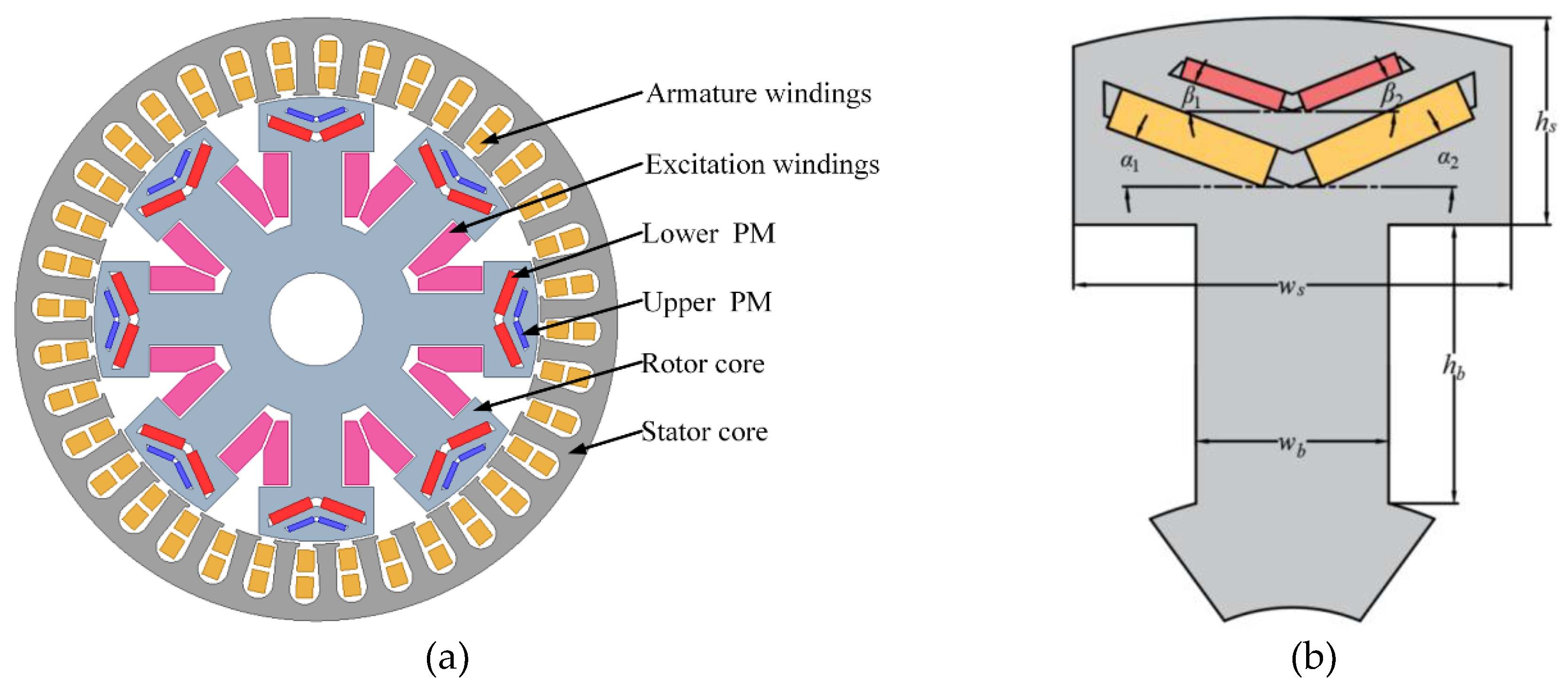
Figure 2.
Magnetic circuit distribution of hybrid excitation generator.

Figure 3.
Equivalent magnetic circuit diagram of hybrid excitation generator.
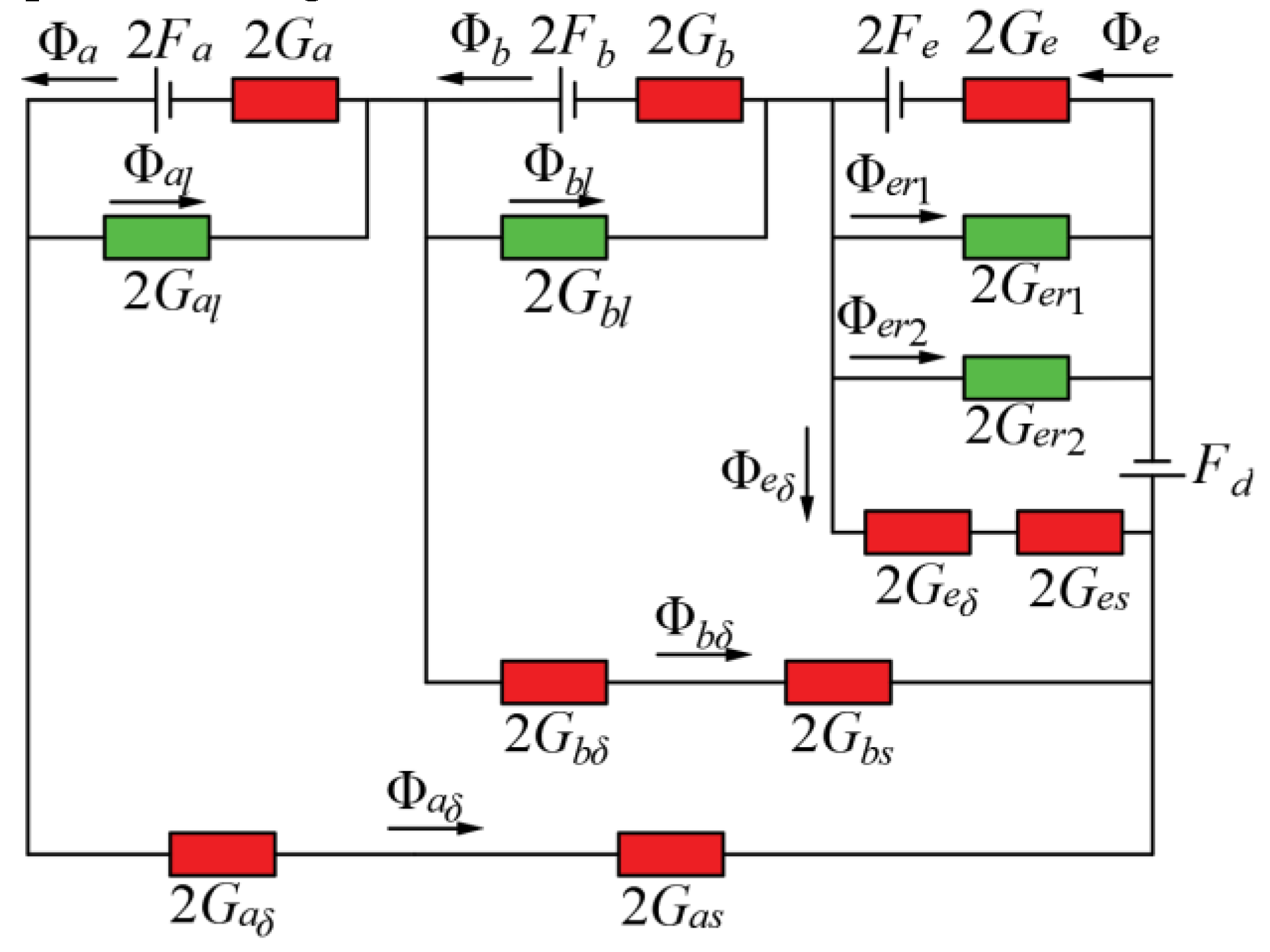
Figure 4.
Sensitivity of optimization parameters to optimization objectives.
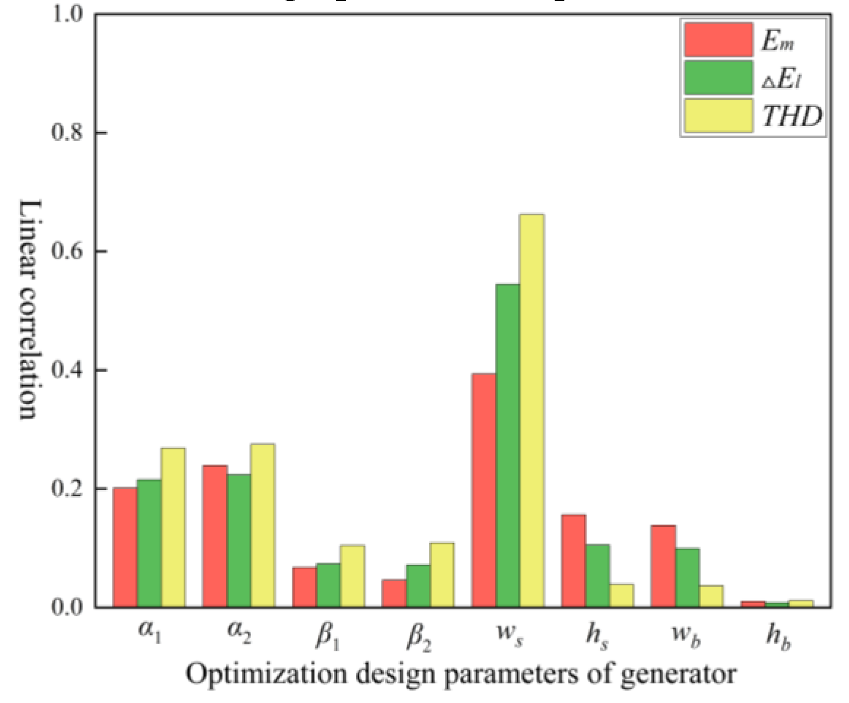
Figure 5.
Response residual diagram: (a) Em; (b) △El; (c) THD
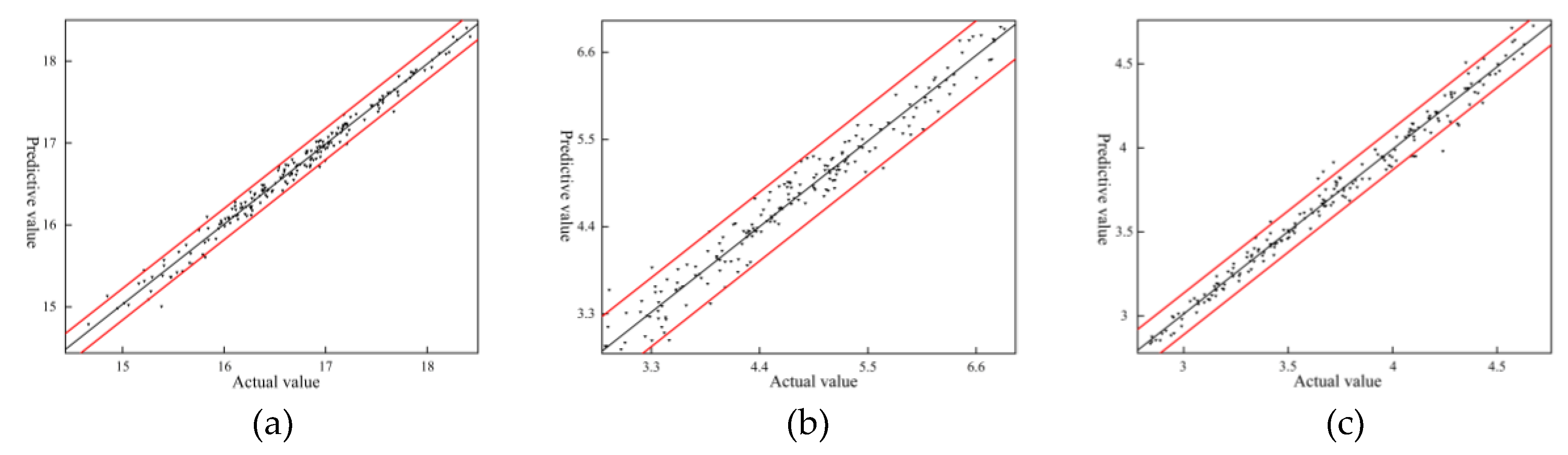
Figure 6.
Response surface of ws and α1with optimization objectives: (a) Effect of ws and α1 on Em; (b) Effect of ws and α1 on △El; (c) Effect of ws and α1 on THD.
Figure 6.
Response surface of ws and α1with optimization objectives: (a) Effect of ws and α1 on Em; (b) Effect of ws and α1 on △El; (c) Effect of ws and α1 on THD.
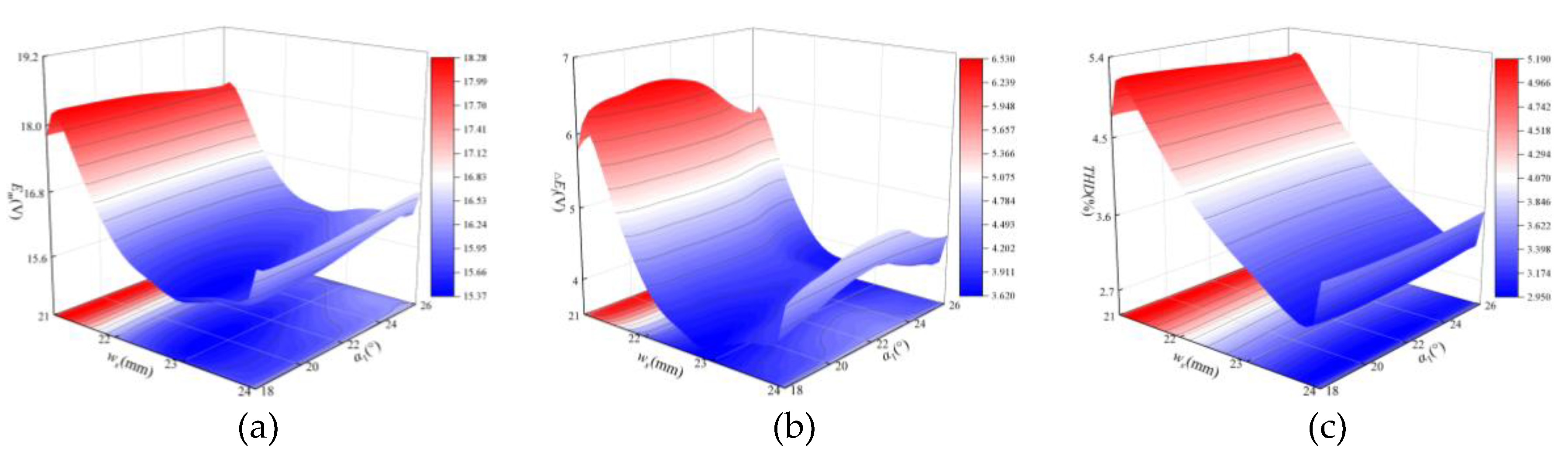
Figure 7.
Response surface of ws and α2with optimization objectives: (a) Effect of ws and α2 on Em; (b) Effect of ws and α2 on △El; (c) Effect of ws and α2 on THD.
Figure 7.
Response surface of ws and α2with optimization objectives: (a) Effect of ws and α2 on Em; (b) Effect of ws and α2 on △El; (c) Effect of ws and α2 on THD.
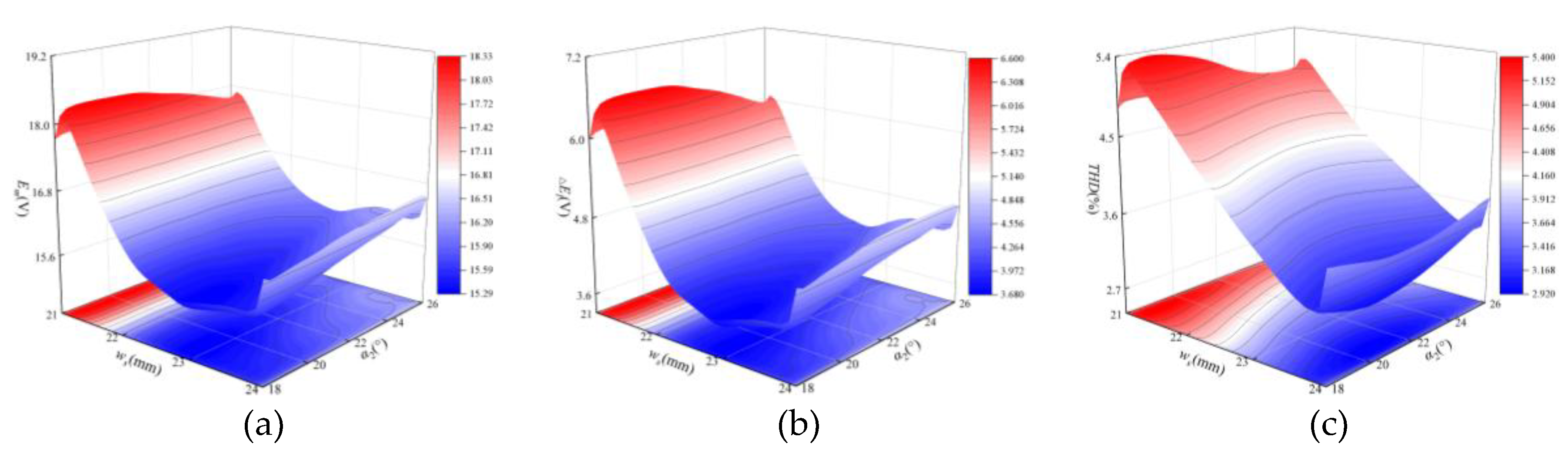
Figure 8.
Response surface of α1 and α2 with optimization objectives: (a) Effect of α1 and α2 on Em; (b) Effect of α1 and α2 on △El; (c) Effect of α1 and α2 on THD.
Figure 8.
Response surface of α1 and α2 with optimization objectives: (a) Effect of α1 and α2 on Em; (b) Effect of α1 and α2 on △El; (c) Effect of α1 and α2 on THD.
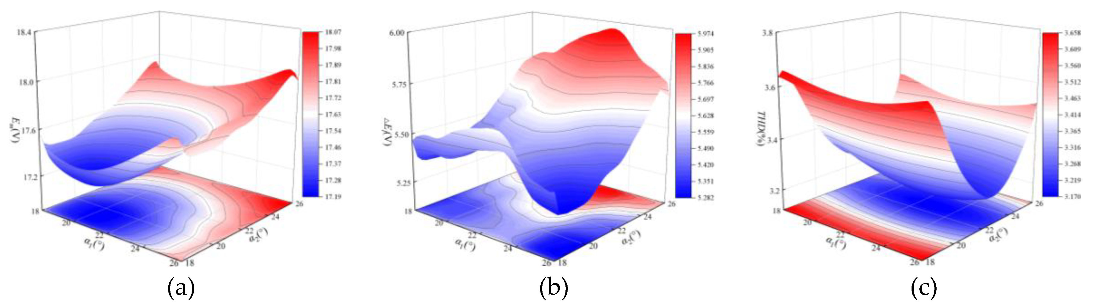
Figure 9.
Pareto front distribution.
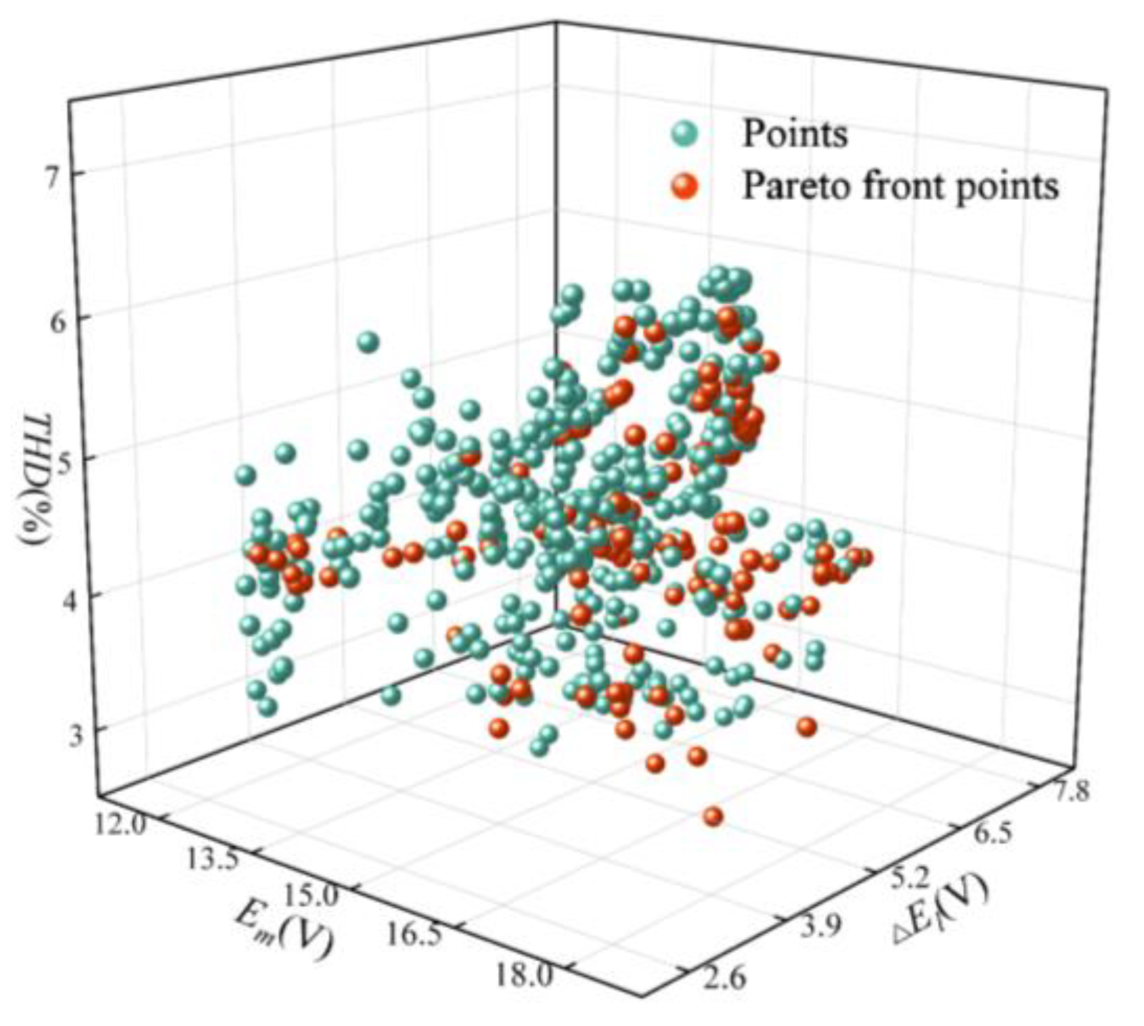
Figure 10.
Parameter matching coefficient statistics.
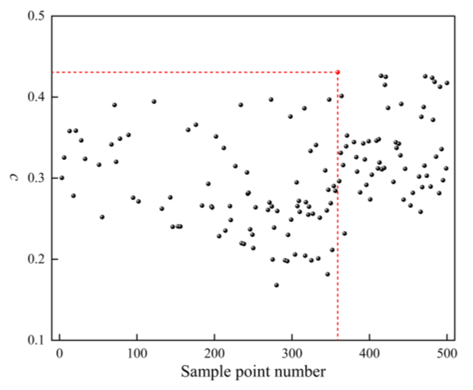
Figure 11.
Comparison of the no-load induced electromotive force before and after optimization.
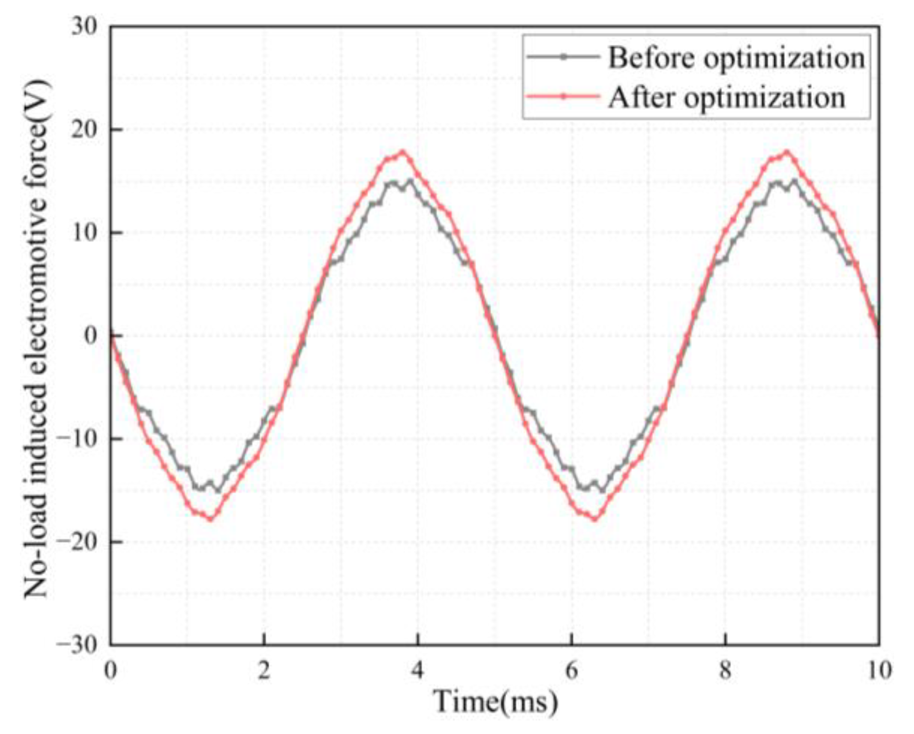
Figure 12.
Comparison of the no-load induced electromotive force voltage adjustment range before and after optimization.
Figure 12.
Comparison of the no-load induced electromotive force voltage adjustment range before and after optimization.
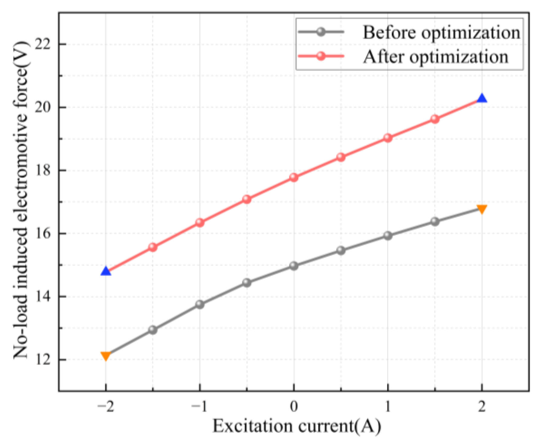
Figure 13.
Comparison of harmonics of the no-load induced electromotive force before and after optimization.
Figure 13.
Comparison of harmonics of the no-load induced electromotive force before and after optimization.
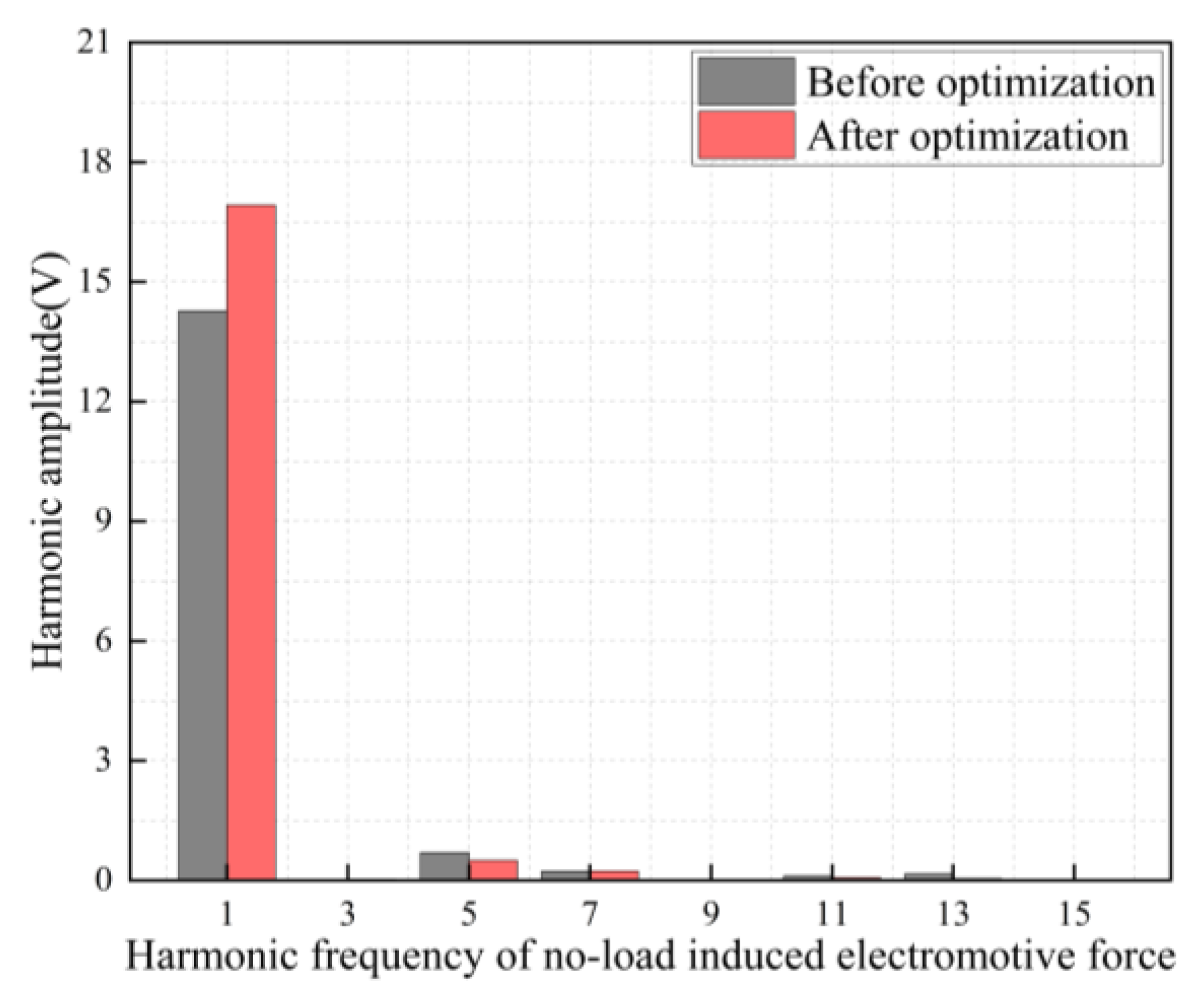
Figure 14.
The diagram of prototype structure: (a) Stator; (b) Rotor.
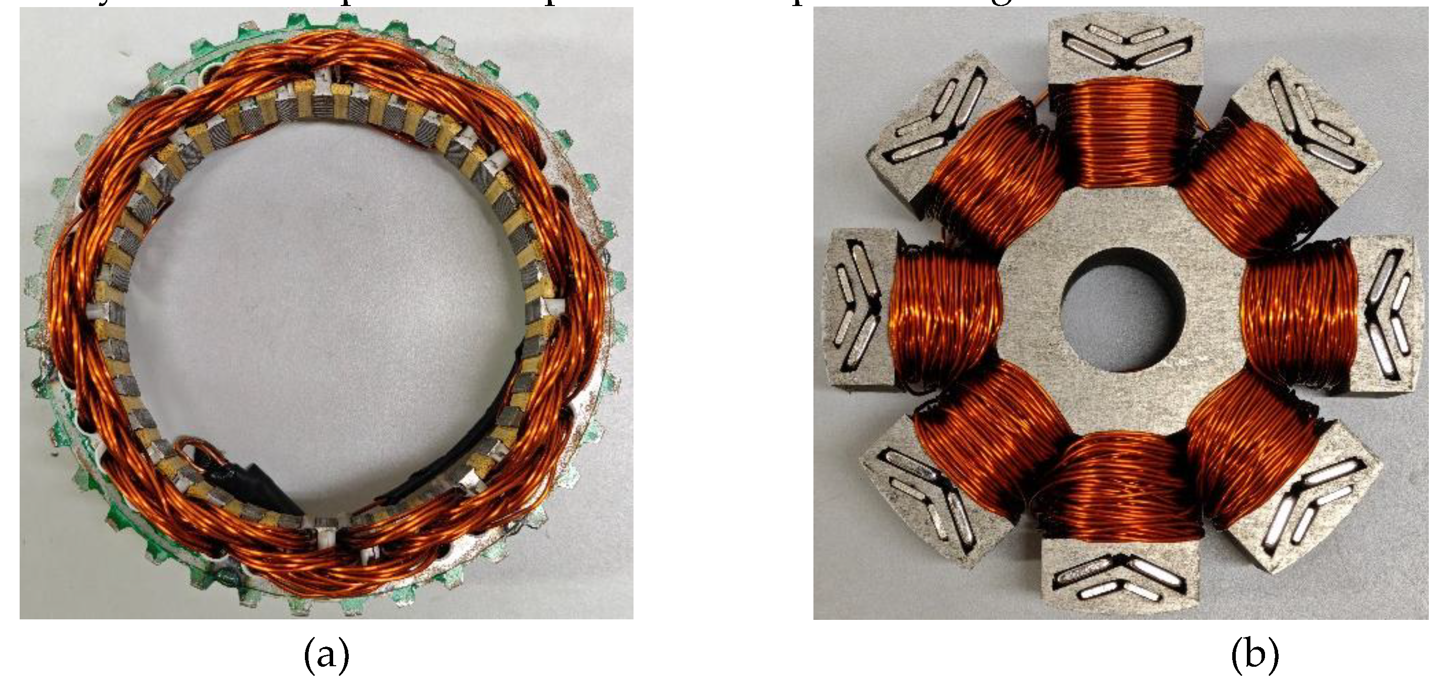
Figure 15.
Generator comprehensive performance test platform.
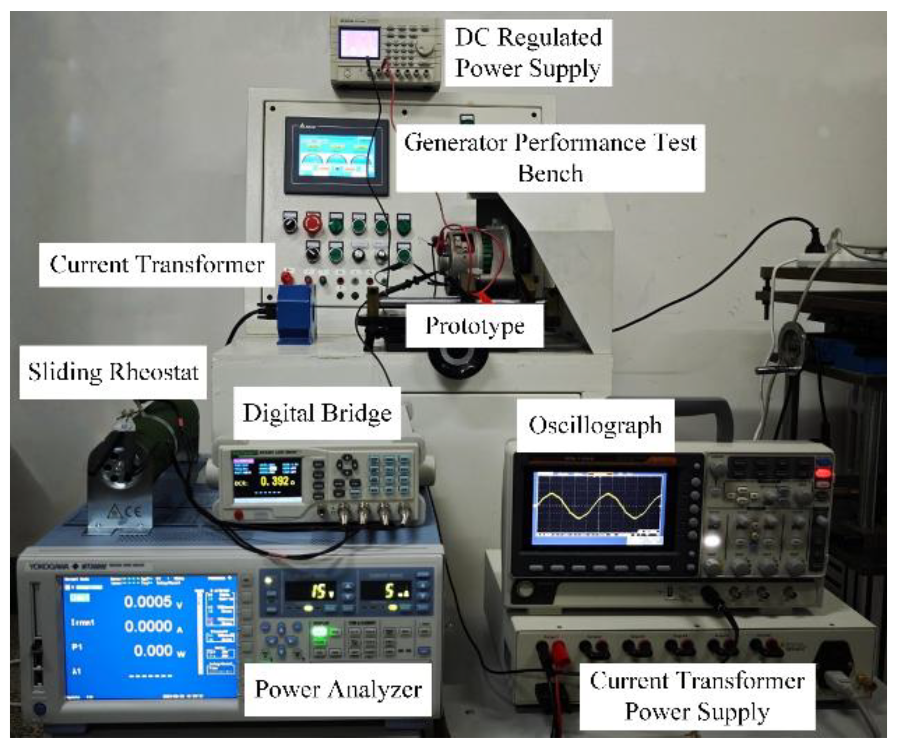
Figure 16.
Experimental results of no-load induced electromotive force.
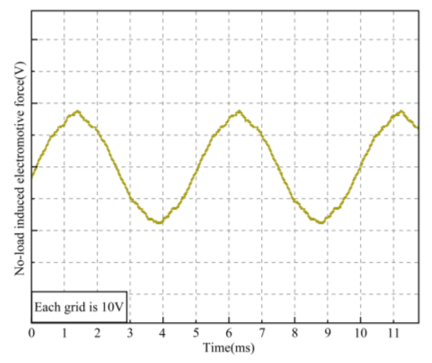
Figure 17.
Experimental results of no-load induced electromotive force voltage adjustment range.
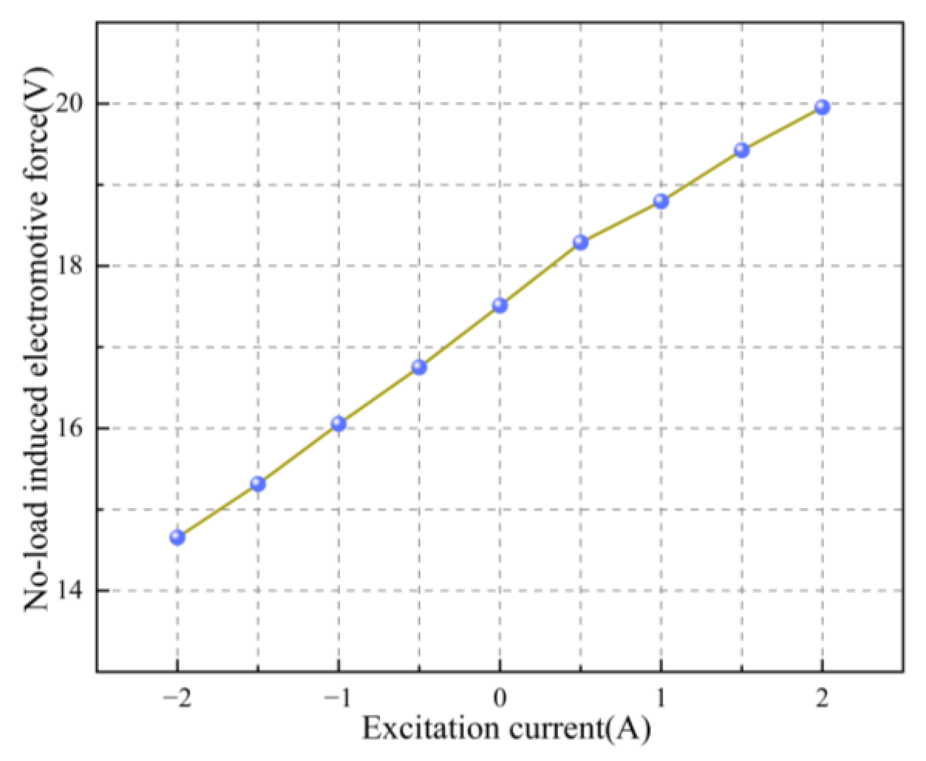
Figure 18.
Experimental results of no-load induced electromotive force voltage adjustment range.
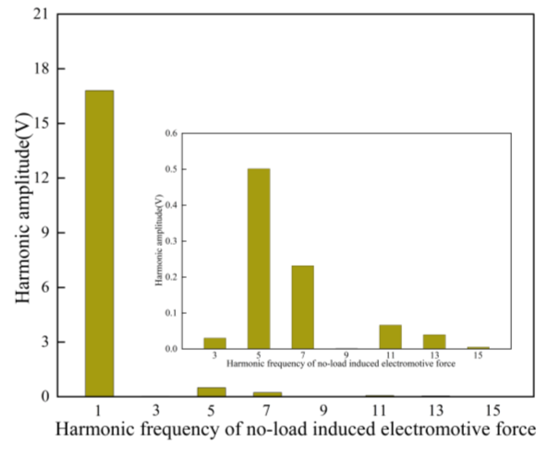
Figure 19.
Experimental results of no-load induced electromotive force voltage adjustment range.
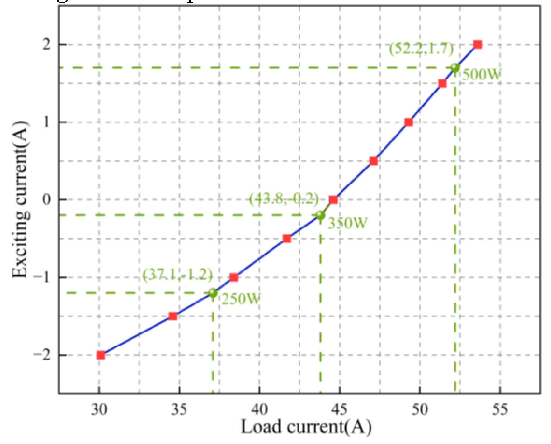

Table 1.
Main parameters of hybrid excitation generator.
| Parameters (Unit) | Value | Parameters (Unit) | Value |
|---|---|---|---|
| Rated power (W) | 500 | Slot number | 36 |
| Rated speed (r/min) | 4000 | Stator outer diameter (mm) | 110 |
| Rated voltage (V) | 14 | Stator inner diameter (mm) | 82 |
| Axial length (mm) | 25 | Rotor outer diameter (mm) | 81 |
| Pole number | 8 | Rotor inner diameter (mm) | 17 |
Table 2.
Value ranges of optimization parameters.
| Parameters (Unit) | Range of values |
|---|---|
| α1(°) | 18~26 |
| α2(°) | 18~26 |
| β1(°) | 17~22 |
| β2(°) | 17~22 |
| ws(mm) | 21~24 |
| hs(mm) | 7.5~11 |
| wb(mm) | 7~10.5 |
| hb(mm) | 13~16.5 |
| entry 2 | data 1 |
Table 3.
Deviation statistics of optimization objectives.
| Optimization objectives | TSS | RSS | Percentage (%) |
|---|---|---|---|
| Em | 347.09 | 4.71 | 1.36 |
| △El | 230.55 | 9.51 | 4.13 |
| THD | 118.18 | 1.82 | 1.54 |
Table 4.
Relative optimal solution set of pareto front distribution.
| Serial numbers | ws (mm) | α1 (°) | α2 (°) | Em (V) | △El (V) | THD (%) |
|---|---|---|---|---|---|---|
| 3 | 21.041 | 20.3825 | 22.518 | 18.159 | 3.840 | 4.918 |
| 6 | 22.169 | 19.963 | 23.183 | 14.025 | 4.851 | 2.991 |
| 13 | 23.266 | 19.403 | 25.523 | 15.989 | 4.677 | 3.325 |
| ··· | ··· | ··· | ··· | ··· | ··· | ··· |
| 495 | 22.212 | 19.513 | 18.868 | 18.312 | 3.813 | 5.022 |
| 499 | 24.110 | 25.989 | 19.041 | 15.579 | 3.674 | 3.513 |
| 500 | 21.402 | 23.062 | 24.666 | 15.961 | 6.916 | 3.142 |
Table 5.
Comparison of generator parameters before and after optimization.
| Parameters | α1 (°) | α2 (°) | β1 (°) | β2 (°) | ws (mm) | hs (mm) | wb (mm) | hb (mm) |
|---|---|---|---|---|---|---|---|---|
| Before optimization | 23.772 | 23.772 | 19.142 | 19.142 | 23.335 | 7.986 | 7.206 | 14.536 |
| After optimization | 20.676 | 24.156 | 18.832 | 21.832 | 21.009 | 9.934 | 9.250 | 13.359 |
Disclaimer/Publisher’s Note: The statements, opinions and data contained in all publications are solely those of the individual author(s) and contributor(s) and not of MDPI and/or the editor(s). MDPI and/or the editor(s) disclaim responsibility for any injury to people or property resulting from any ideas, methods, instructions or products referred to in the content. |
© 2025 by the authors. Licensee MDPI, Basel, Switzerland. This article is an open access article distributed under the terms and conditions of the Creative Commons Attribution (CC BY) license (http://creativecommons.org/licenses/by/4.0/).
Copyright: This open access article is published under a Creative Commons CC BY 4.0 license, which permit the free download, distribution, and reuse, provided that the author and preprint are cited in any reuse.


