
Submitted:
08 September 2025
Posted:
09 September 2025
You are already at the latest version
Abstract
A new energy storage unit, which was fed by a piezoelectric wind energy harvester is explored. The outputs of a three-phase piezoelectric wind energy device have been initially recorded from the laboratory experiments. Following the records of voltage outputs, the power ranges of the device are measured as several hundreds of microWatts. The main issue of the piezoelectric voltage generation is that voltage waveforms of the piezoelectric materials have high total harmonic distortion (THD) with incredibly high subharmonics and superharmonics. Therefore, such a material reply causes a certain power loss at the output of the wind energy generator. In order to fix this problem, we propose a combination of a rectifier and a storage system, where they can operate compatibly under such high THD rates (i.e. 125). Due to high THD values, current - voltage characteristics are not linear-dependent, indeed because of capacitive effect of the piezoelectric (i.e. Lead Zirconium Titanite) material, harvested power from the material is reduced by nearly the factor of 20% in the output. That also negatively affects the storage on the Li-based battery. In order to compensate the output waveform of the device, the waveforms, which are received from the energy harvester device are first rectified by a full-wave-rectifier having a maximum power point tracking (MPPT) unit. To conclude, a better harvesting performance has been obtained by storing the energy into the Li-ion battery under a current-voltage controlled boost converter technique.
Keywords:
energy harvester
; piezoelectric
; converter
; battery
1. Introduction
The main purpose for an energy harvesting device is to have maximum power from the existing vibration energy in the environment with the help of suitable converter systems. Thus, the conversion of power in its maximum rate becomes the most important task in addition to the source, itself. Harvesting usable energy can be used in the operation of low-powered electronic circuits, mobile devices, sensors, etc. Considering the improvement of wearable electronic devices and wireless communication applications, energy harvesters get increasing attention world-widely [1,2,3,4,5,6,7]. Recently, industry and academy focus on harvesting energy from mechanical vibrations by using piezoelectric layers due to the high energy density per volume. The efforts on efficient power generation yield to optimization issues on the electrical load, piezoelectric materials, device geometry and natural frequency since these devices exhibit a hysteresis phenomenon on frequency increase/decrease [8,9,10,11].
Energy harvesting conceptually differs from any energy generation in the sense that harvesters basically focus on the lost forms of surrounding stresses, which affect a compact transformation device by sound, vibration, light, temperature, etc., thereby a capturing mechanism is indeed activated in any harvesting operation rather than generating energy from a high amount of energy source such as traditional resources [1]. Therefore, accumulation of low amount of energy is a vital problem in order to use it, when it is required. Frankly speaking, low power ranges such as μW/mW are frequently encountered in these applications.
Most of the electrical devices use batteries, creating maintenance problems due to the environmental issues or complicated recycling operations. Another important point is that the battery lifetime is short and that can be increased further by harvesters with the ambient sources. Recent advances on wireless and microelectro-mechanical systems technology have proven that frequency-dependence can be neglected by applying additional frequency transforming bodies in small scales [9,12,13], thereby one can increase the efficiency for different frequency regimes, too. That also helps to make alternative designs for the replacement of conventional batteries. Considering the ultra-low power (i.e. μW range) portable electronic devices, usage of conventional batteries as power sources is too limited when it is compared to the working life of the devices. Energy harvesters can assist as a self-power source for the portable devices or wireless sensor networks in this respect [7,14,15,16]. In general, the methods used to obtain electrical energy from mechanical vibrations can be divided into three basic groups as electromagnetic (inductive) [9,17,18,19,20,21], electrostatic (capacitive) [22,23,24] and piezoelectric [25,26,27,28,29,30], where is the most convenient in terms of energy density.
Among various harvesting materials, piezoelectricity exhibits pressure electricity by the variation of potential structure inside a crystalline material. We can count these materials as Rochelle salt, quartz, tourmaline, barium titanate, etc. When a pressure is applied to them in a certain direction, these crystals undergo a deformation, in addition, when an electric field E is applied to the terminals of these materials, as a converse effect, a vibration occurs on the material itself. When a converse effect is applied, these can be used as an actuator, thereby, direct effect can be used as a sensor or energy transducer in that context [31]. According to the detailed works, energy densities of piezoelectric energy harvesters are 3 or 5 times higher than the electrostatic or electromagnetic harvesters [9,32]. With its compact nature, piezoelectric harvesters are widely used for the wireless applications in the industry and daily-life [33,34,35,36]. The main reasons for the wide usage area are easy installation and maintenance [37]. Following the advances in material engineering, production of piezoelectric materials has become cheaper compared to the past decades. This reality in the market also enables the piezoelectric harvesters to find a good place in addition to thermoelectric generators and solar photovoltaics [38]. Although piezoelectric components generate less energy, the output can be conveyed to an electronic device directly or a storage unit [39]. Harvested energy can be usable with converters, however the efficiency of them should be enough to proceed to avoid from the energy losses. Therefore, by using the outputs of three piezoelectric layers, a full bridge rectifier depicted in Figure 1 has been designed and used in energy storage unit (ESU).
When wind puts the turbine into rotation electrical signals from the terminals is created by connecting the harvester body to the piezoelectric material. The signal obtained by vibration of the piezoelectric material is mostly similar to a sinusoidal signal, thereby; a straightening operation will be required before energy can be stored. The generator impedance and receiver impedance should be identical for the maximum power transfer. Although waveforms have high impedances, the receivers and batteries do not have such high impedance values. Strictly speaking, an impedance mismatch exists between the turbine and the receiver. A rectifier and a dc-dc converter is quite common to eliminate impedance mismatch in this regard [40], however, waveforms have highly noisy behavior. Therefore, high THD cause certain power loss at the output of the Piezoelectric wind energy harvester (PWEH) [41,42].
The paper is organized as follows: Section 2 gives a detailed information on the harvester itself and the designed ESU. Section 3 presents the experimental and theoretical details of the combined PWEH and ESU systems. Finally, the concluding remarks and future works are discussed in the Conclusion Section.
2. Harvester Design
Piezoelectric wind energy harvesters (PWEHs) provide very low power values at milliwatts (mW) or microwatts (µW) like some other vibration generators in the literature (). Such vibration generators cannot keep large power outputs during operation [43]. The system we designed and implemented PWEH contains many harmonics that show a very high THD due to non-linear effects, the current and voltage characteristics are not linear, which reduces the energy production efficiency of this source. This article PWEH focuses concentrate on a general control circuit to obtain maximum power and store this energy from a system that contains many harmonics, high THD, and non- linear effects. In order to improve these, an ESU system is designed with the control circuit. This article numerically analyzes the waveforms to use the piezoelectric signals, whose quality is improved with the proposed system, to be rectified and then used from the feeding of low power electronic systems with high efficiency or to be stored when necessary.
2.1. Modeling of Harvester Design
Since the PWEH has 3 piezoelectric materials with various masses, they yield to various natural frequencies. The layers have same length with the mass of 1.4 g and force constant of 380 N/m. Physically, a permanent magnet (PM) stands on the shaft rotating under low wind speeds. This rotation causes the PMS to be repelled and 3 piezoelectric material vibrates with a phase shift of 120 degrees. The PM on the shaft and the other PMs on the layers are not physically contacted, thus that improves the durability and lifespan of the piezoelectrics as seen in Figure 2. According to the experiments with wind tunnel, the harvested power P = 0.2 mW has been reached under low wind speeds such as v=1.75 m/s. Besides, large amount of the power has been stored into the battery.
2.2. Topology of Circuit
Figure 3 shows the general circuitry of the proposed ESU and controller attached to the terminals of PWEH. Initially, the generated voltages are transmitted to the rectifier circuit, afterwards, the rectifier output is forwarded to a dc-dc converter having buck/boost characteristics. A battery is added at the end of the overall system as see in Figure 3. At this point, also a state of charge (SOC) is controlled, too. In the literature, there are some techniques for the estimation of maximum power point (MPP).

Table 1.
Parameters of the converter units.
| Buck Converter | Boost Converter | |
|---|---|---|
| Inductance (L) | 1 mH | 1 mH |
| Capacitance (C) | 1 mF | 1 mF |
| Switching Frequency (f) | 10 kHz | 10 kHz |
| PI Control (P-I) | 200-300 | 200-300 |
| Sample Time (Tss) | 1x10⁻⁶ s | |
| Battery | Li-ion, 0.1Ah, 3.6V | |
MPP can be identified by the half of the open circuit voltage (Voc/2)[44]. In the present work, the MPPT scheme is implemented for the PWEH with a power scale of μW. The proposed MPPT scheme operates well with a good efficiency value for such a high THD generating device.
2.3. Controller
The main circuitry consists of 4 block diagrams (Figure 4): Initially, first one the PWEH device itself. Sample harvested waveforms as an input to the rectifier is shown in Figure 5. Piezoelectric materials have 120 degrees each other for the electrical phase variation; thereby they produce different waveforms depending on their natural frequencies. The second block is the rectifier. It is full-bridge rectifiers which convert AC waveforms to a DC waveform. The third one is the buck converter, where the full-rectified waveform (Vrect) is controlled by the buck converter for the MPPT aim. The last block is a boost converter, where current and voltage are controlled for the battery SOC. The rectifier works as an open circuit (Voc). Then the MPPT obtains the Voc value. This is also stored in a capacitor and then it is utilized as the reference voltage for Vrect. Note that the MPPT governs the DC-DC converter for the regulation of the output waveform at the vicinity of Voc by monitoring the change of Vrect. At the last part, Lithium-ion battery operates as a rechargeable battery type, where Lithium ions move from negative potential to the positive one during the discharge process [45]. These batteries are popular for the portable electronics having the best energy-to-weight ratios, low self-discharge rate, and high open circuit voltage [46].
3. Experimental and Theoretical Work
According to the setup in Figure 2, the harvester operates in a wind tunnel. Each layer has a dimension of 41.3x4.7x1.5 mm. In addition, capacitance and stiffness values are C=12 nF and α=61 N/m, respectively. Data acquisition has been made by an NI USB-6250 card with 16 analog inputs. It can record multiple data sets if it is desired. Each waveform from the harvester layers are forwarded to the circuit blocks. When the system is operated at varying wind speeds, the values of the signals obtained from the piezoelectric layers change with the speed. It has been observed that the system does not work well when the wind speed is greater than 8 m/s. It has been observed that the mechanical design and sensitivity of the system works more smoothly and efficiently at wind speeds between 3-7 m/s. The efficient operation of the designed system at light and medium wind speeds can be considered an advantage. If the system is used as a primary or secondary energy source, it means that it can produce energy even at a very low wind speed and can be stored when desired. Figure 5 shows the state of the piezoelectric signals with the speed when the system is operated at different wind tunnel speeds (2-8 m/s).
A Yokogawa type oscilloscope has also been used in order to follow the outputs of the circuit. Experimental waveforms are shown in Figure 5 and MatLab form is also shown in Figure 6. It is seen that a high (i.e. around 130%) THD value can be the main problem for the rectification. This condition increases the sub-harmonic and super harmonic ingredients of the waveforms and storage of energy is not possible without using an efficient controlled rectification.
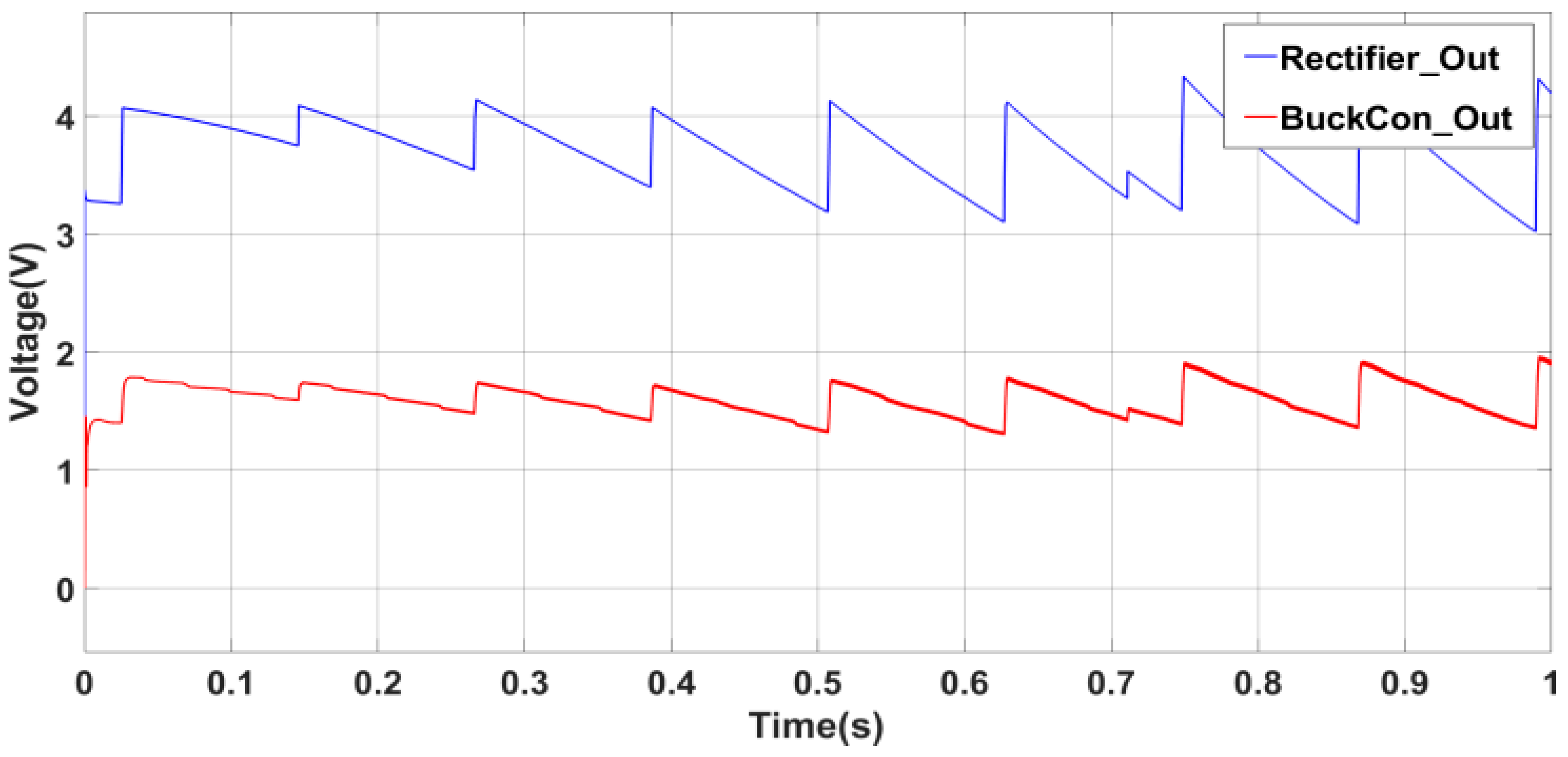
In Figure 7, the rectified waveforms after the rectifier and buck converter are shown. Note that although the voltage values are around 3.5 V and 1.5, current values are low, therefore the power harvested from such systems become in the order of μW scale.
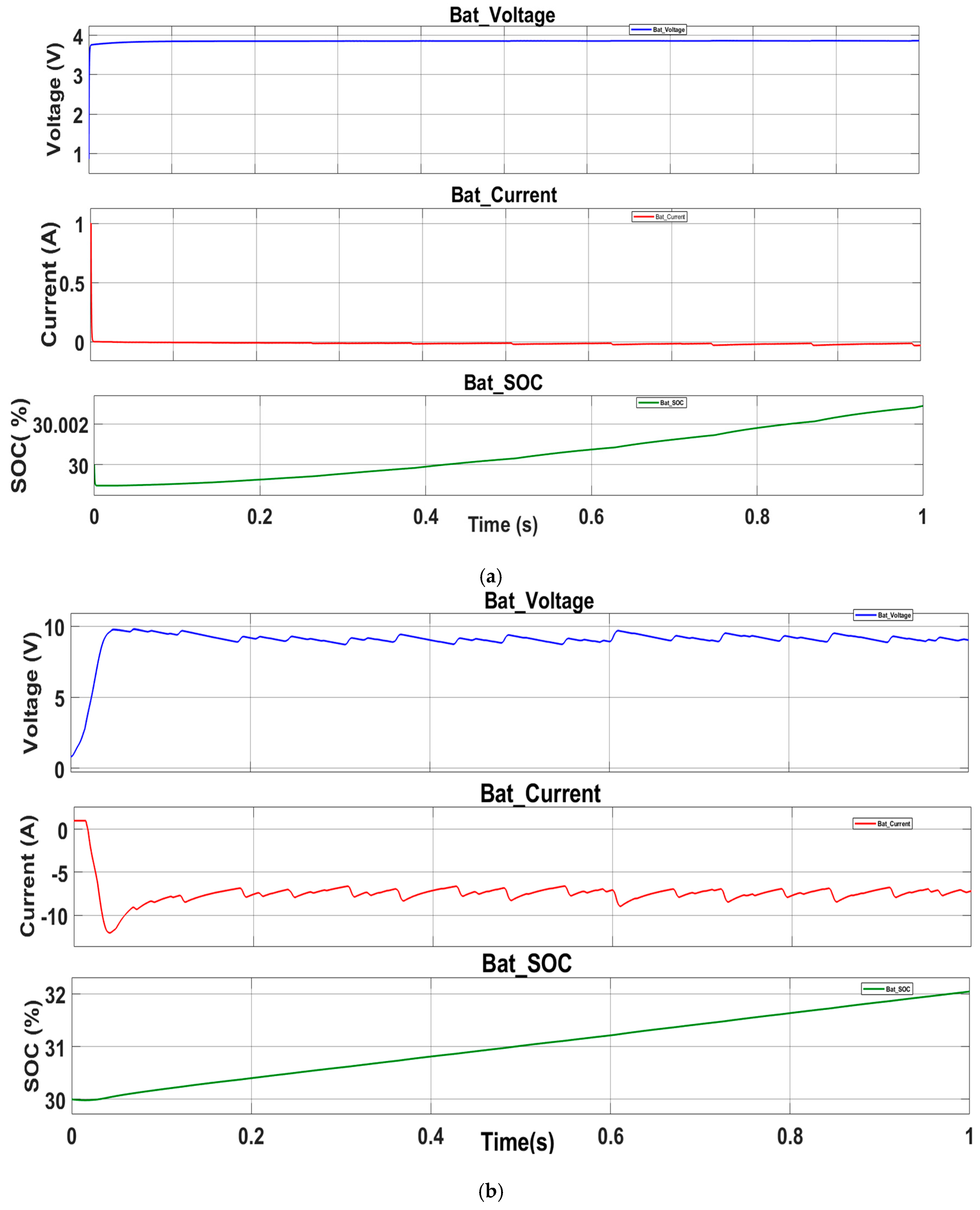
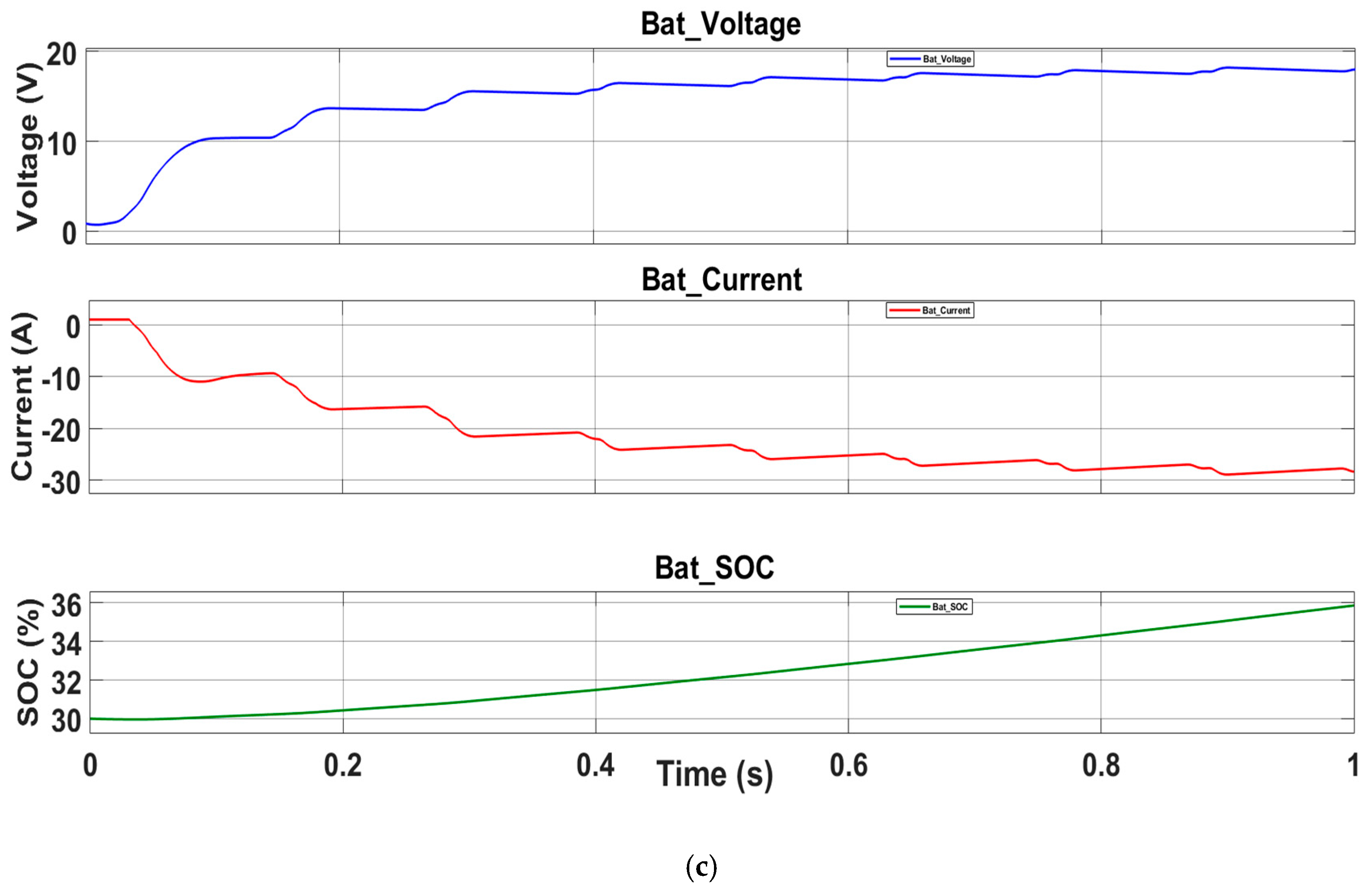
The battery voltage, current and SOC values are shown in multiple plots of Figs. 8(a-c). It is clear that while current decrease by time due to the storage, the controller SOC value increases slowly. In a very short time interval, the output voltage is stabilized for the storage, which is also important for the stability of the circuit.
Figure 8.
Battery charging results for the speeds of a) 2.7 m/s, b) 3.5 m/s, and c) 6.1 m/s.
4. Conclusions
Present work focuses on a controlled storage system for a piezoelectric three phase device. The circuit has a Li-ion battery system for the storage. Waveforms observed in our previous study proved that the waveforms coming from piezo plates had high THD. Thus the first purpose should be decrease of harmonics in the rectification before the battery charging procedure. For this, the waveforms received directly from the piezoelectric plates have been supplied to the buck converter after the rectification to fulfill the Voc/2 control condition. The output signals are filtered with the help of the boost converter with the current-voltage and battery charge status (SOC) values of the battery, then the battery has been charged. The system was operated at different wind speeds and the optimal efficiency was analyzed. The system was found to operate most efficiently at light and medium wind speeds. Due to this operating range, we believe that the system can be easily used in applications that can meet the energy needs of the system or in some of the circuits that require small power. We propose this circuitry to optimize the output energy generation of the proposed wind energy harvester, however that circuitry can be also used for any piezoelectric based energy harvesting devices with highly distorted outputs.
References
- Bizon, N., Tabatabaei, N.M., Blaabjerg, F., Kurt, E., (Eds.), Energy Harvesting and Energy Efficiency: Technology, Methods, and Applications, Springer International Publishing (2017), doi.org/10.1007/978-3-319-49875-1.
- Harne, R.L. and K. Wang, A review of the recent research on vibration energy harvesting via bistable systems. Smart materials and structures, 2013. 22(2): p. 023001. [CrossRef]
- Toprak, A. and O. Tigli, Piezoelectric energy harvesting: State-of-the-art and challenges. Applied Physics Reviews, 2014. 1(3). [CrossRef]
- Siddique, A.R.M., S. Mahmud, and B. Van Heyst, A comprehensive review on vibration based micro power generators using electromagnetic and piezoelectric transducer mechanisms. Energy Conversion and Management, 2015. 106: p. 728-747. [CrossRef]
- Xie, Z., et al., A piezoelectric energy harvester for broadband rotational excitation using buckled beam. Aip Advances, 2018. 8(1). [CrossRef]
- Singla, P. and S.R. Sarangi, A survey and experimental analysis of checkpointing techniques for energy harvesting devices. Journal of Systems Architecture, 2022. 126: p. 102464. [CrossRef]
- Lin, W., et al., Study on human motion energy harvesting devices: A review. Machines, 2023. 11(10): p. 977. [CrossRef]
- Zheng, Y., et al., A Comprehensive Review on Iron-Based Sulfate Cathodes for Sodium-Ion Batteries. Nanomaterials, 2024. 14(23): p. 1915. [CrossRef]
- Uchino, K., Piezoelectric energy harvesting systems—Essentials to successful developments. Energy Technology, 2018. 6(5): p. 829-848. [CrossRef]
- Paul, T., et al., Cube shaped FAPbBr3 for piezoelectric energy harvesting devices. Materials Letters, 2021. 301: p. 130264. [CrossRef]
- Khasawneh, M.A., Energy harvesting devices in pavement structures. Innovative Infrastructure Solutions, 2025. 10(5): p. 183. [CrossRef]
- Friswell, M.I. and S. Adhikari, Sensor shape design for piezoelectric cantilever beams to harvest vibration energy. Journal of Applied Physics, 2010. 108(1). [CrossRef]
- Luo, S.-h., et al., Recent progress and perspective of cathode recycling technology for spent LiFePO4 batteries. Journal of Industrial and Engineering Chemistry, 2024. 133: p. 65-73. [CrossRef]
- Adhikari, S., M.a. Friswell, and D. Inman, Piezoelectric energy harvesting from broadband random vibrations. Smart materials and structures, 2009. 18(11): p. 115005. [CrossRef]
- Kim, H.S., J.-H. Kim, and J. Kim, A review of piezoelectric energy harvesting based on vibration. International journal of precision engineering and manufacturing, 2011. 12: p. 1129-1141.
- Jin, K., et al., Recent progress in aqueous underwater power batteries. Discover Applied Sciences, 2024. 6(8): p. 441. [CrossRef]
- Nechibvute, A., A. Chawanda, and P. Luhanga, Piezoelectric energy harvesting devices: an alternative energy source for wireless sensors. Smart Materials Research, 2012. 2012(1): p. 853481. [CrossRef]
- Glynne-Jones, P., et al., An electromagnetic, vibration-powered generator for intelligent sensor systems. Sensors and Actuators A: Physical, 2004. 110(1-3): p. 344-349. [CrossRef]
- Torah, R., et al. Autonomous low power microsystem powered by vibration energy harvesting. in SENSORS, 2007 IEEE. 2007. IEEE.
- Ambrożkiewicz, B., G. Litak, and P. Wolszczak, Modelling of electromagnetic energy harvester with rotational pendulum using mechanical vibrations to scavenge electrical energy. Applied Sciences, 2020. 10(2): p. 671. [CrossRef]
- Płaczek, M. and Ł. Dulat, Supporting the Design of Systems for Energy Recovery from Mechanical Vibrations Containing MFC Piezoelectric Transducers. Applied Sciences, 2025. 15(10): p. 5530. [CrossRef]
- von Büren, T. and G. Tröster, Design and optimization of a linear vibration-driven electromagnetic micro-power generator. Sensors and Actuators A: Physical, 2007. 135(2): p. 765-775.
- Mitcheson, P.D., et al., MEMS electrostatic micropower generator for low frequency operation. Sensors and Actuators A: Physical, 2004. 115(2-3): p. 523-529. [CrossRef]
- Ghashami, G., et al., Energy harvesting from mechanical vibrations: self-rectification effect. Physical Chemistry Chemical Physics, 2023. 25(20): p. 14400-14405. [CrossRef]
- Khbeis, M., J. McGee, and R. Ghodssi. Development of a simplified hybrid ambient low frequency, low intensity vibration energy scavenger system. in TRANSDUCERS 2009-2009 International Solid-State Sensors, Actuators and Microsystems Conference. 2009. IEEE.
- Erturk, A., Electromechanical modeling of piezoelectric energy harvesters. 2009.
- Choi, W., et al., Energy harvesting MEMS device based on thin film piezoelectric cantilevers. Journal of Electroceramics, 2006. 17: p. 543-548. [CrossRef]
- Sodano, H.A., D.J. Inman, and G. Park, Comparison of piezoelectric energy harvesting devices for recharging batteries. Journal of intelligent material systems and structures, 2005. 16(10): p. 799-807. [CrossRef]
- Bahrami, A. and F. Motaei, A review of phononic-crystal-based energy harvesters. Progress in Energy, 2024. 7(1): p. 012002. [CrossRef]
- Mastouri, H., et al., Design, Modeling, and Experimental Validation of a Hybrid Piezoelectric–Magnetoelectric Energy-Harvesting System for Vehicle Suspensions. World Electric Vehicle Journal, 2025. 16(4): p. 237. [CrossRef]
- Mitcheson, P.D., T.C. Green, and E.M. Yeatman, Power processing circuits for electromagnetic, electrostatic and piezoelectric inertial energy scavengers. Microsystem Technologies, 2007. 13: p. 1629-1635. [CrossRef]
- Chopra, I., Review of state of art of smart structures and integrated systems. AIAA journal, 2002. 40(11): p. 2145-2187.
- Priya, S., Advances in energy harvesting using low profile piezoelectric transducers. Journal of electroceramics, 2007. 19: p. 167-184. [CrossRef]
- Fu, H. and E.M. Yeatman, A miniaturized piezoelectric turbine with self-regulation for increased air speed range. Applied Physics Letters, 2015. 107(24). [CrossRef]
- Uchino, K. and T. Ishii, Energy flow analysis in piezoelectric energy harvesting systems. Ferroelectrics, 2010. 400(1): p. 305-320. [CrossRef]
- Renaud, M., et al., Harvesting energy from the motion of human limbs: the design and analysis of animpact-based piezoelectric generator. Smart Materials and Structures, 2009. 18(3): p. 035001. [CrossRef]
- Uzun, Y. and E. Kurt, Performance exploration of an energy harvester near the varying magnetic field of an operating induction motor. Energy conversion and management, 2013. 72: p. 156-162. [CrossRef]
- Song, Y., et al., Road energy harvester designed as a macro-power source using the piezoelectric effect. International Journal of Hydrogen Energy, 2016. 41(29): p. 12563-12568. [CrossRef]
- Ranjit, P. and A.K. Thakur, ENERGY HARVESTING & STORAGE.
- Uzun, Y., S. Demirbaş, and E. Kurt, Implementation of a new contactless piezoelectric wind energy harvester to a wireless weather station. 2014. [CrossRef]
- Kim, H., et al., Consideration of impedance matching techniques for efficient piezoelectric energy harvesting. IEEE transactions on ultrasonics, ferroelectrics, and frequency control, 2007. 54(9): p. 1851-1859. [CrossRef]
- Kurt, E., et al., Design and implementation of a maximum power point tracking system for a piezoelectric wind energy harvester generating high harmonicity. Sustainability, 2021. 13(14): p. 7709. [CrossRef]
- Du, S., et al. Rectified Output Power Analysis of Piezoelectric Energy Harvester Arrays under Noisy Excitation. in Journal of Physics: Conference Series. 2018. IOP Publishing.
- Kurt, E., et al., Design and implementation of a new contactless triple piezoelectrics wind energy harvester. international journal of hydrogen energy, 2017. 42(28): p. 17813-17822. [CrossRef]
- Chew, Z.J. and M. Zhu, Adaptive maximum power point finding using direct V OC/2 tracking method with microwatt power consumption for energy harvesting. IEEE Transactions on Power Electronics, 2017. 33(9): p. 8164-8173. [CrossRef]
- Sinkaram, C., V.S. Asirvadam, and N.B.M. Nor. Capacity study of lithium ion battery for hybrid electrical vehicle (HEV) a simulation approach. in 2013 IEEE International Conference on Signal and Image Processing Applications. 2013. IEEE.
Figure 1.
A general circuitry of the energy storage unit (ESU).
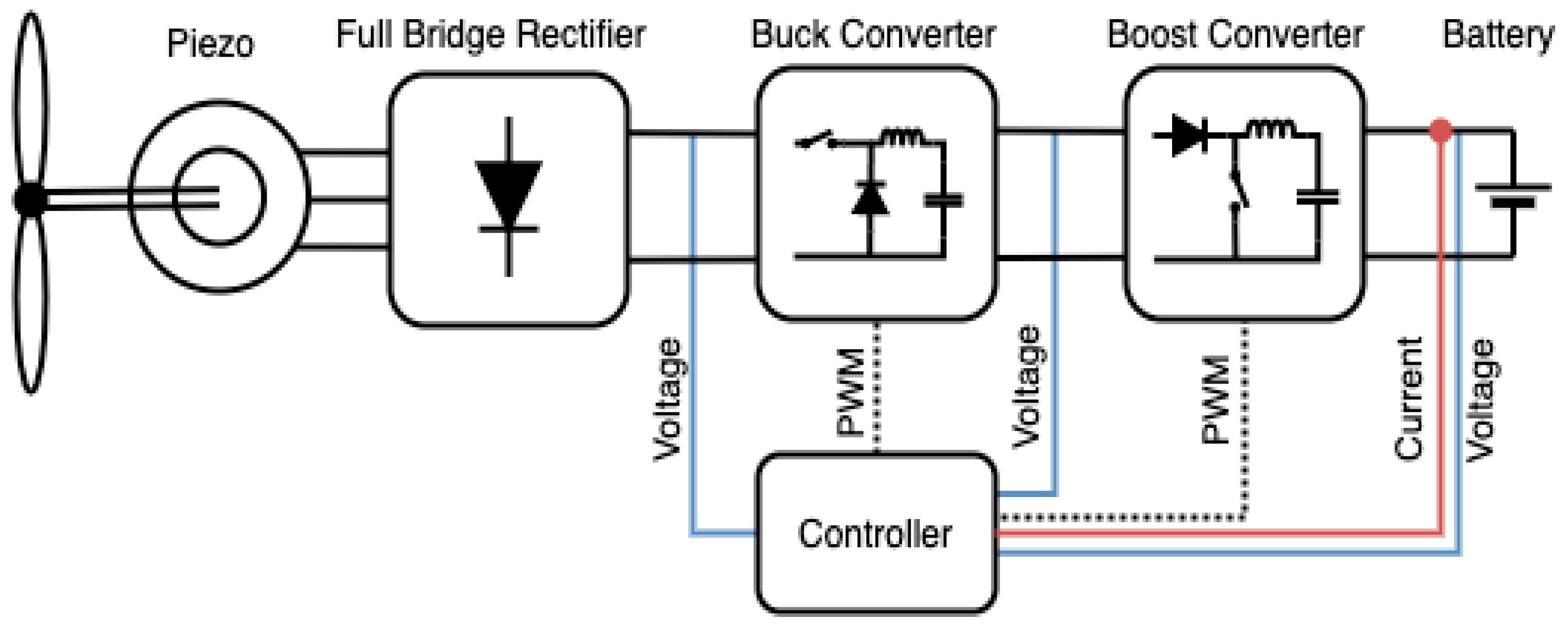
Figure 2.
PWEH unit with piezoelectric materials at the tip of the rotating parts.
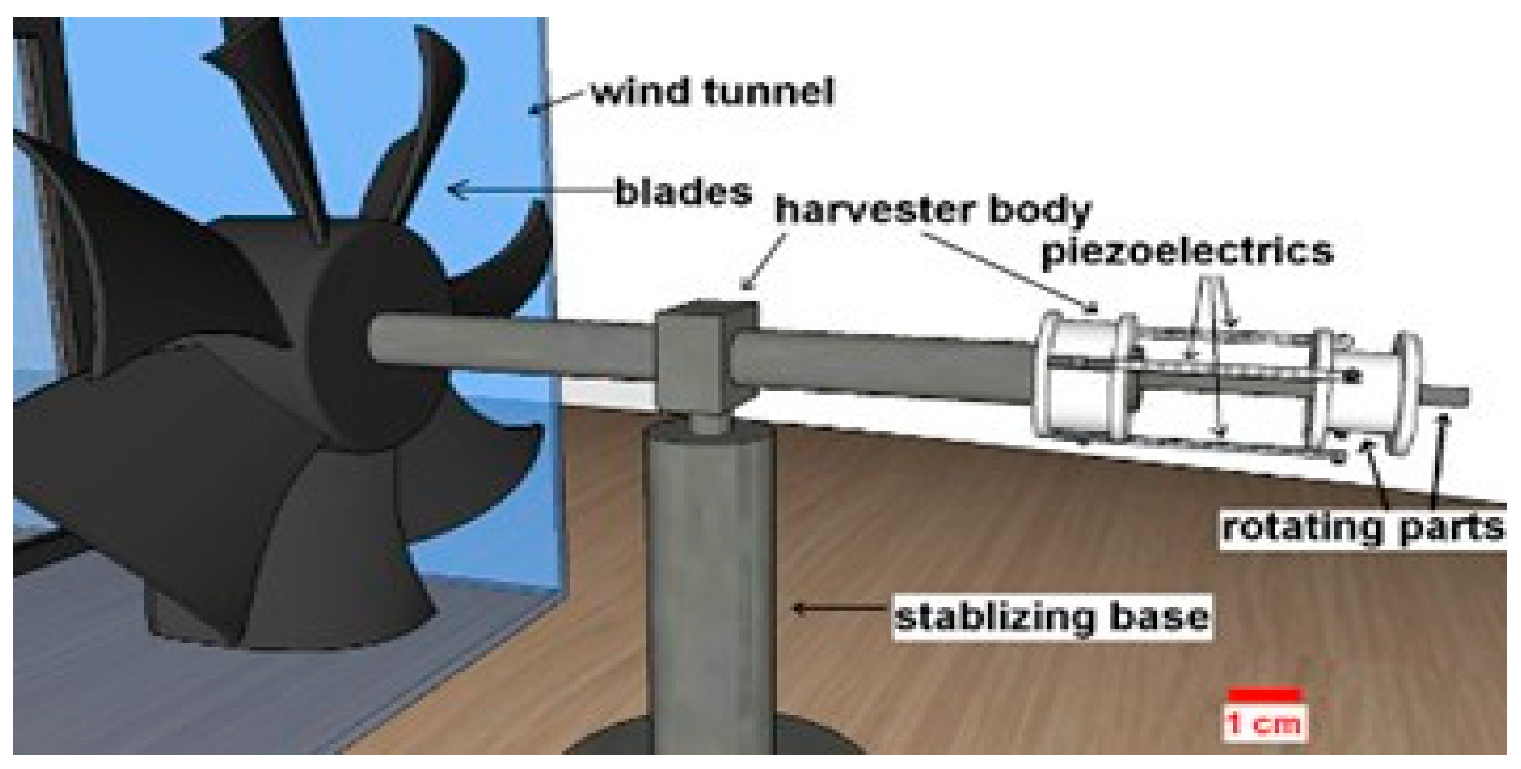
Figure 3.
General circuit diagram of the combination of PWEH and ESU.
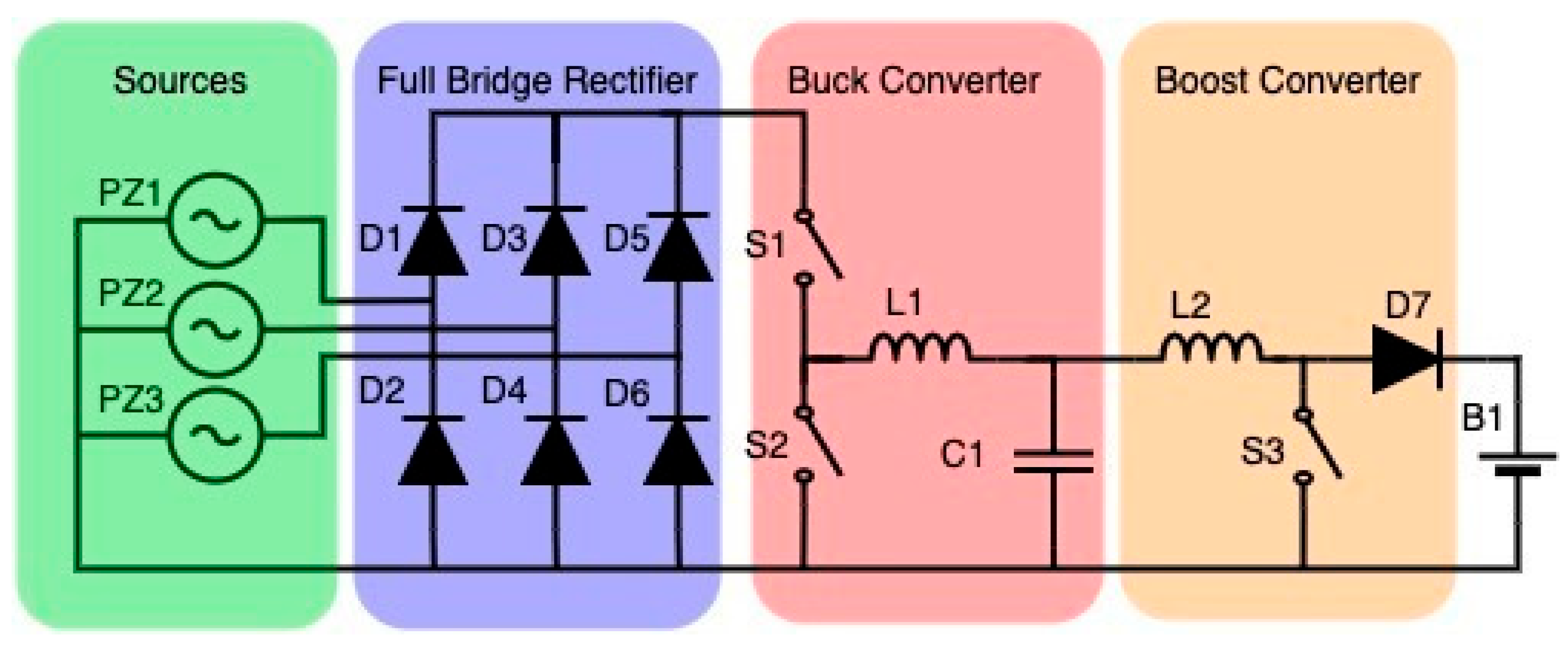
Figure 4.
General control structure of the proposed system.
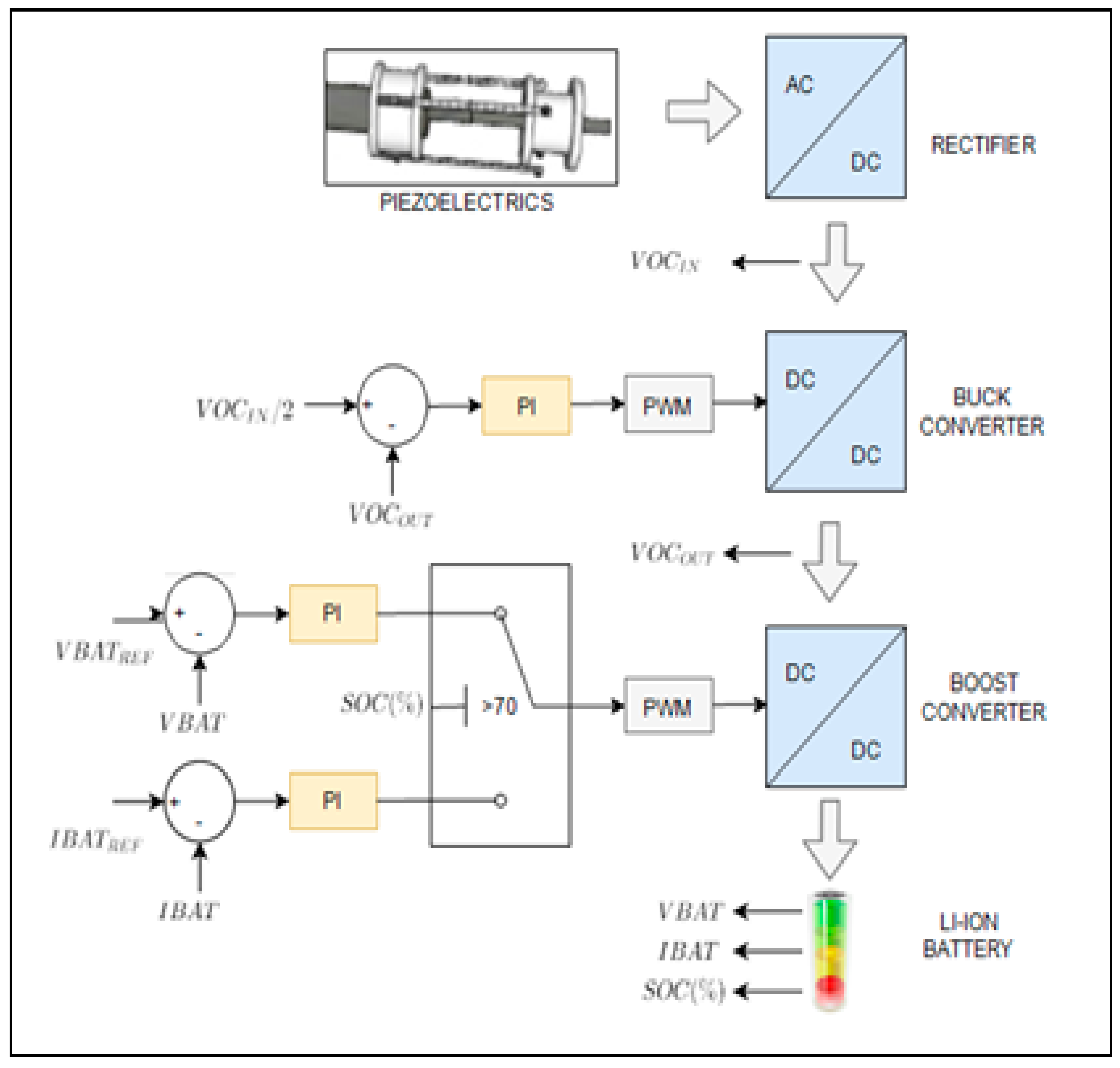
Figure 5.
Real waveforms of piezoelectric layers: a) wind tunnel speeds at 2.7 m/s, b) 3.5 m/s, c) 6.1 m/s.
Figure 5.
Real waveforms of piezoelectric layers: a) wind tunnel speeds at 2.7 m/s, b) 3.5 m/s, c) 6.1 m/s.
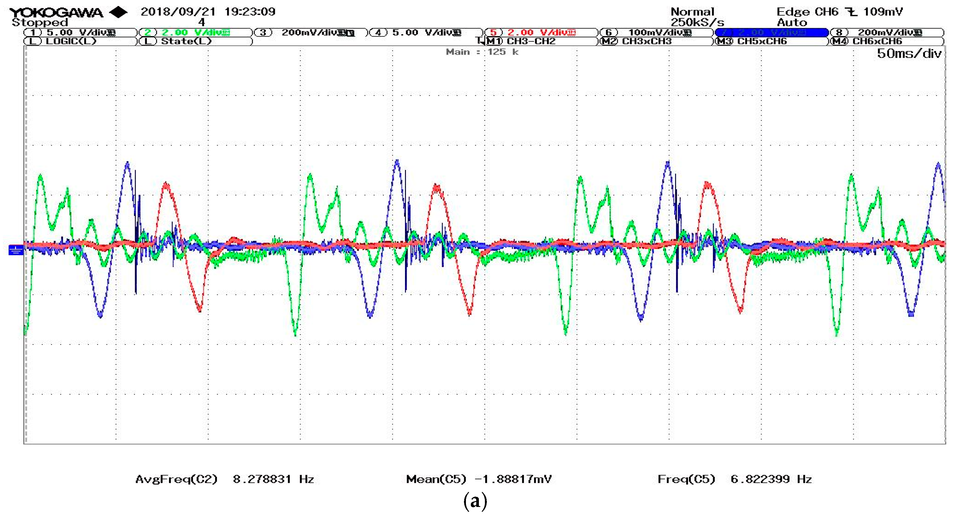
Figure 6.
Waveforms from DAQ card for MatLab process, (wind speeds at 3.5 m/s).
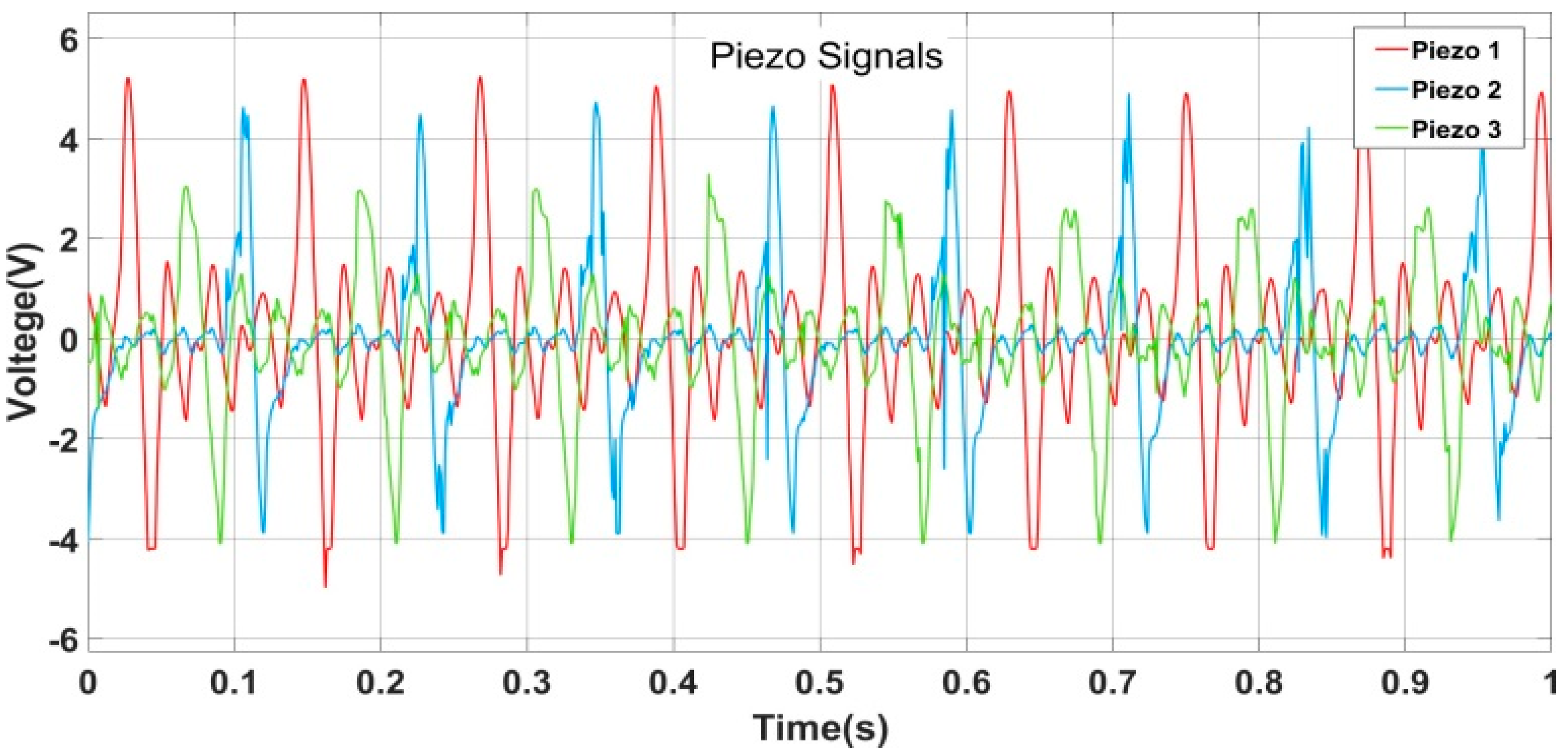
Figure 7.
Real piezo output signals.
Disclaimer/Publisher’s Note: The statements, opinions and data contained in all publications are solely those of the individual author(s) and contributor(s) and not of MDPI and/or the editor(s). MDPI and/or the editor(s) disclaim responsibility for any injury to people or property resulting from any ideas, methods, instructions or products referred to in the content. |
© 2025 by the authors. Licensee MDPI, Basel, Switzerland. This article is an open access article distributed under the terms and conditions of the Creative Commons Attribution (CC BY) license (http://creativecommons.org/licenses/by/4.0/).
Copyright: This open access article is published under a Creative Commons CC BY 4.0 license, which permit the free download, distribution, and reuse, provided that the author and preprint are cited in any reuse.


