Submitted:
07 September 2025
Posted:
09 September 2025
You are already at the latest version
Abstract
The increasing integration of photovoltaic (PV) power systems poses challenges for nighttime voltage regulation, as long high-voltage (HV) and ultra-high-voltage (UHV) underground cables generate capacitive reactive power that elevates grid voltage. Conventional compensators, based on passive inductors and capacitors, are bulky, costly, and inflexible, making them unsuitable for existing substations. This study proposes an optimization-based strategy that leverages the existing inverter infrastructure of PV plants to provide nighttime reactive power compensation without additional hardware. A genetic algorithm (GA) determines the optimal number and spatial deployment of inverters to minimize line losses. Field validation at a 120 MW PV plant with 1,292 inverters shows that the strategy reduces reverse reactive power from 0.84 MVAr to 0.00214 MVAr and line losses from 1.8235 kW to 0.386 kW using only 55 inverters, achieving near-zero additional capital expenditure (CAPEX). The method enhances voltage stability and system efficiency while reducing investment and maintenance costs.
Keywords:
photovoltaic (PV)
; reactive power compensation
; nighttime operation mode
; voltage stability
; inverter control
; genetic algorithm (GA)
1. Introduction
The rapid development and transformation of green energy have significantly changed its energy structure and usage [1,2]. Recently, utility-scale PV systems have been deployed in remote regions to meet the growing energy demands. When PV power plants do not operate at night, reactive power is generated, which causes instability in network voltage. An insufficient reactive power causes the voltage to drop, whereas an excessive reactive power increases the system voltage to excessively high levels. To stabilize the network voltage, reactive power must be controlled by considering the network power demand.
Various voltage regulation devices, such as constant power controllers, voltage regulators, and energy storage devices, have been employed to compensate for reactive power in PV power plants. In addition to these devices, a continuous power control method has been employed to reduce the power output of power plants [3]. Energy storage devices are also employed to suppress network voltage fluctuations and reactive power generation; however, they incur additional investment costs [4]. Static and dynamic virtual compensation methods have been developed to enhance the network voltage stability. However, large-scale applications are necessary while they require considerable investment, too [5]. According to the ref. [6], when the penetration level of PV systems reaches approximately 30% of the local load, it becomes difficult to maintain the voltage within acceptable limits without implementing a reactive power control via inverters. This threshold is consistent with the voltage regulation requirements specified in IEEE Std 1547™-2018 [7], which mandates that distributed energy resources (DERs) must provide voltage support functions to ensure grid stability. This finding underscores the importance of inverter-based voltage regulation in environments with a high PV penetration. Although traditional reactive power compensation devices, such as capacitor banks, are still widely used, their large physical footprint and complex installation render them unsuitable for deployment in existing substations. By contrast, utilizing existing PV plant inverters to provide nighttime reactive power support offers a more flexible and cost-effective alternative.
During the power generation process, inverters inherently generate reactive power; thus, PV power plants must participate in reactive power compensation during active generation. However, when reactive power support is mandated during non-generating periods, it is necessary to consider how to economically dispatch inverters within PV plants to stabilize the voltage without incurring additional installation costs.
In recent years, the concept of utilizing photovoltaic systems as static synchronous compensators, commonly referred to as PV-STATCOM, has been introduced to enhance voltage stability and provide reactive power support during both generating and non-generating periods [8]. Moreover, earlier studies also demonstrated the capability of PV inverters to perform local power factor correction, further confirming their potential for reactive support [9].
In large-scale PV power plants, the number of inverters typically exceeds several thousand, and the length of high-voltage (HV) and ultra-high-voltage (UHV) underground cables span several tens of kilometers. The reactive power generated by these systems is predominantly capacitive. However, the reactive power capacity of PV inverters is constrained by the impedance of the transmission lines [10,11]. Therefore, when dispatching inverters for reactive power support, it is essential to consider strategies to minimize line losses simultaneously. This constituted one of the primary objectives of this study.
Significant progress has been made in nighttime reactive power compensation for PV systems. Huque et al. investigated the feasibility of utilizing PV inverters to provide reactive power during the nighttime to reduce grid operating costs. This method has both economic and technical advantages [12]. In addition, A. F. Minai et al. proposed a reactive power optimization strategy for power systems using a GA, specifically targeting systems such as PV power plants. The method effectively improved the bus voltage profiles and ensured compliance with voltage standards [13]. However, these studies primarily focused on theoretical analysis and simulation-based validation and lacked field-test data from large-scale PV plants. Further research is required to evaluate the effectiveness and reliability of these methods in real-world applications.
To address this issue, this study adopts a GA to optimize the reactive power output of a PV power plant and determine a dispatch strategy for inverter-based reactive power compensation. The GA offers excellent performance in solving large-scale optimization problems. It requires only a well-defined objective function without the need for gradient information, and is capable of handling both discrete and continuous variables simultaneously. Given that this study involves a mixed-variable optimization problem, determining the number of inverters to activate (integer variables) and their reactive power outputs (continuous variables), the GA provides high adaptability. To verify the effectiveness of the proposed method, a field test was conducted at a large-scale PV power plant with an installed capacity of 120 MW
2. Inverter-Based Reactive Power Control
The inverter converts the direct current (DC) supplied by the solar panels into alternating current (AC) for the power output. At night, the inverter’s nighttime reactive power compensation mode is activated. In this mode, inverters in the PV power plant remain connected to the utility grid on the AC side throughout the night and consume only a small amount of energy from the grid to power their internal components. This allows inverters to inject purely reactive power into the grid for voltage support. Figure 1 illustrates the circuit of the inverter operating in the nighttime mode.
Reactive power compensation is critical in power systems for regulating voltage levels, improving the power factor, and enhancing the overall system operating efficiency. Although reactive power compensation does not directly supply active power to the system, it plays a vital role in maintaining voltage stability and enabling the effective transmission of active power. Inverters compensate for the reactive power by leveraging their internal power electronic components and advanced control technologies. These technologies allow inverters to adjust the phase angle of the current flexibly, thereby enabling the absorption or injection of reactive power, as needed. The inverter process to compensate for reactive power is described as follows:
2.1. Operating Principle of the Inverter
The inverter primarily converts DC into AC. However, they can also control the phase angle, voltage magnitude, and frequency of AC output. The inverter can control the injection or absorption of reactive power by adjusting the phase angle between the output voltage and current.
2.2. Phase Angle Control Mechanism
In AC power systems, the total power consists of active and reactive components. The phase angle between the voltage and current determines the power distribution ratio. The reactive power corresponds to the orthogonal component and can be dynamically compensated for by controlling the phase angle of the current. The inverter regulates reactive power through the following mechanism:
- When the output current lags behind the voltage (phase angle close to +90°), the inverter behaves as an inductive load and absorbs reactive power, thereby suppressing overvoltage conditions;
- When the output current leads to a voltage (phase angle close to −90°), the inverter behaves as a capacitive load and injects reactive power, supporting low-voltage scenarios.
2.3. d-q Axis Decoupled Control Strategy
In this study, a standard d-q axis current control method was adopted. During nighttime operation, under the condition reactive power output is regulated by adjusting the component. The corresponding reactive power expression is given as
where
Reactive power output of inverter
Output voltage magnitude of inverter
q-axis current component
Maximum reactive power capability
Rated apparent power of the inverter
Active power output of inverter
Since during nighttime, the maximum available reactive power becomes:
2.4. Dispatch Logic and Constraint Modeling
The inverter can dynamically adjust its reactive power output in response to grid conditions such as voltage fluctuations or load variations. These adjustments are typically driven by voltage monitoring and control algorithms that leverage the fast-response capabilities of the inverter. This dynamic reactive power compensation plays a critical role in maintaining grid stability. In the GA optimization framework, the dispatch decision variable is defined as a binary vector.
Where indicates that inverter is activated to participate in reactive power dispatch. The algorithm determines the activation of each inverter based on the following three criteria:
- The total reactive power requirement derived from voltage sensitivity analysis;
- Line loss minimization based on the distance to the substation and cable impedance;
- The reactive power limit
of each inverter, as defined by manufacturer specifications.
2.5. Nighttime Operating Modes of Inverters
Various high-voltage underground cables of different sizes are used in large-scale photovoltaic (PV) power plants. At night, PV plants stop generating active power. While the reactive power absorbed by distribution transformers is usually minimal, it may still cause slight voltage deviations. The equation for the capacitive reactive power with respect to the line voltage and cable length is:
where
Capacitive reactive power (.
Line voltage (.
Angular frequency (.
Cable capacitance per unit length (.
Cable length (.
The 22.8 and 161 kV underground cables provided reactive power to the system. The influx of a large amount of reactive power during nighttime increases the system voltage, thereby affecting power quality. In severe cases, it triggers the operation of the overvoltage protection relays. To mitigate this issue, the selected inverters are switched to night-time reactive power absorption mode. However, when implementing this mode, it is necessary to consider the associated line losses and the impact of the distribution transformers.
3. GA for Reactive Power Optimization
A GA is a learning algorithm that imitates biological processes. During the natural evolution of organisms, a group of individuals forms a generation (population) that reproduces individuals to adapt to the environment and survive with a higher probability.
The GA process is illustrated in Figure 2 and consists of the following steps.
- The total reactive power requirement is first obtained via voltage sensitivity analysis;
- Fitness Evaluation: The fitness of each candidate solution is calculated based on the objective function and constraint conditions;
- Selection: Based on fitness, a subset of better candidate solutions is selected as the parent candidate for the next generation;
- Crossover: The selected parent candidates are combined to generate new candidate solutions;
- Mutation: Some candidate solutions are randomly modified to increase the diversity of solutions;
- Population Update: The old population is replaced with new candidate solutions, and the process is repeated;
- Termination Condition: The genetic algorithm terminates when a predefined stopping criterion is met (e.g., the maximum number of iterations or an adequately optimal solution is found).
In this study, we determined the optimal number of inverters to be dispatched, and identified the specific regions in which the inverters were involved in reactive power compensation. To achieve this, we defined the objective function as follows:
Constraints are defined as.
where
Reactive power supplied by underground cables.
Reactive power absorbed by underground cables and distribution transformers during nighttime operation.
Total reactive power absorbed by inverters during nighttime operation.
Line losses.
Number of inverters participating in reactive power compensation.
, are the weights
(in this study).
is the amount of reactive power compensated for by inverter i.
In this study, the Genetic Algorithm (GA) was selected as the primary optimization method owing to the following advantages:
- The total reactive power requirement derived from voltage sensitivity analysis;
The GA utilizes a population-based parallel search combined with stochastic mutation mechanisms, which enables it to effectively escape local optima. This characteristic makes it particularly well suited for addressing nonlinear and high-dimensional optimization problems, such as the complex combinatorial scheduling of inverter quantities and spatial deployment considered in this research.
- Compatibility with mixed-variable problems;
The GA requires only the evaluation of the objective function and does not rely on gradient information, allowing it to handle both discrete and continuous variables. This is especially advantageous for current applications that involve joint optimization of discrete inverter activation decisions and continuous reactive power outputs.
- High degree of parallelizability.
The independent evaluation of each chromosome in the population enables efficient parallel computation, making the GA particularly applicable to large-scale systems such as the 1,292-inverter PV plant studied in this work.
Moreover, although machine learning techniques such as reinforcement learning and deep neural networks have demonstrated strong performance in real-time control and highly uncertain environments, they typically require extensive offline training with large volumes of historical data. As this study focuses on the static dispatch problem, such methods are not considered suitable.
4. Field Experiments and Result
A field experiment was conducted at a fully constructed and operational 120 MW photovoltaic (PV) power plant. The plant consists of 24 unit step-up substations and adopts a two-stage voltage transformation process, where the inverter output voltage is boosted from 0.38 kV to 161 kV. The internal distribution system includes feeders and branch cables extending over 3 km, and the maximum capacity of the distribution transformers is 6,500 kVA. In this study, a GA was employed to determine the optimal number and spatial allocation of inverters to be activated during nighttime operation, aiming to absorb the reactive power fed back into the grid while simultaneously minimizing line losses.
4.1. Parameter Settings
This study was conducted in a large-scale PV power plant equipped with 1,292 inverters. GA was applied to determine the optimal placement of inverters for reactive power compensation and to calculate the number of inverters that needed to be activated at night to offset the reactive power fed back into the grid. The optimization process was implemented using MATLAB’s built-in GA function. The corresponding parameter settings were as follows:
- Initial population range: During nighttime operation, the PV plant injected 2.8 MVAr of reactive power into the grid. Each inverter has a rated output of approximately 50 kVAr, which corresponds to approximately 56 inverters. To ensure sufficient search diversity while accommodating possible variations in the inverter output during operation, and to avoid excessively large initial values that could hinder the convergence of the algorithm, the initial population range was set between 30 and 65;
- Population size: To avoid falling into local optima, provide a broader search space, and increase the probability of finding the global optimum, the population size was set to 1000;
- Crossover fraction: Since the locations of inverters to be activated in nighttime reactive power compensation were not easily identified, the crossover fraction of 0.9 was chosen to accelerate convergence and quickly identify the optimal solution;
- Mutation rate: The mutation step size is adaptively adjusted according to the population performance and constraint conditions, ensuring that mutated individuals remain within the feasible solution space;
- Fitness evaluation: The fitness value of each candidate solution is calculated using the objective function. A lower fitness value indicates a better solution; therefore, it was calculated to determine the minimum number of inverters and minimize line losses;
- Constraint tolerance: To solve problems involving nonlinear constraints, the allowable tolerance was set as 1×10⁻⁵ ;
- Maximum generation: Because the objective function is nonlinear, the maximum generation value was defined as 400 to ensure a sufficient exploration time for identifying the optimal solution.
4.2. Power Plant Equipment and Nighttime Reverse Reactive Power Output
Figure 3 shows a single-line diagram of the monitored large-scale PV power plant. As shown, all critical nodes from the DC side to the AC side are equipped with SCADA systems to enable real-time monitoring and data logging. The ultrahigh-voltage underground cables used in the PV plant were rated 161 kV × 2000 mm², whereas the medium-voltage underground cables were rated 25 kV × 250 mm² and 25 kV × 60 mm². The plant is equipped with 24 unit step-up substations, which are primarily used to boost the inverter output voltage from 0.38 kV to 22.8 kV. The impedance values of the associated equipment and distribution transformers (DTR) are listed in Table 1. Figure 4 shows the active and reactive power output of the PV power plant at the point of common coupling (PCC). All the data presented in the figure were obtained from the regional power dispatch center of the Taiwan Power Company. The symbol “—” indicates power flowing into the grid. During the non-generating period (from 18:00 to 6:00), the PV plant injected 2.8 MVAr of reactive power into the grid, which either violated the grid code requirements or raised concerns regarding the triggering of overvoltage protection mechanisms.
4.3. Field Measurement Analysis and Discussion
We compared the results obtained by randomly selecting the inverter locations with those optimized using the GA. Figure 5 shows the results during the non-generating period (18:00 to 06:00), where 68 inverters were randomly activated at DTR No.7 in the night-time reactive power absorption mode. The system was injected with an excessive 0.84 MVAr of reactive power (causing a shift from capacitive to inductive behavior), and line losses amounted to 1.8235 kW.
As shown in Figure 6, the GA reached convergence by the 6th generation, demonstrating that the optimization process was both stable and efficient. Therefore, the subsequent results were obtained using the solutions after convergence, ensuring reliability in the inverter allocation strategy. The objective function value is 1.26104 k, which is significantly lower than that of the single inverter when the constraint tolerance is set to 0.00001. To enhance the convergence accuracy, the maximum number of generations was increased to 400, and the population size was set to 1000. Figure 7 illustrates the optimal number and locations of inverters determined by the GA:11 inverters at DTR No.2, 14 at DTR No.4, and 30 at DTR No.5, for a total of 55 inverters.
The GA selected DTR No.2, No.4, and No.5 as the optimal inverter groups, which is consistent with the electrical characteristics of the system. These transformers are relatively close to the PCC and have smaller line impedances, so reactive power injected at these points directly supports the bus voltage and reduces unnecessary reactive flows along the feeders, thereby lowering line losses. Because the compensation efficiency is higher at these locations, fewer inverters need to be activated to meet the nighttime reactive power requirements. This explains why the GA converged to these specific DTRs rather than to other locations. The reactive power fed back to the grid at the point of interconnection was reduced to the ideal value of 0.00214 MVAr (Figure 8).
5. Conclusion
Conventional reactive power compensators are constructed using passive components such as inductors and capacitors, which are typically large and require substantial installation space. These devices are generally installed on the high-voltage or ultrahigh-voltage sides of a system, necessitating the use of additional circuit-breakers. For existing shared booster stations that are already in operation, limited available space is a significant challenge for the installation of such devices. Furthermore, traditional reactive power compensators often suffer from overcompensation or undercompensation, making it difficult to achieve precise reactive power control.
In this study, GA was applied to determine the optimal number and placement of inverters. A total of 55 inverters were activated in the nighttime reactive power compensation mode at the PV power plant in which the experiment was conducted. Using this approach, the reactive power fed back into the grid was significantly reduced to 0.00214 MVAr and the line losses decreased from 1.8235 kW to 0.386 kW. A comparison of the system performance before and after the optimization is shown in Figure 9.
The developed method was successfully implemented in a fully operational, large-scale PV power plant. The results demonstrated that the GA-based method effectively reduced the number of inverters required and minimized line losses, thereby significantly lowering the operation and maintenance costs of the PV power plant while extending the service life of the inverters. The proposed strategy demonstrates strong applicability to the existing PV infrastructure and offers a cost-effective solution for reactive power control.
Table 2 provides a comparison between this study and recent literature related to nighttime reactive power regulation in PV systems. Unlike other studies that primarily focus on simulation-based analysis, this work is the only one validated using real-world data from a 120 MW PV power plant, demonstrating its higher practical applicability. Moreover, while previous research has largely concentrated on improving voltage profiles, the present study simultaneously optimizes both the selection and spatial allocation of inverters, aiming to minimize the reactive power backfeed and line losses. These objectives were successfully achieved and verified in an actual field.
In Table 3, it is summarized that the proposed method requires almost no additional investment compared with SVC and STATCOM solutions, while still providing equivalent reactive power support capability.
Future research will focus on integrating machine learning with inverter anomaly detection. In terms of machine learning, a Digital Twin (DT) framework will be employed to enable real-time monitoring and dispatch of inverters, thereby realizing an economic dispatch model. For anomaly detection, techniques such as Principal Component Analysis (PCA) and one-class Support Vector Machines (OCSVM) can be applied to identify inverters with reduced generation efficiency. Subsequently, multi-objective optimization methods may be employed to further enhance overall system performance and power generation efficiency.
Acknowledgments
The authors would like to thank Fimer S.p.A. for providing the inverter technical documentation and Taiwan Power Company for supplying SCADA data used in this study.
References
- Gayatri, M.T.L.; Parimi, A.M.; Kumar, A.V.P. A review of reactive power compensation techniques in microgrids. Renewable Sustain. Energy Rev. 2018, 81, 1030–1036. [Google Scholar] [CrossRef]
- Liu, Z.; Hao, H.; Cheng, X.; Zhao, F. Policy impacts on China’s energy transition. Energy Policy 2018, 115, 92–100. [Google Scholar] [CrossRef]
- Phochai, O.; Ongsakul, W.; Mitra, J. Voltage control strategies for grid-connected solar PV systems. In Proceedings of the 2014 International Conference and Utility Exhibition on Green Energy for Sustainable Development (ICUE), Pattaya, Thailand, 19–21 March 2014; IEEE: Piscataway, NJ, USA, 2014; pp. 1–7. [Google Scholar] [CrossRef]
- Yi, Y.; Jiongcong, C.; Nanhua, Y.; Xiaoping, Z.; Xudong, S. Coordinate voltage control in active distribution network. In Proceedings of the 2014 International Conference on Power System Technology (POWERCON), Chengdu, China, 20–22 October 2014; IEEE: Piscataway, NJ, USA, 2014; pp. 2668–2673. [Google Scholar] [CrossRef]
- Varma, V.; Nagarajan, S.T. PV solar farm as statcom for voltage regulation. In Proceedings of the 2016 IEEE 7th Power India International Conference (PIICON), Bikaner, India, 25–27 November 2016; IEEE: Piscataway, NJ, USA, 2016; pp. 1–5. [Google Scholar] [CrossRef]
- Eichkoff, H.S.; Bernardon, D.P.; de Mello, A.P.C.; da Silva, G.S.; Machiavelli, J.A. Local volt/var control in distribution networks with photovoltaic generators. In Proceedings of the 2019 IEEE PES Innovative Smart Grid Technologies Conference—Latin America (ISGT Latin America), Gramado, Brazil, 15–18 September 2019; IEEE: Piscataway, NJ, USA, 2019; pp. 1–6. [Google Scholar] [CrossRef]
- IEEE Standard Association. IEEE Standard for Interconnection and Interoperability of Distributed Energy Resources with Associated Electric Power Systems Interfaces. IEEE Std 1547™-2018 (Revision of IEEE Std 1547-2003); IEEE: Piscataway, NJ, USA, 2018; pp. 1–138. [Google Scholar] [CrossRef]
- Kumar, N.; Buwa, O.N.; Thakre, M.P. Virtual synchronous machine based PV-STATCOM controller. In Proceedings of the 2020 IEEE First International Conference on Smart Technologies for Power, Energy and Control (STPEC), Nagpur, India, 25–26 September 2020; IEEE: Piscataway, NJ, USA, 2020; pp. 1–6. [Google Scholar] [CrossRef]
- Peng, W.; Baghzouz, Y.; Haddad, S. Local load power factor correction by grid-interactive PV inverters. In Proceedings of the 2013 IEEE Grenoble PowerTech Conference (PTC), Grenoble, France, 16–20 June 2013; IEEE: Piscataway, NJ, USA, 2013; pp. 1–6. [Google Scholar] [CrossRef]
- Kulkarni, S.N.; Shingare, P. A review on smart grid architecture and implementation challenges. In Proceedings of the 2016 International Conference on Electrical, Electronics, and Optimization Techniques (ICEEOT), Chennai, India, 3–5 March 2016; IEEE: Piscataway, NJ, USA, 2016; pp. 3285–3290. [Google Scholar] [CrossRef]
- Dai, J.; Tang, Y.; Xu, Y.; Yan, Q. Reactive power optimization coordinated control strategy of the large-scale PV power station. In Proceedings of the 2018 International Conference on Power System Technology (POWERCON), Guangzhou, China, 6–8 November 2018; IEEE: Piscataway, NJ, USA, 2018; pp. 1632–1637. [Google Scholar] [CrossRef]
- Huque, A.; Magerko, A.; Brewser, C.; Key, T. Nighttime reactive power support from solar PV inverters. In Proceedings of the 22nd Wind and Solar Integration Workshop (WIW 2023), Copenhagen, Denmark, 25–27 September 2023; IEEE: Piscataway, NJ, USA, 2023; pp. 584–588. [Google Scholar] [CrossRef]
- Minai, A.F.; Khan, A.A.; Siddiqui, M.A.; Bakhsh, F.I.; Hussain, M.A.; Pachauri, R.K. Genetic algorithm based SPV system with cascaded H-bridge multilevel inverter. In Proceedings of the 2023 International Conference on Power, Instrumentation, Aligarh, India, 24–26 February 2023, Energy and Control (PIECON); IEEE: Piscataway, NJ, USA, 2023; pp. 1–6. [Google Scholar] [CrossRef]
Figure 1.
(a) Equivalent diagram of a single inverter, (b) inverter absorbing reactive power, and (c) inverter supplying reactive power. (Data source: Fimer).
Figure 1.
(a) Equivalent diagram of a single inverter, (b) inverter absorbing reactive power, and (c) inverter supplying reactive power. (Data source: Fimer).
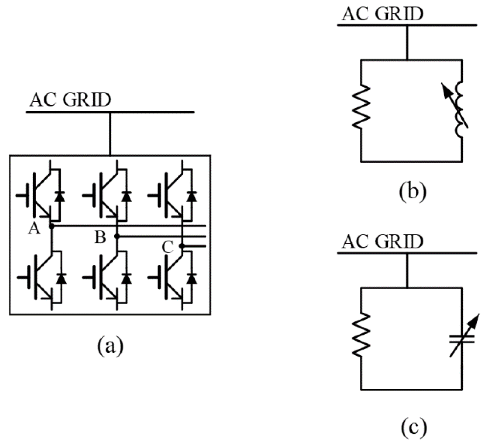
Figure 2.
Process of GA.
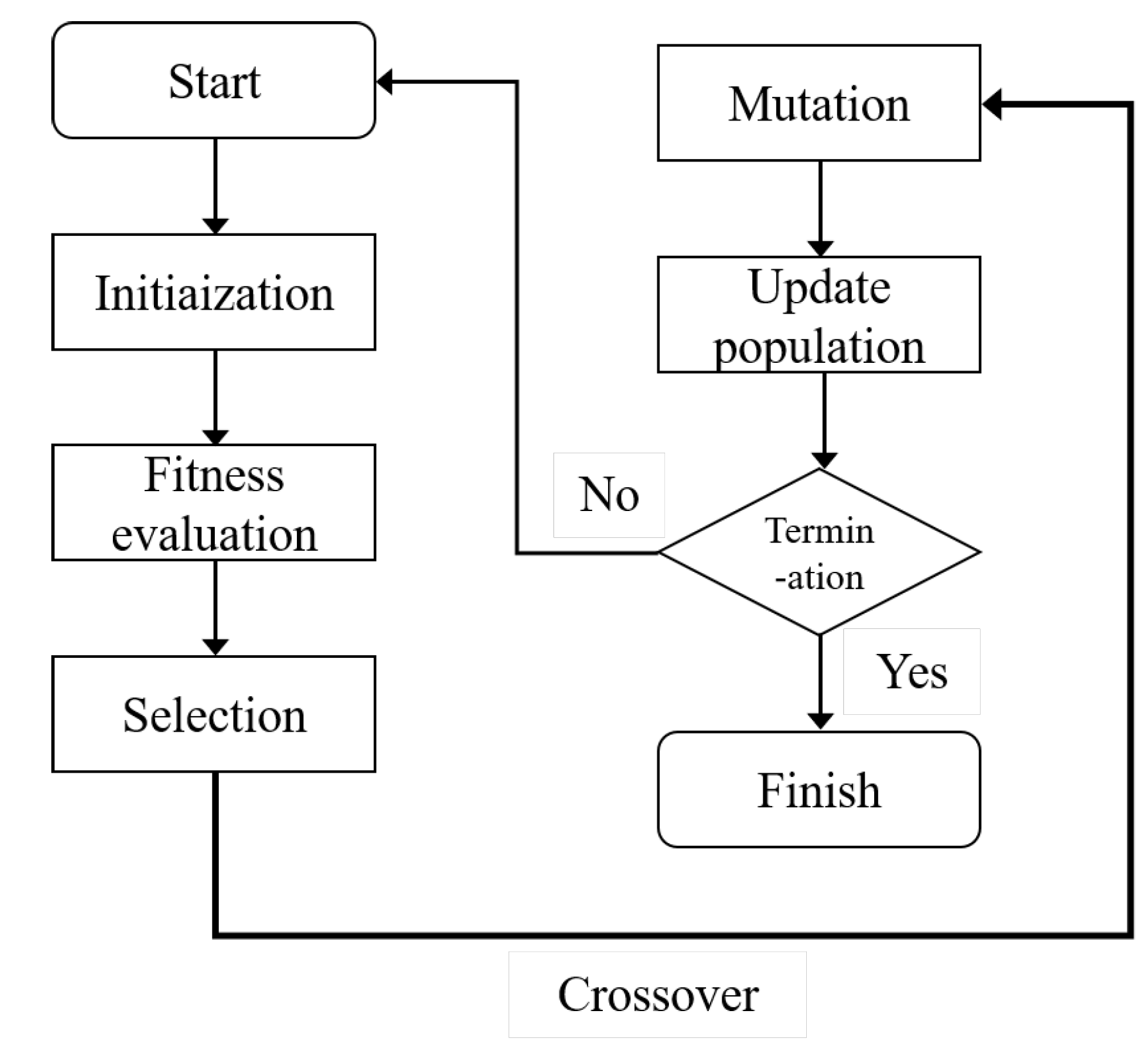
Figure 3.
Single-line diagram of PV plant.
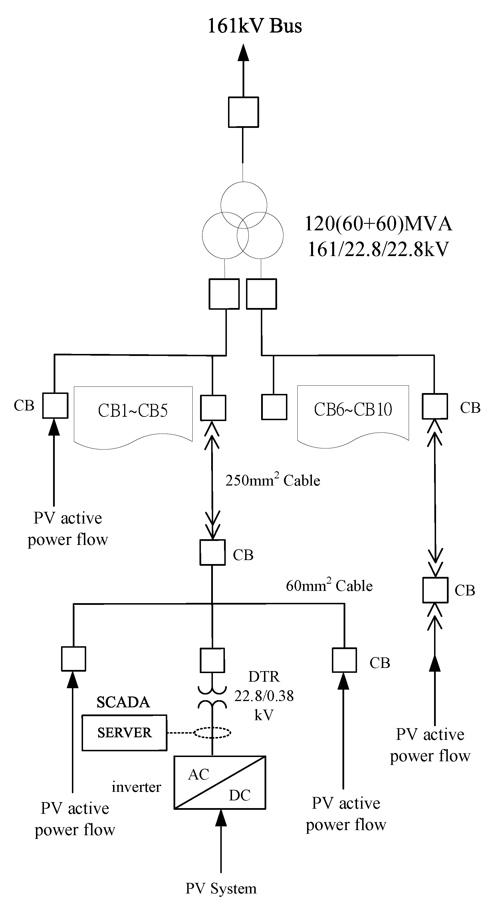
Figure 4.
Power flow curve of the solar power plant before improvement. (Data source: Taipower SCADA).
Figure 4.
Power flow curve of the solar power plant before improvement. (Data source: Taipower SCADA).
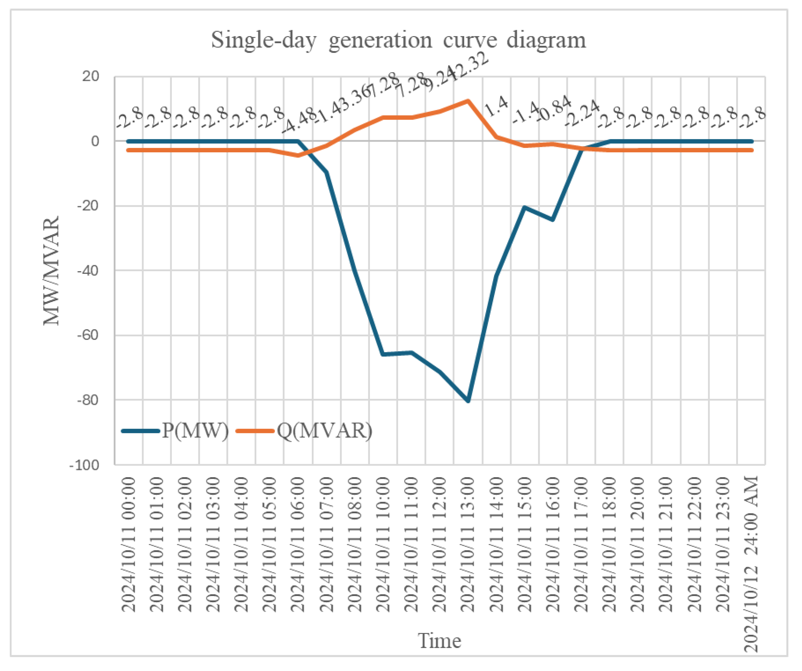
Figure 5.
Power flow curve for a non-optimized (random) placement without GA. (Data source: Taipower SCADA).
Figure 5.
Power flow curve for a non-optimized (random) placement without GA. (Data source: Taipower SCADA).
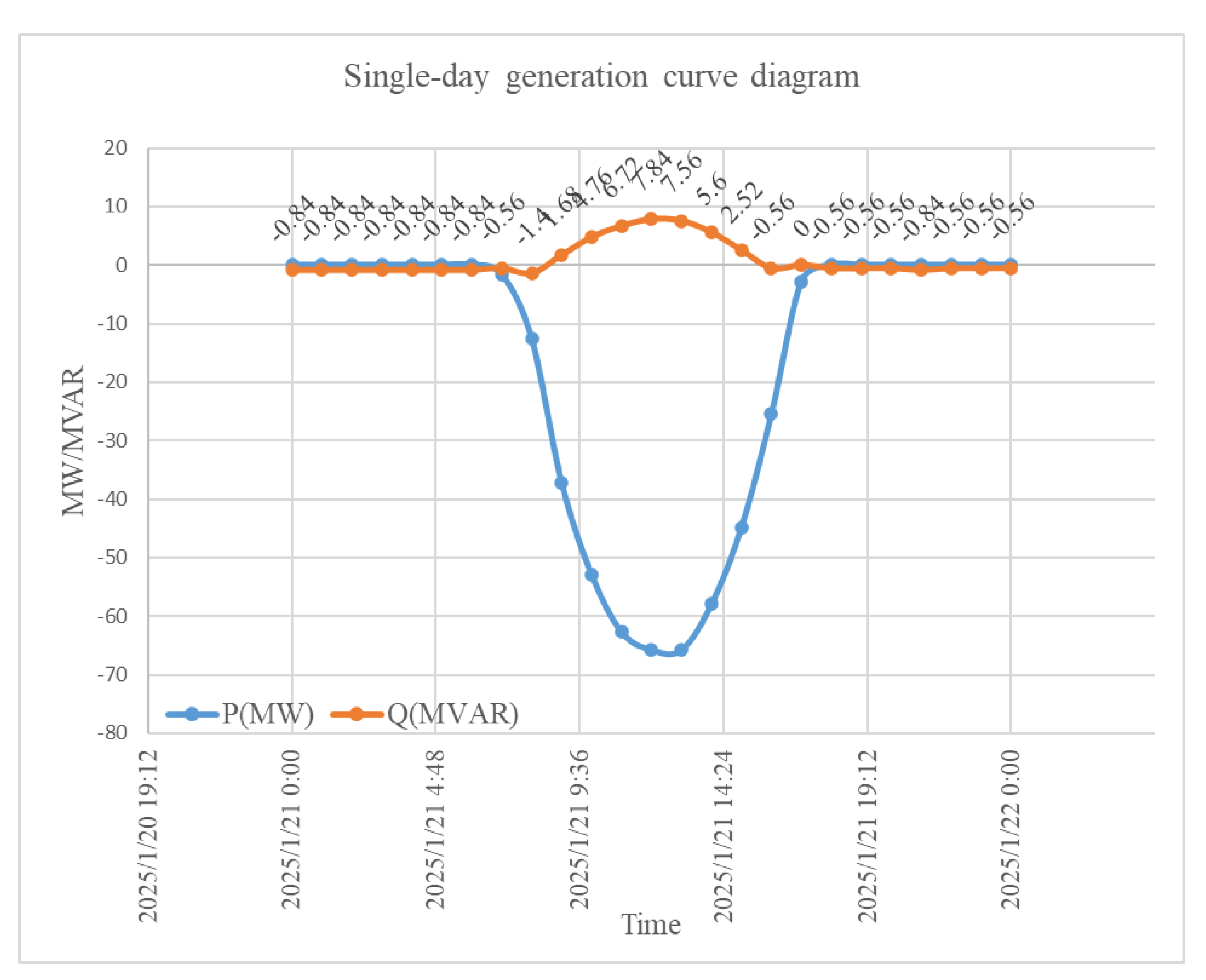
Figure 6.
GA convergence curve, showing that the algorithm converged within the 6th generation, which indicates stability of the optimization process.
Figure 6.
GA convergence curve, showing that the algorithm converged within the 6th generation, which indicates stability of the optimization process.
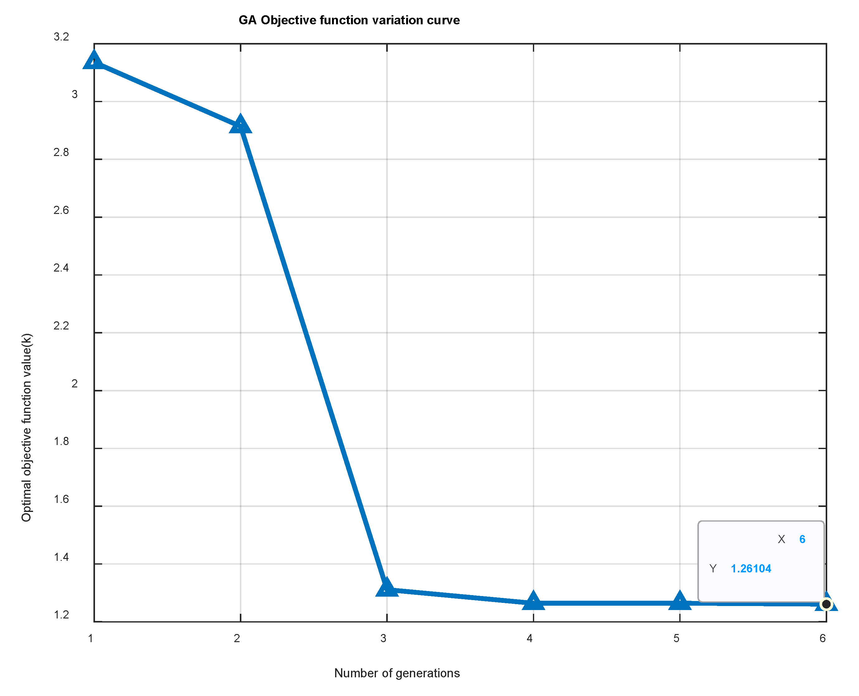
Figure 7.
Optimal inverter placement identified by GA. The solution selects DTR No.2, No.4, and No.5, which are closer to the PCC with lower line impedances, enabling effective reactive power support with fewer inverters.
Figure 7.
Optimal inverter placement identified by GA. The solution selects DTR No.2, No.4, and No.5, which are closer to the PCC with lower line impedances, enabling effective reactive power support with fewer inverters.
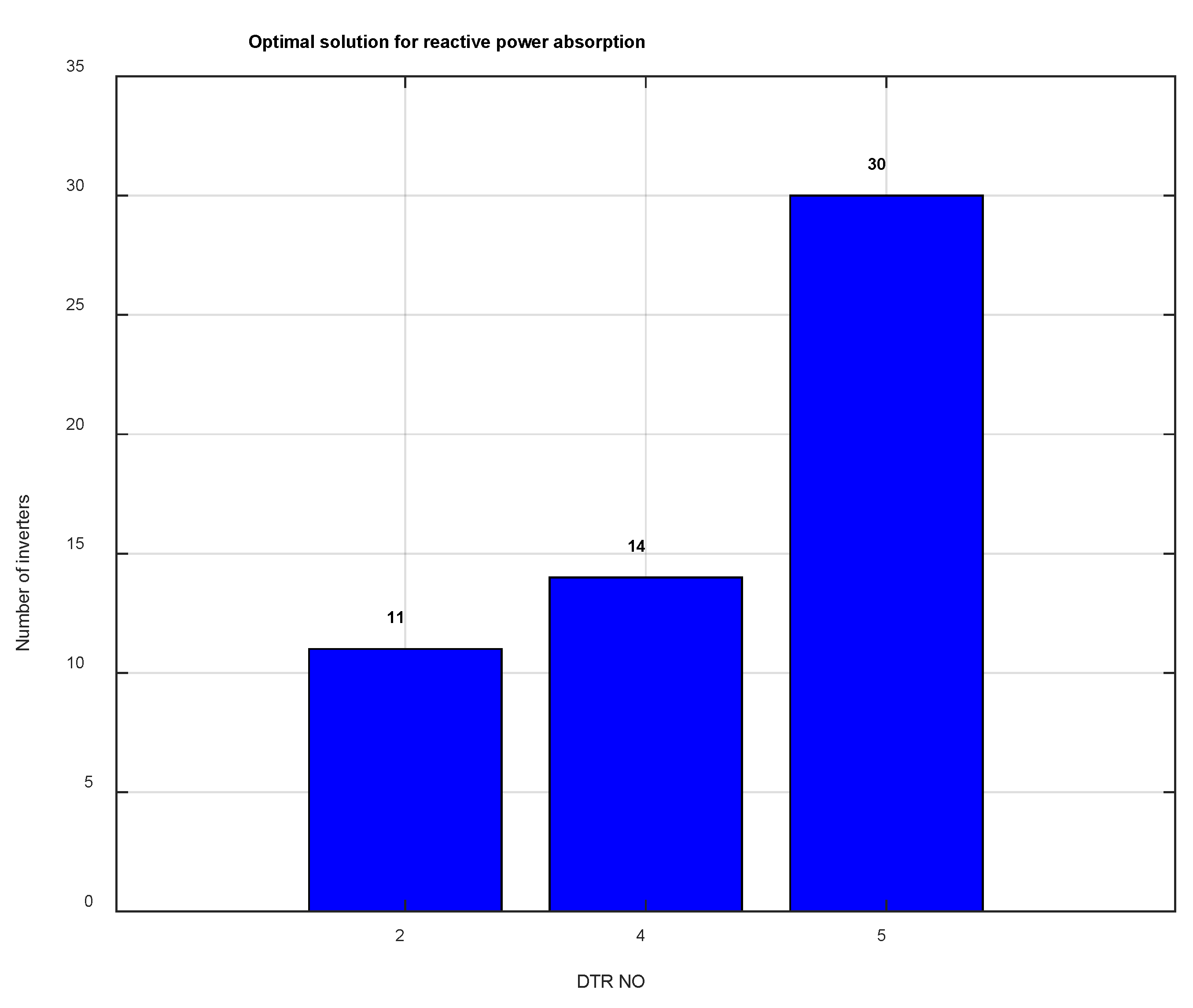
Figure 8.
Reactive power flow at PCC after GA optimization, demonstrating suppression to 0.00214 MVAr. (Data source: Taipower SCADA.).
Figure 8.
Reactive power flow at PCC after GA optimization, demonstrating suppression to 0.00214 MVAr. (Data source: Taipower SCADA.).
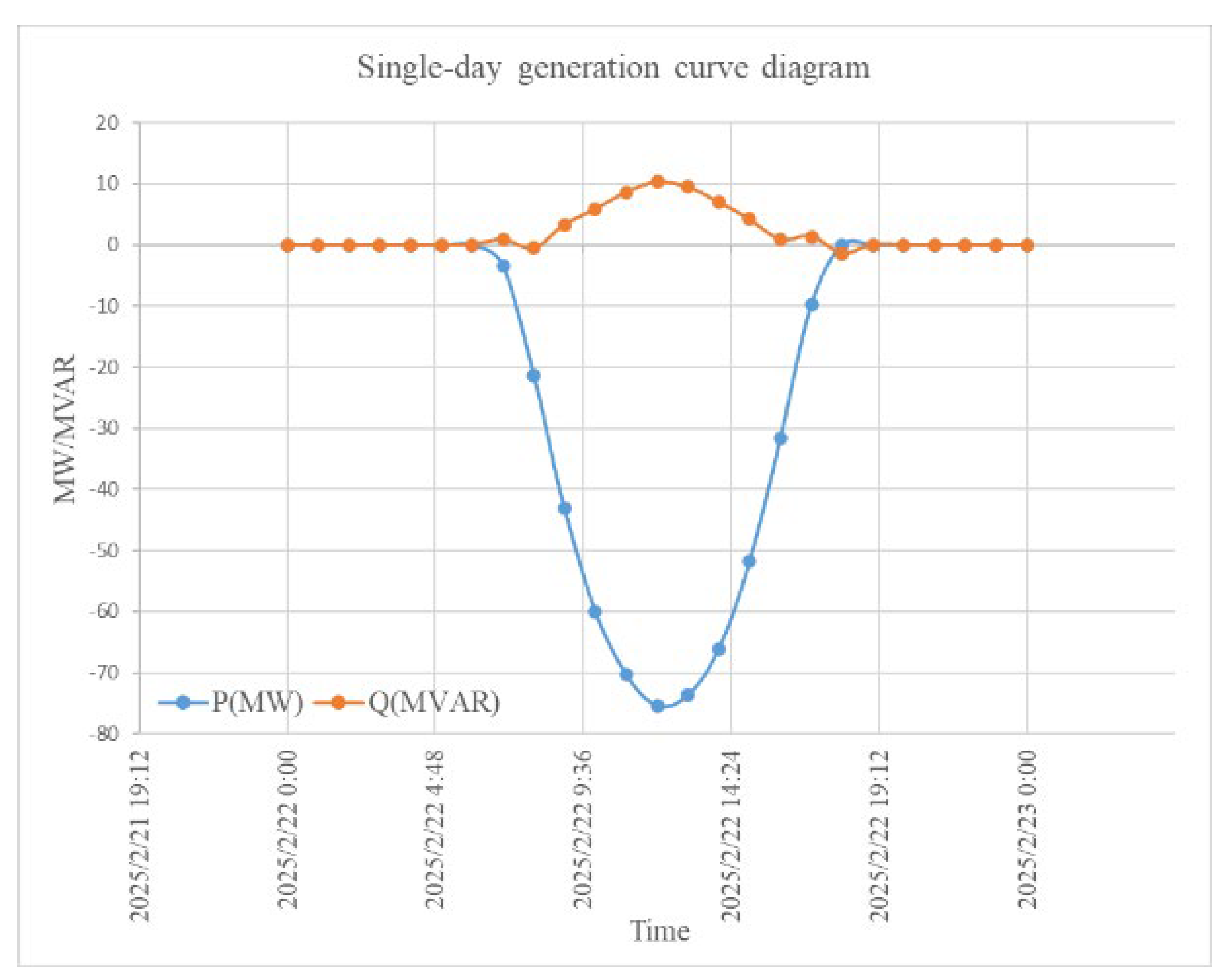
Figure 9.
System Performance Before and After GA Optimization.

Table 1.
Impedance characteristics of transformers and cables.
 |
Table 2.
Comparative Summary of Research Results on Nighttime Reactive Power Control in PV Systems.
 |
Table 3.
Comparison of Nighttime Reactive Power Compensation Approaches.
 |
Disclaimer/Publisher’s Note: The statements, opinions and data contained in all publications are solely those of the individual author(s) and contributor(s) and not of MDPI and/or the editor(s). MDPI and/or the editor(s) disclaim responsibility for any injury to people or property resulting from any ideas, methods, instructions or products referred to in the content. |
© 2025 by the authors. Licensee MDPI, Basel, Switzerland. This article is an open access article distributed under the terms and conditions of the Creative Commons Attribution (CC BY) license (http://creativecommons.org/licenses/by/4.0/).
Copyright: This open access article is published under a Creative Commons CC BY 4.0 license, which permit the free download, distribution, and reuse, provided that the author and preprint are cited in any reuse.


