Submitted:
04 September 2025
Posted:
05 September 2025
You are already at the latest version
Abstract
Additive manufacturing (AM) technologies, particularly Fused Deposition Modeling (FDM) and Digital Light Processing (DLP), offer viable solutions for producing Auxetic materials characterized by their negative Poisson’s ratio. This study investigates the influence of build orientation and loading direction on the mechanical behavior of re-entrant honeycomb auxetic structures fabricated using both FDM and LCD-based DLP techniques. Specimens were produced in three principal build orientations (X, Y, and Z) and subjected to compression along two directions (X and Y) to capture the anisotropic mechanical response. Standard PLA filament was used for FDM, while standard and tough resins were used for DLP. Uniaxial compression tests were conducted to evaluate maximum compressive stress, Poisson’s ratio, and energy absorption behavior. The results reveal significant anisotropy in mechanical performance depending on build orientation and printing technology. DLP-printed specimens exhibited more isotropic behavior compared to FDM due to superior inter-layer adhesion. Furthermore, build orientation was found to have a pronounced effect on auxetic response and load-bearing capacity. This study highlights the critical importance of considering build orientation and loading direction during the design and manufacturing of auxetic structures, especially for applications requiring targeted mechanical performance.
Keywords:
re-entrant honeycomb
; auxetic materials
; additive manufacturing
; fused deposition modeling
; digital light processing
; building orientation
1. Introduction
Conventional materials exhibit the Poisson effect, meaning they contract laterally when subjected to tensile forces and expand when compressed. The ratio of these transverse and axial deformations in the elastic region is known as Poisson’s ratio and typically has a positive value. Unlike conventional materials, auxetic materials possess a negative Poisson’s ratio, expanding laterally when stretched and contracting when compressed [1,2]. Auxetic materials have high properties in terms of energy absorption capacity, fracture toughness, notch resistance and shear resistance and are differ from traditional materials with the same chemical properties [3]. These materials are divided into two main groups as natural and man-made.
Natural auxetic materials include spongy bone tissues in animals, certain reptile skins, tendons, zeolites, silicas, and naturally occurring honeycomb-like shells. The common feature of these materials is their inherently hollow and porous structure. These natural auxetic material structures have in-spired people who aim to create specific behaviors, especially in impact absorption, protective effect, and different mechanical effects. Inspired by these natural examples, various artificial geometries exhibiting auxetic behavior—often designed with hollow or porous architectures—have been developed.
In recent years, numerous geometric models demonstrating auxetic behavior have been investigated and experimentally characterized. Representative designs commonly cited in the literature are shown in Figure 1.
The complexity of auxetic structures—particularly the requirement for regular pores or cellular patterns—makes their fabrication with conventional methods challenging and costly [7]. Consequently, experimental studies on such materials remain limited in the literature.
On the other hand, today’s technologies allow auxetic mate-rials to be easily manufactured at different scales and lattice structures. This opportunity is provided by 3D printers with additive manufacturing method.
Additive manufacturing (AM), also referred to as layered manufacturing, fabricates components by sequentially depositing material in a layer-by-layer manner onto a build platform [8]. AM technologies are increasingly utilized across diverse industries owing to their capability to produce geometrically complex parts with high precision, reduced lead time, and often improved mechanical performance [9]. These applications span sectors such as aerospace, defense, automotive, medicine, jewelry, mold making, ma-chine component, spare parts and many other sectors [10,11,12,13,14,15,16].
Anisotropy observed in parts produced by additive manufacturing (AM) techniques stems from the inherent layer-by-layer nature of these processes. In AM, each layer is con-structed on top of the previous one at different time intervals, and consequently, the bonding or adhesion strength be-tween layers often differs from the cohesion within a single layer. This results in superior mechanical properties within the layer plane (XY plane) compared to those in the direction perpendicular to the layers (Z-axis). The variation in adhesion and material distribution across layers is thus the primary source of anisotropy. Moreover, the influence of build orientation on anisotropy manifests through different mechanisms depending on the specific AM technology employed [17,18].
This phenomenon is particularly evident in FDM, where layer adhesion is weak compared to in-plane bonding, resulting in lower strength along the Z-axis. DLP, on the other hand, offers improved inter-layer adhesion due to chemical curing, rendering more isotropic behavior when optimal curing conditions are achieved. The layers are chemically bonded and cured in a single step, resulting in stronger inter-layer adhesion compared to FDM. While DLP parts can still show some anisotropy, it’s less pronounced than in FDM parts. Mechanical properties in DLP printed parts are therefore more isotropic, particularly if the resin is high-quality and the curing parameters are optimized. In other additive manufacturing methods, anisotropic behavior is observed to varying degrees, depend-ing on the building technique used.
Lattice structures—characterized by periodic voids—are inherently challenging to fabricate using traditional manufacturing methods [19]. Additive manufacturing, how-ever, enables the precise and customizable production of such architectures, making it particularly advantageous for auxetic designs that demand complex internal geometries. Due to their high strength-to-weight ratio, lattice structures can be efficiently manufactured via additive manufacturing techniques, which broadens their applicability across industries such as automotive, aerospace, defense, and medicine. Consequently, various lattice topologies and specialized software tools for their design are continuously being developed [20,21,22,23,24,25].
Certain auxetic materials exhibit lattice cell geometries with intricate features that can only be fabricated through additive manufacturing techniques. In this context, additive manufacturing not only facilitates the production of auxetic materials in specific cases but also represents the sole viable fabrication method in others.
Many studies have utilized polymer-based materials in AM due to their large elastic deformation range. While FDM is the most commonly used method for producing auxetic structures, studies involving DLP or SLA remain limited [21,26].
In additive manufacturing methods, as in the production of traditional parts, the build orientation and material properties are important factors that affect the mechanical properties of auxetic materials. By considering the build orientation according to the additive manufacturing method in which the auxetic material will be produced, the anisotropic properties of the part can be controlled. This allows for the achievement of optimal auxetic behavior, where strength, energy absorption, or both are targeted at specific rates depending on the application area of the auxetic material. Therefore, when designing an auxetic material to be manufactured with additive manufacturing, the build orientation and the direction of the forces the part will be subjected to should be considered [27].
On the other hand, another consideration in additive manufacturing is the necessity of creating a support structure in some cases, depending on the build orientation and part geometry. The creation of the support structure and the secondary operations required to remove it from the part will lead to additional issues, such as increased production time and cost, as well as cracks or roughness on the surfaces cleaned of the support structure, which can cause a notch effect. These is-sues are of greater importance for porous or hollow structures.
In the literature research, although some studies on different building orientations have been encountered [28,29,30], none of these studies have examined the mechanical properties of auxetic materials in all building orientations (X, Y and Z) and in the directions showing auxetic performance.
In order to address the gap in existing research on how build orientation and loading direction affect the mechanical performance of auxetic structures, an experimental approach was adopted.
This study aims to comprehensively evaluate the mechanical behavior—specifically maximum compressive stress, Pois-son’s ratio, and energy absorption—of an auxetic structure with a re-entrant honeycomb geometry fabricated using three principal build orientations (X, Y, and Z axes). Compression tests were conducted in two loading directions (X’ and Y’), as the Z-axis loading was excluded due to the absence of auxetic response in that direction. The specimens were manufactured using two different additive manufacturing techniques: Fused Deposition Modeling (FDM) with standard PLA material, and LCD-based Digital Light Processing (LCD-DLP) with both standard and tough resin types. The mechanical performance of the samples was characterized through uniaxial compression testing.
These tests enabled a comparative analysis of material behavior as a function of build orientation, loading direction, and manufacturing method, thus contributing to a deeper under-standing of design considerations for auxetic applications.
2. Materials and Methods
2.1. Geometry Preparation and Building Orientations
In this study, the re-entrant honeycomb structure was selected as the auxetic model due to its frequent use and proven performance in the literature. The dimensions of a single re-entrant cell, as illustrated in Figure 2, were used to construct the overall geometry. By arranging these cells in rows and columns in a repeating pattern, a lattice-based specimen was designed, as shown in Figure 3.
To examine the anisotropic mechanical behavior of the structures, specimens were printed in three principal build orientations (X, Y, and Z). For each build orientation, two groups of specimens were fabricated to enable compression testing in two loading directions (X’ and Y’), resulting in a total of six specimens per material type. While support structures were required for printing in the X and Y orientations, the Z-oriented specimens were printed without the need for sup-ports due to the self-supporting nature of the geometry in that direction.
2.2 .3D Printing Apparatus and Materials
Two types of 3D printers were employed in this study which are Fused Deposition Modeling (FDM) Creality Ender3 V2 and LCD-Digital Light Processing (LCD-DLP) Halot One. Standard and tough resins were used with the LCD-DLP printer, where-as only PLA filament was used with the FDM printer.
Post-processing procedures varied by printing method. For the FDM-printed specimens, support structures were manually removed. In the case of the LCD-DLP-printed specimens, support removal was followed by washing in isopropyl alcohol to remove residual uncured resin. Specimens were then post-cured under uniform conditions using the Creality UW-01 curing station. All printing and post-curing parameters were selected based on the technical specifications recommended by the respective printer and material manufacturers. Specific printing parameters for both FDM and LCD-DLP processes are presented in Table 1 and Table 2, respectively.
2.3. Test Equipment and Method
Compression testing was conducted to evaluate the mechanical response of the auxetic specimens, as the design was optimized for compressive loading. Tests were carried out along the X and Y axes; testing along the Z-axis was omitted since the auxetic response is not expected in this direction due to the geometric characteristics of the structure.
Figure 4 shows the test setup, including the placement of specimens between the compression test apparatus plates in both X’ and Y’ directions. Orientation of the applied loading directions can be seen in Figure 3.
The testing configurations are also summarized in Table 3, which introduces a naming convention for each specimen type according to the re-entrant honeycomb geometry entitled in Figure 3. In this notation, the first character represents the build orientation, and the second character denotes the loading direction of compression. In the schematic representation column, red lines and planes show the layering phenomena and the arrows show the compression direction.
Each material group included six specimens (two per loading directions), and a single compression test was conducted on each sample. Tests were performed at a constant cross-head speed of 5 mm/min, continuing until the specimens collapsed. Raw force-displacement data were collected and processed to calculate stress, toughness, and specific energy absorption values.
For stress calculations, the critical cross-sectional area—defined as the smallest projected area along the loading direction—was used.
he maximum applied force (Fmax) was divided by this area (Acritical) to obtain the Maximum Compressive Stress (σmax) value, as described in Eq.1. These critical cross-sections were identified by analyzing 3D CAD models and are visually marked in black in Figure 5 and Figure 6 for the X and Y orientations, respectively.
The toughness of each specimen was determined by calculating the area under the stress-strain curve using the trapezoidal rule, as presented in Eq.2 [31,32].
The Specific Absorbed Energy (SAE) was calculated as the ratio of toughness to the density of the specimen, as in Eq.3.
Compression tests were also video recorded to measure the Poisson’s ratio (ʋ). Deformations in both longitudinal and transverse directions were quantified by comparing the initial and final dimensions using ImageJ software. The Poisson’s ratio was then calculated using Eq.4.
3. Results and Discussion
All experimental results were calculated using Eq.1 through Eq.4 and are presented in the graphical format shown in Figure 7. In these graphics, σmax and SAE values are presented on the left, while ʋ results are illustrated on the right.
The mechanical responses of the specimens, determined by their building orientations and loading directions in the compression tests, were evaluated with respect to the 3D printing method and material.
3.1. LCD-DLP – Standard Epoxy
The LCD-DLP printed standard epoxy specimens revealed limited variation in σmax across different orientations (typically 8–10 MPa), with ZX′ specimen reaching 12.5 MPa. However, a much stronger orientation effect was observed in SAE, where Z-oriented specimens, especially X′-compressed (ZX′) exhibit-ed up to 330 mJ/g, more than twice the SAE of other configurations. This enhancement is attributed to aligned stress paths along the print layers, which may improve load transfer under axial compression and reduce premature delamination [33]. This highlights the critical role of printing orientation in optimizing SAE, as Z-oriented printing likely promotes favor-able layer bonding or cellular geometry that enhances energy absorption under X’-direction loading, crucial for applications like i.e., protective gear or crash structures due to requiring impact resistance where auxetic materials structures.
The most favorable auxetic behavior was observed in YY′ specimens, which reached ʋ of −1.1, outperforming others (typically −0.7 to −0.95). This supports the observation that in-plane alignment of load and print directions promotes more cooperative lateral expansion. Such pronounced auxetic behavior makes the YY′ configuration a promising candidate for applications requiring high lateral expansion under axial load, such as biomedical stents, wearable devices, morphing structures, soft robotics or auxetic seals where dimensional adaptability and expansion-induced functionality are critical making it particularly suited for applications requiring flexibility, conformability, or controlled deformation [34].
3.2. LCD-DLP – Tough Epoxy
In the tough epoxy group, the compression direction dominated performance, with X′-compressed specimens achieving higher σmax and SAE values regardless of print orientation. This supports the idea that load alignment across layer planes enhances structural confinement and strain energy transfer, a mechanism emphasized in curved-rod-based auxetic unit designs [33].
X′-compressed specimens consistently showed higher σmax (7.5 MPa) and SAE (300 mJ/g) than their Y′-compressed counterparts (5 MPa, 120 mJ/g), confirming the importance of load direction over print orientation in ductile materials. It can there-fore be concluded that the build orientation of the tough epoxy material does not significantly influence the σmax and SAE, implying an approximately isotropic mechanical response. Additionally, from a structural perspective, Tough resin is inherently a flexible material and has lower strength. As a result, its ability to develop a reaction force against the applied compression load was relatively low.
A notable exception emerged in ZY′ specimens, which showed an auxetic response of −0.98, the highest among Y′-loaded samples. This result deviates from the average auxetic behavior response under Y′′ compression (−0.5), and is likely due to the torsion-dominated deformation being confined and stabilized by vertical layer alignment, allowing more symmetric lateral expansion [35].
It is thought that the low mechanical behavior of the Y’-compressed specimens is related to the bending sideways in early stages, as in Figure 8.
Unlike the brittle failure observed in standard epoxy and PLA samples, tough epoxy specimens withstood compression without fracturing, demonstrating superior ductility and structural resilience. The absence of fracture in all tough epoxy specimens demonstrates this material’s improved ability to undergo large deformations and delay catastrophic failure, which is crucial for resilient auxetic systems in dynamic loading environments.
Moreover, the absence of brittle failure aligns with literature showing that material ductility—alongside geometry—is a critical enabler of auxetic behavior in energy-absorbing applications [36].
3.3. FDM – PLA Filament
The PLA specimens manufactured via FDM showed strong directional dependence in both σmax and SAE. Z-oriented specimens exhibited significantly better σmax performance (averaging 20 MPa), which was more than double that of specimens printed in other orientations (averaging 8 MPa) due to continuous filament paths aligned with the loading direction, which increases interlayer cohesion [37]. This difference is believed to arise from the stair-stepping effect inherent in layer formation on inclined surfaces and the weaker interlayer bonding especially in thin-walled regions, both of which contribute to early failure through sepa-ration or delamination under compressive loads for X and Y-oriented specimens. This effect was more pronounced in specimens with smaller cell sizes, where the removal of rigid support structures frequently caused mechanical damage.
The post-processing step, particularly the support removal process, introduced additional stress concentrators in the form of surface notches, further compromising structural integrity.
Compared to LCD-DLP specimens, the FDM-manufactured PLA samples demonstrated greater structural stiffness and robustness in the Z direction, possibly due to their thicker support walls and more continuous deposition paths. Nevertheless, the observed anisotropy highlights the critical role of build orientation and support strategy in determining the mechanical performance of printed lattice structures.
In contrast to the trends observed for σmax, SAE values of FDM-printed PLA specimens demonstrated a markedly different pattern. Notably, Y-oriented specimens exhibited significantly higher SAE, ranging between 450 and 650 mJ/g, which is nearly double that of the Z-oriented specimens (225–325 mJ/g).
This seemingly paradoxical behavior can be attributed to a compliance-driven energy dissipation mechanism. The in-creased stiffness of the Z-oriented structures restricts their plastic deformation capacity, thereby limiting their energy ab-sorption potential despite higher peak stress levels. Conversely, the relatively more flexible Y-oriented structures exhibit enhanced lateral deformation and delayed buckling, which con-tribute to more effective energy dissipation throughout the compression cycle.
Such a trade-off between strength and energy absorption is consistent with findings in re-entrant auxetic honeycomb architectures, where energy dissipation is optimized not through axial stiffness, but through geometric compliance and deformation adaptability. Moreover, among the specimens printed in the same orientation, X′-compressed samples absorbed approximately 1.5 times more energy than their Y′-compressed counterparts, highlighting the additional influence of loading direction on energy absorption behavior.
These findings underline the fact that the energy absorption capacity of PLA structures produced via FDM is not solely governed by their maximum stress levels but is significantly influenced by their build orientation and deformation characteristics. Especially in Y-oriented specimens, the capacity for sustained deformation without catastrophic collapse enables continued energy absorption beyond peak stress, making them favorable for applications requiring impact mitigation or damping.
Although no consistent auxetic trend was observed for build orientation, Y′-compressed specimens generally led to better auxetic response (−0.65 to −0.78) than X′-compressed ones (−0.42 to −0.59). The ZY′ configuration again showed the best Poisson’s ratio among all PLA samples.
4. Conclusions
This study systematically investigated the influence of additive manufacturing method, material type, build orientation, and loading direction on the mechanical and auxetic behavior of re-entrant honeycomb structures. Compressive strength, energy absorption, and auxetic performance were found to be dependent on printing orientation and compression direction, with variations observed across different printing methods and material types.
The loading direction emerged as a dominant factor influencing both strength and auxetic response, regardless of the manufacturing method. Among all configurations, specimens built in the Z orientation and compressed in the X′ direction exhibited the most durable behavior. This is attributed to the absence of lateral collapse during X′ loading and the homogeneous internal structure obtained through Z-oriented fabrication, which minimizes support-induced defects and stair-case effects.
Interestingly, contrary to the common trend reported in the literature [38,39], loading in the X′ direction yielded superior results compared to Y′. This deviation can be attributed to increased lateral deflection and torsional effects experienced in the Y′ direction, which led to premature deformation.
Anisotropic behavior was more pronounced in FDM specimens, while DLP samples demonstrated predominantly iso-tropic behavior.
Owing to complicated cellular cavities characteristic of re-entrant honeycomb, support removal became a labor-intensive process for specimens requiring supports in both printing methods.
Author Contributions
Conceptualization, M.E.; methodology, M.S.D.; validation, M.E.; investigation, M.S.D.; writing—original draft preparation, M.S.D. and M.E.; writing—review and editing, M.E.; supervision, M.E.; project administration, M.E. All authors have read and agreed to the published version of the manuscript.
Funding
Not applicable
Institutional Review Board Statement
Not applicable
Data Availability Statement
The data presented in this study are available on request from the corresponding author.
Conflicts of Interest
The authors declare no conflicts of interest.
Abbreviations
The following abbreviations are used in this manuscript:
| AM | Additive Manufacturing |
| FDM | Fused Deposition Modeling |
| DLP | Digital Light Processing |
| SLA | Stereolithography Apparatus |
| SAE | Specific Absorbed Energy |
References
- Lakes, R., 1987, Foam structures with a negative Poisson’s ratio. Science, 235(4792), 1038-1040.
- Evans, K.E., Nkansah, M.A., Hutchinson, I.J., Rogers, S.C., Molecular network design, Nature, 353(6340), 124, 1991.
- Greaves, G.N., Greer, A.L., Lakes, R.S., & Rouxel, T. (2011). Pois-son’s ratio and modern materials. Nature Materials. 10 (11), 823–837.
- Cho, H., Seo, D., and Kim, D. N. (2019). Mechanics of Auxetic Materials. Singapore: Springer.
- Chen, Y., and Wang, Z. (2022). In-plane elasticity of the re-entrant auxetic hexagonal honeycomb with hollow-circle joint. Aerospace Science and Technology, 123, 107432.
- Rossiter, J., Scarpa, F., Takashima, K., and Walters, P. (2012). Design of a deployable structure with shape memory polymers. Behavior and Mechanics of Multifunctional Materials and Composites, 8342, 188-194.
- Bostan, S. (2023). Ökzetik çekirdeğe sahip sandviç plakların par-çacık etkili patlama yükü altında dinamik davranışı. İstanbul Teknik Üniversitesi Lisansüstü Eğitim Enstitüsü Uçak ve Uzay Mühendisliği Anabilim Dalı Yüksek Lisans Tezi.
- Liu, Z., Lei, Q., and Xing, S. (2019). Mechanical characteristics of wood, ceramic, metal and carbon fiber-based PLA composites fabricated by FDM. Journal of Materials Research and Technolo-gy, 8(5), 3743–3753.
- Lay, M., Thajudin, N. L. N., Hamid, Z. A. A., Rusli, A., Abdullah, M. K., and Shuib, R. K. (2019). Comparison of physical and mechanical properties of PLA, ABS and nylon 6 fabricated using fused depo-sition modeling and injection molding. Composites Part B: Engi-neering, 176, 107341.
- Gao, Q., Liao, W. H., and Wang, L. (2020). An analytical model of cylindrical double-arrowed honeycomb with negative Poisson’s ratio. International Journal of Mechanical Sciences, 173, 105400.
- Singh, D., Singh, R., and Boparai, K. S. (2018). Development and surface improvement of FDM pattern-based investment casting of biomedical implants: A state of art review. Journal of Manufactur-ing Processes, 31, 80–95.
- Nunes, J. P., and Silva, J. F. (2016). Sandwiched composites in aerospace engineering. In Advanced Composite Materials for Aerospace Engineering. 129-174.
- Najmon, J. C., Raeisi, S., and Tovar, A. (2019). Review of additive manufacturing technologies and applications in the aerospace industry. Additive Manufacturing for the Aerospace Industry. 7-31.
- Matta, A. K., Prasad Kodali, S., Ivvala, J., and Kumar, P. J. (2018). Metal prototyping the future of automobile industry: A review. Materials Today: Proceedings, 5(9), 17597–17601.
- Sharma, R., Singh, R., Penna, R., and Fraternali, F. (2018). Investigations for mechanical properties of HAP, PVC and PP based 3D porous structures obtained through biocompatible FDM filaments. Composites Part B: Engineering, 132, 237–243.
- Mohd Pu’ad, N. A. S., Abdul Haq, R. H., Mohd Noh, H., Abdullah, H. Z., Idris, M. I., and Lee, T. C. (2020). Review on the fabrication of fused deposition modelling (FDM) composite filament for biomed-ical applications. Materials Today: Proceedings, 29, 228–232.
- Zohdi, N.; Yang, R. Material Anisotropy in Additively Manufactured Polymers and Polymer Composites: A Review. Polymers 2021, 13, 3368. [CrossRef]
- Nguyen C.H.P., Choi Y., Concurrent density distribution and build orientation optimization of additively manufactured functionally graded lattice structures, Computer-Aided Design,Volume 127,2020, 102884, ISSN 0010-4485, . [CrossRef]
- Yan, C., Hao, L., Hussein, A., Bubb, S. L., Young, P., and Raymont, D. (2014). Evaluation of light-weight AlSi10Mg periodic cellular lat-tice structures fabricated via direct metal laser sintering. Journal of Materials Processing Technology, 214(4), 856-864.
- Pan, C., Han, Y., and Lu, J. (2020). Design and optimization of lattice structures: A review. Applied Sciences, 10(18), 6374.
- Seharing, A., Azman, A. H., and Abdullah, S. (2020). A review on integration of lightweight gradient lattice structures in additive manufacturing parts. Advances in Mechanical Engineering, 12(6), 1687814020916951.
- Nagesha, B. K., Dhinakaran, V., Shree, M. V., Kumar, K. M., Chala-wadi, D., and Sathish, T. J. M. T. P. (2020). Review on characteri-zation and impacts of the lattice structure in additive manufactur-ing. Materials Today: Proceedings, 21, 916-919.
- Tang, Y., Dong, G., Zhou, Q., and Zhao, Y. F. (2017). Lattice structure design and optimization with additive manufacturing constraints. IEEE Transactions on Automation Science and Engineering, 15(4), 1546-1562.
- Banhart, J., and Seeliger, H. W. (2008). Aluminium foam sandwich panels: manufacture, metallurgy and applications. Advanced En-gineering Materials, 10(9), 793-802.
- Zhu, F., Lu, G., Ruan, D., and Wang, Z. (2010). Plastic deformation, failure and energy absorption of sandwich structures with metallic cellular cores. International Journal of Protective Structures, 1(4), 507-541.
- Gromat, T., Gardan, J., Saifouni, O. et al. Generative design for additive manufacturing of polymeric auxetic materials produced by fused filament fabrication. Int J Interact Des Manuf 17, 2943–2955 (2023). [CrossRef]
- Valle, R., Pincheira, G., Tuninetti, V., Garrido, C., Treviño, C., & Morales, J. (2022). Evaluation of the Orthotropic Behavior in an Auxetic Structure Based on a Novel Design Parameter of a Square Cell with Re-Entrant Struts. Polymers, 14(20), 4325. [CrossRef]
- Erkan, S., Orhan, S., & Sarikavak, Y. (2024). Effect of production angle on low cycle fatigue performance of 3D printed auxetic Re-entrant sandwich panels. Construction and Building Materi-als, 426, 136119.
- Cakan, B. G. (2021). Effects of raster angle on tensile and surface roughness properties of various FDM filaments. Journal of Mechanical Science and Technology, 35, 3347-3353.
- Usta, F., Türkmen, H. S., & Scarpa, F. (2021). Low-velocity impact resistance of composite sandwich panels with various types of auxetic and non-auxetic core structures. Thin-Walled Struc-tures, 163, 107738.
- Longinos S.N, Hazlett R, Cryogenic fracturing efficacy in granite rocks: Fracture toughness and brazilian test differences after ele-vated temperatures and liquid nitrogen exposure, Geoenergy Sci-ence and Engineering, Volume 244, 2025, 213436, ISSN 2949-8910, https://. [CrossRef]
- 32. Jiang X, Shan W, Fu C, Wang G, Enhanced fracture toughness of epoxy composites via 3D printed PLA Bouligand structures,Materials Letters,Volume 382,2025, 137806, ISSN 0167-577X, https://doi.org/10.1016/j.matlet.2024.137806. [CrossRef]
- Cui, J., Zhang, L., & Gain, A. K. (2023). A novel auxetic unit cell for 3D metamaterials of designated negative Poisson’s ratio. International Journal of Mechanical Sciences, 260, 108614. [CrossRef]
- Lvov VA, Senatov FS, Veveris AA, Skrybykina VA, Díaz Lan-tada A. Auxetic Metamaterials for Biomedical Devices: Cur-rent Situation, Main Challenges, and Research Trends. Materials (Basel). 2022 Feb 15;15(4):1439. [CrossRef]
- Kolken, H. M., & Zadpoor, A. A. (2017). Auxetic mechanical metamaterials. RSC Advances, 7, 5111–5129. [CrossRef]
- Teng, X. C., Ren, X., Zhang, Y., Jiang, W., Pan, Y., Zhang, X. G., Zhang, X. Y., & Xie, Y. M. (2022). A simple 3D re-entrant auxetic metamaterial with enhanced energy absorption. International Journal of Mechanical Sciences, 229, 107524. [CrossRef]
- Yang L, Harrysson O, West H, Cormier D, Mechanical properties of 3D re-entrant honeycomb auxetic structures realized via additive manufacturing, International Journal of Solids and Structures, Volumes 69–70, 2015, Pages 475-490, ISSN 0020-7683. [CrossRef]
- Karaman, M.F. (2024) Ökzetik (auxetic) çok hücreli kiriş yapıların eğilme davranışı. Sakarya üniversitesi Fen Bilimleri Enstitüsü Makine Mühendisliği Anabilim Dalı Doktora Tezi.
- Uğurlu, O. (2023) Beton dolgulu öksetik kompozitlerin mekanik özelliklerinin nümerik olarak belirlenmesi. Erzurum Teknik Üniversitesi Fen Bilimleri Enstitüsü Yüksek Lisans Tezi.
Figure 1.
Some examples of non-natural auxetic structures (a) Star shaped [4], (b) Arrow Head [4], (c) Re-entrant honeycomb [5] ve (d) Chiral [6].
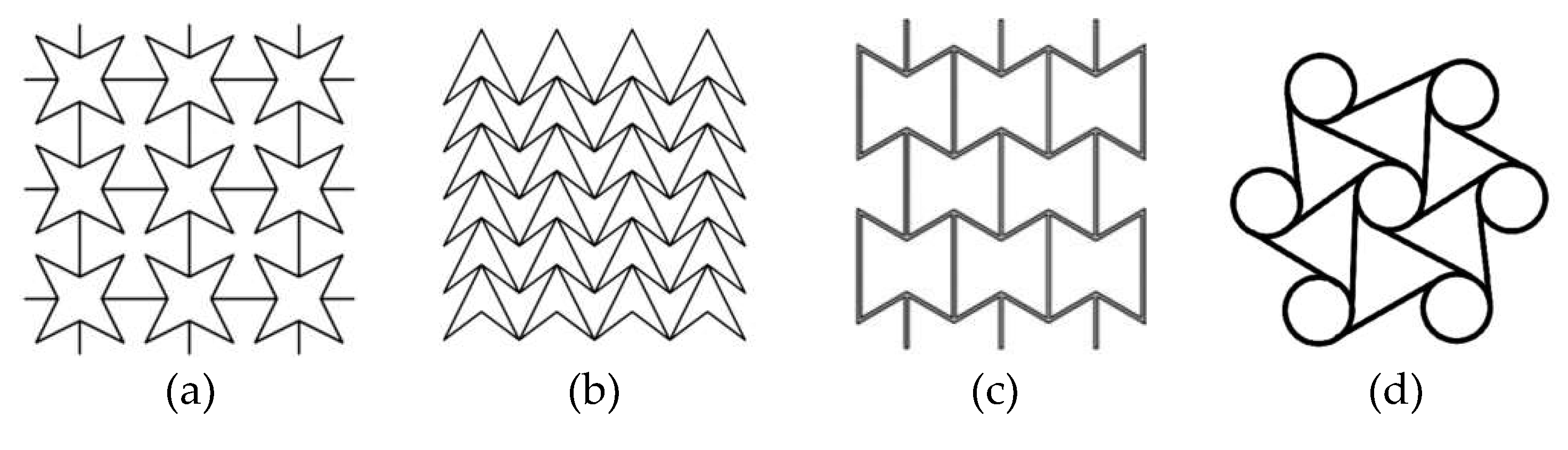
Figure 2.
Re-entrant cell structure dimensions.
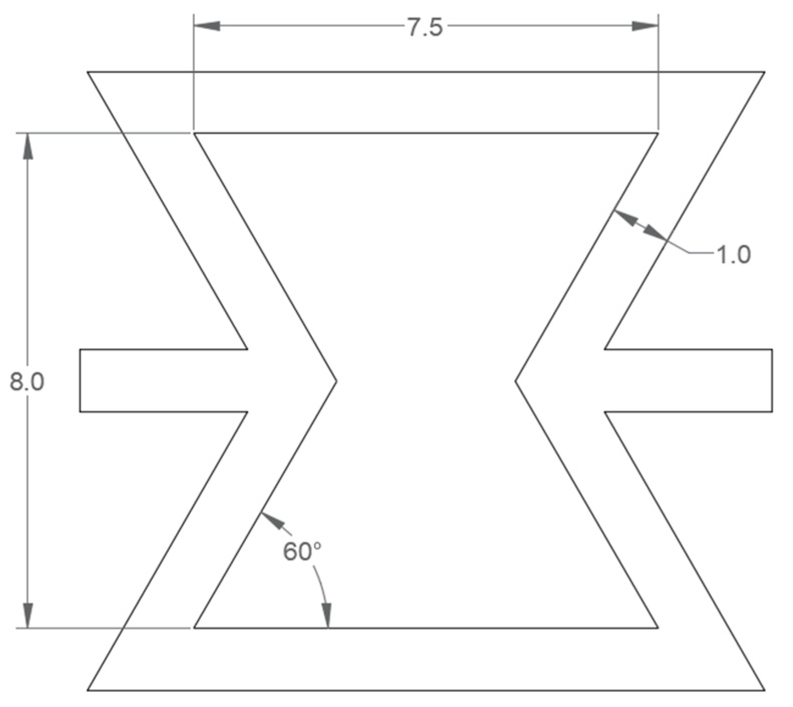
Figure 3.
Re-entrant honeycomb specimen geometry and dimensions.
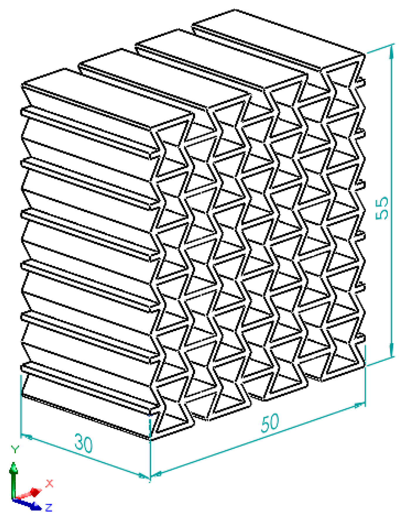
Figure 4.
Placement of the specimens on the directions of X′ (left) and Y′ (right) on the compression test apparatus plate.
Figure 4.
Placement of the specimens on the directions of X′ (left) and Y′ (right) on the compression test apparatus plate.
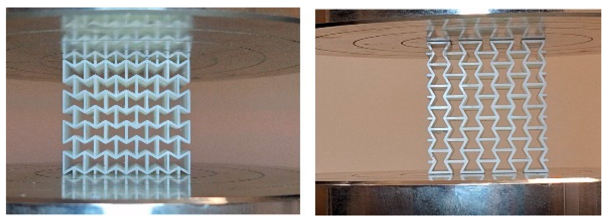
Figure 5.
Critical cross-sectional area at loading direction of X (X’).
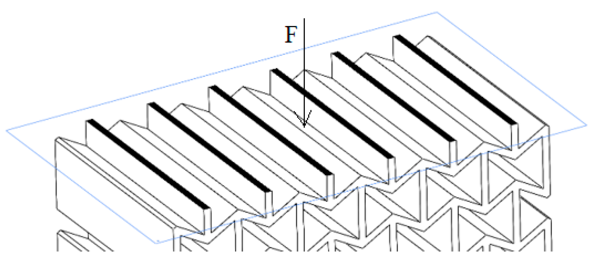
Figure 6.
Critical cross-sectional area at loading direction of Y (Y’).
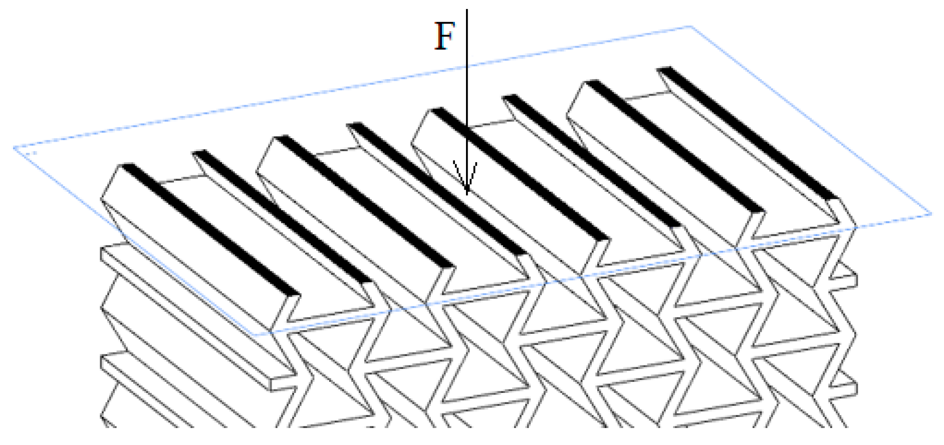
Figure 7.
Max Compressive Stress and Specific Absorbed Energy (Left) and Poisson’s Ratio (Right) Results.
Figure 7.
Max Compressive Stress and Specific Absorbed Energy (Left) and Poisson’s Ratio (Right) Results.
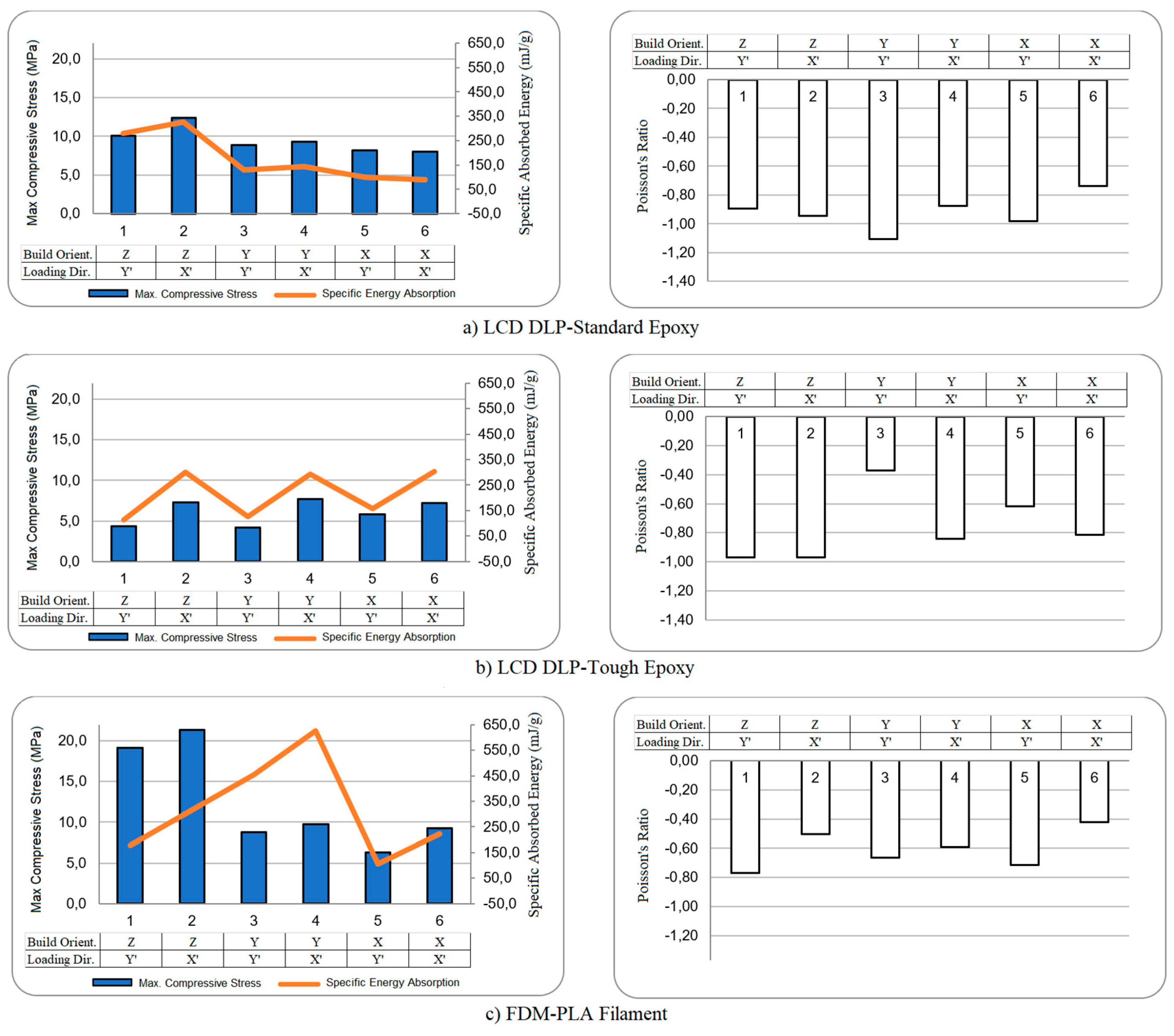
Figure 8.
Bending sideways of the tough material during compression test in Y’ direction.
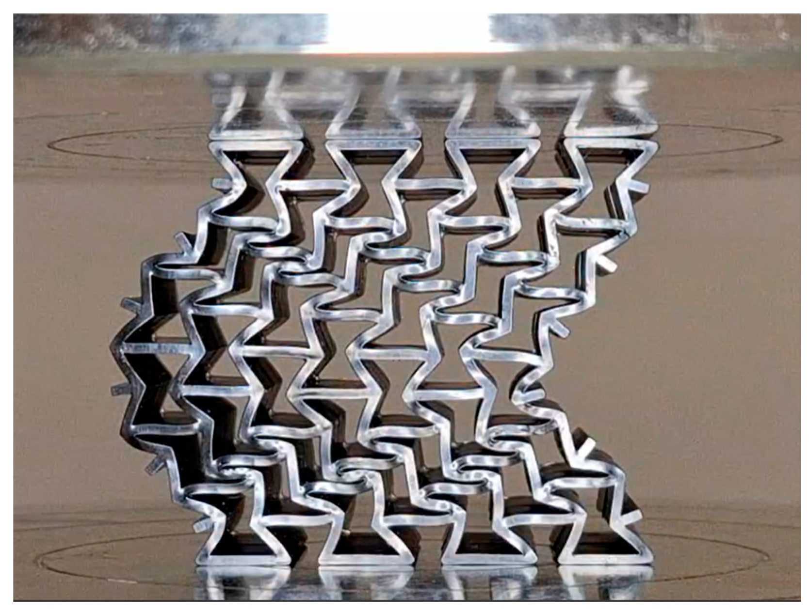

Table 1.
FDM printing settings.
| Parameters | PLA Filament |
| Layer height (mm) | 0.12 |
| Line width (mm) | 0.4 |
| Infill density | %100 |
| Print speed (mm/s) | 50 |
| Support Overhang Angle | 59 |
Table 2.
LCD-DLP printing settings.
| Parameters | Standard Resin | Tough Resin |
| Layer height (mm) | 0.05 | 0.05 |
| Bottom layer exposure time (s) | 40 | 50 |
| Build platform lift distance (mm) | 5 | 7 |
| Build platform motor speed (mm/s) | 3 | 3 |
| Delay time (s) | 2 | 3 |
Table 3.
Printing orientation and loading directions, including schematic representation of each test number.
Table 3.
Printing orientation and loading directions, including schematic representation of each test number.
| Test Type Name | Printing Orientation | Loading Direction | Schematic representation of testing according to building orientation |
| ZY’ | Z | Y’ |  |
| ZX’ | Z | X’ |  |
| YY’ | Y | Y’ |  |
| YX’ | Y | X’ |  |
| XY’ | X | Y’ |  |
| XX’ | X | X’ |  |
Disclaimer/Publisher’s Note: The statements, opinions and data contained in all publications are solely those of the individual author(s) and contributor(s) and not of MDPI and/or the editor(s). MDPI and/or the editor(s) disclaim responsibility for any injury to people or property resulting from any ideas, methods, instructions or products referred to in the content. |
© 2025 by the authors. Licensee MDPI, Basel, Switzerland. This article is an open access article distributed under the terms and conditions of the Creative Commons Attribution (CC BY) license (http://creativecommons.org/licenses/by/4.0/).
Copyright: This open access article is published under a Creative Commons CC BY 4.0 license, which permit the free download, distribution, and reuse, provided that the author and preprint are cited in any reuse.


