Submitted:
02 September 2025
Posted:
03 September 2025
You are already at the latest version
Abstract
Methane pyrolysis produces hydrogen (H₂) with a solid carbon co-product, eliminating process CO₂ formation and enabling low-carbon supply when paired with renewable or low-carbon heat. This work develops and evaluates a hybrid geothermal–pyrolysis configuration in which an enhanced geothermal system (EGS) provides baseload preheat and isothermal hold, while electrical or solar-thermal top-up delivers the final approach to the catalytic setpoint. We (i) integrate field-scale geothermal operating envelopes to anchor heat-integration targets and duty splits; (ii) expand scalability considerations to include high-pressure reactor design, thermal management, and carbon separation/handling strategies that preserve co-product value; (iii) provide a techno-economic analysis (TEA) template that itemizes CAPEX/OPEX, incorporates carbon pricing/credits, and explicitly treats dual-product economics (H₂ plus carbon black); and (iv) reorganize the state-of-the-art chronologically, linking molten-media demonstrations, catalyst advances, and recent integration studies to deployment readiness.
Process synthesis shows that allocating geothermal heat to the largest heat-capacity streams (feed, recycle, and melt/salt hold) reduces electric top-up demand and stabilizes reactor temperature, mitigating coking/sintering and narrowing carbon particle size distributions upstream of cyclones and polishing filters. High-pressure operation improves hydrogen partial pressure and equipment compactness but demands corrosion-resistant materials and careful thermal-stress management. The TEA framework—built from recent methane-pyrolysis studies and standard process-economics practice—highlights that levelized cost of hydrogen is co-dominated by (a) the specific electric duty and grid/onsite power carbon intensity and (b) the realizable price and specification of the carbon co-product; sensitivities to methane price, geothermal capacity factor, and conversion/selectivity are secondary but material. Overall, geothermal-assisted methane pyrolysis offers a practical path to turquoise hydrogen with a defensible value stack when carbon quality is preserved and heat integration is optimized. We conclude with design rules and reporting guidelines to accelerate site-specific FEED and near-term pilot deployment.
Keywords:
methane pyrolysis
; turquoise hydrogen
; geothermal
; EGS
; carbon black
; techno-economics
; heat integration
; high-pressure reactor
; molten media
; carbon handling
1. Introduction & State-of-the-Art (Chronological)
Hydrogen is central to deep decarbonization scenarios across chemicals, fuels, and heavy industry, yet the dominant route—steam methane reforming (SMR)—emits substantial CO₂ unless paired with capture and storage [7,8]. Methane pyrolysis (a.k.a. turquoise hydrogen) splits CH₄ directly to H₂ and solid carbon, eliminating process CO₂ formation at the reactor and creating a potential dual-product business model when carbon meets carbon-black specifications [1,4,9,22,33]. Compared with electrolysis, pyrolysis targets high-temperature heat rather than electricity input to water splitting; when that heat is provided by low-carbon sources and carbon is valorized, levelized H₂ cost (LCOH) can be competitive [1,3,9,21,29,30,31,32].
Two technical hurdles define deployment readiness: (i) thermal supply and control at 600–900 °C to sustain conversion/selectivity without accelerating deactivation, and (ii) carbon separation/handling to protect downstream equipment and preserve co-product value [1,2,4,10,12,23,24,33]. To address (i), we consider hybrid geothermal–pyrolysis: use an enhanced geothermal system (EGS) for preheat and isothermal hold (baseload duty), and apply electrical or solar-thermal top-up for the final temperature approach and transients [6,10,21,26,34]. To address (ii), we synthesize molten-media and gas-phase evidence on particle formation, disengagement, and polishing to meet carbon-black markets [4,12,13,21,24,33].
1.1. Why Turquoise Hydrogen Now
Recent field-scale integration studies and reviews highlight three levers that co-dominate LCOH: specific electric duty, carbon co-product price/specification, and methane price; policy credits and site heat resources modulate all three [1,2,3,4,7,9,21,22,29,30,31,32,33]. Geothermal preheat can reduce electric top-up and stabilize reactor temperature, thereby (a) mitigating coking/sintering dynamics and (b) narrowing particle size distributions upstream of cyclones/filters—both supportive of higher carbon value capture [1,4,10,12,21,24,33]. Recent system analyses of baseload and flexible EGS power/thermal delivery provide the operating envelopes to ground heat-integration targets and capacity factors [26], complemented by standard geothermal reservoir design practice [29,34].
1.2. State-of-the-Art — a Concise Chronology
2015–2017: Foundational demonstrations and the first economic framing.Liquid-metal / molten-media concepts advanced from theory to bubble-column experiments, elucidating gas–liquid mass transfer, reaction zones, and initial solid-carbon separation approaches [13]. A landmark molten-metal catalysis demonstration showed direct CH₄-to-H₂ with separable carbon, igniting modern turquoise-H₂ interest [6]. Early techno-economic work crystallized the sensitivity of costs to power demand and carbon value, setting baselines for later TEA templates [9].
2019–2021: Kinetics, catalysts, and system comparisons mature.Reviews consolidated temperature windows (~600–900 °C), catalyst families (Ni/Fe/Co; doped systems), and deactivation modes, while drawing comparisons with SMR + CCS pathways for long-term roles of hydrogen [5,7,8,10,12]. Process-level studies sharpened understanding of molten-salt and liquid-metal operation, carbon morphology, and implications for downstream handling [12,13,15]. A broad industrial context emerged in which turquoise hydrogen complements rather than replaces other routes [7,8,10].
2022–2023: Scale-relevant engineering, solar/electric heating, and carbon handling. Comprehensive reviews and mini-reviews emphasized molten-media advances and product-quality control [1,4,10]. Comparative reactor studies contrasted gas-phase versus molten-tin bubbling systems under solar input, linking temperature uniformity to particle size and filtration load [21]. Engineering studies explored plasma and H₂-combustion-heated pyrolysis concepts that simplify heat delivery while retaining CO₂-free operation [23,24]. In parallel, cyclone design literature from process engineering was tapped to specify disengagement and polishing trains suitable for carbon-laden off-gas [24].
2024–2025: Integration, high-pressure kinetics, predictive modeling, and EGS coupling.High-pressure kinetics and modeling tightened scale-up envelopes and helped define pressure–temperature trade-offs for compact equipment and improved H₂ recovery [16,19]. Predictive catalytic models are emerging to bridge laboratory selectivity with pilot reactors [19]. On the system side, power-supply characterization for EGS quantified baseload/flexible delivery relevant to hybrid heat trains [26], while TEAs extended to ammonia contexts and dual-product revenue stacking (H₂ + carbon) [25]. Across these strands, the integration narrative has shifted from proof-of-concept to site-coupled process engineering, making geothermal-assisted pyrolysis a concrete target for FEED-level design [1,2,3,4,10,16,19,20,21,22,23,24,25,26,29,30,31,32,33,34].
1.3. This Paper’s Contribution
Building on that arc, this work contributes four things tailored to deployment:
2. Concept & Real-World Anchors (EGS → Pyrolysis)
2.1. Process Concept and Duty Split (see Fig. 1)
Dry methane is preheated using an enhanced geothermal system (EGS) loop to approach the catalytic window, then receives top-up heat (electric resistive or solar-thermal) to reach the reactor setpoint (typically 600–900 °C, depending on reactor/catalyst) [1,2,10,12,21,34]. The reactor can be either (a) a molten-media bubble column (Sn/Bi or molten salts) or (b) a packed/fixed bed. Effluent hydrogen is separated and compressed, and solid carbon is recovered, de-oiled/conditioned, and sent to classification for carbon-black (CB) and related markets [4,12,13,22,33]. (see Fig. 2)
Heat-integration logic.
- ▪
- Assign EGS to baseload sensible heat on the largest heat-capacity flows (fresh CH₄, recycle, and—where applicable—the molten medium’s isothermal hold).
- ▪
- ▪
2.2. Why Geothermal Here?
2.3. Reactor Options and Operating Envelopes
Molten-media bubble column (Sn/Bi/salts).
- ▪
- ▪
- ▪
- Packed/fixed bed.
- ▪
- ▪
2.4. Hydrogen Separation & Recycle
The H₂-rich stream is routed to PSA or membrane separation and then to compression. An off-gas recycle closes the carbon balance and lifts overall CH₄ conversion; a small purge maintains inert build-up control [12,21,24,33]. EGS-assisted preheat improves separator thermal stability and can reduce electric duty swings on compressors by smoothing reactor output [10,21,26].
2.5. Carbon Handling and Value Preservation
Target handling that protects CB value and downstream assets:
- ▪
- ▪
- ▪
2.6. Controls, Start-Up, and Operability
- ▪
- ▪
- ▪
2.7. Site–EGS Coupling and Reporting Guidance
- ▪
- Match EGS temperature and flow envelope to process composite curves; document capacity factor, expected seasonality, and any flex provision (e.g., curtailed electric top-up or thermal storage if used) [26,34].Figure 1. Block flow — EGS loop → preheaters → pyrolysis reactor → H₂ separation → carbon handling.
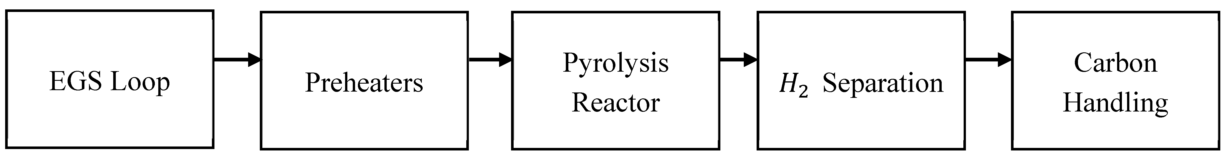 Figure 2. Pinch-style heat map — match highest ṁcₚ streams to EGS; ΔTmin and residual trim-heat ΔT annotated.Figure 2. Pinch-style heat map — match highest ṁcₚ streams to EGS; ΔTmin and residual trim-heat ΔT annotated.
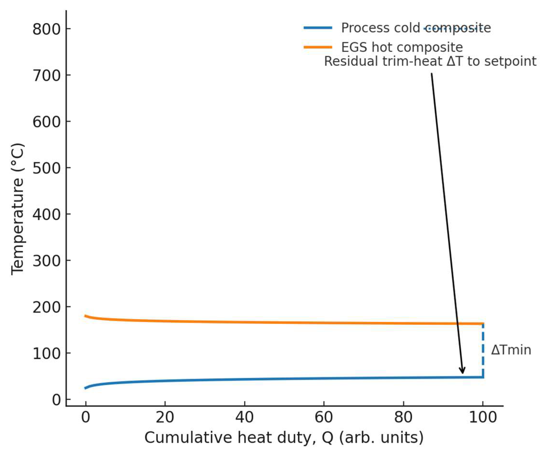
- ▪
As a real-world anchor, Utah FORGE (Milford, UT) demonstrated engineered doublet performance in Apr–May 2024: injection into 16A(78)-32 up to 15 bpm (≈630 gpm) with production from 16B(78)-32 up to 8 bpm (≈344 gpm, ~70% recovery) and outflow ≈139 °C; the target reservoir exceeds ~175 °C at ~2–2.5 km depth—quantitatively defining a baseload EGS preheat window for our integration
3. Scalability: High-Pressure Design, Thermal Management, Carbon Separation
3.1. High-Pressure Reactor Design
Operating envelope and scale-up logic
- ▪
- Why pressure? Higher pressure compacts hardware (smaller volumetric flows, smaller diameters/compressors) and improves downstream H₂ recovery (membranes/PSA utilization) at a given throughput [1,2,16]. Because increases gas moles, elevated pressure penalizes equilibrium conversion; you counterbalance with temperature and residence time. Practically, 10–25 bar with 600–900 °C is a workable FEED envelope, with setpoint chosen by catalyst/melt system and deactivation tolerance [1,2,10,12,16,21].
- ▪
-
Reactor choices at HP:
- ○
- Molten-media bubble column (Sn/Bi/salts). HP raises gas density and bubble coalescence risk; keep superficial gas velocity in a churn-turbulent window that sustains fine bubbles without flooding. Use sparger hole velocities and L/D ≈ 8–15 as starting points; confirm via hydrodynamic tests [12,13,21].
- ○
- •
- Kinetic/equilibrium guidance (design checks):
At a chosen pressure, push high enough that comfortably exceeds your per-pass target, then size residence time so with margin. Recycle closes the gap to near-complete overall conversion [1,2,10,12].
Materials & containment (HP/HT)
- ▪
- ▪
- ▪
- ▪
- Catalysts at scale (HP + thermal field)
- ▪
- ▪
- ▪
3.2. Thermal Management
Duty split (EGS vs. trim)
- ▪
- ▪
- ▪
Control strategy (scale-ready)
- ▪
-
Dual-loop temperature control.
- ▪
- ▪
3.3. Carbon Separation & Handling
Inside the reactor (primary solids management)
- ▪
- ▪
Primary separation & polishing
- ▪
- ▪
- ▪
- Value preservation and product finishing
- ▪
- ▪
- ▪
3.4. Practical Design Rules (Ready for the Methods Box)
- ▪
- Pressure & T: Start FEED with 10–25 bar, 600–900 °C; verify ) and ; close with recycle.
- ▪
- ▪
- ▪
- ▪
4. Techno-Economic Analysis (TEA)
4.1. Scope & Cases
Plant basis. Nameplate ~10 kt H₂·yr⁻¹ (≈ 1.25 t H₂·h⁻¹ at 8,000 h·yr⁻¹), EGS-assisted preheat, single site boundary from methane reception to H₂ product delivery and carbon product bins. Units included: methane conditioning, preheaters, trim heater, pyrolysis reactor(s), molten-media/salt inventory (if applicable), H₂ separation and compression, carbon handling (sump/tempered quench, cyclone, porous ceramic filters, classifier), HX trains, electrical and/or solar top-up, and plant controls/utilities. TEA framing follows molten-media/fixed-bed literature and reviews [1,2,4,9,21]; costing follows standard process-economics methods [30,31,32] with geothermal design context from [34].
Comparison set.
- ▪
- EGS + electric top-up: EGS supplies baseload sensible preheat/isothermal hold; electric provides last-mile ΔT and transients.
- ▪
- Solar-thermal + electric: solar field (and, if used, thermal storage) supplies preheat; electric trims to setpoint.
- ▪
- Electric-only: all duty from electric heaters (simplest hardware; highest kWh exposure).
Boundary notes. Owner’s costs, working capital, land, and grid interconnection fees can be carried as indirects; EGS can be owned (CAPEX for wells & tie-in) or contracted as purchased thermal duty (OPEX). Cases A–C share identical process hardware except for the heat-supply block.
4.2. Cost Structure
CAPEX (installed):
- ▪
- ▪
- ▪
- ▪
- ▪
Cost estimation by Bare-Module / Lang-factor or equipment-factored methods per [30,31,32]; EGS well costs and surface tie-ins follow geothermal practice [34].
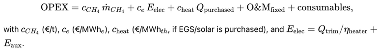
OPEX (annual):
- ▪
- ▪
- Consumables: catalyst/melt make-up, filtration media, inert gases; water for quench/utility.
- ▪
Throughput-linked stoichiometry. For : 4 kg CH₄ per 1 kg H₂ at 100% overall conversion; 3 kg C per 1 kg H₂ formed. Let be overall CH₄-to-H₂ yield (after recycle); then:
with the saleable carbon-black fraction after classification.
4.3. Revenue & Policy Levers
- ▪
- H₂ product. Off-take price depends on delivery pressure/purity and contract tenor; compression costs scale with setpoint and pipeline/storage spec.
- ▪
- ▪
- Carbon credits / policy. Stack production credits or market-based carbon prices where eligible; LCOH sensitivity is strong to this term when power carbon intensity (CI) is low and carbon sale value is high [7,8,9,27,29]. Cases with EGS preheat reduce electric demand, improving both cost and CI exposure [1,4,21,26,34].
4.4. Calculation Framework
Define the levelized cost of hydrogen:
Case-specific heat terms (duty split):
- ▪
- EGS + electric: covers preheat/isothermal hold, the last-mile ΔT and transients.
- ▪
- Solar-thermal + electric: replace with ; storage adds CAPEX and reduces electric exposure.
- ▪
- Electric-only: ≈ (highest kWh exposure; simpler CAPEX).
OPEX decomposition (per year):
4.5. Sensitivities & Expected Findings
Sensitivity set: CH₄ price, electricity price/CI, EGS (or solar) capacity factor, carbon sale price/grade split, overall conversion/selectivity, and discount rate. Prior TEA work shows carbon revenue and electric demand are the dominant levers [9], consistent with the heat-split strategy that shifts duty to EGS/solar [1,4,21,26,34].
Typical qualitative outcomes (at equal H₂ output):
- ▪
- EGS + electric: lowest LCOH where EGS CF is high and purchased/owned geothermal heat is economical; strong resilience to power price/CI swings.
- ▪
- Solar-thermal + electric: improved CI and reduced kWh exposure vs (C); CAPEX rises (field + storage) and economics hinge on solar CF and storage sizing.
- ▪
- Electric-only: simplest CAPEX, highest LCOH variance with electric price/CI; a useful baseline for comparing A/B.
Implementation checklist (for your model workbook)
- ▪
- Fix nameplate → annual H₂ via capacity factor; compute CH₄, C via stoichiometry × yields.
- ▪
- Break CAPEX into blocks; apply CRF; add OPEX components.
- ▪
- Calculate and from your heat-integration (Fig. 2); convert to electricity.
- ▪
- Add revenues: H₂ off-take, carbon grade mix, policy credits.
- ▪
- Run A/B/C and the sensitivity set; report tornado bars for LCOH and identify breakeven thresholds (e.g., carbon price vs. electricity price).
5. Methods (What to Report so Reviewers Can Reproduce)
5.1. Process Basis and Heat-Integration Data (see Fig. 2)
Report the system boundary, operating mode, and full composite-curve inputs so an independent team can rebuild the heat match.
Minimum items to publish (data table):
- ▪
- Basis & boundary: nameplate H, capacity factor, overall yield after recycle, site ambient.
- ▪
- ▪
- Process cold streams (each): identification (fresh , recycle, melt hold if applicable), mass flow mean correlation, inlet/outlet T, allowable approach
- ▪
- Process hot streams (each): if any internal hot utility is matched, provide , , T-in/T-out.
- ▪
- Pinch reconstruction: composite curves (T vs. cumulative ) for EGS supply and process demand; annotated pinch and residual trim-heat pre-setpoint (Fig. 2).
- ▪
Calculation notes (publishable):
; show how was selected (e.g., 10–20 K) and how residual maps to electric load .
5.2. Reactor Details (Geometry, HP/HT Envelope, Internals)
Provide enough hardware and operating detail to permit a rate-based model and pressure-drop check.
Common to all reactor types:
- ▪
- Type & flow scheme: molten-media bubble column vs. packed/fixed bed; co-current/counter-current arrangements.
- ▪
- Geometry: ID/OD, effective height/length, L/D, number of parallel trains; nozzle sizes and sparger pattern (if molten).
- ▪
- Operating points: pressure, reactor setpoint temperature (°C), axial/radial temperature uniformity targets, residence time τ\tauτ definition.
- ▪
- Throughput: fresh CH₄, recycle ratio, total superficial velocity; pressure-drop targets and measured values.
Molten-media specifics:
- ▪
- Medium: alloy/salt identity and composition, total inventory (kg), make-up/bleed, liquidus/solidus temperatures.
- ▪
- ▪
- ▪
- Packed/fixed-bed specifics:
- ▪
- Catalyst: active metals (Fe/Co/Ni), promoter/support, pellet size & porosity; total loading (kg).
- ▪
- ▪
- Kinetics & performance reporting:
- ▪
- Conversion, H₂ selectivity/yield, deactivation rate (e.g., %/100 h), carbon production rate and removal cadence; publish data as
- ▪
- contours or time-on-stream plots.
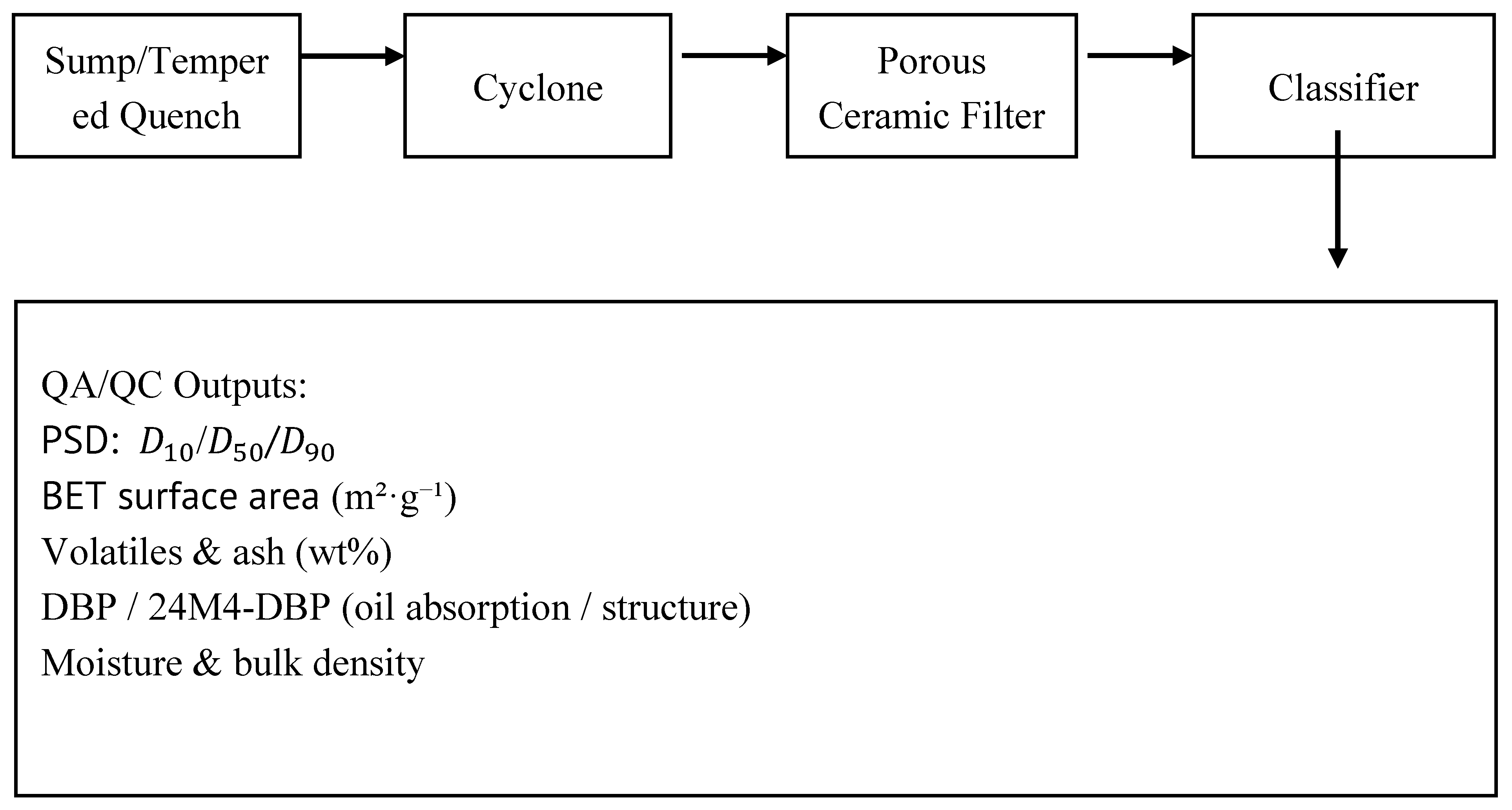
5.3. Carbon QA/QC (Methods That Tie to Economics) (see Fig. 3)
Report the exact analytical methods and sample handling—these drive co-product value.
Minimum QA/QC panel (with methods): (see Fig. 3)
- ▪
- PSD: // by laser diffraction (report dispersant, sonication power/time, refractive index model).
- ▪
- Surface area: BET (report degassing temp/time, model fit domain).
- ▪
- Volatiles & ash: thermogravimetry or muffle procedure and temperatures/hold times; residual metals if relevant.
- ▪
- Oil absorption (DBP) or alternative structure metric.
- ▪
- Moisture and surface chemistry (if priced): elemental O/H, functional groups (e.g., Boehm titration or XPS).
- ▪
5.4. TEA Inputs (so the Numbers Are Reproducible)
Document parameters and models used for costs and finance; point to raw sources or date-stamped indices.
Costing framework (publish):
- ▪
- ▪
- Indices & currencies: cost index used (e.g., CEPCI or equivalent), base year, currency, escalation method.
- ▪
- WACC & finance: nominal/real WACC, tax rate, depreciation method (MACRS/SL), plant life nnn, discount rate iii; show CRF:
Figure 3.
Carbon-handling train — sump/tempered quench → cyclone → porous ceramic filter → classifier; QA/QC outputs. (see Fig. 3).
Figure 3.
Carbon-handling train — sump/tempered quench → cyclone → porous ceramic filter → classifier; QA/QC outputs. (see Fig. 3).
- ▪
- ▪
Model disclosure: upload the calculation workbook (tabs: Assumptions, Heat Split, CAPEX, OPEX, Revenues, LCOH, Sensitivity) and list equation references (e.g., LCOH definition in §4.4) with cell ranges.
5.5. Data & Code Availability
Provide (i) composite-curve data (.csv), (ii) anonymized TEA workbook, (iii) reactor performance dataset (time-on-stream), and (iv) QA/QC raw outputs. If a site-specific EGS dataset is non-public, include a synthetic but structurally equivalent trace plus bounds so others can rerun Fig. 2 [21,26,34].
6. Conclusions
Geothermal-assisted methane pyrolysis couples a steady, low-carbon heat backbone (EGS) with a high-temperature catalytic conversion that thrives on isothermal stability. The integration:
Immediate path to pilot. (i) Use EGS for preheat/isothermality; (ii) select an HPHT reactor/catalyst pair with proven thermal uniformity; (iii) design the carbon-handling train (sump → cyclone → ceramic filter → classifier) around CB specifications; (iv) structure TEA with transparent CAPEX/OPEX blocks, carbon credits, and carbon co-product revenues. With the curated literature and standard design texts [1,2,3,4,5,6,7,8,9,10,11,12,13,14,15,16,17,18,19,20,21,22,23,24,25,26,27,28,29,30,31,32,33,34], the concept is sufficiently anchored to proceed to site-specific FEED and pilot demonstration.
References
- S. R. Patlolla, K. Katsu, A. Sharafian, K. Wei, O. E. Herrera, and W. Mérida, “A review of methane pyrolysis technologies for hydrogen production,” Renew. Sustain. Energy Rev., vol. 181, p. 113323, Jul. 2023. [CrossRef]
- M. McConnachie, M. Konarova, and S. Smart, “Literature review of the catalytic pyrolysis of methane for hydrogen and carbon production,” Int. J. Hydrogen Energy, vol. 48, no. 66, pp. 25660–25682, Aug. 2023. [CrossRef]
- A. Lotfollahzade Moghaddam, S. Hejazi, M. Fattahi, M. G. Kibria, M. J. Thomson, R. AlEisa, and M. A. Khan, “Methane pyrolysis for hydrogen production: Navigating the path to a net zero future,” Energy Environ. Sci., vol. 18, no. 3, pp. 1034–1056, 2025. [CrossRef]
- Z. Lang, Z. Yanshaozuo, X. Shu, C. Ganming, and D. Huamei, “A mini-review on hydrogen and carbon production from methane pyrolysis by molten media,” Energy Fuels, vol. 38, no. 24, pp. 23175–23191, Dec. 2024. [CrossRef]
- N. Sánchez-Bastardo, R. Schlögl, and H. Ruland, “Methane pyrolysis for CO₂-free hydrogen production: A green process to overcome renewable energies unsteadiness,” Chem. Ing. Tech., vol. 92, no. 10, pp. 1596–1609, Oct. 2020. [CrossRef]
- D. C. Upham, V. Agarwal, A. Khechfe, Z. R. Snodgrass, M. J. Gordon, H. Metiu, and E. W. McFarland, “Catalytic molten metals for the direct conversion of methane to hydrogen and separable carbon,” Science, vol. 358, no. 6365, pp. 917–921, Nov. 2017. [CrossRef]
- J. O. Abe, A. P. I. Popoola, E. Ajenifuja, and O. M. Popoola, “Hydrogen energy, economy and storage: Review and recommendation,” Int. J. Hydrogen Energy, vol. 44, no. 29, pp. 15072–15086, Jun. 2019. [CrossRef]
- Z. Navas-Anguita, D. García-Gusano, J. Dufour, and D. Iribarren, “Revisiting the role of steam methane reforming with CO₂ capture and storage for long-term hydrogen production,” Sci. Total Environ., vol. 771, p. 145432, Jun. 2021. [CrossRef]
- B. Parkinson, J. W. Matthews, J. B. McConnaughy, D. C. Upham, and E. W. McFarland, “Techno-economic analysis of methane pyrolysis in molten metals: Decarbonizing natural gas,” Green Chem., vol. 21, no. 17, pp. 4632–4640, Sep. 2019. [CrossRef]
- T. I. Korányi, M. Németh, A. Beck, and A. Horváth, “Recent advances in methane pyrolysis: Turquoise hydrogen with solid carbon production,” Energies, vol. 15, no. 17, p. 6342, Aug. 2022. [CrossRef]
- G. Karayel, I. Dincer, and N. Javani, “Green hydrogen production potential in Turkey with wind power,” Int. J. Green Energy, vol. 20, no. 2, pp. 129–138, 2023. [CrossRef]
- C. F. Patzschke, J. Riemann, K. M. V. Abraham, P. J. Brown, and C. S. Adjiman, “Co-Mn catalysts for H₂ production via methane pyrolysis in molten salts,” Chem. Eng. J., vol. 414, p. 128730, Jun. 2021. [CrossRef]
- M. Plevan, T. Geißler, A. Abánades, K. Mehravaran, R. K. Rathnam, C. Rubbia, and D. Salmieri, “Thermal cracking of methane in a liquid metal bubble column reactor: Experiments and kinetic analysis,” Int. J. Hydrogen Energy, vol. 40, no. 25, pp. 8020–8033, Jul. 2015. [CrossRef]
- D. Kang, N. Rahimi, and K. J. Smith, “Catalytic methane pyrolysis in molten MnCl₂-KCl,” Appl. Catal. B: Environ., vol. 254, p. 659, Oct. 2019. [CrossRef]
- E. Meloni, M. Martino, and V. Palma, “A short review on Ni-based catalysts and related engineering issues for methane steam reforming,” Catalysts, vol. 10, no. 3, p. 352, Mar. 2020. [CrossRef]
- A. Punia, L. Prat, and A. Ayache, “Analysis of methane pyrolysis experiments at high pressure: Goal-oriented estimations of kinetics,” Chem. Eng. J., vol. 471, p. 144183, 2023. [CrossRef]
- S. Sorcar and B. A. Rosen, “Methane pyrolysis using a multiphase molten metal reactor,” ACS Catal., vol. 13, no. 15, pp. 10161–10166, 2023. [CrossRef]
- C. J. Palmer, A. S. Puckett, A. W. Behn, M. J. Gordon, and E. W. McFarland, “Methane pyrolysis with a molten Cu–Bi alloy catalyst,” ACS Catal., vol. 9, pp. 8337–8345, 2019. [CrossRef]
- U. Pototschnig, P. Yin, M. Sattler, M. C. Korać, and M. Koller, “A predictive model for catalytic methane pyrolysis,” J. Phys. Chem. C, Early Access, 2024. [CrossRef]
- F. Rosner, T. Bhagde, D. S. Slaughter, V. Zorba, and J. Stokes-Draut, “Techno-economic and carbon dioxide emission assessment of carbon black production,” J. Cleaner Prod., vol. 436, p. 140224, 2024. [CrossRef]
- B. Msheik, S. Rodat, E. Villermaux, and S. Abanades, “Experimental comparison of solar methane pyrolysis in gas-phase and molten-tin bubbling tubular reactors,” Energy, vol. 260, p. 124943, 2022. [CrossRef]
- O. Daghagheleh, H. B. Karimipour, and M. H. Sarrafzadeh, “Feasibility of a plasma furnace for methane pyrolysis,” Energies, vol. 17, no. 1, p. 167, 2023. [CrossRef]
- T. Uehara, K. Takao, S. Sato, and Y. Takeno, “CO₂-free hydrogen production by methane pyrolysis using hydrogen combustion heat,” Energies, vol. 17, no. 2, p. 367, 2024. [CrossRef]
- W. Wang, Y. Wang, B. Wang, X. Su, and F. Wang, “The secondary flows in a cyclone separator: A review,” Processes, vol. 11, p. 2935, 2023. [CrossRef]
- M. R. G. Pangestu and U. Zahid, “Techno-economic analysis of integrating methane pyrolysis and reforming for low-carbon ammonia production,” Energy Convers. Manag., vol. 322, p. 119125, 2024. [CrossRef]
- M. J. Aljubran, A. G. Gandomi, A. Al-Aali, and H. A. Al-Khalidi, “Power supply characterization of baseload and flexible enhanced geothermal systems,” Sci. Rep., 2024. [CrossRef]
- N. Sánchez-Bastardo, R. Schlögl, and H. Ruland, “Methane pyrolysis for zero-emission hydrogen production,” Ind. Eng. Chem. Res., vol. 60, no. 34, pp. 11855–11881, 2021. [CrossRef]
- H. Kim, H. Kim, S. Kim, S. Lee, and J. Kim, “Hydrogen production in methane decomposition reactor using solar thermal energy,” Appl. Sci., vol. 11, no. 21, p. 10333, 2021. [CrossRef]
- R. DiPippo, Geothermal Power Plants: Principles, Applications, Case Studies and Environmental Impact, 4th ed. Oxford, U.K.: Butterworth–Heinemann (Elsevier), 2015.
- G. Towler and R. K. Sinnott, Chemical Engineering Design: Principles, Practice and Economics of Plant and Process Design, 3rd ed. Oxford, U.K.: Elsevier, 2022.
- D. W. Green and M. Z. Southard (eds.), Perry’s Chemical Engineers’ Handbook, 9th ed. New York, NY, USA: McGraw–Hill, 2019.
- M. S. Peters, K. D. Timmerhaus, and R. E. West, Plant Design and Economics for Chemical Engineers, 5th ed. New York, NY, USA: McGraw–Hill, 2003.
- J.-B. Donnet, R. C. Bansal, and M.-J. Wang, Carbon Black: Science and Technology, 2nd ed. New York, NY, USA: Marcel Dekker, 1993.
- M. Grant and P. Bixley, Geothermal Reservoir Engineering, 2nd ed. Burlington, MA, USA: Academic Press, 2011.
Disclaimer/Publisher’s Note: The statements, opinions and data contained in all publications are solely those of the individual author(s) and contributor(s) and not of MDPI and/or the editor(s). MDPI and/or the editor(s) disclaim responsibility for any injury to people or property resulting from any ideas, methods, instructions or products referred to in the content. |
© 2025 by the authors. Licensee MDPI, Basel, Switzerland. This article is an open access article distributed under the terms and conditions of the Creative Commons Attribution (CC BY) license (https://creativecommons.org/licenses/by/4.0/).
Copyright: This open access article is published under a Creative Commons CC BY 4.0 license, which permit the free download, distribution, and reuse, provided that the author and preprint are cited in any reuse.


