Submitted:
02 September 2025
Posted:
03 September 2025
You are already at the latest version
Abstract
Intelligent reflecting surface assisted unmanned aerial vehicles (IRS-UAVs) have been widely applied in various communication scenarios. This paper addressed the uplink communication problem in wireless sensor networks (WSN) by proposing a novel double IRS-UAVs assisted framework to improve the pairwise sum rate. Specifically, the base station (BS) received signals to users at a relatively short distance through a single-reflection link of one IRS, and received signals to users at a relatively long distance through the double-reflection link of two IRSs. Within each work cycle, the IRS-UAVs followed a fixed service sequence to cyclically assist all sensor node pairs. We designed a joint optimization algorithm that simultaneously optimized the UAV trajectories and IRS phase shifts to maximize the pairwise sum rate, while guaranteeing each node’s transmission rate meets a minimum quality of service (QoS) constraint. The proposed algorithm decomposed the optimization problem into multiple sub-problems and conducted iterative optimization, leading to the derivation of the optimal solution. Numerical results indicate that this algorithm can effectively optimize flight trajectories of the UAVs and significantly enhance the pairwise sum rate of the system.
Keywords:
Intelligent reflecting surface (IRS)
; unmanned aerial vehicle (UAV)
; wireless sensor networks (WSN)
; trajectory optimization.
1. Introduction
In recent years, intelligent reflecting surface (IRS) has gradually matured and been widely applied in actual communication scenarios. It has the characteristics of low deployment cost and flexible deployment locations. It is usually deployed on the outer layer of high-rise buildings to cope with the situation where there are many obstacles in the direct connection channels. However, the position of IRS is difficult to change after deployment and cannot adapt to the situation where the receiving source location is variable [1,2,3].
To address the above problems, some studies have proposed combining unmanned aerial vehicle (UAV) with IRS to utilize the high maneuverability of UAVs to meet the needs of users with real-time changing positions [4,5,6].
In [7], the authors compared the performance of the relay system in three modes (UAV-only, IRS-only and IRS-UAV) and maximize the system reachable rate by optimizing the number and deployment height of IRS reflectors. The author in [8] also introduced IRS-assisted UAVs (IRS-UAVs) to optimize the NOMA network. By optimizing the phase of IRS, resource allocation and the trajectory of UAVs, the total energy consumption of the system is reduced. In [9], the authors studied the multi-user symbiotic radio (SR) system assisted by IRS-UAV. They developed an iterative algorithm based on block coordinate descent (BCD) technology to meet the minimum communication rate requirements and minimized the maximum bit error rate (BER) among all ground devices (GDs). In [10], the author proposed to improve the network coverage of the IRS-UAV communication system by increasing the number of base stations (BS). In addition, the joint optimization of multiple UAVs can further improve the performance of the system. In [11], the joint IRS selection and beamforming optimization problem had been investigated in multiple IRS-UAV-assisted anti-jamming device-to-device (D2D) networks. Furthermore, the authors in [12] proposed an IRS-assisted multilayer UAV network and analyzed the symbolic error rate and outage probability.
Although many studies have explored the combination of UAVs and IRSs, most of them focus on the optimization problem in the scenario with only single–reflection links. However, as urban density rises, the number of required cells (or users) has significantly increased. The coverage area of an IRS-UAV is difficult to meet the requirements of large-scale network. Therefore, increasing the number of IRS-UAVs involved in communication and taking advantage of double-reflection links can greatly improve network coverage. In [13], the novel IRS-assisted cognitive UAV systems (CUAVS) were investigated. However, the IRS cannot be moved freely. The authors studied an IRS-UAV wireless-powered mobile edge computing (MEC) system, where multiple IRS-UAVs were considered between Internet of Things (IoT) devices and the BS to improve the computation bits and energy harvesting in [14], but they overlooked the interconnectedness of IRSs.
In this paper, we consider a novel IRS-UAVs assisted the uplink of wireless sensor networks (WSN), where the BS can provide services to sensor nodes in a farther area through a double-reflection link of two IRSs. Compared with the traditional single IRS-assisted UAV system, this system can significantly enhance the network coverage by simultaneously optimizing the flight trajectories of two UAVs and the beamforming of the IRSs. We formulated the corresponding optimization problem, but due to the intercoupling among the optimization variables, it is difficult to solve. We proposed an algorithm that first divides the original problem into multiple sub-problems and introduces slack variables, then solves them iteratively via a joint optimization framework. The simulation results show that, compared with traditional scheme where UAVs fly from a user’s location to another’s, the proposed algorithm can significantly enhance the sum rate of the system at each stage.
2. System Model and Problem Formulation
2.1. System Model
In this section, we consider the uplink communication scenario of two IRS-UAVs in Figure 1, which involves two coverage holes: one located proximal to the BS and another positioned distally, comprising and sensor nodes, respectively. There are two IRS-UAVs that perform the communication mission at altitude H employing time division multiple access (TDMA). Continuous trajectories are represented with N discrete coordinates. For each pair of sensor nodes corresponding to the two covering holes, they are denoted as and . Their locations are represented by and respectively. and are the positions of the UAVs, which are assumed to be co-located with the IRSs. The discrete trajectory satisfies the following constraints as
where represents the maximum flight speed of UAV, represents the time length of each time slot, n demotes the index of time slots.
Due to the obstruction, the sensor nodes and BS cannot communicate directly with each other. We assume both IRS-UAVs operate with identical service cycles of duration T, where sensor nodes within the same coverage hole are allocated equal uplink transmission time slots. In time slot n, the distances of BS-, BS-, - and - are denoted by , , , , respectively. IRS-assisted communication channel is composed of line-of-sight (LoS) and non-line-of-sight (NLoS) components. As the deployment position of IRS is raised, the probability of LoS will keep increasing. Especially in remote areas, when the altitude exceeds 40 meters, the probability of LoS will approach 100% [15]. In this case, we assume that all the channels of the system are approximately equivalent to LoS channels without obstacles. The channel from node i to j, with can be modeled in the following general from
where is the complex channel gain of the link with denoting its channel power gain at the reference distance of 1 m, denoting the signal wavelength, denoting the distance from node i to j, and denoting the pass-loss exponent. Moreover, and denote respectively the azimuth (or elevation) angle-of-arrival (AoA) at node j and angle-of-departure (AoD) at node i w.r.t. the IRS plane, denotes the number of elements of denotes the receive array response from node i to j and denotes the transmit array response from node i to j.
The inter-IRS channel between and , namely
In time slot n, the effective channels BS-- and BS---, denoted by and , respectively, are given by
where , and denote the channels from to , to , BS to , and BS to respectively. denotes the reflection matrix of and the definition of is similar, which can be given by
The corresponding achievable rates from BS to uk1 and BS to sk2 in bits per second per Hertz (bps/Hz), denoted by and , respectively, are thus given by
where denotes the noise power, P represents the transmission power of BS.
In each time slot, only one pair of sensor nodes establish a communication link with the BS. At the same time, ensure that the transmission rate of each node can meet the minimum quality of service (QoS) standard, which is expressed as
where represents the minimum communication rate requirement for each node. Thus, the sum rate of the sensor nodes in time slot n can be expressed as
2.2. Problem Formulation
Our research aims to maximize the sum rate under the constraints of the phase shifts of IRSs and the trajectories of UAVs, in which , and .
Thus, this problem is expressed as
Due to the existence of binary and coupled variables, this problem is difficult to be solved directly. To address (P1), we propose an algorithm to derive the second-best solution.
3. Proposed Algorithm
Taking into account the inherent complexity of the coupling variables, we will obtain an effective solution by splitting the original problem into two sub-problems and solving them iteratively. Firstly, given the trajectories of the UAVs, we obtain the optimal phase shift. Then, we optimize the trajectories of the UAVs using the successive convex approximation (SCA) technique. These two sub-problems can be solved separately through iterative algorithms.
3.1. Phase Shift Optimization
When operating on sensor node uk1, the optimal phase of can be obtained as
where . At this time, 7 can be restated as
3.2. Trajectory Optimization
After acquiring the phase shifts of IRSs, the trajectories of the UAVs can be derived by solving the following optimization problem.
It is very difficult to solve (P2.1) directly, so we employ slack variables to replace , satisfying
Therefore, we can rewrite (13) as
where . The second order derivative of with respect to can be written as . It is obvious that the second order derivative is larger than 0 when and are satisfied. We can use SCA technology to obtain the lower limit of .
3.3. Joint Optimization of Trajectory and Phase Shift Algorithm
Based on the solutions to the sub-problems proposed in the above sections, we can obtain the maximum sum rate by iteratively solving these sub-problems. The algorithm for joint trajectory and phase shift design is summarized in Algorithm 1.

Table 1.
This is a table caption. Tables should be placed in the main text near to the first time they are cited.
Table 1.
This is a table caption. Tables should be placed in the main text near to the first time they are cited.
| Algorithm 1 Proposed Solution for (P1). |
|---|
| Initialize: Set and . |
| Repeat |
| Given , obtain the optimal phase shift based on (12), (14); |
| Given , obtain the optimal phase shift based on (15); |
| Given , obtain the optimal trajectory based on (23); |
| Given , obtain the optimal trajectory based on (18); |
| Update the iterative number ; |
| Until convergence. |
The computational complexity of the joint IRS phase shift and UAV trajectory optimization algorithm in this paper is dominated by its iterative decomposition framework and core input scales. The algorithm converges after a constant number of outer iterations , with each iteration involving two sub-problems. For IRS phase shift optimization, since the optimal phase of each of the IRS elements is computed via (1)arg(·) operations and phase adjustment is required for each of the N UAV trajectory discretization slots (core input scale), its complexity per outer iteration is . For UAV trajectory optimization, the non-convex problem is transformed into convex sub-problems via SCA. Each convex subproblem, solved by interior-point methods, involves variables and constraints, leading to a complexity of . Summing the two subproblems and incorporating , the overall time complexity of the algorithm is .
4. Numerical Results
This section conducts simulation experiments to demonstrate the effectiveness of the joint trajectory optimization algorithm. Establish a three-dimensional Cartesian coordinate system with the BS as the origin. The closer coverage holes have four sensor nodes, while the farther ones have three nodes, namely, , . BS is located at , and , , , , , and . We assume that the communicating order in one working cycle is predetermined as . The UAVs fly at a fixed altitude m with the maximum flight speed m/s and m/s. The spacing of the IRS elements is , where m. Other parameters are set as dB, , dBm, dBm, , and Hz/bps [16].
Figure 2 shows the flight trajectories of each period within one working cycle with s. We use different colors to distinguish the current communication nodes involved. The UAV equipped with the IRS changes its trajectory to approach the nodes as the mission period increases.
To further demonstrate the effectiveness of the proposed algorithm, three distinct trajectory optimization schemes are introduced for comparison. It is well established that the maximum signal-to-noise ratio (SNR) is achieved when the IRS is positioned close to the nodes or BS, whereas an active relay is typically deployed between the node and BS [1]. Therefore, two traditional trajectory schemes are introduced as benchmark schemes in this paper: one is that the IRS-UAVs fly around nodes along a straight-line trajectory; the other is that the IRS-UAVs hover at fixed points within each coverage hole, respectively. (1) Proposed scheme, which is given by Algorithm 1. (2) Line1 scheme, where the UAV flies from one node to the next at constant speed. (3) Hovering scheme, where the UAVs hover in the geometric center. The times of different communication pairs are equally distributed in the comparison scheme.
Compared to the traditional trajectory schemes, it can be observed that the flight trajectory of the UAV within one cycle exhibits a similar trend to the inter - node connection line. Nevertheless, due to multiple constraints such as the UAV’s maximum flight speed, working cycle and so on, the circular trajectory is always shorter than the inter - node connection line.
Meanwhile, as this paper assumes the communication link to be a LoS link, Node in the farther coverage hole often achieves a higher transmission rate than Node in the closer coverage hole, as it constructs an uplink via both dual-reflection and single-reflection links. This also explains why the flight trajectory of is more consistent with the traditional trajectory than that of .
Figure 3 illustrates the comparison between the proposed optimization scheme and the traditional scheme in terms of each period and sum rate. Under the traditional trajectory, nodes cannot ensure that the transmission rate remains optimized throughout the transmission time; thus, the proposed algorithm is significantly superior to the unoptimized traditional scheme. Furthermore, as the optimized flight trajectory is shorter than the traditional one, the UAV may hover at a certain position until the next node requires service.
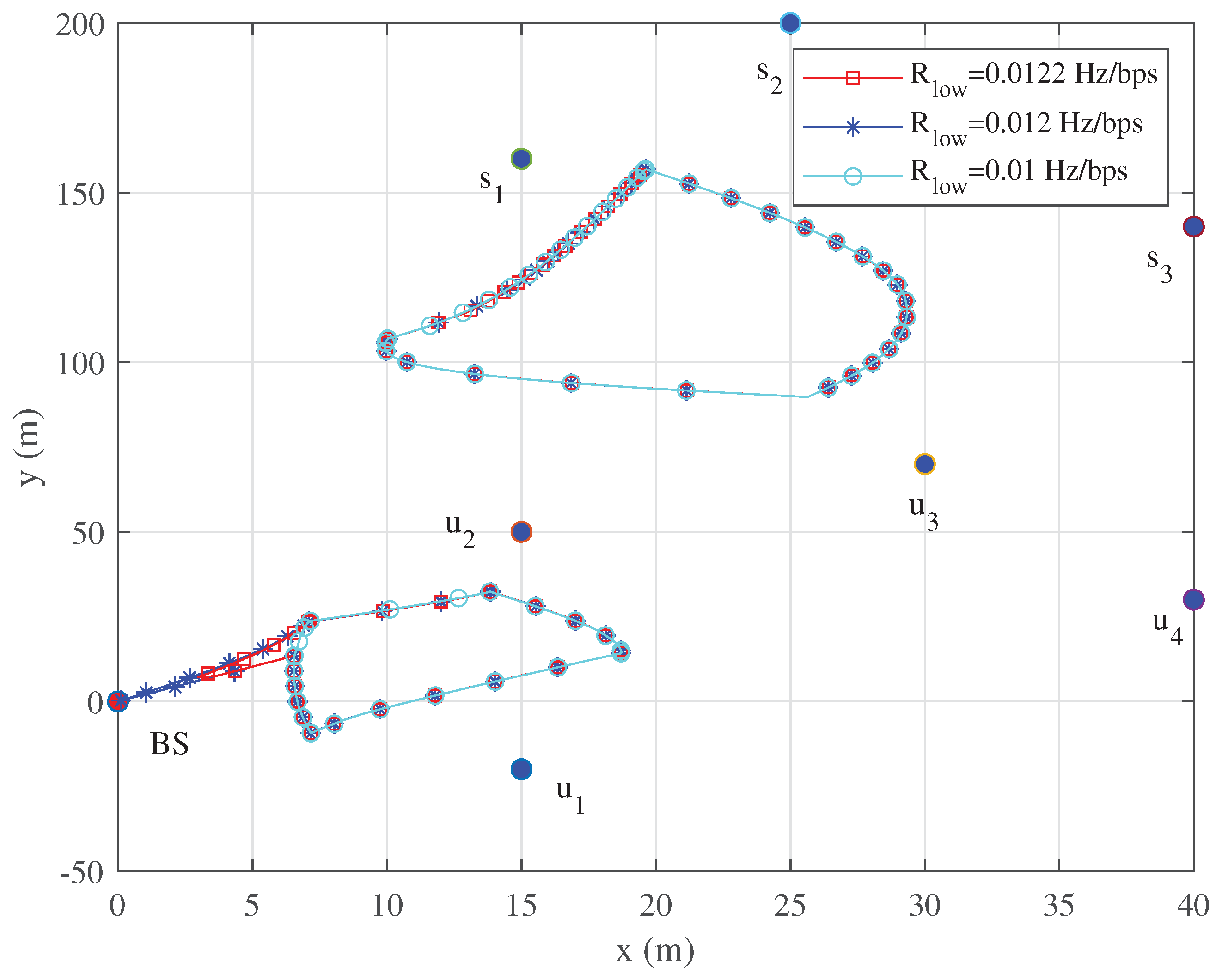
Figure 4 shows the flight trajectories of UAVs during one working cycle with s, 36 s, and 24 s, respectively. As the time length of working cycles increases, the UAV have more time to fly towards the theoretically optimal transmission position. Near the optimal positions, UAVs may be in a hovering state.
Figure 5 and Figure 6 show that the UAV tend to fly closer to the node at the fastest speed. As the working cycle increases, the UAV have more time to fly at low speed or hover near the node to assist in communication with the same node, and finally fly to the next node. When the speed drops to 0, it means that the IRS-mounted UAV is hovering to serve the same node. This can also be derived from the fact that each of the hovering points has the same color as its neighboring points in Figure 4.
As shown in Figure 7, given the differences in QoS constraints of wireless sensor nodes across various communication scenarios, this paper further investigates the flight trajectories of UAVs under different QoS constraints. It is shown that as the stringency of QoS constraints increases, the flight trajectory of UAV1 gradually approaches the BS, while the flight trajectory of UAV2 remains relatively unchanged.
5. Conclusions
This paper proposes a novel double IRS-UAVs assisted framework for the uplink of WSN to enhance the pairwise sum rate. Unlike existing studies that mainly focus on single-reflection links or ignore IRS interconnections, this work enables the BS to serve proximal nodes via a single-reflection link of one IRS-UAV and distal nodes through a double-reflection link of two IRS-UAVs. A joint optimization algorithm is designed to maximize the sum rate by co-optimizing UAV trajectories and IRS phase shifts, with constraints on minimum QoS for each node. The original non-convex problem is decomposed into phase shift optimization and trajectory optimization sub-problems, solved iteratively using techniques like SCA and slack variables. Numerical results validate that the proposed algorithm outperforms traditional schemes in sum rate improvement by optimizing UAV trajectories effectively.
References
- Q. Wu, S. Zhang, B. Zheng, C. You, and R. Zhang, “Intelligent reflecting surface-aided wireless communications: A tutorial,” IEEE Trans. Commun., vol. 69, no. 5, pp. 3313–3351, May 2021. [CrossRef]
- Q. Wu and R. Zhang, “Towards smart and reconfigurable environment: Intelligent reflecting surface aided wireless network,” IEEE Commun. Mag., vol. 58, no. 1, pp. 106–112, Jan. 2020. [CrossRef]
- F. C. Okogbaa, “Design and Application of Intelligent Reflecting Surface (IRS) for Beyond 5G Wireless Networks: A Review”, Sensors, vol. 22, no. 7, p. 2436, Mar. 2022. [CrossRef]
- S. A. H. Mohsan, M. A. Khan, M. H. Alsharif, P. Uthansakuland A. A. A. Solyman, “Intelligent Reflecting Surfaces Assisted UAV Communications for Massive Networks: Current Trends, Challenges, and Research Directions”, Sensors, vol. 22, no. 14, p. 5278, July. 2022. [CrossRef]
- K.-W. Park, H. M. Kimand O.-S. Shin, “A Survey on Intelligent-Reflecting-Surface-Assisted UAV Communications”, Energies, vol. 15, no. 14, p. 5143, July. 2022. [CrossRef]
- S. A. Alsarayreh, N. A. M. Radzi, A. A. Alkahtaniand K. H. M. Azmi, “Intelligent Reflecting Surface–UAV Systems in the Internet of Things Network: A Survey”, IEEE Access, vol. 11, pp. 85031–85049, Aug. 2023. [CrossRef]
- T. Shafique, H. Tabassumand E. Hossain, “Optimization of Wireless Relaying With Flexible UAV-Borne Reflecting Surfaces”, IEEE Transactions on Communications, vol. 69, no. 1, pp. 309–325, Feb. 2021. [CrossRef]
- Y. Cai, Z. Wei, S. Hu, C. Liu, D. W. K. Ng, and J. Yuan, “Resource allocation and 3D trajectory design for power-efficient IRS-assisted UAVNOMA communications”, IEEE Trans. Wireless Commun., vol. 21, no. 12, pp. 10315–10334, Dec. 2022. [CrossRef]
- X. Song, Y. Zhao, Z. Wu, Z. Yang, and J. Tang, “Joint trajectory and communication design for IRS-assisted UAV networks,” IEEE Wireless Commun. Lett., vol. 11, no. 7, pp. 1538–1542, Jul. 2022. [CrossRef]
- L. Zhao, H. Xu, S. Qu, Z. Weiand Y. Liu, “Joint Trajectory and Communication Design for UAV-Assisted Symbiotic Radio Networks”, IEEE Transactions on Vehicular Technology, vol. 73, no. 6, pp. 8367–8378, Sep. 2024. [CrossRef]
- Z. Hou, “Joint IRS Selection and Passive Beamforming in Multiple IRS-UAV-Enhanced Anti-Jamming D2D Communication Networks”, IEEE Internet of Things Journal, vol. 10, no. 22, pp. 19558–19569, Feb. 2023. [CrossRef]
- M. Al-Jarrah, A. Al-Dweik, E. Alsusa, Y. Iraqi, and M.-S. Alouini, “On the performance of IRS-Assisted multi-layer UAV communications with imperfect phase compensation”, IEEE Trans. Commun., vol. 69, no. 12, pp. 8551–8568, Dec. 2021. [CrossRef]
- Q. Deng, G. Yu, X. Liang, F. Shuand J. Wang, “Joint Trajectory, Sensing, and Transmission Design for IRS-Assisted Cognitive UAV Systems”, IEEE Wireless Communications Letters, vol. 13, no. 1, pp. 233–237, Feb. 2024. [CrossRef]
- Hadi, Majid , and R. Ghazizadeh,. “UAV-mounted IRS assisted wireless powered mobile edge computing systems: Joint beamforming design, resource allocation and position optimization”, Computer Networks, vol. 254, Dec. 2024. [CrossRef]
- X. Jiang, Z. Wu, Z. Yin, W. Yang, and Z. Yang, “Trajectory and communication design for UAV-relayed wireless networks,” IEEE Wireless Commun. Lett., vol. 8, no. 6, pp. 1600–1603, Dec. 2019. [CrossRef]
- Z. Kang, C. Youand R. Zhang, “IRS-Aided Wireless Relaying: Deployment Strategy and Capacity Scaling”, IEEE Wireless Communications Letters, vol. 11, no. 2, pp. 215–219, Feb. 2022. [CrossRef]
- Q. Wu and R. Zhang, “Intelligent reflecting surface enhanced wireless network via joint active and passive beamforming,” IEEE Trans. Wireless Commun., vol. 18, no. 11, pp. 5394–5409, Nov. 2019. [CrossRef]
Figure 1.
Double IRS-UAVs assisted the uplink of WSN.
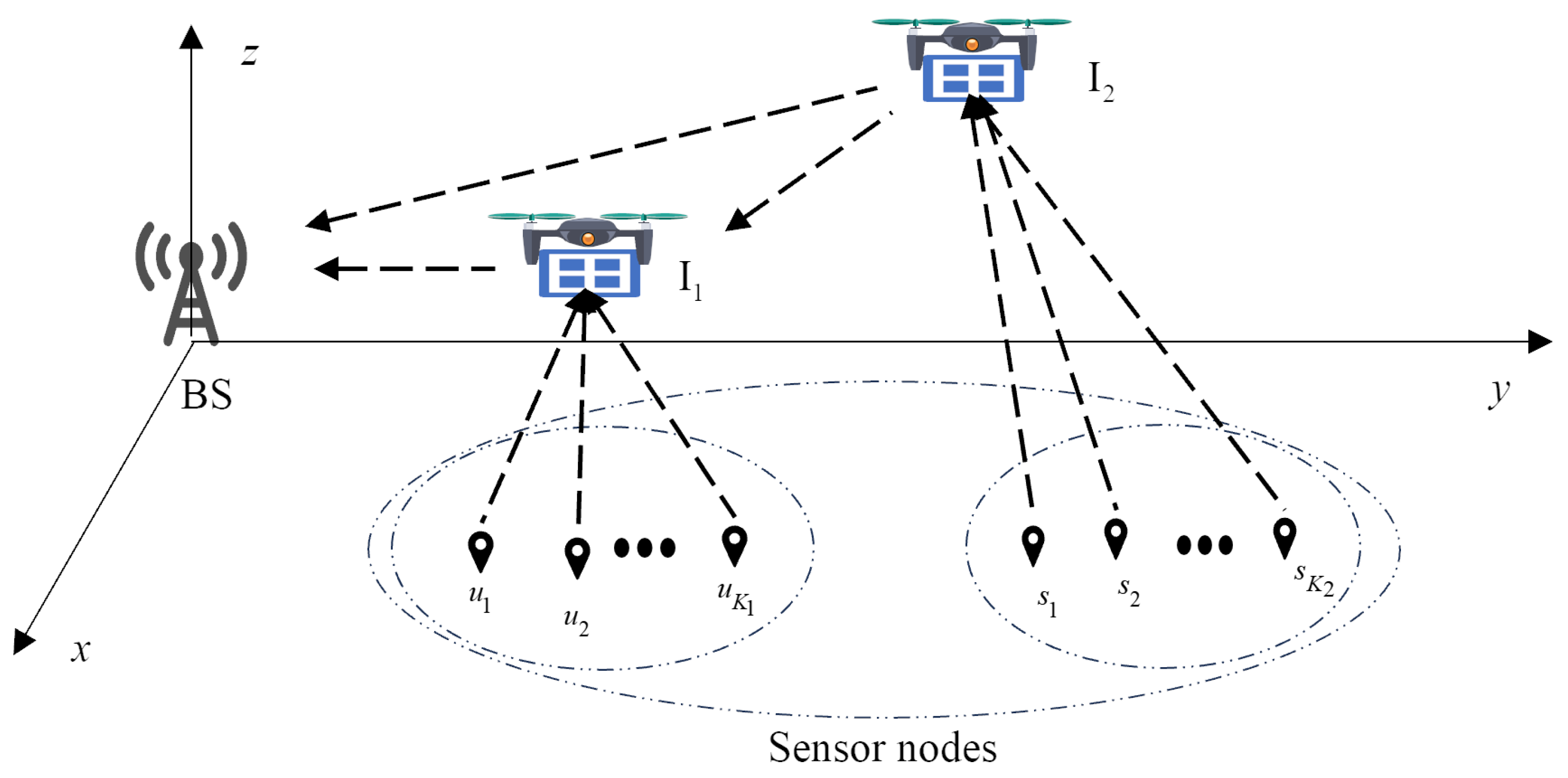
Figure 2.
Trajectories of different schemes.
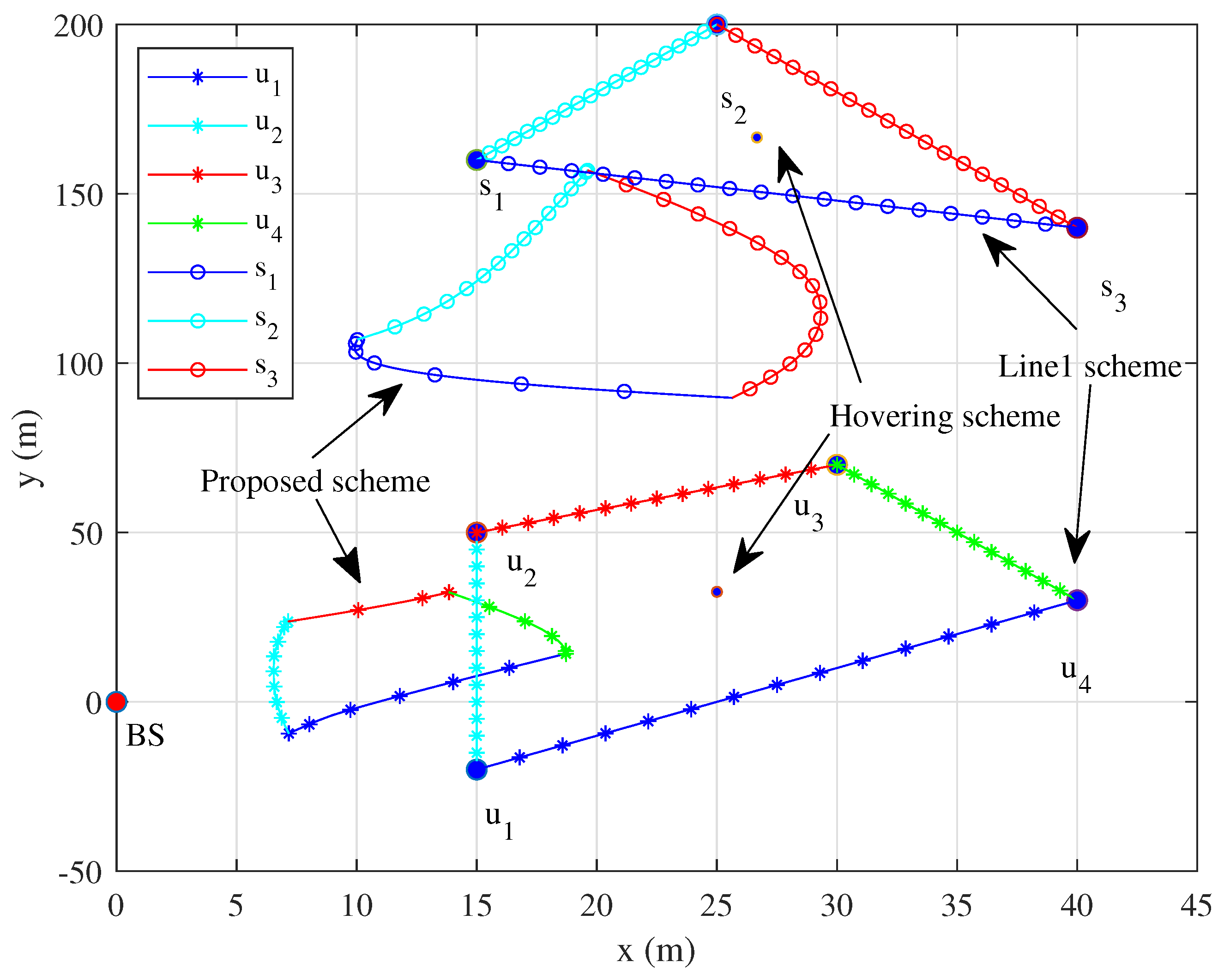
Figure 3.
Comparison of sum rates with different scheme.

Figure 4.
Trajectories under different T.
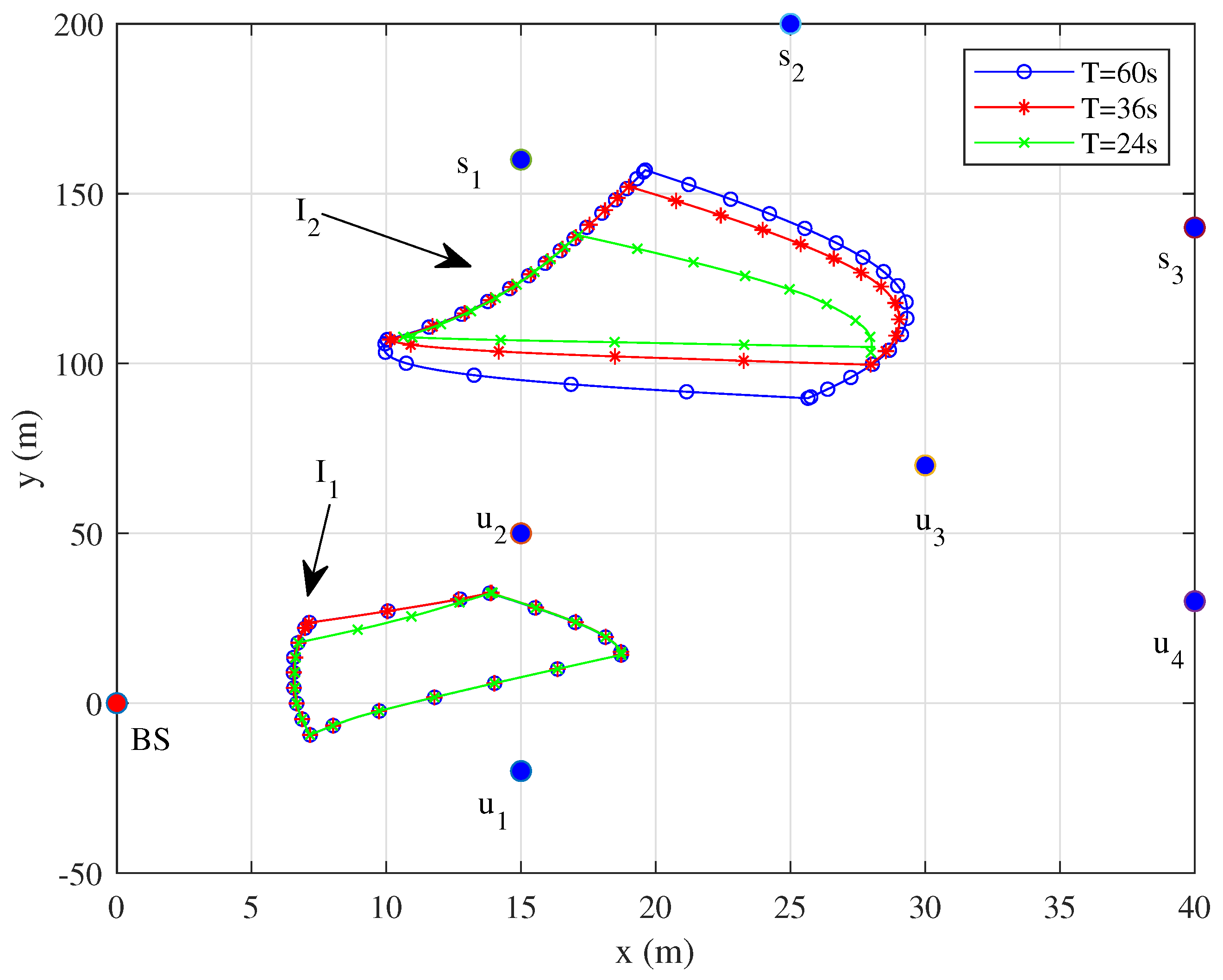
Figure 5.
Speeds of the UAV1 under different T.
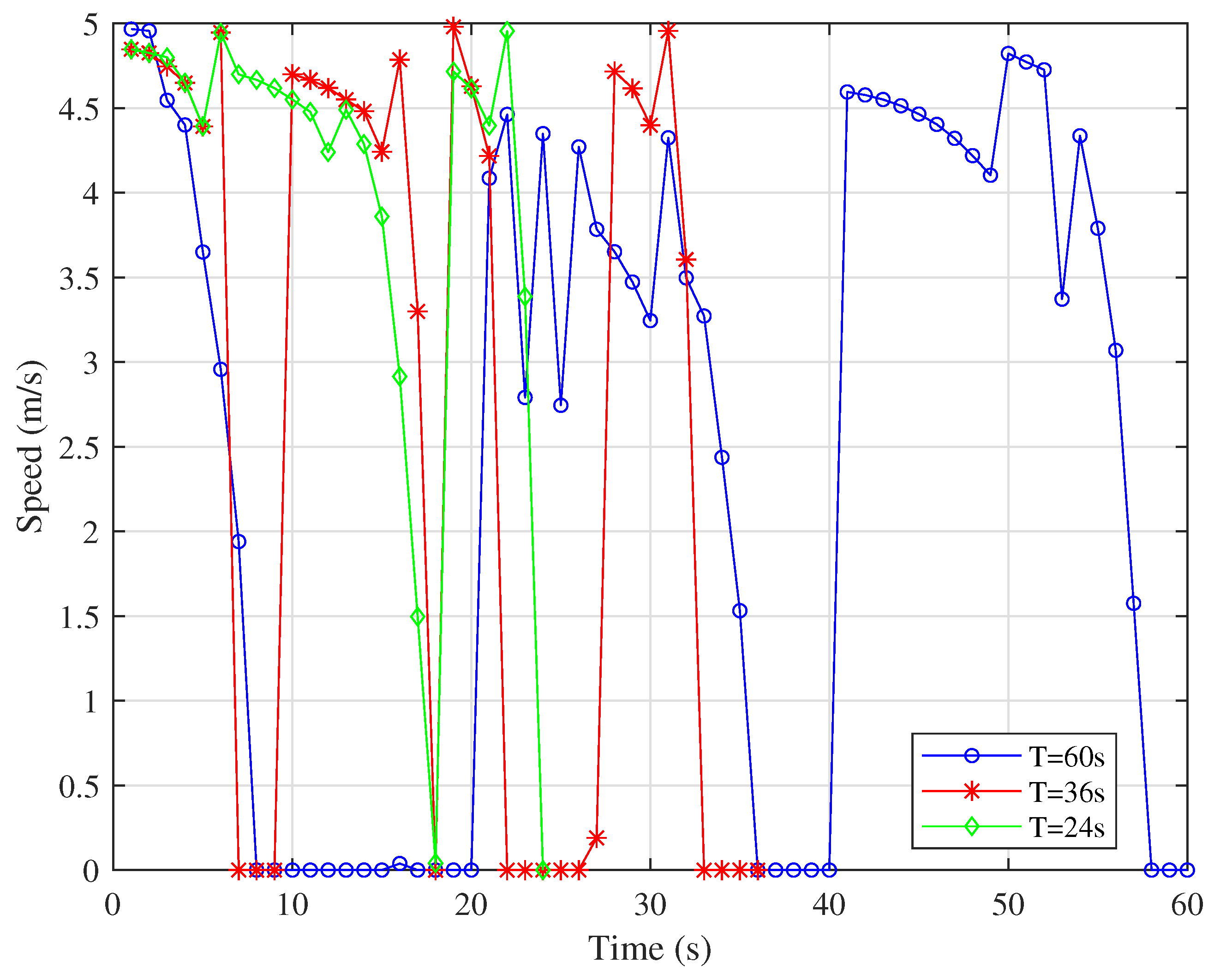
Figure 6.
Speeds of the UAV2 under different T.
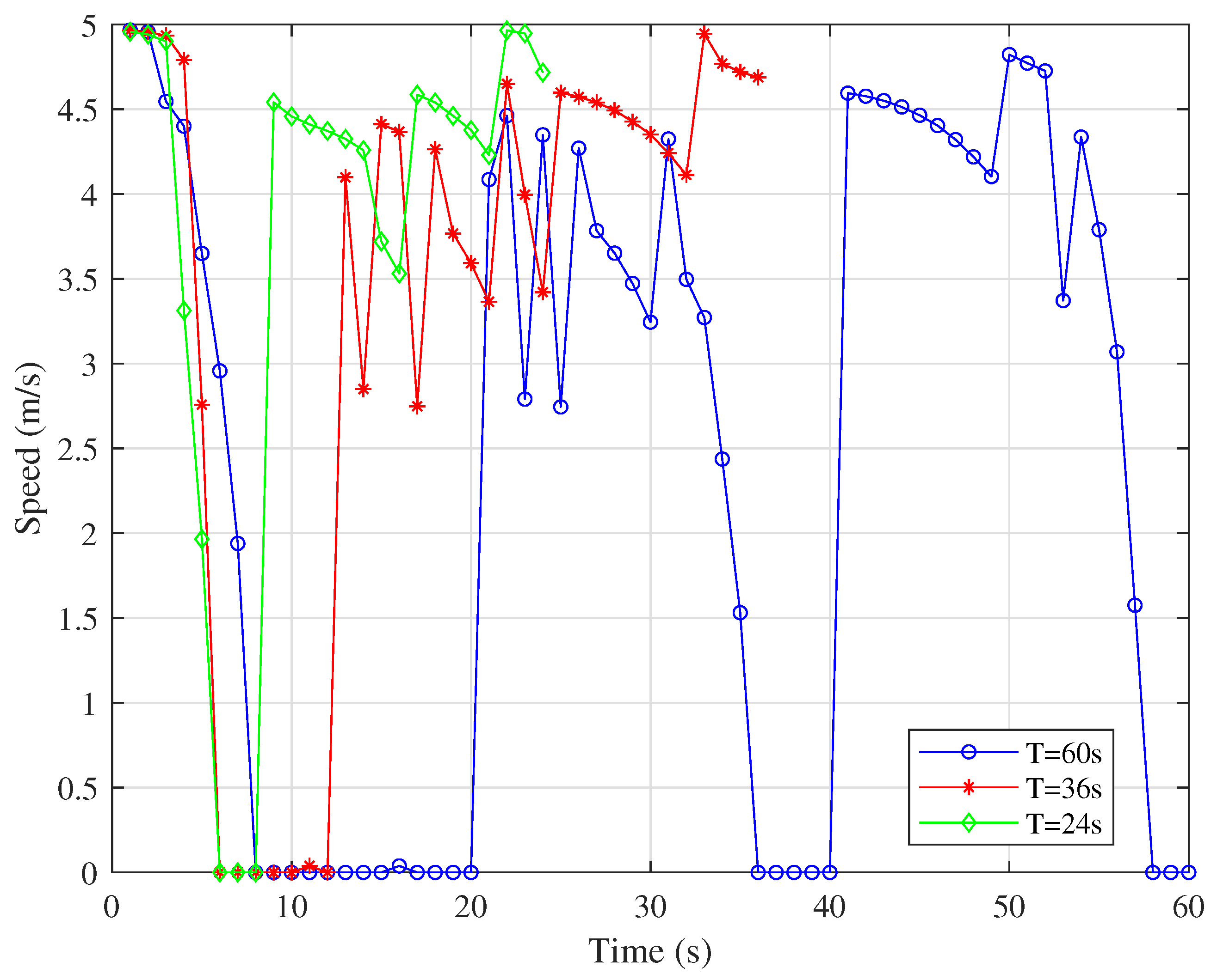
Figure 7.
Trajectories under different .
Disclaimer/Publisher’s Note: The statements, opinions and data contained in all publications are solely those of the individual author(s) and contributor(s) and not of MDPI and/or the editor(s). MDPI and/or the editor(s) disclaim responsibility for any injury to people or property resulting from any ideas, methods, instructions or products referred to in the content. |
© 2025 by the authors. Licensee MDPI, Basel, Switzerland. This article is an open access article distributed under the terms and conditions of the Creative Commons Attribution (CC BY) license (http://creativecommons.org/licenses/by/4.0/).
Copyright: This open access article is published under a Creative Commons CC BY 4.0 license, which permit the free download, distribution, and reuse, provided that the author and preprint are cited in any reuse.


