
Submitted:
28 August 2025
Posted:
01 September 2025
You are already at the latest version
Abstract
The superconducting properties of YBa2Cu3O7−δ thin-films were investigated by conducting 1.7 MeV proton irradiations with a total fluence of 2.64×10¹⁷p/cm2. The superconducting critical temperature (Tc) was reduced from 89.4 K to 10.1 K. The experimental procedure was similar to the previous study (0.6 MeV proton irradiation). We compared the effectiveness of Tc suppression by varying the proton energy from 0.6 to 1.7 MeV and found that in general both protons of 1.7 MeV and 0.6 MeV were effective in suppressing the Tc of YBCO. In particular, both results were consistent with the theoretical expectation (extended d-wave AG theory) when the zero-temperature London penetration depth (λ0) = 215 nm is assumed for thin-film YBCO. For heavily irradiated cases (more than 80% Tc suppression), however, 1.7 MeV protons were more effective in suppressing Tc than 0.6 MeV protons. This can be understood by the fact that in thin-film limit, higher energy protons tend to produce less clustered point-defects while lower energy protons tend to create agglomeration of point-defects.
Keywords:
high-temperature superconductor
; Cuprates
; YBCO
; thin-film
; proton irradiation
; disorders
; resistivity
; Abrikosov-Gor’kov theory
; d-wave
1. Introduction
The discovery of superconductivity in cuprate compounds in 1986 opened a new era of high-temperature superconductivity [1,2]. Due to their exceptional properties (high-, , and ), they became important materials for novel technologies [3,4]. Among them, YBa2Cu3 (YBCO) is one of the most studied compounds. While its Cooper pairing mechanism still remains under debate, it is widely accepted that the optimally-doped YBCO has wave pairing symmetry where the energy gap vanishes in nodal directions [5].
There are many different ways to investigate the pairing symmetry of a superconductor. One of the effective methods is to introduce artificial disorders into the crystal structure of the superconductor and study the response of its superconducting properties. According to Anderson’s theorem, non-magnetic disorders are not effective in suppressing superconductivity of isotropic s-wave superconductors [6]. However, magnetic disorders are effective in suppressing the superconductivity of s-wave superconductors (so-called the Abrikosov-Gor’kov theory, or AG theory) [7]. In an anisotropic d-wave superconductor such as YBCO, non-magnetic disorders are also effective in suppressing the superconductivity [8]. Openov et al. developed a generalized AG theory to explain the effect of non-magnetic disorders on the property of d-wave superconductors [9].
Experimental confirmations of the generalized AG theory have been conducted through high-energy particle irradiation. Different types of particles generate different forms of defects [10]. Electron irradiation has been known to be most effective in the generation of point-like atomic-scale defects due to its low rest mass, resulting in a rapid suppression of superconductivity [11,12,13,14]. Other particles, such as protons and heavy ions, have previously been shown to be effective in creating cascading or columnar defects which have been known to be significantly less effective in suppressing superconductivity [15,16,17,18]. However, neither of these results (electron or others) successfully reproduced the theoretical expectations (generalized d-wave AG theory). Some results have reproduced similar behavior, but rely on a more qualitative analysis rather than direct quantitative agreement. These results were explained in terms of different quality of each sample, different plasma frequencies [8,19], different ratio between in-plane and out-of-plane defects [20], and different electron correlation [21,22,23]. In our previous study, we conducted 0.6 MeV proton irradiation of a thin-film YBCO superconductor using Hope College’s particle accelerator (1.7 MV tandem Van de Graaff electrostatic accelerator) [24]. This experiment produced the results that are quantitatively closer to the theoretical expectation than any previous results. Therefore, we concluded that as the sample thickness approached the thin-film limit, the cascading defects produced by proton irradiation would become negligible, and the atomic point-like defects would dominate.
In this article, we conducted higher energy (1.7 MeV) proton irradiation in a YBCO thin-film superconductor and compared the result with the previous 0.6 MeV experiment. We found that in general, both 1.7 MeV and 0.6 MeV protons were equally effective in suppressing the superconductivity except for the most heavily irradiated cases (more than 80% suppression). For the most heavily irradiated cases, the 1.7 MeV proton was more effective in suppressing than the 0.6 MeV proton, indicating that the 0.6 MeV proton is more prone to create agglomeration of point defects than 1.7 MeV. Furthermore, we found that both results are consistent with the theoretical expectation when the larger London penetration depth value ( = 215 nm) was assumed for thin-film YBCO superconductors.
2. Material and Methods
2.1. YBCO Thin-Film and Resistance Measurements
The YBCO thin-film (≈567 nm thick) was epitaxially grown on a lanthanum aluminate (LaAlO3, or LAO) substrate. The sample was originally fabricated as resonators in commercial microwave filters for wireless base stations [25]. This thin-film sample shows ≈ 89.4 K, indicating that its superconducting property is close to the bulk single-crystalline sample of ≈ 93 K [2]. This sample is of the same batch as the previous study with 0.6 MeV proton irradiation [24].
The in-plane resistance of the YBCO thin-film was measured using a standard four-probe technique as shown in Figure 1. The dimensions of the measured part of the sample are 1.835 (± 0.014) mm × 0.263 (± 0.0008) mm × 566.7 (± 1.9) nm. Four electrical contacts made of fine gold wires were adhered to the thin film using silver paste.
2.2. Energy Degrader and Homogeneous Proton Beam
The proton beam was produced by Hope College’s particle accelerator (1.7 MV tandem Van de Graaff electrostatic accelerator) which is capable of generating proton beams of up to 3.4 MeV kinetic energy. The irradiation was performed at torr at room temperature. This irradiation was conducted along the c-axis of the YBCO sample. 1.7 MeV proton beam was generated by using a 50 m-thick aluminum energy degrader. Using SRIM calculation as shown in Figure 2, we confirmed that if a 2.85 MeV beam passes through a degrader of this thickness, the beam on our target would be 1.7 MeV. This degrader was held in place under the stainless-steel (SS) irradiation shield which shielded the entire sample from irradiation besides a 0.5 mm slit on the target area as seen in Figure 1(a-c). We tuned the beam to a 2 mm diameter beam spot on the Mylar strip atop the sample mount and the quadrupole magnets. We checked that this beam was homogeneous by capturing images of the beam spot and performing an intensity analysis. We tuned the beam until the intensity of the scintillator image was approximately 2 mm across with an even peak. We calibrated the image using the 2 mm by 2 mm square next to the Mylar scintillator as seen in Figure 1(b). This careful calibration was essential to ensuring a homogeneous proton beam. The irradiation was divided into 30-minute increments, during which we would measure the beam current and check the homogeneity of the beam. Using these current calculations, we estimated the fluences on target as shown in the results. The current on target was kept to about 10 nA to avoid sample heating. During irradiation, we experienced some charge buildup issue in the sample. This resulted in fractures occurring along the silver paste line in the YBCO, which destroys the sample. We avoided this effect by grounding four electrical contacts to the metallic sample holder during the irradiation, which eliminated the rapid charge buildup and discharging issue.
3. Results and Discussion
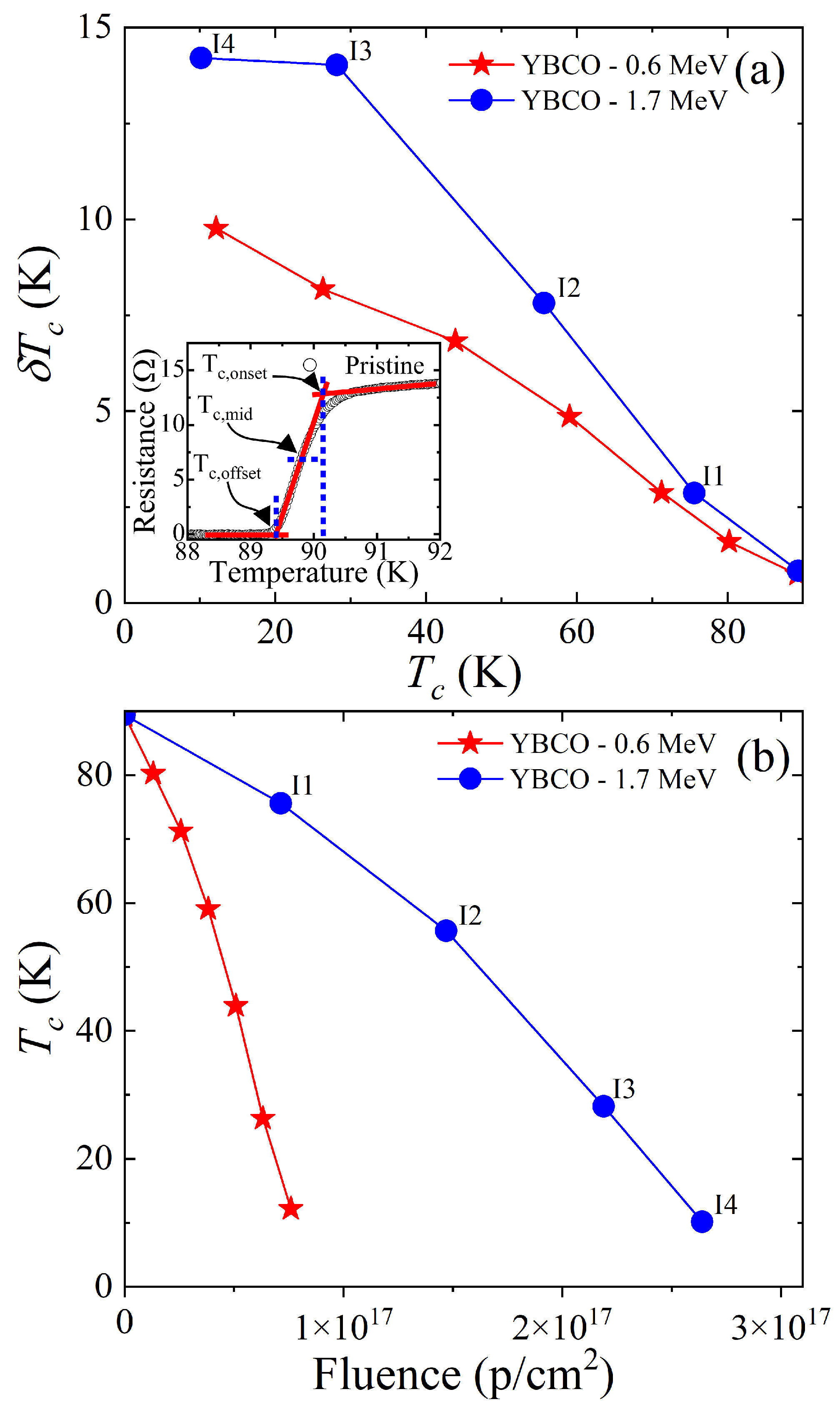
Five resistance measurements and four 1.7 MeV proton irradiations were alternatively conducted in the same YBCO thin-film. The measured resistance is plotted in Figure 3 (a) in comparison to the previous study of 0.6 MeV proton irradiations (Figure 3 (b)). All of these data show two superconducting transitions except for the pristine cases. These double transitions occur since only part of the area in which the resistance was measured was irradiated as described in Figure 1 (d). The of the unirradiated part does not change while the of the irradiated part decreases with increasing fluence. The normal state resistance above linearly increases upon irradiation following Matthiessen’s rule. This increase indicates that the number of defects in the irradiated part of the sample increases gradually upon irradiation. The rate of suppression with respect to the fluence is about three times larger for 0.6 MeV proton irradiation than for 1.7 MeV proton irradiation (Figure 4(b)). This is because as we increase the energy of the proton beam, we simultaneously increase the implantation depth. The greater implantation depth means the less energy per proton is deposited into our thin-film sample. As shown in Figure 2(b), it is evident that the number of defects created in the thin-film YBCO sample is about three times smaller for 1.7 MeV protons than for 0.6 MeV protons. This is consistent with the fact that 1.7 MeV proton irradiation needs about three times more fluence than 0.6 MeV proton irradiation to achieve the similar suppression as shown in Figure 4 (b). Figure 4(a) shows the broadening of superconducting transition upon irradiation. This broadening is caused by the spacing between aluminum energy degrader and the thin-film surface being about 0.5 - 0.7 mm. In the future, we plan to redesign the sample holder to decrease this spacing to 0.2 mm in order to minimize the broadening effect.
The increase in normal-state resistance is caused by the resistance increase in the irradiated part of the sample. Thus, we can convert the resistance increase to the resistivity increase by considering the volume of the irradiated part of the sample. Because the normal state resistance increases linearly across all temperature regions above the superconducting transition, the resistance value at 125 K was chosen to calculate the resistivity increase ().
According to Openov [19], the generalized AG theory for the case of the non-magnetic disorders in d-wave superconductors can be written as follows,
where is /, is the initial before the disorders are added, and g is the dimensionless scattering rate. asymptotically goes to zero as g approaches 0.28. Using the Drude model [28,29], g can also be written in terms of the residual resistivity () as follows,
where is the residual resistivity at T = 0 K of the irradiated part of the YBCO sample, is the critical temperature of the pristine sample, and is the zero-temperature London penetration depth of the pristine sample. Due to the high of the YBCO sample, it is difficult to estimate the exact residual resistivity. If the normal state residual resistivity is very small, in Eq. 2 can be replaced by . Indeed, the linear approximation of normal state resistivity in our previous study [24] suggests very small residual resistivity at T = 0 K (≈ 8 ) and the current YBCO sample is almost identical to the previous sample as shown in Figure 7. By replacing in Eq. 2 with , g can be rewritten as follows,
where is the resistivity increase at T = 125 K of the irradiated part of the YBCO sample. This calculation requires a value for the London penetration depth, which we are not able to measure in our lab. Therefore, we surveyed experimental values of from the previous studies, such as Å [30], 1550 Å [31], Å [32], and 2150 Å [33]. Among them, we used 2150 Å [33] for thin-film single-crystalline YBCO samples and Å [34] for bulk single-crystalline YBCO samples in Figure 6. The YBCO single-crystallined thin-films on LAO substrate are structurally less perfect than YBCO bulk single crystals. Therefore, strong scattering of the charge carriers, characterized by the mean-free path (l), is expected to extend the penetration depth in thin-film samples similar to that predicted by Tinkham [35] for “dirty" superconductors. Thus, large of 215 nm is reasonable for thin-film samples. For the purpose of comparison, we used both London penetration depth values of 140.5 nm and 215 nm to plot our results in Figure 5. When = 215 nm is used, both 1.7 MeV and 0.6 MeV results closely follow the theoretical expectation. However,the heavily irradiated results (more than 80% suppression) start deviating from the theoretical expectation. This indicates a development of extended defects where the nearby point defects agglomerate at high fluence as mentioned by Wu et al. [15]. For the most heavily irradiated cases, furthermore, suppression upon 0.6 MeV proton irradiation is not as effective as 1.7 MeV proton irradiation. It suggests that lower-energy protons are prone to create a cluster of point defects even in the thin-film limit than the higher-energy protons.
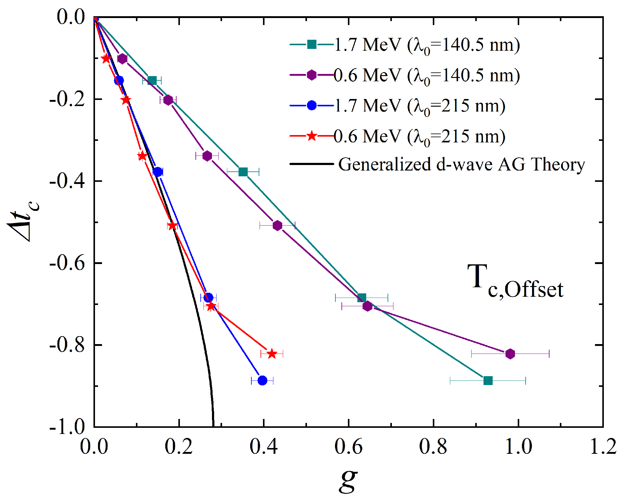
Figure 5.
Normalized () as a function of g (dimensionless scattering rate) upon 1.7 MeV and 0.6 MeV proton irradiation. Since g depends on the London penetration depth (), we used two values commonly used for bulk single-crystalline (140.5 nm) and thin-film YBCO (214 nm). When = 215 nm is used, both 1.7 and 0.6 MeV proton irradiation results closely follow the theoretical expectation. For the heavily irradiated cases (more than 60 % suppression), both results start deviating from the theoretical expectation. Particularly for the most heavily irradiated cases (more than 80 % suppression) there is a clear difference between 1.7 MeV and 0.6 MeV irradiation.
It is evident that the agglomeration is more significant in 0.6 MeV proton irradiation than 1.7 MeV proton irradiation.
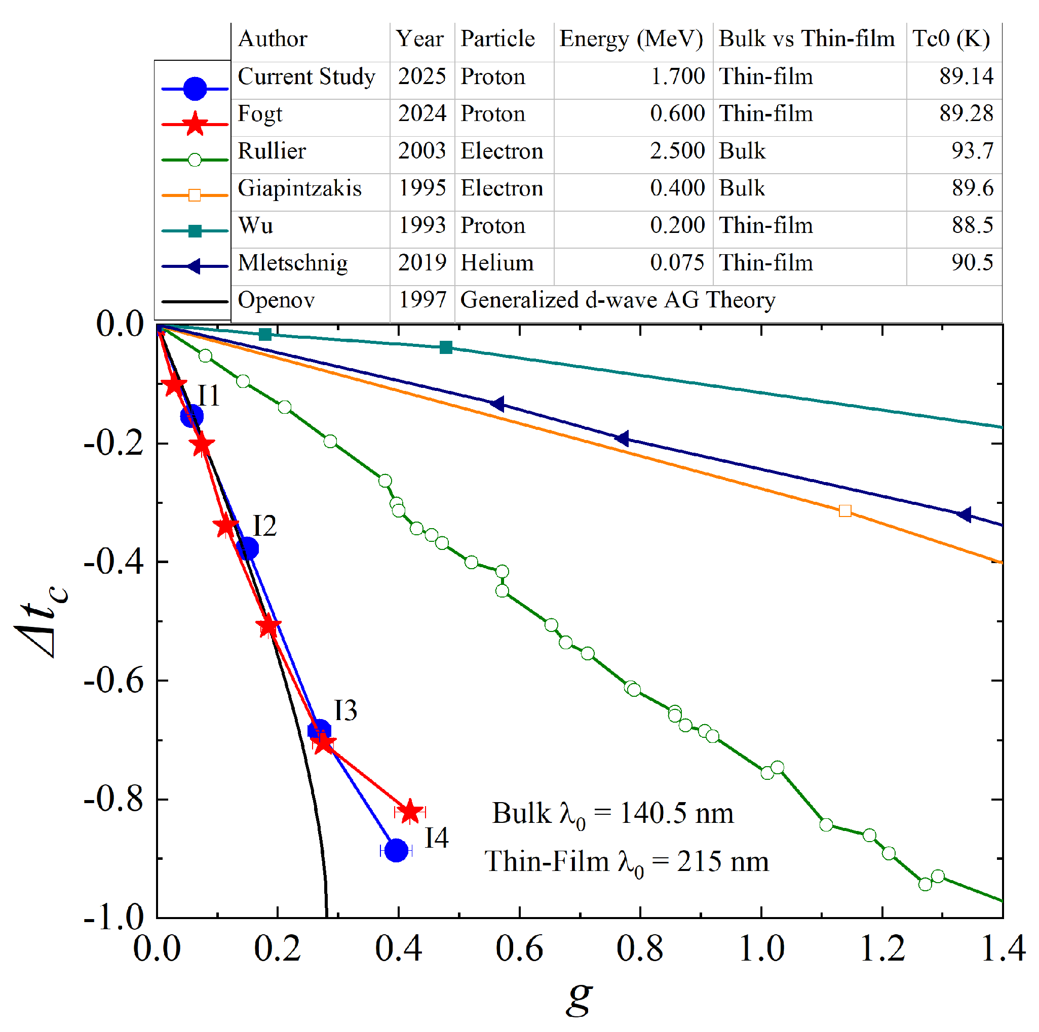
Figure 6 compares the relation between and g of the current study with previous irradiation studies [10,11,12,15,24] and theoretical expectation [19]. Note that different penetration depth values are used for bulk single crystals and thin-film single crystals. The current proton irradiation study is the one that most agrees with the theoretical expectation. In particular, it is surprising that the current proton irradiation is more effective in suppressing superconductivity than the electron irradiation. This can be partially understood that the dominant form of defects caused by proton irradiations shifts from cascade defects to atomic-size point-defects as the sample thickness reaches the thin-film limit; i.e., the implantation depth of the proton becomes much longer relative to the sample thickness. However, further investigation is needed to fully understand it.
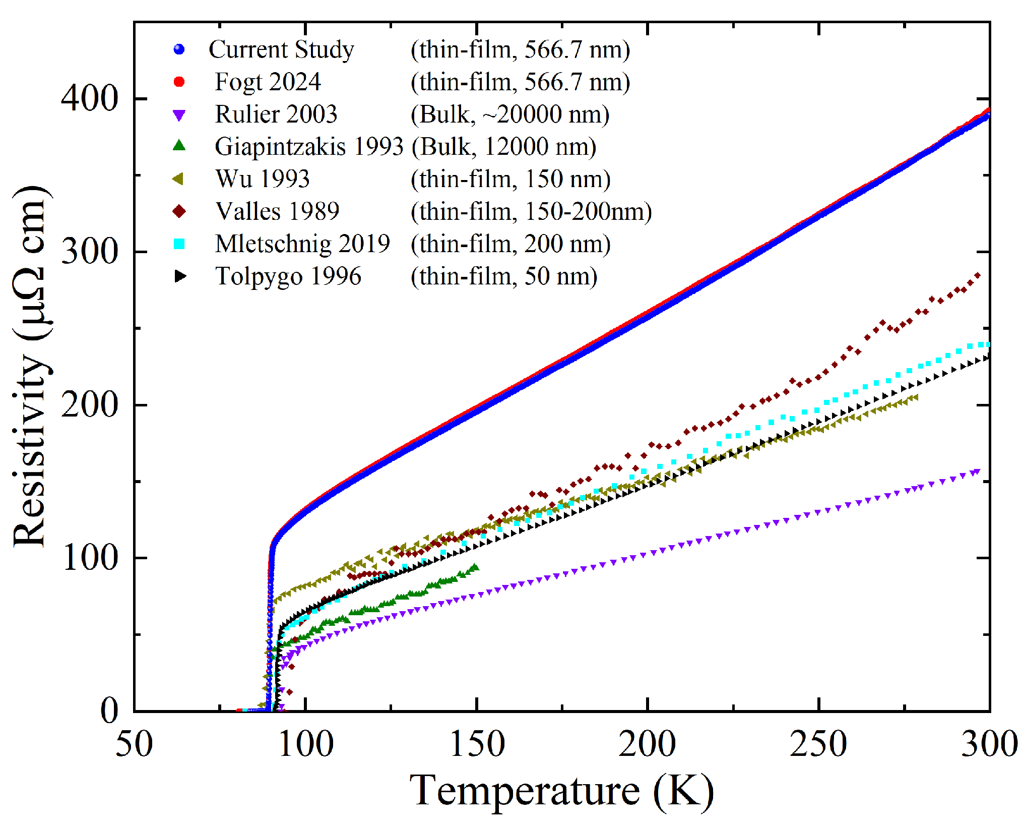
Figure 7.
The pristine resistivity of the 0.6 MeV and 1.7 MeV samples. There is little to no difference in the sample resistivity indicating the samples are nearly identical. Normal state resistivity is higher in the current YBCO study than previous studies.
Figure 7.
The pristine resistivity of the 0.6 MeV and 1.7 MeV samples. There is little to no difference in the sample resistivity indicating the samples are nearly identical. Normal state resistivity is higher in the current YBCO study than previous studies.
4. Conclusions
We conducted 1.7 MeV proton irradiation in a YBCO thin film and compared the result with the previous study (0.6 MeV proton irradiation). We found that both 1.7 MeV and 0.6 MeV irradiations were effective in suppressing superconductivity. For the most heavily irradiated cases (more than 80 % suppression), 0.6 MeV irradiation was less effective in suppressing the superconductivity than 1.7 MeV. This indicates that 0.6 MeV irradiation produced more agglomeration of point-defects for the heavily irradiated cases. Furthermore, when = 215 nm is assumed, both 1.7 MeV and 0.6 MeV results were consistent with the theoretical expectation except for the most heavily irradiated cases.
Author Contributions
Conceptualization and sample preparation, K.Cho; proton irradiation and resistance measurement, T.H., J.K. K.Cook, H.W., J.F., and N.M.; data analysis and calculation, T.H., J.K. K.Cook, H.W., J.F., and N.M.; writing—original draft preparation and review, T.H., J.K. K.Cook, H.W., J.F., N.M., K.Cho. All authors have read and agreed to the published version of the manuscript.
Funding
The laboratory facilities are supported by the National Science Foundation under grants NSF PHYS-0319523 and PHYS-2209138. The research reported in this publication was supported in part by funding provided by the National Aeronautics and Space Administration (NASA), under award number 80NSSC20M0124, Michigan Space Grant Consortium (MSGC).
Data Availability Statement
The data presented in this study are available on reasonable request from the corresponding author.
Acknowledgments
We thank Paul DeYoung and Andrew Bunnell for assisting us in operating the particle accelerator. We thank David Daugherty for assisting us in designing new sample mounts. We thank Stephen Remillard for providing YBCO samples.
Conflicts of Interest
The authors declare no conflicts of interest.
References
- Bednorz, J.G.; Mueller, K.A. Possible high Tc superconductivity in the barium-lanthanum-copper-oxygen system. Z. Phys. B: Condens. Matter 1986, 64, 189–93. [Google Scholar] [CrossRef]
- Wu, M.K.; Ashburn, J.R.; Torng, C.J.; Hor, P.H.; Meng, R.L.; Gao, L.; Huang, Z.J.; Wang, Y.Q.; Chu, C.W. Superconductivity at 93 K in a new mixed-phase Y-Ba-Cu-O compound system at ambient pressure. Phys. Rev. Lett. 1987, 58, 908–910. [Google Scholar] [CrossRef] [PubMed]
- Hahn, S.; Kim, K.; Kim, K.; Hu, X.; Painter, T.; Dixon, I.; Kim, S.; Bhattarai, K.R.; Noguchi, S.; Jaroszynski, J.; et al. 45.5-tesla direct-current magnetic field generated with a high-temperature superconducting magnet. Nature 2019, 570, 496–499. [Google Scholar] [CrossRef] [PubMed]
- Molodyk, A.; Samoilenkov, S.; Markelov, A.; Degtyarenko, P.; Lee, S.; Petrykin, V.; Gaifullin, M.; Mankevich, A.; Vavilov, A.; Sorbom, B.; et al. Development and large volume production of extremely high current density YBa2Cu3O7 superconducting wires for fusion. Scientific Reports 2021, 11, 2084. [Google Scholar] [CrossRef]
- Tsuei, C.C.; Kirtley, J.R. Pairing symmetry in cuprate superconductors. Rev. Mod. Phys. 2000, 72, 969–1016. [Google Scholar] [CrossRef]
- Anderson, P.W. Theory of dirty superconductors. Journal of Physics and Chemistry of Solids 1959, 11, 26–30. [Google Scholar] [CrossRef]
- Abrikosov, A.A.; Gor’kov, L.P. Contribution to the theory of superconducting alloys with paramagnetic impurities. Zh. Eksp. Teor. Fiz. (Sov. Phys. JETP 12, 1243 (1961)) 1960, 39, 1781. [Google Scholar]
- Radtke, R.J.; Levin, K.; Schüttler, H.B.; Norman, M.R. Predictions for impurity-induced Tc suppression in the high-temperature superconductors. Phys. Rev. B 1993, 48, 653–656. [Google Scholar] [CrossRef]
- Openov, L.A. Combined effect of nonmagnetic and magnetic scatterers on the critical temperatures of superconductors with different anisotropies of the gap. Journal of Experimental and Theoretical Physics Letters 1997, 66, 661–667. [Google Scholar] [CrossRef]
- Mletschnig, K.; Lang, W. Nano-patterning of cuprate superconductors by masked He+ ion irradiation: 3-dimensional profiles of the local critical temperature. Microelectronic Engineering 2019, 215, 110982. [Google Scholar] [CrossRef]
- Rullier-Albenque, F.; Alloul, H.; Tourbot, R. Influence of Pair Breaking and Phase Fluctuations on Disordered High Tc Cuprate Superconductors. Phys. Rev. Lett. 2003, 91, 047001. [Google Scholar] [CrossRef] [PubMed]
- Giapintzakis, J.; Ginsberg, D.M.; Kirk, M.A. Determination of the symmetry of the superconducting pairing state and formation of a low-temperature normal metallic state in YBCO by electron irradiation. Technical Report 1995. [Google Scholar] [CrossRef]
- Cho, K.; Kończykowski, M.; Teknowijoyo, S.; Tanatar, M.A.; Liu, Y.; Lograsso, T.A.; Straszheim, W.E.; Mishra, V.; Maiti, S.; Hirschfeld, P.J.; et al. Energy gap evolution across the superconductivity dome in single crystals of Ba1-xKxFe2As2. Science Advances 2016, 2, e1600807. [Google Scholar] [CrossRef] [PubMed]
- Cho, K.; Kończykowski, M.; Teknowijoyo, S.; Ghimire, S.; Tanatar, M.A.; Mishra, V.; Prozorov, R. Intermediate scattering potential strength in electron-irradiated YBa2Cu3O7-δ from London penetration depth measurements. Phys. Rev. B 2022, 105, 014514. [Google Scholar] [CrossRef]
- Wu, J.Z.; Yu, N.; Chu, W.K. Anisotropy of the ion-beam radiation effect in YBa2Cu3O7-δ (110) thin films. Phys. Rev. B 1993, 48, 9929–9931. [Google Scholar] [CrossRef]
- Torsello, D.; Fracasso, M.; Gerbaldo, R.; Ghigo, G.; Laviano, F.; Napolitano, A.; Iebole, M.; Cialone, M.; Manca, N.; Martinelli, A.; et al. Proton Irradiation Effects on the Superconducting Properties of Fe(Se,Te) Thin Films. IEEE Transactions on Applied Superconductivity 2022, 32, 1–5. [Google Scholar] [CrossRef]
- Konczykowski, M.; Rullier-Albenque, F.; Yacoby, E.R.; Shaulov, A.; Yeshurun, Y.; Lejay, P. Effect of 5.3-GeV Pb-ion irradiation on irreversible magnetization in Y-Ba-Cu-O crystals. Phys. Rev. B 1991, 44, 7167–7170. [Google Scholar] [CrossRef]
- Nakajima, Y.; Tsuchiya, Y.; Taen, T.; Tamegai, T.; Okayasu, S.; Sasase, M. Enhancement of critical current density in Co-doped BaFe2As2 with columnar defects introduced by heavy-ion irradiation. Phys. Rev. B 2009, 80, 012510. [Google Scholar] [CrossRef]
- Openov, L.A. Critical temperature of an anisotropic superconductor containing both nonmagnetic and magnetic impurities. Phys. Rev. B 1998, 58, 9468–9478. [Google Scholar] [CrossRef]
- Graser, S.; Hirschfeld, P.J.; Zhu, L.Y.; Dahm, T. Tc suppression and resistivity in cuprates with out of plane defects. Phys. Rev. B 2007, 76, 054516. [Google Scholar] [CrossRef]
- Garg, A.; Randeria, M.; Trivedi, N. Strong correlations make high-temperature superconductors robust against disorder. Nature Physics 2008, 4, 762–765. [Google Scholar] [CrossRef]
- Kemper, A.F.; Doluweera, D.G.S.P.; Maier, T.A.; Jarrell, M.; Hirschfeld, P.J.; Cheng, H.P. Insensitivity of d-wave pairing to disorder in the high-temperature cuprate superconductors. Phys. Rev. B 2009, 79, 104502. [Google Scholar] [CrossRef]
- Tang, S.; Dobrosavljević, V.; Miranda, E. Strong correlations generically protect d-wave superconductivity against disorder. Phys. Rev. B 2016, 93, 195109. [Google Scholar] [CrossRef]
- Fogt, J.; Weeda, H.; Harrison, T.; Miles, N.; Cho, K. Effect of Proton Irradiation on Thin-Film YBa2Cu3O7 Superconductor. Materials 2024, 17, 4601. [Google Scholar] [CrossRef] [PubMed]
- Remillard, S.K.; Kirkendall, D.; Ghigo, G.; Gerbaldo, R.; Gozzelino, L.; Laviano, F.; Yang, Z.; Mendelsohn, N.A.; Ghamsari, B.G.; Friedman, B.; et al. Microwave nonlinearity and photoresponse of superconducting resonators with columnar defect micro-channels. Superconductor Science and Technology 2014, 27, 095006. [Google Scholar] [CrossRef]
- Ziegler, J.F.; Ziegler, M.; Biersack, J. SRIM– The stopping and range of ions in matter. Nuclear Instruments and Methods in Physics Research B 268, 1818–1823. [CrossRef]
- Miles, N.; Fogt, J.; Harrison, T.; Weeda, H.; Bunnell, A.; A. DeYoung, P.; Cho, K. Correcting Faraday Cup Measurements with Rutherford Backscattering Spectroscopy. Journal of Undergraduate Research in Physics and Astronomy 2025, xx, xxxxx. [Google Scholar]
- Prozorov, R.; Kończykowski, M.; Tanatar, M.A.; Thaler, A.; Bud’ko, S.L.; Canfield, P.C.; Mishra, V.; Hirschfeld, P.J. Effect of Electron Irradiation on Superconductivity in Single Crystals of Ba(Fe1-xRux)2As2 (x=0.24). Phys. Rev. X 2014, 4, 041032. [Google Scholar] [CrossRef]
- Cho, K.; Kończykowski, M.; Teknowijoyo, S.; Tanatar, M.A.; Prozorov, R. Using electron irradiation to probe iron-based superconductors. Superconductor Science and Technology 2018, 31, 064002. [Google Scholar] [CrossRef]
- Prozorov, R.; Giannetta, R.W.; Carrington, A.; Fournier, P.; Greene, R.L.; Guptasarma, P.; Hinks, D.G.; Banks, A.R. Measurements of the absolute value of the penetration depth in high-Tc superconductors using a low-Tc superconductive coating. Applied Physics Letters 2000, 77, 4202–4204. [Google Scholar] [CrossRef]
- Bernhard, C.; Niedermayer, C.; Binninger, U.; Hofer, A.; Wenger, C.; Tallon, J.L.; Williams, G.V.M.; Ansaldo, E.J.; Budnick, J.I.; Stronach, C.E.; et al. Magnetic penetration depth and condensate density of cuprate high-Tc superconductors determined by muon-spin-rotation experiments. Phys. Rev. B 1995, 52, 10488–10498. [Google Scholar] [CrossRef]
- Djordjevic, S.; de Vaulchier, L.A.; Bontemps, N.; Vieren, J.P.; Guldner, Y.; Moffat, S.; Preston, J.; Castel, X.; Guilloux-Viry, M.; Perrin, A. Low temperature penetration depth and the effect of quasi-particle scattering measured by millimeter wave transmission in YBa2Cu3O7-δ thin films. The European Physical Journal B - Condensed Matter and Complex Systems 1998, 5, 847–858. [Google Scholar] [CrossRef]
- Zaitsev, A.G.; Schneider, R.; Linker, G.; Ratzel, F.; Smithey, R.; Schweiss, P.; Geerk, J.; Schwab, R.; Heidinger, R. Microwave measurements of the absolute London penetration depth in double-sided YBa2Cu3O7—x thin films on sapphire. Review of Scientific Instruments 2002, 73, 335–344. [Google Scholar] [CrossRef]
- Bonn, D.A.; Liang, R.; Riseman, T.M.; Baar, D.J.; Morgan, D.C.; Zhang, K.; Dosanjh, P.; Duty, T.L.; MacFarlane, A.; Morris, G.D.; et al. Microwave determination of the quasiparticle scattering time in YBa2Cu3O6.95. Phys. Rev. B 1993, 47, 11314–11328. [Google Scholar] [CrossRef]
- Tinkham, M. Introduction to Superconductivity; McGraw Hill, 1996.
Figure 1.
YBCO sample mounted in the sample holder. (a) The rectangle on the diagram denotes the section of YBCO that was irradiated. The circle on the diagram indicates the 2 mm diameter beam spot on the sample (b) A stainless steel (SS) beam shield was placed above the sample, reducing the beam width to exactly 0.5 mm. A Mylar scintillator is placed on the beam shield for calibration of the homogeneous 2 mm diameter proton beam. A 50 m Al energy degrader is placed to reduce the beam energy from 2.85 MeV to 1.7 MeV. (c) Side view of the sample holder including the SS beam shield above the YBCO sample, which is grown on the LAO substrate mounted on a sapphire plate. (d) Top view of YBCO sample showing the portions of the unirradiated and irradiated parts of the sample. Proton irradiation is homogeneous in the irradiated section of the sample.
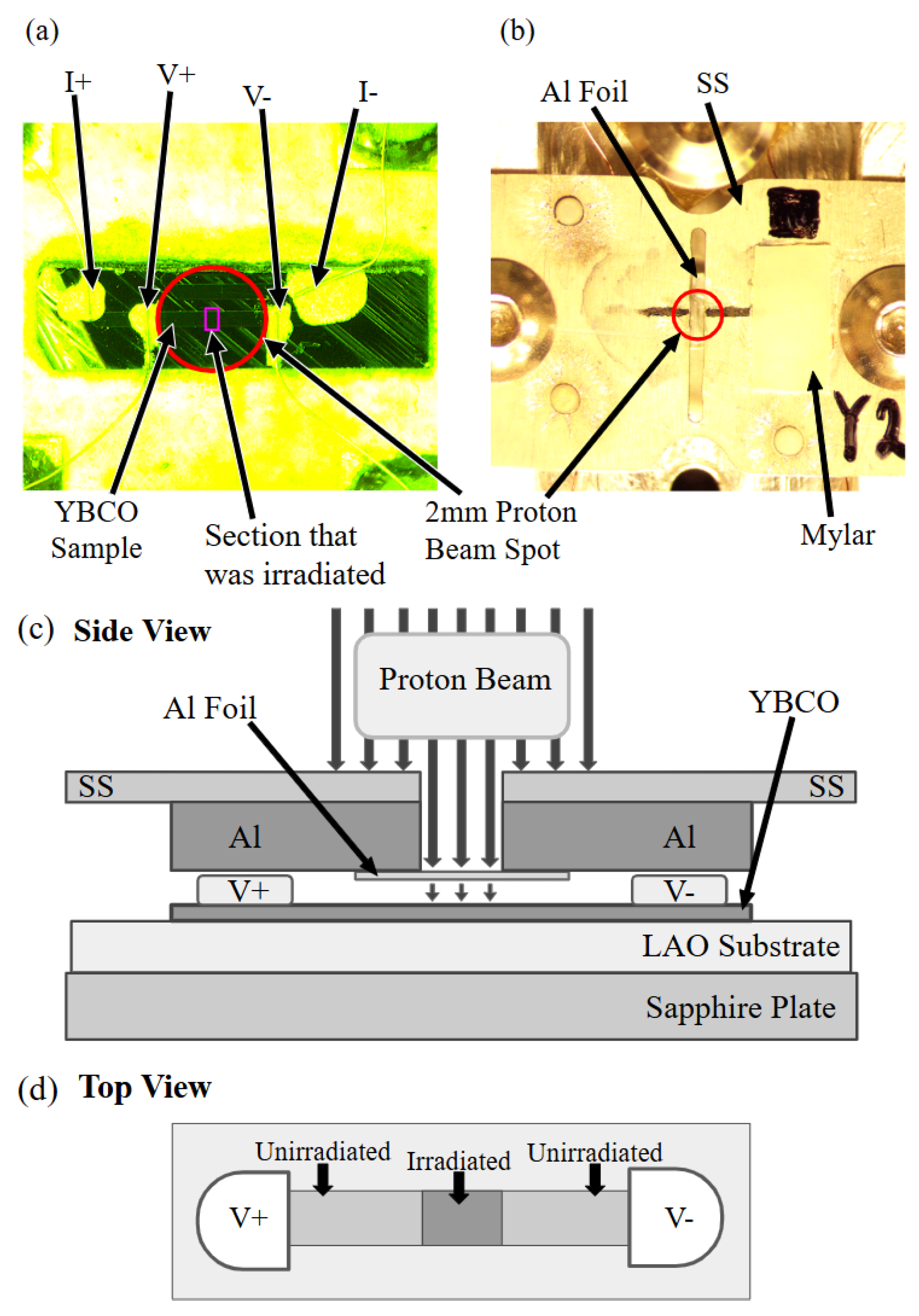
Figure 2.
(a) The proton beam energy before and after the 50 m Al energy degrader. The blue and red dotted lines denote the beam energies of the current (1.7 MeV) and previous experiments (0.6 MeV), respectively. These data are calculated using SRIM simulation [26]. (b) TRIM simulation results that show vacancies-per-ion along depth for 1.7 and 0.6 MeV protons. Implantation depths for 1.7 MeV and 0.6 MeV protons are about 20 m and 4.3 m, respectively. Since thickness of YBCO thin-film is 567 nm, the protons will be implanted into the LAO substrate. From the simulation, it is clear that a 0.6 MeV proton is about three times more effective in creating defects in YBCO thin-film than a 1.7 MeV proton.
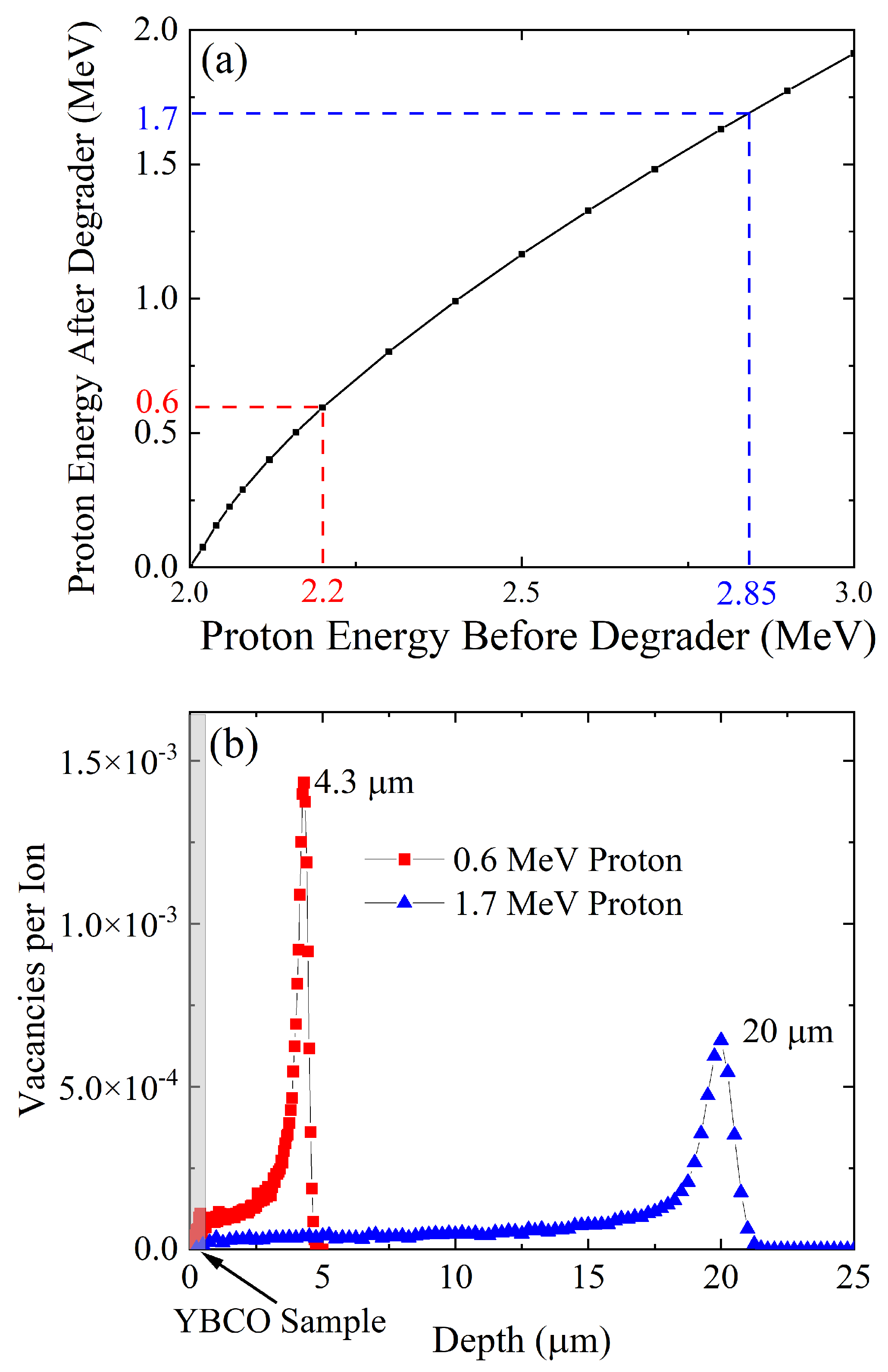
Figure 3.
Temperature-dependent resistance data upon a series of (a) 1.7 MeV and (b) 0.6 MeV proton irradiations. The fluences shown in legends are initially measured by Faraday cup and corrected by using Rutherford-Back-Scattering calibration procedure [27]. For both cases, we see a linear increase in the normal-state resistance upon proton irradiations which is consistent with Matthiessen’s rule.
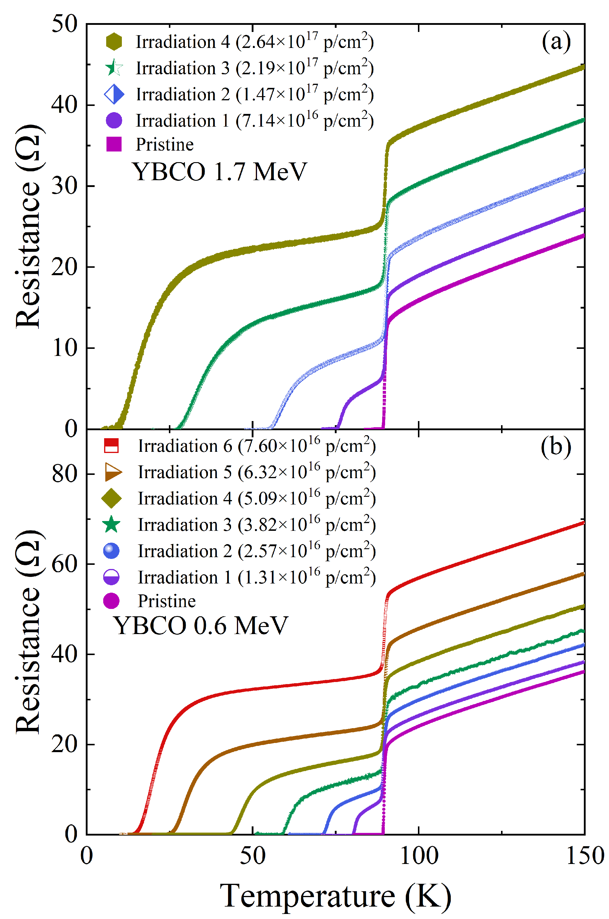
Figure 4.
(a) Broadening of the superconducting transition () for 1.7 MeV and 0.6 MeV proton irradiations. and are defined in the inset. The horizontal axis is the , and the vertical axis is the irradiation’s associated broadening. We see much greater broadening in the 1.7 MeV irradiation. (b) measured for various fluences on 0.6 MeV irradiated and 1.7 MeV irradiated samples. The 1.7 MeV proton beam requires about three times more fluence in order to suppress the superconductivity compared to the 0.6 MeV proton beam. This is consistent with TRIM simulation shown in Figure 2.
Disclaimer/Publisher’s Note: The statements, opinions and data contained in all publications are solely those of the individual author(s) and contributor(s) and not of MDPI and/or the editor(s). MDPI and/or the editor(s) disclaim responsibility for any injury to people or property resulting from any ideas, methods, instructions or products referred to in the content. |
© 2025 by the authors. Licensee MDPI, Basel, Switzerland. This article is an open access article distributed under the terms and conditions of the Creative Commons Attribution (CC BY) license (http://creativecommons.org/licenses/by/4.0/).
Copyright: This open access article is published under a Creative Commons CC BY 4.0 license, which permit the free download, distribution, and reuse, provided that the author and preprint are cited in any reuse.


