
Submitted:
27 August 2025
Posted:
29 August 2025
You are already at the latest version
Abstract
Room temperature self-healing polyurethanes (PUs) generally showed limited mechanical properties. In order to improve the mechanical properties of PUs without sacrificing their self-healing ability, in this study, different amounts of halloysite clay filler were added. Thus, intrinsically self-healing PUs were synthesized using polycar-bonate diol polyol, aliphatic diisocyanate, 1,4-butanediol, and different amounts (0.5–10 wt.%) of thermally treated halloysite. The structural, thermal, viscoelastic, and me-chanical properties of the resulting PU/halloysite composites were evaluated. All hal-loysite-filled PUs retained room-temperature self-healing capability, while exhibiting improved mechanical strength. PU with 0.5 wt.% halloysite (E0.5) showed the most balanced performance, with well-dispersed halloysite nanotubes intercalated within the soft segments, enhancing chain mobility and soft segment ordering. Higher hal-loysite loadings (1–3 wt.%) led to increased mechanical properties but also some round clay particles agglomeration and surface migration; this led to limited halloysite–PU matrix interactions. The addition of more than 3 wt.% halloysite did not result in fur-ther improvements of mechanical properties. The findings of this study provided new insight into the filler–polymer interaction mechanism and establish a foundation for the design of multifunctional PUs with both autonomous self-repair and enhanced mechanical performance.
Keywords:
polyurethane
; intrinsic room temperature self-healing
; halloysite
; polycarbonate diol polyol
; soft segments
; mechanical reinforcement
; filler-matrix interactions
1. Introduction
There is a growing interest in the development of self-healing polymeric materials for innovative applications in biomedical devices, coatings, structural adhesives, and flexible electronics, applications in which long-term durability and damage tolerance are critical. Self-healing polyurethanes (PUs) are very versatile materials due to their adaptable chemical architecture, mechanical properties, and thermal stability [1,2].
PUs are typically synthesized via polyaddition reactions between polyols and diisocyanates, sometimes incorporating chain extenders. Their structure consists of alternating soft and hard segments. The soft segments are formed by high-molecular-weight polyol, which impart elasticity and chain mobility; the hard segments result from the reaction of isocyanates with low-molecular-weight diols or diamines, and provide mechanical strength [3-6]. Due to the inherent polarity contrast between these segments, micro-phase separation occurs during PU synthesis. This phase-segregated morphology leads to amorphous or semi-crystalline hard domains dispersed in a soft, flexible matrix (Figure 1). The resulting architecture offers a unique combination of flexibility and structural integrity, with the hard domains acting as reversible physical crosslinks [5-8].
The micro-phase separation in PUs is further promoted by the formation of reversible hydrogen bonds between urethane and urea groups in the polymer network. Specifically, urethane-ether, urethane-ester, urea-ether, and urea-ester interactions can be produced, leading to the formation of pseudo-crosslinked physical networks that strengthen the hard segments [8]. These reversible interactions not only contribute to the mechanical reinforcement of the polymer but also allow for thermally and dynamically reconfigurable structure, which is essential for self-healing [9].
Among the wide variety of polyols, polycarbonate diol polyols (PCDs) have gained attention as reactants in PU synthesis, due to their superior hydrolytic and oxidative stability, as well as their sustainability, since they can be derived from CO₂ [8,10]. PUs synthesized with PCDs demonstrated an intrinsic room-temperature self-healing capability, which has been attributed to the dynamic non-covalent exchange interactions between carbonate groups in the soft segments (Figure 2). These interactions from supramolecular networks held together, enabling reversible rearrangements after mechanical damage [1,11].
However, the intrinsic room temperature self-healing PUs synthesized with PCDs comes at the expense of reduced mechanical performance (Figure 3), especially low tensile strength, low yield point and low Young modulus, due to the relatively disordered and mobile nature of the soft segments [12-14]. This result in a trade-off between self-healing efficiency and mechanical robustness which currently limits the implementation of room temperature self-healing PUs synthesized with PCDs in high-performance applications [15].
To overcome the limited mechanical performance of room temperature self-healing PUs, several PUs made with PCDs of molecular weights 500, 1000 and 2000 Da were synthesized [16]. Although, the increase of PCD molecular weight increased the mechanical properties of the PUs, a complete loss of room temperature self-healing ability was produced. On the other hand, PUs made with different blends of PCDs with molecular weights 1000 and 2000 Da were obtained [17]. It was found that the increase of PCD with molecular weight 2000 Da content in the blends slowed the kinetics and increased the self-healing times of the PUs, but somewhat high tensile strength values (2-3 MPa) and moderate elongation-at-break values (150-200 %) were obtained. Even an increase of the mechanical properties was obtained, it still insufficient for some demanding applications. Therefore, in this study, a different strategy consisting in the addition of fillers during the synthesis of self-healing PUs made with PCDs was considered.
The incorporation of fillers such as carbon materials (carbon black, graphene, graphite), silicas, aluminas, carbonates, and clays have been commonly used to improve the mechanical properties, thermal stability, and wear resistance of PUs [18-29]. The addition of carbon materials improved the mechanical and conductivity properties of PUs [18] and adhesion as well [20]. Silica fillers enhanced the viscosity and viscoelastic properties, and the mechanical properties of PUs [21]. On the other hand, adding just 5 wt.% of precipitated CaCO₃ to PUs significantly increased Shore A hardness and thermal degradation temperature [25]. Furthermore, silicate-based fillers, such as silica aerogels, and layered clays have been widely studied for reinforcing polyurethane matrices, i.e. significant improvement of both mechanical strength and thermal insulation. Their efficacy stems from the interaction with the polymer matrix via intercalation or exfoliation, particularly in nanoclays [22,27]. For instance, Jeon et al. [23] demonstrated that adding between 1 and 5 wt.% of APTES-modified silica aerogels to a rigid polyurethane foam improved the compressive strength and reduced the thermal conductivity, mainly due to better dispersion and enhanced interfacial bonding. In a recent study, Kaur et al. [29] reported that incorporating a combination of silica and nanoclay into thermoplastics polyurethane acted synergistically by leading to thermal conductivity reduction of up to 40%, alongside notable improvements in elastic modulus and impact resistance. However, none of the previous studies on filled PUs have considered the influence of adding fillers to self-healing PUs.
To address this, naturally occurring halloysite clay has emerged as promising candidate for increasing the mechanical properties of self-healing PUs. Halloysite is a biocompatible bilaminar aluminosilicate of the kaolinite group with the empirical formula Al₂Si₂O₅(OH)₄·nH₂O. Halloysite exhibits a unique tubular morphology with a high aspect ratio (Figure 4), large specific surface area, and excellent thermal and mechanical stability [30-32]. From a structural standpoint, the outer surface of halloysite nanotubes is composed mainly of siloxane (Si–O–Si) groups, while the inner lumen is rich in aluminol (Al–OH) groups; thus, its reactivity is due to Al–OH and Si–OH groups in defects on the surface and at the outer edges; the abundant hydroxyl groups on halloysite surface favours the dispersion into polymer matrix in comparison with other nanofillers [33], particularly in segmented PUs containing polycarbonate or polyether-rich soft segments [29,34]. Furthermore, the potential for nanodomain dispersion of halloysite contributes not only to mechanical reinforcement but also to modulation of phase separation, preserving the dynamic architecture essential for self-healing [35,36].
Previous studies have shown that the addition of amounts of halloysite up to 2 wt.% caused a significant improvement of the mechanical and thermal properties of PUs [37,38] which was ascribed to the reduction of their spherulites sizes [39]. The modification of halloysite with acids favoured the interfacial compatibility between halloysite and PU leading to better dispersion and enhanced mechanical properties [38,40]. More recently, the impact of adding 2-10 wt.% halloysite on mechanical and shape memory properties of additively manufactured PU were addressed [41]. The optimal mechanical properties were obtained in PU containing 8 wt.% halloysite, but the increased amount of halloysite inhibited the shape memory property.
To the best of our knowledge there are very few studies on thermally self-healing PUs incorporating halloysite via in situ polymerization and reversible Diels-Alder intermolecular interactions [40,42-44]. These studies used ultrasonically treated halloysite in an organic solvent which was reacted with isocyanate. Afterwards, the isocyanate-grafted halloysite was reacted with different chemicals (furfuryl alcohol, polytetrahydrofuran polyol, etc) to obtain a prepolymer which was crosslinked with different chain extenders (hexamethylene diisocyanate trimer, N-hydroxyethyl maleimide, etc). All PUs containing halloysite showed good mechanical properties, but the self-healing of the halloysite filled PUs was completed at 120 °C for 10 min and 65 °C for 24 h.
Considering the above findings, there is a need of developing fast room temperature self-healing PUs with improved mechanical properties. The addition of halloysite has been shown efficient in increasing the mechanical properties of PUs and the studies on halloysite filled self-healing PUs show a complex synthesis procedure and self-healing is reached only by heating at 65-120 °C [40,42-44]. Considering that the PUs synthesized with PCDs exhibited room temperature self-healing but insufficient mechanical properties, in this study, different halloysite filled PUs were synthesized by using a simple synthesis procedure (the one-shot method) and their self-healing ability and mechanical properties were assessed. Halloysite was added to the polyol instead to the isocyanate as was done in [39]. Thus, the main objective of this work was to determine the optimal halloysite filler loading that maximizes mechanical reinforcement while preserving room-temperature self-healing capacity in PUs.
2. Materials and Methods
2.1. Materials
The raw materials used in the synthesis of PUs were 4,4’-methylene bis(cyclohexyl) isocyanate (HMDI) (Sigma Aldrich, St. Louis, MO, USA), 1,4-butanediol (Panreac, Darmstadt, Germany) - chain extender -, polycarbonate of 1,6-hexanediol (CD) with molecular weight of 1000 Da (Covestro, Leverkusen, Germany) – polyol -; and halloysite (Al₂Si₂O₅(OH)₄·2H₂O) filler (Sigma Aldrich, Madrid, Spain).
2.2. Methods
2.2.1 Synthesis of the polyurethanes
Six PUs were synthesized using the one-shot method—polyol, chain extender, isocyanate, and halloysite were mixed simultaneously -, and NCO/OH ratio of 1.1 was used. Different weight percentages (0.5, 1, 3 and 10 wt.%) of halloysite were added.
The nomenclature of PUs consists in the capital letter “E” followed by a number indicating the weight of added halloysite. For example, E0.5 corresponds to the polyurethane containing 0.5 wt.% halloysite. E0 corresponds to the unfilled polyurethane.
All PUs, except E0.5-20, were synthesised using thermally treated at 120 °C overnight halloysite to remove absorbed water. E0.5-20 was synthesized using as received halloysite, in order to evaluate the influence of the absorbed water on the structure and properties of the PUs.
The synthesis procedure of PUs shown in Figure 5 was as follows. The polyol and 1,4-butanediol were placed in a 60 mL polypropylene bottle and preheated at 80 °C for 10 min. The halloysite was added to the mixture and stirred in a double centrifuge SpeedMixer DAC 150.1 FVZ-K (FlackTek Inc., Landrum, SC, USA) at 2400 rpm for 1 min. Then, HMDI was added, stirred again at 2400 rpm for 1 min, and transferred to an oven for cure through a staged thermal cycle starting at 50 °C and increasing heating at 60 °C, 70 °C, and 80 °C during 8 h. After 24 h at room temperature, the PUs were annealed at 85 °C for 1 h.
2.2.2 Experimental Techniques
The intrinsic self-healing capability of the PUs was evaluated qualitatively using a cutting–rejoining protocol (Figure 6). Circular PU discs were partially sectioned using scissors. Immediately after cutting, both surfaces were manually realigned and pressed together under light pressure for 90 s at room temperature. The healed PUs were then subjected to manual tensile stress to qualitatively evaluate mechanical continuity across the rejoined zone (Video S1 of Supplementary materials file).
The chemical composition of the PUs and halloysite was analyzed by Attenuated Total Reflectance Infrared Spectroscopy (ATR-IR). The ATR-IR spectra were acquired with an Alpha spectrometer (Bruker Optik GmbH, Ettlingen, Germany) equipped with germanium prism. 60 scans per sample with a resolution of 4 cm⁻¹ were carried out.
X-ray photoelectron spectroscopy (XPS) was used to determine the elemental chemical composition on PU-halloysite surfaces. Measurements were performed using a Thermo Scientific NEXSA instrument (Thermo Fisher Scientific, Waltham, MA, USA) provided with twin crystal monochromator and hemispherical analyzer. A sample spot of 400 µm diameter was analyzed by using Aluminum kα radiation (1486.6 eV), a current of 3 mA and a voltage of 12 kV. Survey scan with pass energies of 200 eV were obtained and high resolution C1s, O1s and Si2p spectra were obtained by using pass energies of 50 eV.
DSC curves of PUs and halloysite were obtained under nitrogen atmosphere (flow : 50 mL/min) in a Q100 DSC system (TA Instruments, New Castle, DE, USA). A mass of 5.5 – 7.1 mg was used and three consecutive scans were carried out : (i) Heating from -80 °C to 200 °C at a heating rate of 10 °C/min; (ii) Cooling from 200 °C to -80 °C at a cooling rate of 10 °C/min; and (iii) Heating from -80 °C to 250 °C at a heating rate of 10 °C/min.
The crystallinity of PUs and halloysite was analyzed by X-ray diffraction (XRD), a Bruker D8-Advance diffractometer (Bruker, Ettlingen, Germany) was used. Kritalloflex K 760-80F X-ray source (3000 W; 20-60 kV; 5-80 mA) and the wavenumber of copper (λ = 1.5406 Å) were used. A scanning of 2θ angles from 5° to 90° by increments of 0.05° every 3 seconds was carried out.
The thermal properties of halloysite and the structural properties of PUs were evaluated in a TGA Q500 instrument (TA Instruments, New Castle, DE, USA). The experiments were conducted under nitrogen atmosphere (flow : 50 mL/min) to minimize the risk of unwanted oxidation. 9–10 mg PU were placed in platinum crucible and heated from 35 to 600 °C by using a heating rate of 10 °C/min.
Scanning electron microscopy (SEM) was used to examine the morphology of halloysite and the dispersion of halloysite particles into PU matrix. A JEOL IT500HR/LA microscope (Jeol, Tokyo, Japan) equipped with a field emission gun and operating at an accelerating voltage range of 0.5 to 30 kV was used. The samples were coated with platinum for imparting conductivity.
The viscoelastic properties of PUs was evaluated using plate-plate rheology in a DHR-2 rheometer (TA Instruments, New Castle, DE, USA). 20 mm diameter upper stainless-steel plate was used. The PUs were placed on the lower stainless-steel plate and melted at 120 °C; then, the upper plate was placed on the melted PU and the gap was adjusted to 0.40 mm. The melted PU was cooled down from 120 °C to -20 °C at a controlled cooling rate of 5 °C/min and at a constant frequency of 1 Hz.
Standardized dog bone PU specimens (ASTM D638-14) [45] of PUs were used for stress-strain tests. The tests were carried out in a Zwick/Roell universal testing machine (Barcelona, Spain), a crosshead speed of 100 mm/min was used.
3. Results and Discussion
3.1. Characterization of halloysite
The as-received halloysite may contain absorbed water which may affect its extent of dispersion into PU matrix. Therefore, before characterization, the halloysite was heated at 120 °C overnight.
The ATR-IR spectrum of halloysite (Figure 7) shows two low intense broad stretching bands of OH groups at 3685 and 3610 cm⁻¹, and Si–O and Si–O–Si stretching bands at 1103 and 1032 cm⁻¹ respectively. Si–O bending bands appear at 808 and 740 cm⁻¹, and two additional bands at 911 cm⁻¹ (Al–OH) and 554 cm⁻¹ (Al–O–Si bending) can be distinguished. The assignment of these bands agree well with the existing literature [46].
The chemical composition on halloysite surface was assessed by XPS. Halloysite surface contains 71 at.% oxygen, 16 at.% silicon, and 13 at.% aluminium. Thus, the experimental Si/Al ratio is 1.2, which is slightly higher than the stoichiometric Si/Al ratio in halloysite - Al₂Si₂O₅(OH)₄·nH₂O – because the Si atoms are predominantly located on the outer surfaces of the nanotubes [47]. On the other hand, both stoichiometric O/Si and O/Al ratios in halloysite are 0.40, but the experimental ratios are 0.26 and 0.18 respectively; therefore, the oxygen atoms on halloysite surface are lower than the stoichiometric ones.
The X-ray diffractogram of halloysite (Figure S-1 and Table S-1 of Supplementary materials file) show the intense crystalline diffraction peaks at 2θ values of 12°, 20°, 25°, 35°, and 63° which correspond to (001), (100), (002), (100), and (300) planes, respectively [40].
The thermal properties of halloysite were characterized by DSC and TGA. Figure 8 shows the DSC curves of halloysite corresponding to the first and second heating runs. An endothermic event corresponding to a melting peak at 168 °C with a melting enthalpy of 4.6 J/g was observed; the melting peak corresponds to the onset of the dehydroxylation of inner hydroxyl groups in halloysite [41].
The TGA curve of halloysite shows 15 wt.% loss and exhibits two thermal decompositions at 44 °C (1 wt.% loss due to adsorbed water) and 455 °C (14 wt.% attributed to structural dehydroxylation) (Figure S-2 of Supplementary materials file).
3.2. Polyurethanes made with 0.5 wt.% as-received and thermally treated halloysite (E0.5-20 and E0.5)
Isocyanate reacts with water and/or hydroxyl groups to produce covalently bonded urea moieties. Because the as-received halloysite contains two molecules of water and surface hydroxyl groups, urea bonds may covalently join the PU chain to halloysite surface. Thermally treated HNTs does not contain significant amounts of water and less amounts of hydroxyl groups, so the formation of urea groups is inhibited. Therefore, in this section a comparison of the self-healing, structural/morphological and mechanical properties of two PUs synthesized similarly and containing 0.5 wt.% as-received – E0.5-20 - and thermally treated (120 °C/overnight) – E0.5 -, was carried out.
Both E0.5-20 and E0.5 exhibit similar and fast intrinsic room temperature self-healing (Figure 9, Video S1 of Supplementary materials file), so the addition of halloysite does not affect the self-healing ability of the unfilled polyurethane.
The stress-strain curves reveal differences in the mechanical performance of E0.5-20 and E0.5 (Figure 10). Both halloysite filled PUs exhibit reasonable mechanical properties. E0.5 withstands higher Young´s modulus (39.8 MPa), yield point (2.9 MPa) and elonga-tion-at-break (359 %) than E0.5-20. However, in the plastic region, E0.5-20 sustains higher stress and tensile strength than E0.5. The differences in the mechanical properties align with distinct halloysite–PU interactions in E0.5-20 and E0.5 which may derive from the presence of water in halloysite structure.
To assess the different mechanical properties between E0.5-20 and E.05, their chemical compositions were assessed by ATR-IR and XPS. The ATR-IR spectra (Figure S3 of Supplementary material file) of E0.5-20 and E0.5 are very similar and they mainly differ in the carbonyl stretching region (1800–1600 cm⁻¹) and the intensity of the OH stretching band of halloysite (more intense in E0.5-20). The curve fitting of the carbonyl stretching region of the ATR-IR spectra of E0.5-20 and E0.5 (Figure 11 and Figure S-4 of Supplemental materials file) was carried out by using Gaussian function. The C=O stretching regions of both PUs exhibit the same contributions due to free carbonate (1745 cm-1), free urethane and carbonyl-carbonyl interactions (1730 cm-1), hydrogen bonded urethane (1710 cm-1), free urea (1695 cm-1), and hydrogen bonded urea (1660 cm-1) groups. This assignment was carried out according to previous literature [11]. Both PUs show similar percentages of bonded urethane (14-15 %), free urea (10-11 %) and bonded urea (2 %). Thus, during PU synthesis, the reaction of water on the as-received halloysite with isocyanate does not seem to be produced because similar amounts (10-11 %) of urea groups are obtained in E0.5 and E0.5-20 (Table 1). However, E0.5 has higher percentage of free carbonate groups and lower percentage of free urethane/carbonate-carbonate interactions (Table 1). Because the hard segments content in E0.5-20 and E0.5 are similar, the differences in free and associated carbonate groups are due to lower interactions between the carbonate groups in E0.5, this leads to higher mobility of the polyurethane chains.
The structural differences between E0.5-20 and E0.5 were confirmed by DSC. The DSC curves of both PUs (Figure 12) show the same thermal events : the glass transition of the soft segments at -20 °C - -23 °C, the melting of the soft segments at 42 °C, and one small melting at 91-100 °C. E0.5 shows significantly lower heat capacity at constant pressure (Δcp) in the glass transition region due to higher amount of free carbonate groups and significantly higher melting enthalpy due to higher mobility of the soft segments. Therefore, E0.5 shows a more ordered internal structure and stronger interactions between soft segments—likely reinforced by more effective halloysite-PU interfacial interactions - than in E0.5-20. On the other hand, the small melting at 91-100 °C in both PUs is likely a partial relaxation or reorganization of the polyurethane chains around the halloysite surface because the melting in the DSC curve of halloysite (Figure 8) is produced at higher temperature.
Because the DSC curves show a different ordering of the soft segments in E0.5-20 and E0.5, they should exhibit different crystalline structures. The X-ray diffractogram of E0.5-20 shows higher number of peaks than E0.5 and exhibits more intense peaks at 2θ = 20° (3018 a.u. vs 1918 a.u.) and 2θ = 23° (1918 a.u. vs 352 a.u.) (Figure 13), indicating higher crystalline order and, consequently, a greater likelihood of halloysite aggregation due to poorer dispersion in E0.5-20. On the other hand, the intense halloysite peak at 2θ = 12° appears only in E0.5-20, whereas the X-ray diffractogram of E0.5 shows the peaks of halloysite at 2θ values of 17°, 19° and 25°. Therefore, the halloysite-PU interactions are different in E0.5-20 and E0.5.
The different structures of E0.5-20 and E0.5 also determine their viscoelastic properties. Figure 14 shows the variation of the storage modulus (G´) as a function of the temperature for E0.5 and E0.5-20. Both PUs show a decrease of G´ value by increasing the temperature and the G´ values are higher in E0.5-20 in all temperature range. Therefore, E0.5-20 behaves as a more elastic, less dissipative PU than E0.5, due to locally stiffening caused by the existence of halloysite clusters which may constrain polymer chain mobility and create more rigid domains.
3.3. Characterization of polyurethanes without and with different amounts of halloysite
The experimental evidences shown in section 3.2 indicated that the thermally treated halloysite is better dispersed in PU than the as-received one, so, in this section, different amounts (0.5 to 10 wt.%) of thermally treated halloysite were added during PU synthesis to determine the optimal halloysite content that offers the best balance between mechanical reinforcement and room temperature intrinsic self-healing.
All PUs exhibit fast intrinsic self-healing at room temperature – 90 seconds under mild pressure (Figure 15). E0 (without halloysite) exhibits self-healing due to segmental mobility of the polycarbonate soft segments [14]. Similarly, all halloysite filled PUs (E0.5, E1, E3, and E10) exhibit intrinsic self-healing at room temperature, indicating that the addition of halloysite does not inhibit the dynamic non-covalent interactions between carbonate groups in E0 (Figure 15) even by adding 10 wt.% halloysite.
The stress-strain curves (Figure 16) show that all PUs containing halloysite have significantly improved mechanical properties with respect to E0. Young modulus, yield strength and elongation-at-break increase noticeably by adding 0.5 wt.% halloysite only, and also exhibits self-healing. In general, Young´s moduli and yield point values do not change noticeably by increasing the halloysite loading in the PUs, but the tensile strength and elongation-at-break values are higher in E1 and E3. However, the addition of 10 wt.% halloysite causes a stiffening of the polyurethane, i.e. lower tensile strength and elongation-at-break values than in E3. This suggests that the addition of an excessive halloysite filler content leads to particle aggregation and reduced matrix flexibility, offsetting the reinforcement benefits, in agreement with previous studies [40-44]. This can be ascribed to the higher elastic modulus of HNTs than the one of E0, and good halloysite-PU interfacial interactions which limited motion of polyurethane chains. Therefore, the mechanical reinforcement of PUs by adding halloysite does not compromise their intrinsic room temperature self-healing ability. However, even improved with respect to E0, the values of the mechanical parameters of the fast room temperature self-healing halloysite filled PUs are lower than the ones of thermally self-healing halloysite filled PUs [42-44].
The influence of adding different amounts of halloysite on the chemical structure of the PUs was determined by ATR-IR spectroscopy and XPS.
The ATR-IR spectra of PUs without and with different amounts of halloysite (Figure S-5 of Supplementary materials file) show a broad band at 3351 cm⁻¹ (N–H stretching of urethane + O–H stretching of halloysite) which becomes more intense and broader by increasing the halloysite content. Furthermore, the intensity of Al–O–Si band at 554 cm⁻¹ increases by increasing the halloysite content in the PUs. The bands at 2928 and 2847 cm⁻¹ are due to the symmetric and asymmetric stretching of –CH₂ groups and the bands at 1400 and 1457 cm⁻¹ correspond to –CH₂ groups of the soft segments and the chain extender; these bands are slightly less intense in the PUs containing higher amounts of halloysite. On the other hand, the C-O stretching bands of the soft segments at 789, 975, 1020 and 1049 cm⁻¹ show higher intensities in E3 and E10 indicating the interaction of halloysite with the soft segments.
All ATR-IR spectra show an intense C=O stretching band at 1741 cm⁻¹ due to carbonate and urethane groups and a band of N–H bending and C–N stretching at 1534 cm⁻¹ of urethane groups. The curve fitting of the carbonyl region (1800–1600 cm⁻¹) of the PUs shows similar C=O species (Figure S-6 of Supplementary materials file), but, depending on their halloysite content, they differ in their percentages. Table 2 shows that the percentages of hydrogen bonded urethane at 1710 cm⁻¹ (14-15 %), free urea at 1695 cm⁻¹ (9-11 %), and hydrogen bonded urea at 1660 cm⁻¹ (2-4 %), are similar in unfilled and filled PUs, and they remain unchanged with the addition of different amounts of halloysite. On the other hand, the addition of 0.5 wt.% halloysite does not affect the percentages of free carbonate at 1745 cm⁻¹ (48–49 %) and carbonate–carbonate interactions at 1730 cm⁻¹ (24–25 %) in E0. However, a decrease in the percentage of free carbonate from 49 % in E0 to 39 % and an increase in the percentage of carbonate–carbonate interactions from 25 % in E0 to 33 % are observed in E1 and E3, indicating the disruption of carbonate-carbonate interactions between the soft segments by halloysite addition, i.e. new halloysite-PU interactions are produced caused by constrained polymer regions near the filler interface. Comparable percentages of free carbonate and carbonate–carbonate interactions in E3 and E10 indicate that the addition of more than 3 wt.% halloysite does not further alter the chemical structure of E0.
The surface chemical composition of selected PUs was further examined by XPS. The presence of halloysite was confirmed by the detection of 0.5 and 1 at.% Si on E0.5 and E1 surfaces, respectively (Table 3). Although both PUs incorporate thermally treated halloysite, subtle differences were observed in their surface elemental composition. Notably, the atomic percentages of carbon and oxygen are slightly different in E0.5 and E1 surfaces. E0.5 surface exhibits a lower carbon and a higher oxygen content compared to E1 surface. This trend correlates with the higher free carbonate groups content on E0.5 surface with respect to E1 surface – in agreement with the ATR-IR spectra -, suggesting a higher proportion of accessible surface oxygen-rich species on E0.5 surface.
These differences are also reflected in the high-resolution C1s spectra of the halloysite filled PUs (Figure 17). The chemical species on E0 and E1 surfaces are similar : 87 at.% C-C/C-H (binding energy, BE = 284.7 eV), 9 at.% C–N due to urethane (BE = 286.4 eV), 3 at.% C=O due to urethane and carbonate (BE = 288.6 eV), and 1 at.% O–(C=O)–O due to carbonate (BE = 290.4 eV) (Table 4). Therefore, the addition of 1 wt.% halloysite does not change significantly the chemical species on E1 surface, i.e. the carbonate-carbonate interactions are not affected by adding filler. However, the addition of 0.5 wt.% halloysite increases the percentages of C–N and O–(C=O)–O species and decreases the percentage of C=O species with respect to E0 surface (Table 4). The increase in O–(C=O)–O content, combined with the reduction of C=O percentage, implies a greater presence of free carbonate groups and a partial disruption of carbonate–carbonate interactions on E0.5 surface, possibly caused by the interaction of halloysite with the soft segments.
Similar findings are evidenced in the high-resolution O1s XPS spectra of the halloysite filled PUs (Figure S-7 of Supplemental materials file). All PUs show C=O (531.6–531.8 eV) and C–O (533.5–533.7 eV) species. The addition of 0.5 wt.% halloysite led to a decrease (from 75 % to 67 %) of C=O and an increase (from 25 % to 33 %) of C–O species on E0.5 surface compared to E0 surface (Table 5), suggesting higher content of free carbonate groups and partial disruption of carbonate–carbonate interactions due to halloysite interactions with the soft segments. By contrast, on E1 surface, the percentages of C=O and C–O species remain nearly unchanged relative to E0 surface, indicating that the addition of 1 wt.% halloysite does not significantly affect the carbonate interactions among the soft segments.
Halloysite-filler interactions affect the thermal properties of PUs. The DSC curve of the unfilled PU – E0 – only shows the glass transition of the soft segments at -21 °C (Figure S-8 of Supplemental materials file). The addition of any amount of halloysite does not change the glass transition temperature (Tg) of the PUs, but the heat capacity at constant pressure (∆cp) values are higher in E1 and E3 (0.32-0.37 J/g. °C) (Table 6), indicating the confinement of the soft segments between halloysite particles. Furthermore, two new melting transitions at 39-42 °C and 61–100 °C appear in filled PUs indicating the existence of halloysite-PU interactions (Table 6). The thermal event at 39-42 °C is due to the melting of the soft segments and the melting enthalpy is significantly higher in E0.5, indicating the intercalation of halloysite particles among the soft segments of E0. The melting at 61-100 °C is associated to halloysite (DSC curve of halloysite shows a melting at 168 °C with melting enthalpy of 4.6 J/g – Figure 8) and, in general, the melting temperature and enthalpy are lower in the filled PUs. These evidences support the intercalation of halloysite particles among the soft segments.
The addition of halloysite increases the thermal stability of the PUs (Figure S-9 of Supplementary materials file), in a similar manner irrespective of the amount added. Furthermore, the thermal degradation profiles of the halloysite filled PUs shift toward higher temperatures compared to the unfilled PU (E0) indicating the existence of halloysite-PU interactions. The better thermal stability of halloysite filled PUs has been previously stated in thermally self-healing PUs [43]. However, the increase of thermal stability by adding 0.5-10 wt.% halloysite does not agree with previous study dealing with thermal self-healing PUs in which the weight loss was shifted to lower temperatures for 0.5-1 wt.% halloysite [45]; however, increased thermal stability was found by adding more than 1 wt.% halloysite, in agreement with the results of this study. This discrepancy is caused by the different synthesis procedure and composition of PUs.
As shown in Figure 18, all filled PUs exhibit an additional thermal degradation step at 324-330 °C with increasing mass losses by increasing the halloysite loading, attributed to new interactions between halloysite and PU. Furthermore, the hard segments decompose at lower temperatures (281-283 °C) and with lower mass loss (7 %) in all PUs containing halloysite with respect to E0, indicating the intercalation of halloysite among the polyurethane chains that facilitate earlier decomposition (Table 7). Also, the degradation of the soft segments at 313 °C is gradually displaced to lower temperature and with lower mass loss by increasing the halloysite content in the PUs. Additionally, the thermal degradation of the carbonate-carbonate interactions at 387 °C in E0 is displaced to lower temperatures (346-348 °C) with mass losses of 27-33 % in all filled PUs, because of the creation of halloysite-PU interactions due to intercalation of halloysite nanoparticles among the polyurethane chains.
The intercalation of halloysite particles among polymer chains should affect the crystallinity of PUs. The X-ray diffractogram of E0 (Figure 19) shows several peaks at 2θ values of 14°, 17°, 19°, 20°, 23°, 25° and 44° (Table S-2 of Supplemental materials file), the most intense is the one at 2θ = 20°.The X-ray diffractogram of E0.5 closely resembles that of the unfilled PU (E0), but with lower intensities of the peaks, except the ones at 2θ values of 19° and 25°. Since these diffraction peaks are absent in the X-ray diffractogram of neat halloysite, their enhancement in E0.5 suggests deep intercalation of halloysite within the PU chains, disrupting the crystallite packing of the soft segments. In contrast, the X-ray diffractograms of E1, E3, and E10 do not exhibit the peaks at 2θ values of 17°, 19°, and 25°, indicating a reduced degree of intercalation and potentially filler aggregation. In fact, in E3 and E10, a peak at 2θ = 12°—characteristic of halloysite—is clearly visible, supporting the presence of halloysite agglomerates in the PUs at higher filler contents. These findings suggest that low halloysite loadings (e.g., 0.5 wt.%) promote better dispersion and interfacial interaction with polymeric chains, while higher contents lead to reduced structural integration.
The viscoelastic properties of PUs are affected by the existence of halloysite-PU interactions The rheological behavior of E0.5 differs notably from that of the other filled PUs. As shown in Figure 20, all PUs exhibit a gradual decrease of the storage modulus (G′) with increasing temperature. E0.5 presents lower G′ values than E0 across most of the temperature range, indicating a more mobile network. Despite this, at 5 °C, E0.5 displays a higher G′ (1732 kPa) than E0 (1571 kPa), suggesting that the halloysite intercalation within the soft segments locally reinforces the structure while simultaneously disrupting carbonate–carbonate interactions. In contrast, the rheological curves of E1, E3, and E10 are similar and show consistently higher G′ values than E0, indicating that at higher halloysite loadings, partial aggregation of halloysite particles is produced. These interactions enhance rigidity, but may compromise uniform dispersion and polymer chains mobility.
In line with the rheological behavior, SEM micrographs of PUs (Figure 21) confirm a distinct dispersion pattern in E0.5 in which well-dispersed nanotubular structures and small individual halloysite particles are embedded uniformly within the polymer matrix. As the halloysite content increases, particle agglomeration becomes more evident. In E1, spherical agglomerates appear, consistent with its broader particle size distribution (0.4–1.3 µm) as compared to E0.5 (Figure S-10 of Supplemental materials file). This trend intensifies in E3 and E10, where larger clusters ranging from 3 to 7 µm are observed, and a significant fraction of halloysite particles appears accumulated at the PU surface, suggesting poor filler integration. In particular, E10 shows widespread surface migration and the highest degree of aggregation (Figure 22), which correlates with the previously discussed reduction in polymer–filler interfacial quality and mechanical uniformity at high halloysite loadings. On the other hand, the surface of filled PUs turns into much rough due to the strong bonding between the halloysite and the polymer matrix which constrain the polyurethane chains surrounding the filler, increase the mechanical interlocking and physical entanglement density in the matrix; thus, the halloysite favours the energy dissipation during fracture.
The collective results from thermal, mechanical, structural, and surface analyses suggest that halloysite interacts with the polyurethane matrix via two distinct mechanisms, depending on its concentration. As illustrated in Figure 23, at low content (E0.5), halloysite nanotubes are sufficiently dispersed and capable of intercalating between the polycarbonate soft segments, locally disrupting carbonate–carbonate interactions and reinforcing the matrix from within. In contrast, at higher concentrations (E1 and PUs with 3-10 wt.% halloysite), halloysite predominantly interacts externally along the polymer chains, leading to more extensive but superficial contact, which limits its effectiveness as a reinforcing agent and disrupts uniform phase morphology.
4. Conclusions
This work demonstrated the successful development of intrinsically self-healing polyurethane (PU) materials reinforced with thermally treated halloysite (HNTs), capable of maintaining self-repair at room temperature while achieving notable improvements in thermal and mechanical performance. The experimental results confirmed that thermal treatment of halloysite at 120 °C overnight promoted partial dehydration without compromising its tubular structure, thereby enhancing its compatibility with the polyurethane matrix and minimizing undesired reactions during synthesis.
Among the six PUs, the one containing 0.5 wt.% thermally treated HNTs (E0.5) exhibited the most balanced performance. Compared to its counterpart made with untreated HNTs (E0.5-20), E0.5 showed superior dispersion of nanotubes, greater elongation-at-break, and higher yield strength. These improvements were associated with a greater proportion of free carbonate groups and enhanced segmental mobility, as confirmed by ATR-IR, DSC, and rheological analysis. Furthermore, SEM imaging revealed well-dispersed halloysite nanotubes in E0.5, contrasting with the agglomerates observed in E0.5-20.
All halloysite-filled PUs maintained their intrinsic self-healing ability at room temperature regardless of filler content. Notably, formulations containing 1 and 3 wt.% halloysite (E1 and E3) achieved increased stiffness and tensile strength, though this was accompanied by the appearance of larger agglomerates and reduced polymer–filler intercalation. The PU with 10 wt.% halloysite (E10) exhibited the least effective dispersion, with extensive aggregation and particle migration toward the surface, leading to diminished mechanical benefits and reduced ductility.
Therefore, the PU with 0.5 wt.% thermally treated halloysite (E0.5) represented the optimal compromise between mechanical reinforcement and room-temperature self-healing performance. These findings highlighted the critical role of filler content and dispersion in tuning the functional response of self-healing PUs and underscore the potential of halloysite as a nanostructured additive for the next generation of adaptive PU materials.
Author Contributions
Conceptualization, J.M.M.-M.; methodology, J.M.M.-M.; formal analysis, E.D.-B. and J.M.M.-M.; investigation, E.D.-B.; resources, J.M.M.-M.; data curation, E.D.-B.; writing—original draft, E.D.-B.; writing—review and editing, E.D.-B. and J.M.M.-M.; supervision, J.M.M.-M.; project administration, J.M.M.-M.; funding acquisition, J.M.M.-M. All authors have read and agreed to the submission of the manuscript.
Funding
This research received no external funding.
Institutional Review Board Statement
Not applicable.
Data Availability Statement
Data are contained within the article.
Acknowledgments
The assistance of N. Mateo-Oliveras in carrying out DSC and TGA experiments is acknowledged.
Conflicts of Interest
Author Eva-Dauder-Bosch was employed by the company Noxun Adhesives. The remaining author declares that the research was conducted in the absence of any commercial or financial relationships that could be construed as a potential conflict of interest.
References
- Paez-Amieva, Y.; Mateo-Oliveras, N.; Martín-Martínez, J.M. Polyurethanes synthesized with blends of polyester and polycarbonate polyols—New evidence supporting the dynamic non-covalent exchange mechanism of intrinsic self-healing at 20 °C. Polymers 2024, 16(20), 2881. [Google Scholar] [CrossRef] [PubMed]
- Ha, M.; Kim, Y.-O.; Ahn, S.; Lee, S.-K.; Lee, J.-S.; Park, M.; Chung, J.W.; Jung, Y. Robust and stretchable self-healing polyurethane based on polycarbonate diol with different soft-segment molecular weight for flexible devices. Eur. Polym. J. 2019, 118, 36–44. [Google Scholar] [CrossRef]
- Hepburn, C. Polyurethane elastomers. Springer: Dordrecht, The Netherlands, 2012. https://books.google.es/books?id=7WjuCAAAQBAJ.
- Lee, N.C. Practical Guide to Blow Moulding. Rapra Technology Ltd.: Shrewsbury, UK, 2006.
- Gama, N.V.; Ferreira, A.; Barros-Timmons, A. Polyurethane foams: Past, present, and future. Materials 2018, 11. [Google Scholar] [CrossRef]
- Wang, H.; Xu, F.; Zhang, Z.; Mi, F.; Jiang, M.; Zhang, S. Bio-based polycarbonates: Progress and prospects. RSC Sustain. 2023, 1, 2162–2179. [Google Scholar] [CrossRef]
- Ryszkowska, J.; Wasniewski, B. Quantitative description of the morphology of polyurethane nanocomposites for medical applications. WIT Trans. Eng. Sci. 2011, 72, 377–386. [Google Scholar] [CrossRef]
- Liang, M. , Guan, F., Zhang, M., Nie, J., Bao, L. Castor oil-based self-healing polyurethane based on multiple hydrogen bonding and disulfide bonds. Journal of Polymer Research 2025, 32(4), 112–121. [Google Scholar] [CrossRef]
- Willocq, B.; Odent, J.; Dubois, P.; Raquez, J.-M. Advances in intrinsic self-healing polyurethanes and related composites. RSC Adv. 2020, 10, 13766–13782. [Google Scholar] [CrossRef]
- Wang, L.; Wang, G.; Wang, F.; Wang, P. Synthesis of polycarbonate diol catalyzed by metal–organic framework based on Zn and terephthalic acid. Adv. Mater. Res. 2013, 634–638, 608–611. [Google Scholar] [CrossRef]
- Sadeghi, F.; Zamani, Y.; Bear, K.; Kheradvar, A. Material characterization and biocompatibility of polycarbonate-based polyurethane for biomedical implant applications. RSC Adv. 2025, 15, 8839–8850. [Google Scholar] [CrossRef]
- Wen, N.; Song, T.; Ji, Z.; Jiang, D.; Wu, Z.; Wang, Y.; Guo, Z. Recent advancements in self-healing materials: Mechanicals, performances and features. React. Funct. Polym. 2021, 168, 105041. [Google Scholar] [CrossRef]
- Paez-Amieva, Y.; Mateo-Oliveras, N.; Martín-Martínez, J.M. Influence of the molecular weight of the polycarbonate polyol on the intrinsic self-healing at 20 °C of polyurethanes. Polymers 2024, 16, 2724. [Google Scholar] [CrossRef]
- Ha, M.; Kim, Y.-O.; Ahn, S.; Lee, S.-K.; Lee, J.-S.; Park, M.; Chung, J.W.; Jung, Y. Robust and stretchable self-healing polyurethane based on polycarbonate diol with different soft-segment molecular weight for flexible devices. Eur. Polym. J. 2019, 118, 36–44. [Google Scholar] [CrossRef]
- Aguiar, R.; Miller, R.E.; Petel, O.E. Microstructural evidence of the toughening mechanisms of polyurethane reinforced with halloysite nanotubes under high strain-rate tensile loading. Sci. Rep. 2021, 11, 13161. [Google Scholar] [CrossRef]
- Paez-Amieva, Y.; Mateo-Oliveras, N.; Martín-Martínez, J.M. Influence of the molecular weight of the polycarbonate polyol on the intrinsic self-healing at 20 °C of polyurethanes. Polymers 2024, 16, 2724. [Google Scholar] [CrossRef] [PubMed]
- Paez-Amieva, Y.; Mateo-Oliveras, N.; Martín-Martínez, J.M. M. Polyurethanes made with blends of polycarbonates with different molecular weights showing adequate mechanical and adhesion properties and fast self-healing at room temperature. Materials 2024, 17, 5532. [Google Scholar] [CrossRef] [PubMed]
- Pokharel, P.; Xiao, D.; Erogbogbo, F.; Keles, O.; Lee, D.S. A hierarchical approach for creating electrically conductive network structure in polyurethane nanocomposites using a hybrid of graphene nanoplatelets, carbon black and multi-walled carbon nanotubes. Compos. Part B Eng. 2019, 161, 169–182. [Google Scholar] [CrossRef]
- Jia-Hu, G.; Yu-Cun, L.; Tao, C.; Su-Ming, J.; Hui, M.; Ning, Q.; Hua, Z.; Tao, Y.; Wei-Ming, H. Synthesis and properties of a nano-silica modified environmentally friendly polyurethane adhesive. RSC Adv. 2015, 5, 44990–44997. [Google Scholar] [CrossRef]
- Tounici, A.; Martín-Martínez, J.M. M. Addition of small amounts of graphene oxide in the polyol during the synthesis of waterborne polyurethane urea adhesives for improving their adhesion properties. Int. J. Adhes. Adhes. 2021, 104, 102725. [Google Scholar] [CrossRef]
- Jia-Hu, G.; Yu-Cun, L.; Tao, C.; Su-Ming, J.; Hui, M.; Ning, Q.; Hua, Z.; Tao, Y.; Wei-Ming, H. Synthesis and properties of a nano-silica modified environmentally friendly polyurethane adhesive. RSC Adv. 2015, 5, 44990–44997. [Google Scholar] [CrossRef]
- Lee, D.I.; Ha, Y.H.; Jeon, H.; Kim, S.H. Preparation and properties of polyurethane composite foams with silica-based fillers. Appl. Sci. 2022, 12. [Google Scholar] [CrossRef]
- Członka, S.; Strąkowska, A.; Strzelec, K.; Kairytė, A.; Vaitkus, S. Composites of rigid polyurethane foams and silica powder filler enhanced with ionic liquid. Polym. Test. 2019, 75, 12–25. [Google Scholar] [CrossRef]
- Nikolić, M.P.; Stanojević-Nikolić, S.; Pavlović, V.B.; Srdić, V.V. The effect of silica nanoparticles obtained from different sources on mechanical properties of polyurethane nanocomposites. Eng. Today 2024, 3, 35–43. [Google Scholar] [CrossRef]
- Lai, Q.; Yuhana, N.Y.; Fariz, S.; Otoh, M. The mechanical and thermal properties of polyurethanes/precipitated calcium carbonate composites. IOP Conf. Ser. Mater. Sci. Eng. 2020, 943, 012018. [Google Scholar] [CrossRef]
- Kustiyah, E.; Nandang, A.; Amrullah, M.; Priadi, D.; Chalid, M. Effect of calcium carbonate content on the mechanical and thermal properties of chitosan-coated poly(urethane) foams. Indones. J. Chem. 2022, 22, 827. [Google Scholar] [CrossRef]
- Nasirzadeh, R.; Sabet, A.R. Influence of nanoclay reinforced polyurethane foam toward composite sandwich structure behavior under high velocity impact. J. Cell. Plast. 2014, 52, 253–275. [Google Scholar] [CrossRef]
- Lee, D.I.; Ha, Y.H.; Jeon, H.; Kim, S.H. Preparation and properties of polyurethane composite foams with silica-based fillers. Appl. Sci. 2022, 12(15), 7418. [Google Scholar] [CrossRef]
- Kaur, R.; Verma, S.K.; Mehta, R. Tailoring the properties of polyurethane composites: A comprehensive review. Polym.-Plast. Technol. Mater. 2025, 13, 2004–2018. [Google Scholar] [CrossRef]
- Torres Roca, E. Halloysite nanotubes/hydroxyapatite nanocomposites as hard tissue substitutes: Effect on the morphology, thermomechanical behavior and biological development of aliphatic polyesters and polymethacrylates; Ph.D. Thesis, Universitat Politècnica de València, Valencia, Spain, 2019. [Google Scholar]
- Suárez Barrios, M. Surface modification and interfacial interactions in halloysite nanotube-based polymer nanocomposites; Ph.D. Thesis, University of Groningen, Groningen, The Netherlands, 2012. [Google Scholar]
- Yuan, P.; Tan, D.; Annabi-Bergaya, F.; Yan, W.; Fan, M.; Liu, D.; He, H. Changes in structure, morphology, porosity, and surface activity of mesoporous halloysite nanotubes under heating. Clays Clay Miner. 2012, 60, 561–573. [Google Scholar] [CrossRef]
- Deng, S.; Zhang, J.; Ye, L.; Wu, J. Toughening epoxies with halloysite nanotubes. Polymer 2008, 49, 5119–5127. [Google Scholar] [CrossRef]
- Lvov, Y.; Wang, W.; Zhang, L.; Fakhrullin, R. Halloysite clay nanotubes for loading and sustained release of functional compounds. Adv. Mater. 2016, 28, 1227–1250. [Google Scholar] [CrossRef] [PubMed]
- Mrówka, M.; Ślusarczyk, M.; Machoczek, T.; Pawlyta, M. Influence of the halloysite nanotube (HNT) addition on selected mechanical and biological properties of thermoplastic polyurethane. Materials 2021, 14. [Google Scholar] [CrossRef]
- Oliveira, A.; Beatrice, C. Polymer nanocomposites with different types of nanofiller. In Polymer Nanocomposites: Recent Advances and Challenges; IntechOpen: London, UK, 2019; p. 26. [Google Scholar] [CrossRef]
- Gong, B.; Ouyang, C.; Yuan, Y.; Gao, Q. Synthesis and properties of a millable polyurethane elastomer with low halloysite nanotube content. RSC Adv. 2015, 5, 77106–77114. [Google Scholar] [CrossRef]
- Zhou, Y.; Sheng, D.; Liu, X.; Lin, C.; Ji, F.; Dong, L.; Xu, S.; Yang, Y. Synthesis and properties of crosslinking halloysite nanotubes/polyurethane based solid–solid phase change materials. Sol. Energy Mater. Sol. Cells 2018, 174, 84–93. [Google Scholar] [CrossRef]
- Aguiar, R.; Miller, R.E.; Petel, O.E. Microstructural evidence of the toughening mechanisms of polyurethane reinforced with halloysite nanotubes under high strain-rate tensile loading. Sci. Rep. 2021, 11, 13161. [Google Scholar] [CrossRef] [PubMed]
- Lin, C.; Ge, H.; Wang, T.; Huang, M.; Ying, P.; Zhang, P.; Wu, J.; Ren, S.; Levchenko, V. A self-healing and recyclable polyurethane/halloysite nanocomposite based on thermoreversible Diels-Alder reaction. Polymer 2020, 206, 122894. [Google Scholar] [CrossRef]
- Nugroho, W.T.; Dong, Y.; Pramanik, A. mechanical and shape memory properties of additively manufactured polyurethane (PU)/halloysite nanotube (HNT) nanocomposites. Nanomaterials 2024, 14, 1373. [Google Scholar] [CrossRef]
- Lin, C.; Ying, P.; Huang, M.; Zhang, P.; Yang, T.; Liu, G.; Wang, T.; Wu, J.; Levchenko, V.A. Synthesis of robust and self-healing polyurethane/halloysite coating via in-situ polymerization. J. Polymer Res. 2021, 28, 375. [Google Scholar] [CrossRef]
- Chen, T.; Zhang, W.; Li, Y.; Liu, F.; Han, E.-H. A self-healing sustainable halloysite nanocomposite polyurethane coating with ultrastrong mechanical properties based on reversible intermolecular interactions. Appl. Surface Sci. 2024, 667, 160399. [Google Scholar] [CrossRef]
- Huo, Y.; Ge, H.; Lin, C.; Ying, P.; Huang, M.; Zhang, P.; Yang, T.; Liu, G.; Wu, J.; Levchenko, V.A. Thermally self-healing and recyclable polyurethane by incorporating halloysite nanotubes via in situ polymerization. Applied Composite Materials 2022, 29, 729–743. [Google Scholar] [CrossRef]
- D638-14; Test Method for Tensile Properties of Plastics. ASMT: West Conshohocken, PA, USA, 2014.
- Yuan, P.; Tan, D.; Annabi-Bergaya, F.; Yan, W.; Fan, M.; Liu, D.; He, H. Changes in structure, morphology, porosity, and surface activity of mesoporous halloysite nanotubes under heating. Clays Clay Miner. 2012, 60, 561–573. [Google Scholar] [CrossRef]
- Oliaie, H.; Haddadi-Asl, V.; Masoud Mirhosseini, M.; Sahebi Jouibari, I.; Mohebi, S.; Shams, A. Role of sequence of feeding on the properties of polyurethane nanocomposite containing halloysite nanotubes. Des Monomers Polym. 2019, 22(1), 199–212. [Google Scholar] [CrossRef] [PubMed]
Figure 1.
Phase-separated morphology in segmented polyurethanes (PUs), highlighting the organization of soft and hard segments/domains.
Figure 1.
Phase-separated morphology in segmented polyurethanes (PUs), highlighting the organization of soft and hard segments/domains.
Figure 2.
Non-covalent dynamic exchange room temperature self-healing mechanism in polyurethane made with polycarbonate diol polyol.
Figure 2.
Non-covalent dynamic exchange room temperature self-healing mechanism in polyurethane made with polycarbonate diol polyol.
Figure 3.
Stress-strain curve of room temperature self-healing polyurethane made with polycarbonate diol polyol.
Figure 3.
Stress-strain curve of room temperature self-healing polyurethane made with polycarbonate diol polyol.
Figure 4.
SEM micrograph of thermally treated halloysite used in this study.
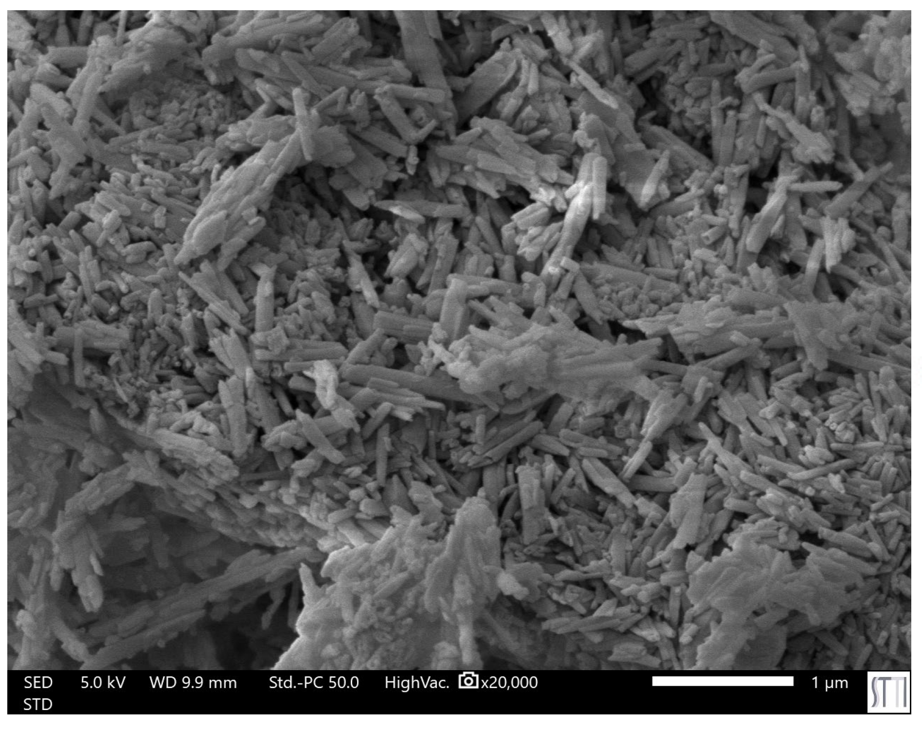
Figure 5.
Flow diagram of the one-shot synthesis protocol of PUs without and with different amounts of HNTs.
Figure 5.
Flow diagram of the one-shot synthesis protocol of PUs without and with different amounts of HNTs.
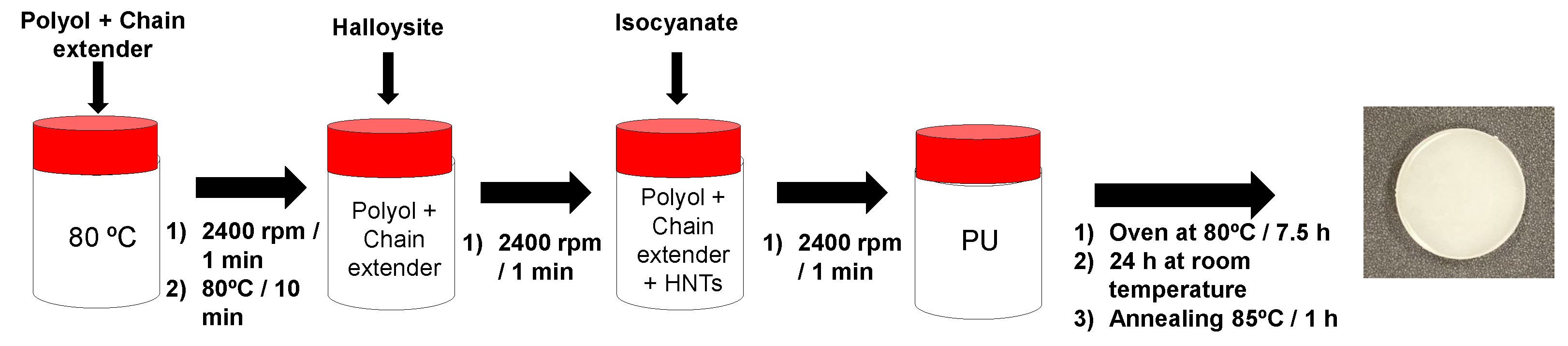
Figure 6.
Scheme of the intrinsic self-healing test performed in PU discs. The process involves (from left to right): initial specimen; partial cut of the disc; re-joining of the cut pieces; manual pressing for 90 seconds; and final healed PU.
Figure 6.
Scheme of the intrinsic self-healing test performed in PU discs. The process involves (from left to right): initial specimen; partial cut of the disc; re-joining of the cut pieces; manual pressing for 90 seconds; and final healed PU.
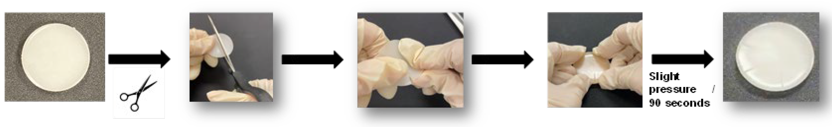
Figure 7.
ATR-IR spectrum of halloysite.
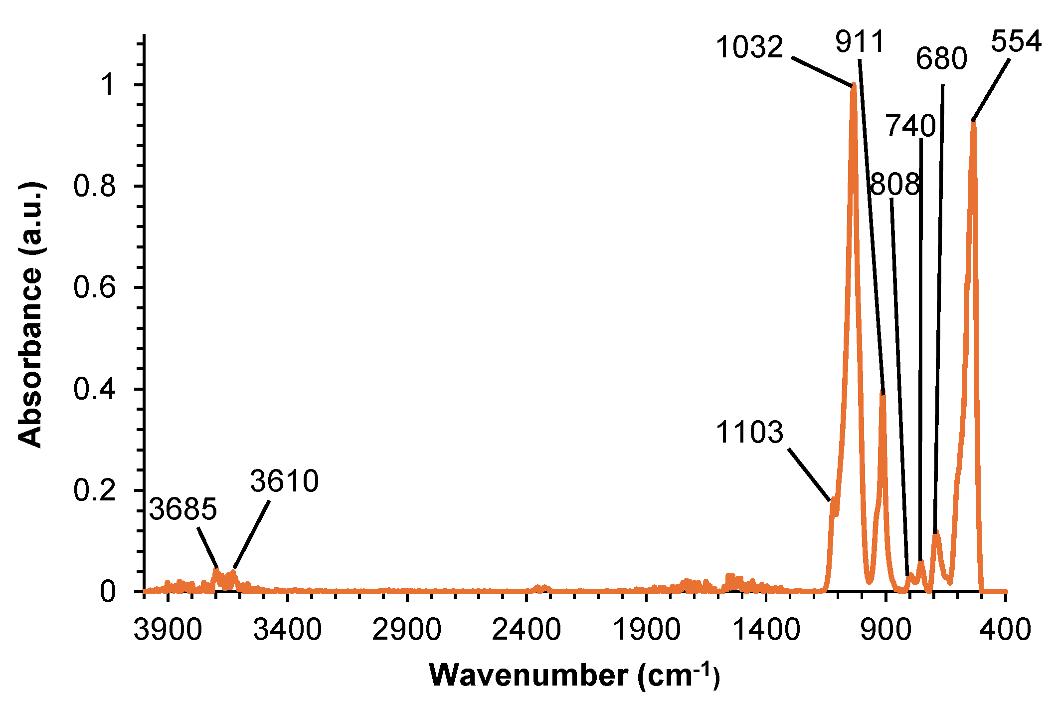
Figure 8.
DSC curves of halloysite corresponding to the first and second heating runs.
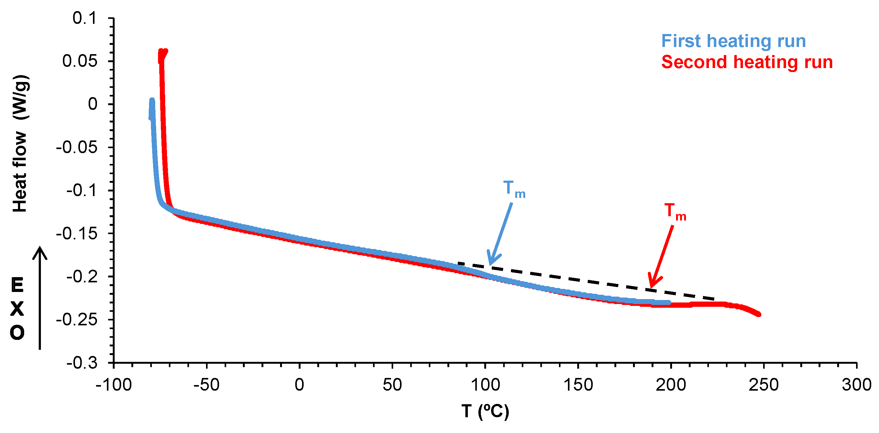
Figure 9.
Self-healing test at room temperature of E0.5-20 and E0.5.
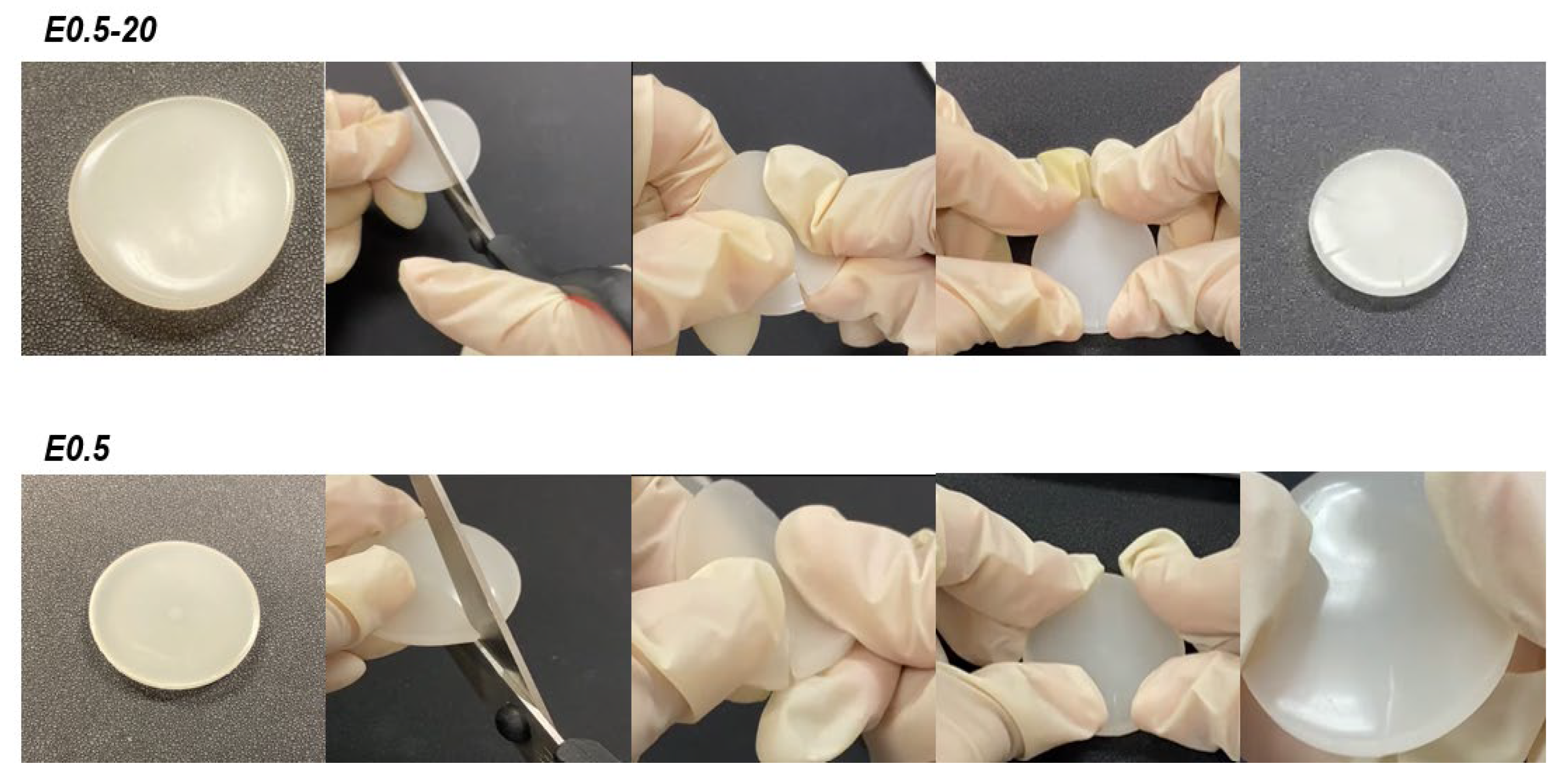
Figure 10.
Stress-strain curves of E0.5-20 and E0.5.
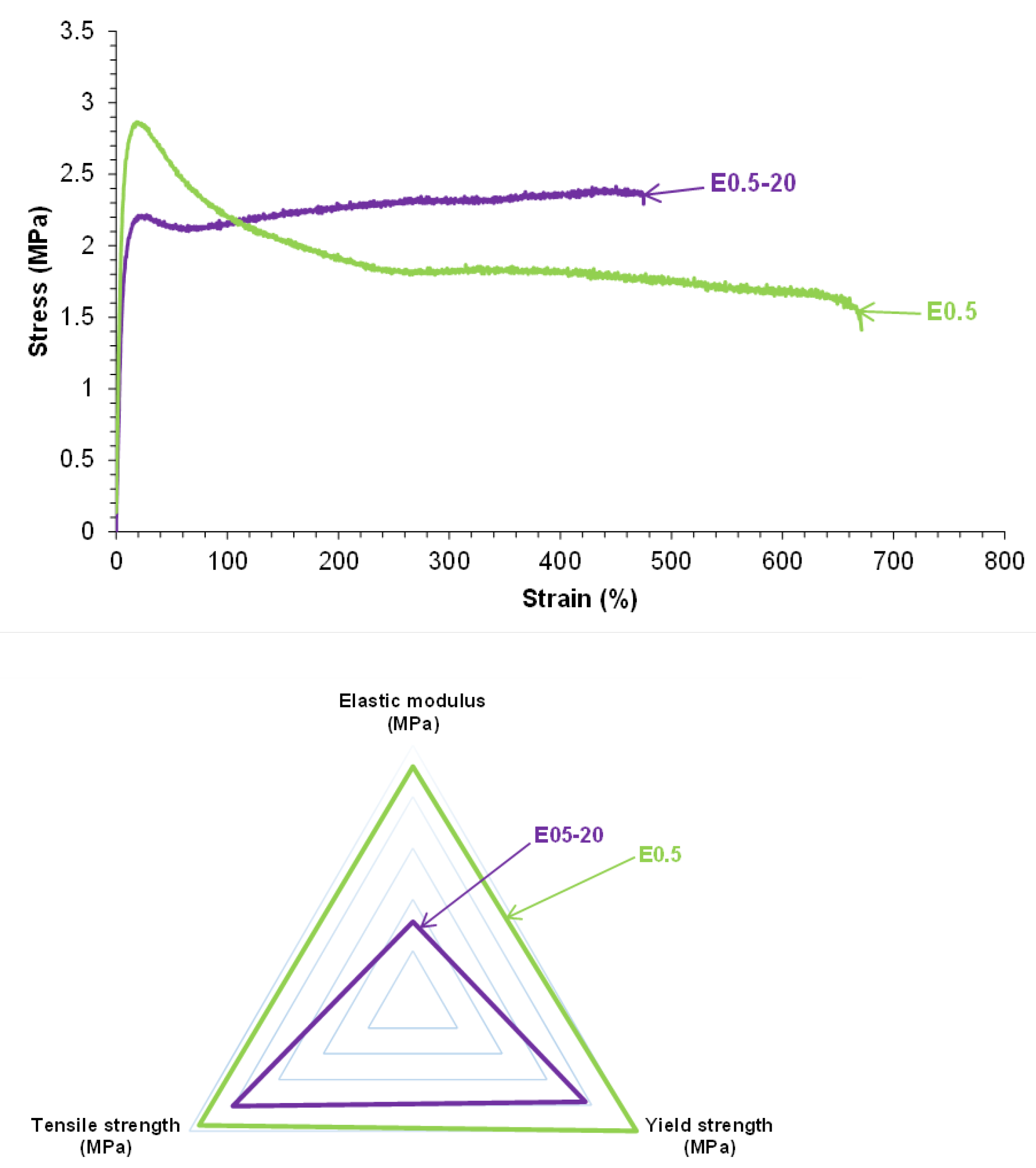
Figure 11.
Curve fitting of the carbonyl stretching region of the ATR-IR spectrum of E0.5.
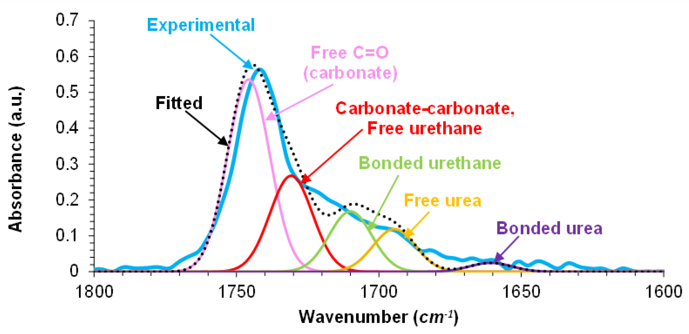
Figure 12.
DSC curves of E0.5-20 and E0.5. First heating run.
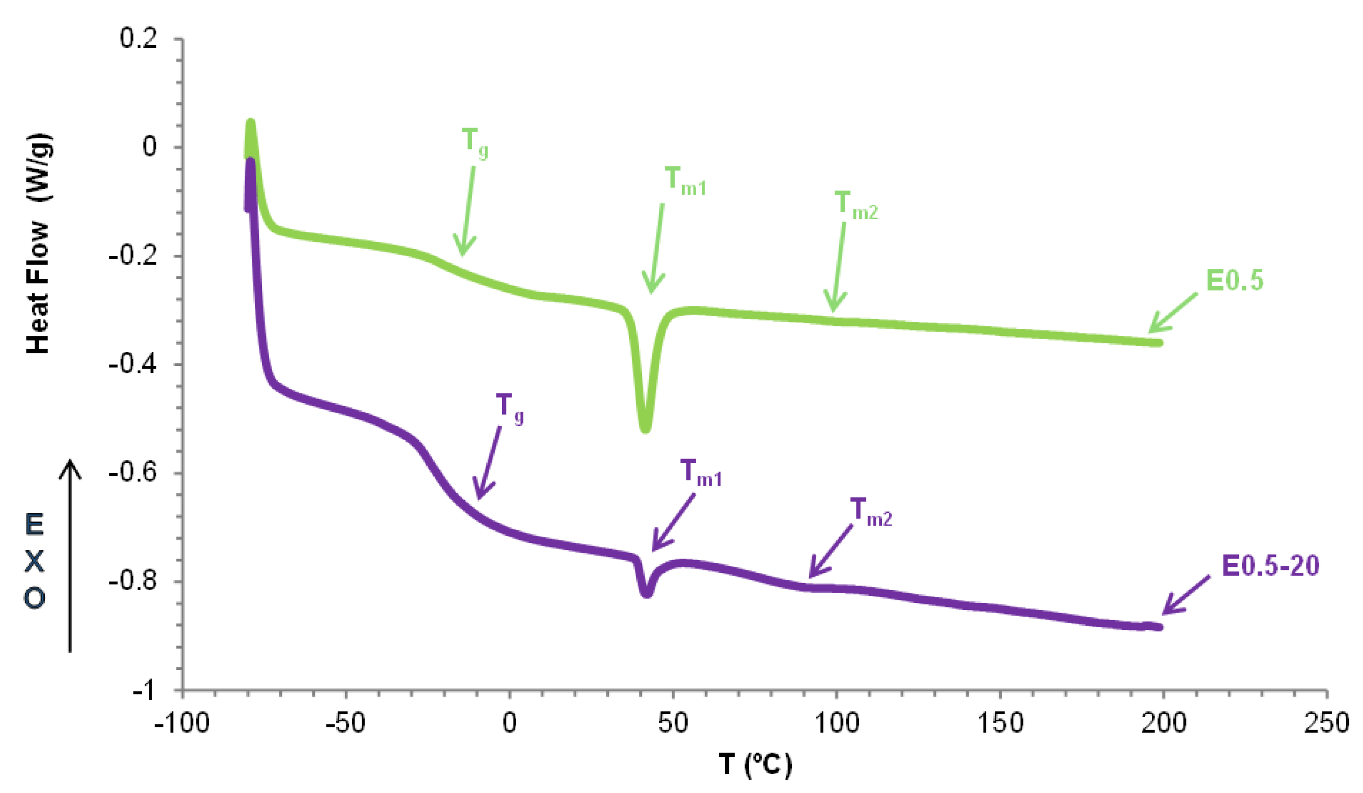
Figure 13.
X-ray diffractograms of E0.5 and E0.5-20.
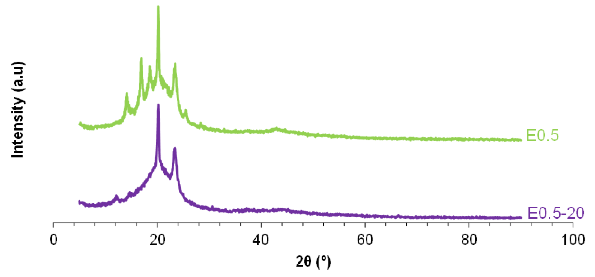
Figure 14.
Variation of the storage modulus as a function of the temperature for E0.5 and E0.5-20.
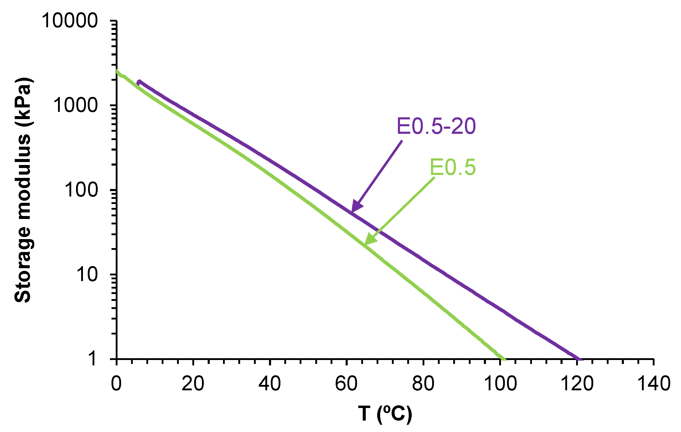
Figure 15.
Visual aspect of unfilled and halloysite filled polyurethanes before (top row) and after (bottom row) intrinsic room temperature self-healing test. Red arrows indicate the location of the initial cut.
Figure 15.
Visual aspect of unfilled and halloysite filled polyurethanes before (top row) and after (bottom row) intrinsic room temperature self-healing test. Red arrows indicate the location of the initial cut.
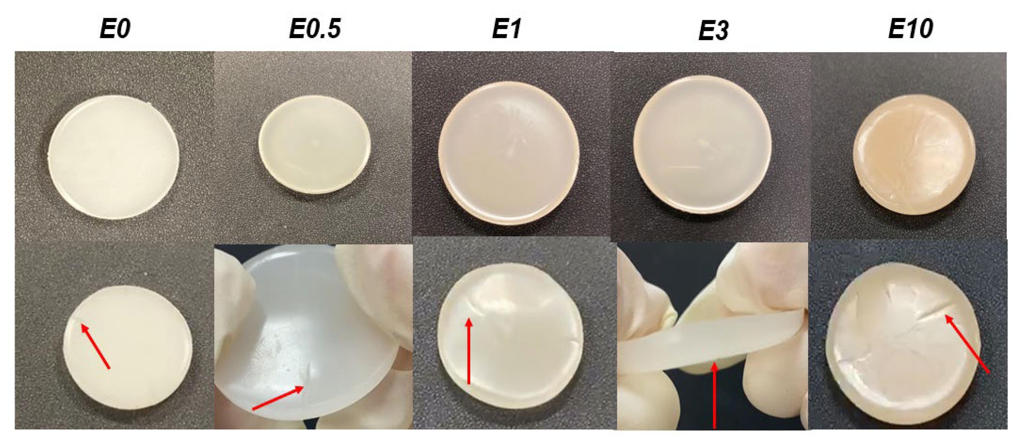
Figure 16.
Stress-strain curves of the polyurethanes without and with different amounts of HNTs.
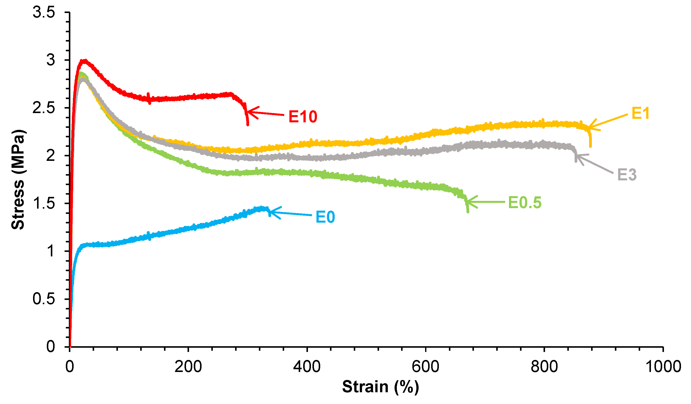
Figure 17.
High-resolution C1s XPS spectrum of E0.5 surface.
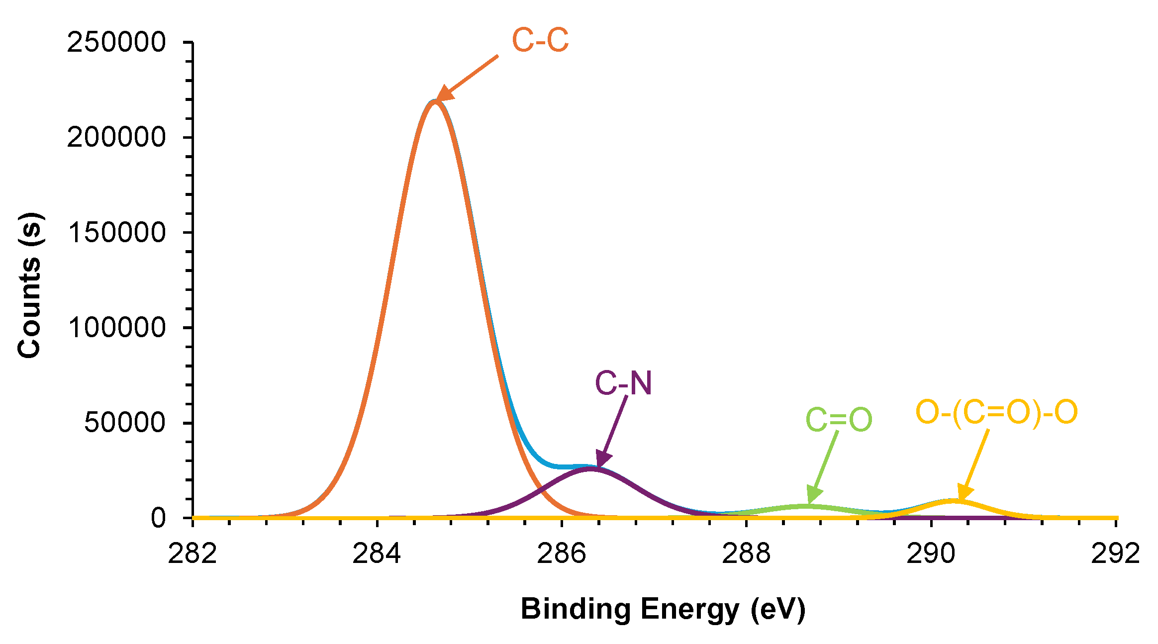
Figure 18.
Derivative of TGA curves of the polyurethanes without and with different amounts of halloysite.
Figure 18.
Derivative of TGA curves of the polyurethanes without and with different amounts of halloysite.
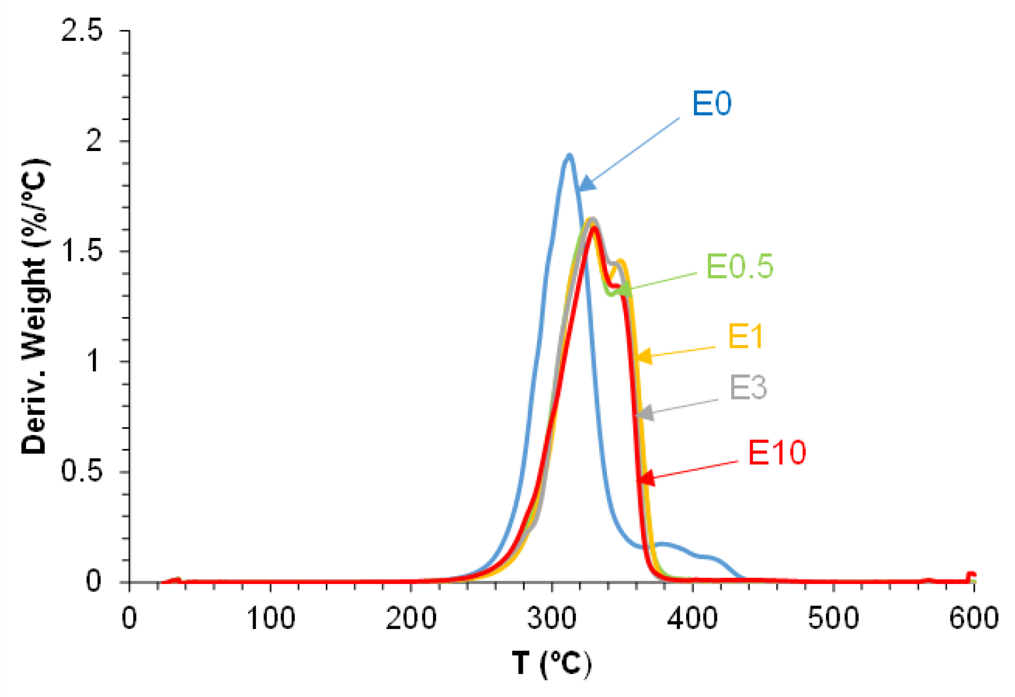
Figure 19.
X-ray diffractograms of polyurethanes without and with different amounts of halloysite.
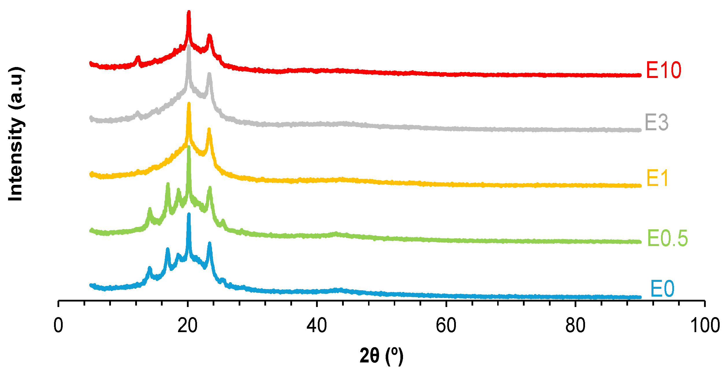
Figure 20.
Variation of the storage modulus as a function of temperature for polyurethanes without and with different amounts of HNTs.
Figure 20.
Variation of the storage modulus as a function of temperature for polyurethanes without and with different amounts of HNTs.
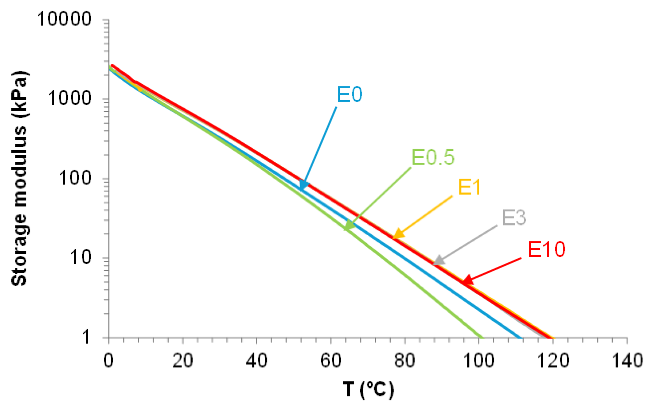
Figure 21.
SEM micrographs of the polyurethanes without and with different amounts of halloysite. X500.
Figure 21.
SEM micrographs of the polyurethanes without and with different amounts of halloysite. X500.
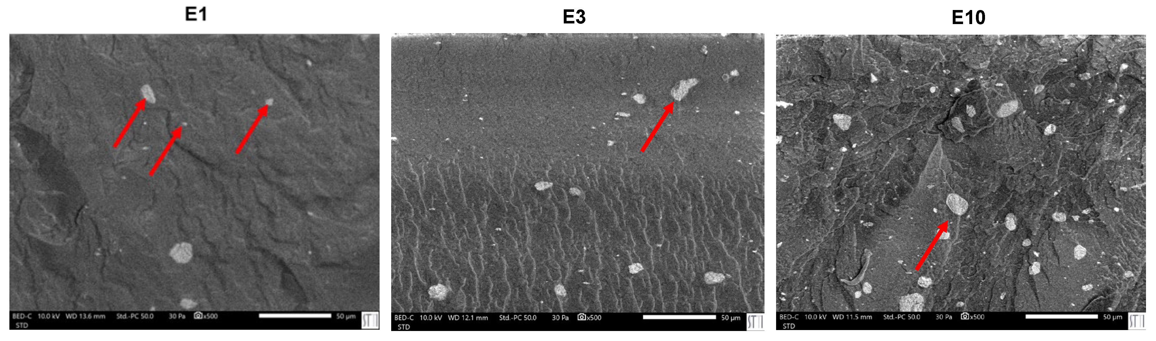
Figure 22.
SEM micrograph of E10 surface. X250.
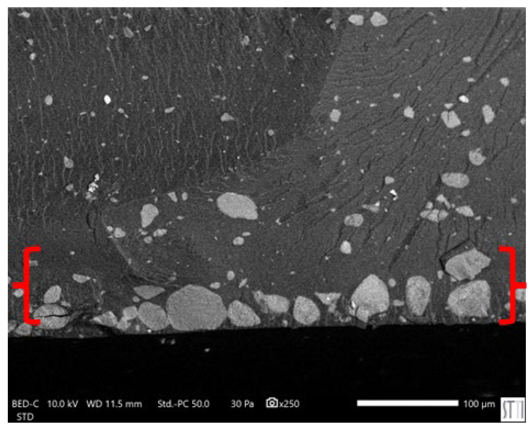
Figure 23.
Schematic representation of the interactions between halloysite and polycarbonate soft segments in polyurethanes with different halloysite content.
Figure 23.
Schematic representation of the interactions between halloysite and polycarbonate soft segments in polyurethanes with different halloysite content.
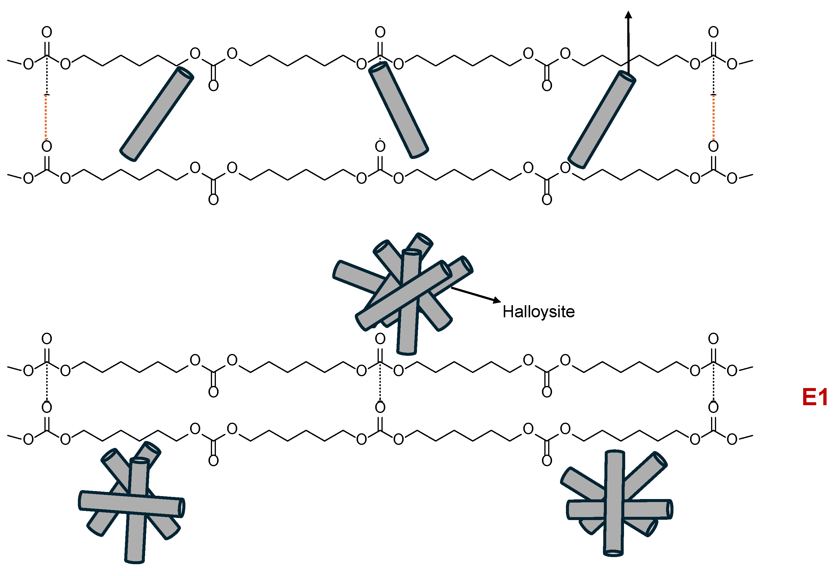

Table 1.
Percentages of different C=O species of E0.5-20 and E0.5. Curve fitting of the carbonyl stretching region of the ATR-IR spectra.
Table 1.
Percentages of different C=O species of E0.5-20 and E0.5. Curve fitting of the carbonyl stretching region of the ATR-IR spectra.
| Wavenumber (cm⁻¹) | Percentage (%) | Assignment | |
| E0.5-20 | E0.5 | ||
| 1745 | 41 | 48 | Free C=O (carbonate) |
| 1730 | 33 | 24 | Carbonate-carbonate, Free urethane |
| 1710 | 14 | 15 | Bonded urethane |
| 1695 | 10 | 11 | Free urea |
| 1660 | 2 | 2 | Bonded urea |
Table 2.
Percentages of C=O species of polyurethanes without and with different amounts of halloysite. Curve fitting of the carbonyl region (1600–1800 cm⁻¹) of the ATR-IR spectra.
Table 2.
Percentages of C=O species of polyurethanes without and with different amounts of halloysite. Curve fitting of the carbonyl region (1600–1800 cm⁻¹) of the ATR-IR spectra.
| Wavenumber (cm⁻¹) | Percentage (%) | Assignment | ||||
| E0 | E0.5 | E1 | E3 | E10 | ||
| 1745 | 49 | 48 | 42 | 39 | 39 | Free C=O (carbonate) |
| 1730 | 25 | 24 | 31 | 33 | 33 | Carbonate-carbonate, Free urethane |
| 1710 | 14 | 15 | 14 | 14 | 15 | Bonded urethane |
| 1695 | 9 | 11 | 11 | 10 | 11 | Free urea |
| 1660 | 3 | 2 | 2 | 4 | 2 | Bonded urea |
Table 3.
Chemical composition on E0, E0.5, and E1 surfaces. Survey XPS.
|
Element |
Percentage (at. %) | ||
| E0 | E0.5 | E1 | |
| C | 84 | 81 | 84 |
| O | 16 | 18.5 | 15 |
| Si | 0.5 | 1 | |
Table 4.
Binding energies and percentages of carbon species on E0, E0.5, and E1 surfaces. High resolution C1s XPS spectra.
Table 4.
Binding energies and percentages of carbon species on E0, E0.5, and E1 surfaces. High resolution C1s XPS spectra.
| Species | Binding energy (eV) | Percentage (at.%) | ||
| E0 | E0.5 | E1 | ||
| C-C | 284.7 | 87 | 85 | 87 |
| C–N | 286.4 | 9 | 10 | 9 |
| C=O | 288.6 | 3 | 2 | 3 |
| O–(C=O)–O | 290.4 | 1 | 3 | 1 |
Table 5.
Binding energies and percentages of oxygen species on E0, E0.5, and E1 surfaces. High resolution XPS spectra.
Table 5.
Binding energies and percentages of oxygen species on E0, E0.5, and E1 surfaces. High resolution XPS spectra.
| Species | Binding energy (eV) | Percentage (at.%) | ||
| E0 | E0.5 | E1 | ||
| C=O | 531.7–531.8 | 75 | 67 | 77 |
| C–O | 533.5–533.7 | 25 | 33 | 23 |
Table 6.
Thermal events obtained from the first heating run of the DSC curves of the polyurethanes without and with different amounts of halloysite.
Table 6.
Thermal events obtained from the first heating run of the DSC curves of the polyurethanes without and with different amounts of halloysite.
| PU | Tg (°C) | ΔCp (J/g·°C) | Tm1 (°C) | ΔHm1 (J/g) | Tm2 (°C) | ΔHm2 (J/g) |
| E0 | -21 | 0.22 | - | - | - | - |
| E0.5 | -20 | 0.20 | 42 | 7.49 | 100 | 0.12 |
| E1 | -22 | 0.32 | 39 | 0.98 | 76 | 0.25 |
| E3 | -21 | 0.37 | - | - | 91 | 0.98 |
| E10 | -22 | 0.22 | 41 | 3.30 | 61 | 0.22 |
| Halloysite | - | - | - | - | 77 | 0.66 |
Table 7.
Temperatures and weight losses of the thermal degradations for polyurethanes without and with different amounts of halloysite.
Table 7.
Temperatures and weight losses of the thermal degradations for polyurethanes without and with different amounts of halloysite.
|
PU |
1st degradation | 2nd degradation | 3rd degradation | 4th degradation | ||||
| T1 (°C) | Weight loss1 (%) | T2 (°C) | Weight loss2 (%) | T3 (°C) | Weight loss3 (%) | T4 (°C) | Weight loss4 (%) | |
| E0 | 297 | 31 | 313 | 60 | - | - | 387 | 6 |
| E0.5 | 283 | 7 | 312 | 28 | 324 | 32 | 347 | 32 |
| E1 | - | - | 314 | 33 | 326 | 34 | 348 | 33 |
| E3 | 281 | 7 | 308 | 18 | 328 | 42 | 346 | 29 |
| E10 | 280 | 7 | 294 | 9 | 330 | 51 | 346 | 27 |
Disclaimer/Publisher’s Note: The statements, opinions and data contained in all publications are solely those of the individual author(s) and contributor(s) and not of MDPI and/or the editor(s). MDPI and/or the editor(s) disclaim responsibility for any injury to people or property resulting from any ideas, methods, instructions or products referred to in the content. |
© 2025 by the authors. Licensee MDPI, Basel, Switzerland. This article is an open access article distributed under the terms and conditions of the Creative Commons Attribution (CC BY) license (http://creativecommons.org/licenses/by/4.0/).
Copyright: This open access article is published under a Creative Commons CC BY 4.0 license, which permit the free download, distribution, and reuse, provided that the author and preprint are cited in any reuse.


