Submitted:
27 August 2025
Posted:
28 August 2025
You are already at the latest version
Abstract
In this study, micro-arc oxidation (MAO) was applied to TA1 titanium alloy using an electrolyte primarily composed of B4O72-, resulting in the successful formation of micro-nano hierarchical rough structure. MAO treatments were conducted in tetraborate-based alkaline solutions containing different cations (Li⁺, Na⁺, K⁺) under constant current conditions. The microstructural characteristics of the oxide layers were systematically investigated using scanning electron microscopy (SEM), X-ray diffraction (XRD), and X-ray photoelectron spectroscopy (XPS). Furthermore, the influence of the cation type on layer thickness, surface roughness, and corrosion resistance was evaluated. The results demonstrate that the oxide layer formed in the Na₂B₄O₇ electrolyte exhibits superior performance in terms of thickness, surface roughness, adhesion strength, and corrosion resistance compared to those obtained using the other two electrolytes.
Keywords:
micro-arc oxidation
; TA1 titanium alloy
; cation effect
; surface morphology and microstructure
; corrosion resistance
1. Introduction
TA1 titanium alloy, as a typical α-type titanium alloy, possesses a stable microstructure and excellent mechanical properties, including high specific strength, fatigue resistance, and a low thermal expansion coefficient. Additionally, it exhibits favorable processability and strong corrosion resistance. Due to these attributes, TA1 has been widely applied in marine engineering and is often referred to as the "marine metal" [1,2]. However, the high concentration of chloride ions (Cl⁻) in marine environments significantly accelerates the corrosion of TA1 titanium alloy. Moreover, the attachment and proliferation of microorganisms can lead to biofouling, which may further induce microbially influenced corrosion [3,4]. To mitigate these challenges, surface modification of TA1 titanium alloy has emerged as a critical technical approach to enhance its corrosion resistance and prolong its service life.
In the field of titanium alloy surface modification, various techniques have been developed, including plasma spraying [5], hydrothermal synthesis [6], laser cladding [7], plasma electrolytic oxidation [8], anodic oxidation [9], and micro-arc oxidation (MAO) [10]. Among these, MAO stands out due to its environmental friendliness and high degree of automation. Under an applied electric field, MAO can rapidly generate a uniform, well-adhered, and hard ceramic oxide coating on the surface of titanium alloys within a short time period [11,12]. This oxide layer exhibits excellent wear resistance, corrosion resistance, and strong interfacial bonding with the substrate [13,14], making it an ideal surface treatment method for enhancing the wear performance of titanium alloys. Consequently, MAO has become a focal point of recent academic research [15].
As a core process parameter in MAO technology, the electrolyte directly determines the properties of the resulting oxide film [16]. Under different electrolyte solution, variations in the film formation mechanism, chemical composition, and microstructural features of the oxide layer can significantly influence its surface performance. Commonly used electrolyte solution for titanium alloy MAO includes silicate, phosphate, and borate-based formulations [17]. The silicate system enhances film thickness through silica deposition but suffers from high surface roughness and relatively weak substrate adhesion [16]. In contrast, the phosphate system yields thinner films with larger surface porosity but demonstrates improved corrosion resistance [18]. Meanwhile, the borate system enables the formation of dense oxide layers with superior wear and corrosion resistance [19].
Given its ability to produce compact and high-performance oxide films, the borate electrolyte solution has become a key focus in the field of titanium alloy surface modification via MAO. Leveraging this advantage, numerous studies have been conducted by researchers worldwide: Liu et al. [20] employed Na2B4O7 electrolyte to fabricate a "cortical-like" TiO2 coating through a one-step methacrylation process; Li et al. [21] constructed a novel micro/nano dual-scale oxide film on pure titanium using a tetraborate-based electrolyte; Zhang et al. [22] applied Na2B4O7·10H2O electrolyte to form an MAO coating on a TA2 titanium alloy weld joint, thereby enhancing the performance of the joint region. In terms of performance optimization, Shi et al. [17] systematically investigated the effect of Na2B4O7 concentration on the wear and corrosion resistance of the oxide film; Wang et al. [23] designed a high B4O72-/PO43- composite electrolyte to elucidate the growth kinetics of oxide films on TC4 titanium alloy surfaces; Zhai et al. [24] further achieved precise microstructural control by optimizing the molar ratio of B4O72- to SiO32-.
In summary, borate-based electrolytes have attracted significant attention due to their capability to produce compact and high-performance MAO films. However, most existing studies focus on the Na2B4O7 system, while systematic investigations into the influence of different cations in tetraborate systems on film formation mechanisms remain limited. Various cations, such as Li⁺ and K⁺, may influence the electrolyte conductivity, ion migration behavior, and reaction kinetics during film formation, thereby altering the microstructure, phase composition, and surface properties of the oxide layer. Furthermore, the application of tetraborate electrolytes for MAO coating preparation on TA1 titanium alloy has not yet been reported. Therefore, this study employs TA1 titanium alloy as the substrate to systematically investigate the effects of tetraborate cation types on the morphological characteristics, phase composition, hardness, and corrosion resistance of MAO films. The objective is to elucidate the cation-mediated regulation mechanisms and provide theoretical support for optimizing borate electrolyte formulations and enhancing the surface protection performance of titanium alloys.
2. Experimental and Methods
2.1. Sample Preparation
The matrix material used in this experiment was commercially available TA1 titanium alloy, with dimensions of 10 mm × 20 mm × 2 mm. Its chemical composition is presented in Table 1-1. The substrate was pre-treated as follows: first ground sequentially with SiC sandpapers of grit sizes 200#, 600#, 1000#, and 1500#, followed by polishing with diamond grinding pastes of 2.5 W, 1.5 W, and 0.5 W. Subsequently, the samples were ultrasonically cleaned in acetone, ethanol, and deionized water for 15 minutes each, and finally dried using a hair dryer. Sodium tetraborate (Na2B4O7) was purchased from Chengdu Macklin Biotechnology Co., Ltd., while heptadecafluorodecyl triethoxysilane (PFDTES) was supplied by Shanghai Macklin Biochemical Technology Co., Ltd.
2.2. Preparation of MAO Film on TA1 Titanium Alloy Surface
In this study, a JCL-WH20 multi-functional MAO apparatus (manufactured in Chengdu, China) was employed to fabricate the TiO2 film. The detailed procedure is as follows: First, a 1 L solution of 0.1 mol/L Na2B4O7 was prepared at room temperature and continuously stirred for 12 hours to ensure complete dissolution of the electrolyte ions. Subsequently, a 15 cm long aluminum rod with a diameter of 2 mm was used to clamp the sample as the anode, while a stainless steel plate served as the cathode. The MAO process was conducted in constant current mode. During the treatment, the stirring speed was precisely maintained between 30 and 35 r/min to ensure uniform electrolyte distribution. Simultaneously, the cooling system was activated to keep the electrolyte temperature at 30 ± 5 °C, preventing overheating caused by excessive thermal accumulation. Upon completion of the reaction, the obtained samples were immersed in boiling deionized water at 100 °C for 5 minutes to perform a sealing treatment, and then dried using a hair dryer.
2.3. Characterization of the MAO Coating on TA1 Titanium Alloy Surface
In this study, the surface morphology of the MAO coating before and after modification was examined using a Scanning Electron Microscope (SEM, ZEISS EVO MA15, Carl Zeiss Microscopy GmbH, Jena, Germany). The elemental distribution and relative content on the coating surface were analyzed by Energy Dispersive Spectroscopy (EDS, OXFORD 20, Carl Zeiss Microscopy GmbH, Jena, Germany).
The phase composition of the coating was determined through X-ray diffraction (XRD) analysis using a DX-2700B X-ray diffractometer (Dandong Haoyuan Instrument Co., Ltd., Dandong, China). The experimental parameters were as follows: a Cu Kα radiation source was employed, with an accelerating voltage and current of 40 kV and 40 mA, respectively. The scanning step size was set to 0.0167°, the dwell time to 12 s, and the scanning speed was approximately 0.1°/min.
The chemical composition and oxidation states of elements on the coating surface were investigated using a Nexsa X-ray photoelectron spectrometer (Thermo Scientific), with an energy scanning range of 0–1350 eV. The static contact angle of the coating was measured using an OCA 25 automatic contact angle meter (Thermo Scientific). During the measurement, three distinct locations on each sample were selected, and the average value was calculated. The water droplet volume was fixed at 5 μL, with a dispensing rate of 1 μL/s.
The corrosion resistance of the MAO ceramic coating was evaluated using a Reference 3000 electrochemical workstation (Gamry, Philadelphia, PA, USA) in a 3.5 wt.% NaCl solution at 25 °C. A conventional three-electrode configuration was employed, with the sample as the working electrode, a platinum electrode as the counter electrode, and a saturated calomel electrode as the reference electrode. Electrochemical Impedance Spectroscopy (EIS) measurements were conducted over a frequency range of 100 kHz to 0.01 Hz with an AC amplitude of ±10 mV and a test area of 1 cm².
3. Results
3.1. The Thickness, Surface Roughness, and Adhesion Properties of the Film Layer
Figure 1(a) presents the oxidation voltage–time curves obtained during the preparation of MAO films using Li2B4O7, Na2B4O7, and K2B4O7 electrolytes. As shown in the figure, during the initial oxidation stage, the voltage rise rates decrease progressively from Li2B4O7 to Na2B4O7 and then to K2B4O7. Concurrently, the duration of the spark discharge stage shortens in the order Li2B4O7 > Na2B4O7 > K2B4O7, the onset of the stable oxidation stage occurs earlier, and the duration of the stable oxidation stage increases sequentially. At the end of the MAO process, the Na2B4O7 electrolyte exhibits the highest terminal voltage of 399 V, whereas the Li2B4O7 electrolyte shows the lowest terminal voltage of only 379 V.
It is well established that the ionic radii follow the order Li+ < Na+ < K+[25]. With the increase in ionic radius, ionic mobility enhances (K⁺ > Na⁺ > Li⁺), which promotes the hydrolysis of borate species and leads to the generation of more hydroxyl (-OH) groups. This results in an increase in solution pH and a corresponding rise in electrical conductivity. Consequently, during the initial oxidation stage, the voltage in the K2B4O7 electrolyte solution rises most rapidly and reaches a stable value earlier than in other systems [26]. However, during the stable oxidation stage, the Na2B4O7 electrolyte exhibits a higher voltage and longer duration due to more intensive hydrolysis (generating more -OH groups) compared to K2B4O7, leading to the highest terminal voltage (399 V) among the three systems.
As shown in Figure 1(b), the thicknesses of the TM(Li)C, TM(Na)C, and TM(K)C films are 7.6 μm, 13.4 μm, and 12.4 μm, respectively, with TM(Na)C exhibiting the maximum thickness. With respect to surface roughness, the corresponding values are 0.316 μm, 1.690 μm, and 1.683 μm, indicating that TM(Na)C has a slightly higher surface roughness than TM(K)C. In terms of adhesion strength, the measured values are 8 N, 14 N, and 9 N, respectively, demonstrating that TM(Na)C possesses the strongest adhesion.
When the MAO process reached the 20th minute, the voltage of the Na2B4O7 electrolyte began to surpass that of the K2B4O7 electrolyte, exhibiting a gradual upward trend. The higher voltage provided additional energy, which accelerated the formation and ejection of oxides around the discharge channels, thereby enhancing the growth rate of the coating.
3.2. Surface Morphology and Elemental Composition
Figure 2 presents the SEM images and elemental distributions of the films fabricated on a TA1 substrate using Li2B4O7, Na2B4O7, and K2B4O7 electrolytes, respectively. Prior to MAO treatment, the TA1 surface exhibited a smooth and flat morphology, predominantly composed of Ti with trace amounts of C. Upon applying the micro-arc oxidation process with the three tetraborate-based electrolytes, all resulting film surfaces displayed brain-like sulcus structures to varying extents, along with uniformly distributed groove-like features approximately 5–15 μm in width. This surface morphology resembles that obtained through physical or chemical etching. The film surfaces were primarily composed of Ti and O elements, with minor B content.
The absence of layered accumulation of oxides ejected from discharge channels on the film surface can be attributed to the relatively weak adsorption capacity of the MAO film for B4O72-, as well as the dissolution effect of B2O3(generated via B4O72- hydrolysis)on the ejected oxides. Among the films prepared using different electrolytes, the TM(Li)C film exhibited the least distinct groove distribution, the TM(K)C film showed a more pronounced groove structure, while the TM(Na)C film displayed the most evident groove morphology.
Furthermore, after MAO treatment, all electrolytes exhibited varying degrees of blue coloration. The intensity of the blue color was positively correlated with the amount of oxide dissolved during the discharge process. Visual observation revealed that the color deepened in the order TM(Li)C < TM(K)C < TM(Na)C, where the intensity of the blue color was positively correlated with the amount of oxide dissolved during the discharge process. This sequence further indicates that the oxide dissolution behavior increases in the order TM(Li)C < TM(K)C < TM(Na)C among the electrolyte solutions.
From visual inspection, the groove depths of different film layers exhibit distinct variations, following the order: TM(Na)C > TM(K)C > TM(Li)C. As illustrated in Figure 3, static contact angle measurements of the sample surfaces further validate this trend. The TA1 substrate displays a static contact angle of 61.5°, indicating a clear hydrophilic nature. After micro-arc oxidation treatment using borate electrolytes, the surface hydrophilicity is further enhanced. Specifically, the TM(Na)C film exhibits the lowest contact angle of 17.3°, significantly lower than those of TM(Li)C (26.4°) and TM(K)C (24.7°), which aligns well with the observed differences in groove depth.
The formation of oxide layers on the TA1 surface is accompanied by an increase in surface roughness. According to the Wenzel model [27], increased surface roughness enhances the spreading ability of liquids on the surface. In other words, a rougher surface exhibits a stronger adsorption capacity for liquids, facilitating greater liquid spreading. Consequently, within the tetraborate-based electrolyte solution, the MAO film prepared using Na2B4O7 electrolyte demonstrates the highest hydrophilicity, which is closely associated with its maximum surface roughness.
Table 2 presents the EDS elemental composition data of the TA1 substrate and the films prepared using Li2B4O7, Na2B4O7, and K2B4O7 electrolytes. As shown in the table, the TA1 substrate is predominantly composed of Ti, with only trace amounts of C. The surfaces of the TM(Li)C, TM(Na)C, and TM(K)C films are all composed of Ti, O, and B elements. The atomic ratio of Ti to O is approximately 1:2 across all samples, providing strong evidence that the surface oxide is present in the form of TiO2. Although the mass and atomic percentages of B in the films are very low, variations in B content can reflect differences in the duration of the B2O3 dissolution process or the approximate quantity of dissolved deposits [28]. Specifically, the order of B content (both by mass and atomic percentage) is TM(K)C > TM(Li)C > TM(Na)C.
In conjunction with the previously observed groove depth differences, the following analysis can be made: The TM(Na)C film exhibits the deepest and most extensive grooves, indicating a greater degree of titanium-containing oxide dissolution and, consequently, minimal residual boron-containing oxides. In contrast, the grooves on the TM(K)C and TM(Li)C films are more localized. However, despite the TM(K)C film displaying relatively deeper grooves, it retains a higher amount of residual boron-containing oxides. This phenomenon may be attributed to the more pronounced groove morphology in TM(K)C, which increases the apparent frequency of oxide detection within the same scanning area.
As shown in Figure 4, when the anions in the electrolyte are all B4O72- and the cations are Li⁺, Na⁺, and K⁺, respectively, the resulting MAO coatings are composed of rutile TiO2 (#21-1276 Rutile), anatase TiO2 (#21-1272 Anatase), and α-Ti (#44-1294 Ti). The phase composition ratios are as follows: in the TM(Li)C coating, the ratio of rutile TiO2: anatase TiO2: α-Ti is 8.4%: 6.9%: 84.7%; in TM(Na)C, it is 13.5%: 3.8%: 82.6%; and in TM(K)C, it is 13.3%: 3.3%: 83.4%. Among these, the TM(Na)C coating exhibits the highest total TiO2 content (17.3%), with rutile TiO2 being the dominant phase at 13.5%.
TiO2 surfaces tend to generate negatively charged -OH groups in humid environments. Rutile TiO2 (R-TiO2) is the most thermodynamically stable crystalline form of TiO2 [29] and is considered a high-temperature stable phase. Its (110) crystal plane possesses the lowest surface free energy among all TiO2 planes and contains a higher density of -OH groups [21], which enhances the bridging capability of surface oxygen species. When water droplets contact surfaces rich in rutile TiO2, they are more likely to dissociate, supporting the observation that the TM(Na)C coating exhibits a lower static contact angle compared to the other two coatings. Additionally, the effect of surface roughness on wettability should not be overlooked.
In summary, variations in hydrolysis capacity and diffusion behavior among cations in the tetra-borate-based MAO electrolyte solution primarily influence the morphological features of the coatings, but do not alter the types of crystalline phases present. However, these differences do lead to significant variations in the relative phase content ratios.
The absence of detectable boron-containing phases in the XRD patterns may be attributed to the low surface concentration of B in the film layers and the formation of predominantly amorphous structures during cooling from the molten state [30]. To further investigate the chemical states and bonding configurations of O, Ti, and B elements in the three film layers, XPS analysis was performed.
As shown in the full-scan XPS spectra in Figure 5(a), O, Ti, and B elements were all detected on the surfaces of the three film layers. The specific relative atomic concentrations are as follows: in the TM(Li)C film layer, O, Ti, and B account for 56.7%, 41.7%, and 1.66%, respectively; in TM(Na)C, 56.6%, 42.8%, and 0.6%; and in TM(K)C, 59.5%, 40.3%, and 0.02%. These findings are consistent with the elemental composition previously obtained by EDS analysis.
The high-resolution B 1s spectrum in Figure 5(b) reveals that the binding energy peaks for B in all three coatings are centered at 191.8 eV. In Figure 5(c), the Ti 2p spectrum can be deconvoluted into two peaks corresponding to Ti2p3/2 and Ti2p1/2 at 458.6 eV and 464.3 eV, respectively, with a spin-orbit splitting energy of 4.3 eV, which aligns well with previously reported data [31]. This confirms that Ti exists predominantly in the +4 oxidation state on the film surfaces.
The O 1s spectrum in Figure 5(d) can be fitted with two distinct peaks: one at 529.9 eV, attributed to Ti–O bonds, and another at 531.7 eV [30], corresponding to B–O bonds. Taken together, these results confirm that the outer surface of the film layers is primarily composed of TiO2 with a minor presence of B₂O₃.
3.3. Corrosion Resistance
The corrosion potential (Ecorr) in a film layer's polarization curve reflects the thermodynamic tendency of the corrosion process; a more positive Ecorr indicates a lower tendency for corrosion to occur. In contrast, the corrosion current density (icorr) represents the kinetic aspect of the corrosion process; a lower icorr indicates a stronger corrosion resistance of the film layer. Figure 6 presents the potentiodynamic polarization curves of the TA1 substrate and the MAO coatings prepared using different electrolytes. As shown, compared with the TA1 substrate, the Ecorr values of the TM(Li)C, TM(K)C, and TM(Na)C coatings become progressively more positive, while the icorr values decrease sequentially.
According to the fitting results of the polarization curves listed in Table 3, the Ecorr and icorr of the TA1 substrate are -468.38 mV and 5.8027×10⁻⁶ A·cm-2, respectively, which are in good agreement with previously reported data [33]. For the TM(Li)C, TM(K)C, and TM(Na)C coatings, the Ecorr increases and the icorr decreases in the same order. Notably, the coating fabricated using the Na2B4O7 electrolyte exhibits the highest Ecorr of -254.13 mV and the lowest icorr of 8.0435×10⁻⁸ A·cm-2, corresponding to a corrosion rate (MPY) of only 0.064. Compared to the TA1 substrate, this represents an increase in Ecorr by approximately 214.25 mV and a reduction in icorr by nearly two orders of magnitude. These results demonstrate that the micro-nanostructured TiO2 coating formed by MAO significantly enhances the corrosion resistance of the TA1 substrate.
To further elucidate the electrochemical corrosion behavior of the TA1 substrate and the MAO coatings, electrochemical impedance spectroscopy (EIS) measurements were conducted [34]. As shown in the Nyquist plot (Figure 7a), the capacitive arc radii of the TM(Li)C, TM(K)C, and TM(Na)C coatings increase progressively compared to that of the TA1 substrate, indicating a gradual enhancement in their resistance to corrosive ion penetration.
The impedance modulus plots in Figure 7(b) reveal that, in the high-frequency range of 104 to 105 Hz, the slope of the curve is nearly zero, showing an approximately horizontal trend. This suggests that the solution resistance remained relatively stable throughout the measurement. In the low-frequency region (Figure 7c), the phase angle values increase sequentially, confirming a progressive rise in low-frequency impedance, which aligns with the variation trend of the impedance modulus. Notably, the phase angle curve of the bare TA1 substrate exhibits only a single peak, corresponding to one time constant, whereas the MAO coatings display two distinct peaks, indicating the presence of two-time constants associated with different electrochemical processes.
Figure 8 presents the equivalent electrical circuits used to fit the EIS data for the TA1 substrate and the three types of micro-arc oxidation coatings in a 3.5 wt.% NaCl solution. The TA1 substrate is best fitted using the R(QR) model, while the MAO coatings are described by the more complex R(QR)(QR) model. The fitting parameters are defined as follows: Rs denotes the solution resistance between the auxiliary and working electrodes [35]; Qdl represents the constant phase element associated with the double-layer capacitance at the electrolyte–substrate interface; Rct is the charge transfer resistance at the interface; Rc refers to the coating resistance; and Qc corresponds to the constant phase element representing the dielectric behavior of the micro-arc oxidation coating. Due to the surface roughness and inhomogeneity of the coatings, constant phase elements (Q) were used instead of ideal capacitors (C) to achieve more accurate fitting results [36].
As summarized in Table 4, the Rct values of the TM(Li)C, TM(K)C, and TM(Na)C coatings increase in that order and are significantly higher than that of the TA1 substrate. This indicates that the MAO coatings effectively enhance the charge transfer resistance and provide superior protection against corrosion. Specifically, the Rct value of the TA1 substrate is 2.115×10⁴ Ω·cm2, whereas that of the TM(Na)C coating reaches 5.5×10⁵ Ω·cm², representing an increase of approximately 25 times. The EIS results are in good agreement with the trends observed in the potentiodynamic polarization curves, further confirming that under the tetraborate-based electrolyte system, the micro-nanostructured TiO2 coatings formed under different cation conditions exhibit improved corrosion resistance with increasing coating thickness and rutile-phase TiO2 content [37].
4. Conclusions
In this study, MAO was performed on TA1 substrates using Li2B4O7, Na2B4O7, and K2B4O7 electrolytes, and the resulting coatings were systematically evaluated in terms of their structural and electrochemical properties. The results demonstrated that the coating fabricated using the Na2B4O7 electrolyte exhibited superior performance in thickness, surface roughness, adhesion strength, and corrosion resistance compared to those obtained with the other two electrolytes. The surface morphology of the coatings displayed a brain-groove-like structure and was primarily composed of TiO2 along with a minor amount of B2O3. Notably, the TM(Na)C coating showed the highest TiO2 content, with rutile TiO2 accounting for 13.5%. The Ti element existed predominantly in the +4 oxidation state (Ti⁴⁺), while oxygen was mainly present in the forms of B–O and Ti–O bonds. Electrochemical corrosion tests revealed that the TM(Na)C coating achieved the highest Ecorr, the lowest icorr, and the highest Rct, significantly outperforming the bare TA1 substrate. These improvements were primarily attributed to the higher voltage and extended stable oxidation period provided by the Na2B4O7 electrolyte during the MAO process, which facilitated coating growth and the formation of the protective TiO2 phase, thereby enhancing the overall corrosion resistance.
Author Contributions
Investigation, X.P. and M.H.; resources, quality control and reply to review comments, X.Z. and D.X.; data curation, H.W.; writing—original draft preparation and revision, L.Z. ; team coordination, writing—review and editing, submission decision, S.W. All authors have read and agreed to the published version of the manuscript.
Funding
This research received no external funding.
Institutional Review Board Statement
Not applicable.
Informed Consent Statement
Not applicable.
Data Availability Statement
The original contributions presented in this study are included in the article. Further inquiries can be directed to the corresponding authors.
Conflicts of Interest
Author Dinghan Xiang were employed by the Guangxi Key Laboratory of Information Materials, Guilin University of Electronic Technology. Author Meng Huang was employed by the company China Petroleum Southwest Oil and Gas Field Company Chongqing Gas Mine. The remaining authors declare that the research was conducted in the absence of any commercial or financial relationships that could be construed as a potential conflict of interest.
References
- Zhang, L.; Wu, K.; Zhou, G.; Lan, Z. Design, Preparation, and Experiment of the Titanium Alloy Thin Film Pressure Sensor for Ocean Depth Measurements. IEEE Sensors Journal 2024, 24, 14042–14049. [Google Scholar] [CrossRef]
- Lin, J.; Dan, Z.; Lu, J.; Ding, Y.; Wang, Y.; Chang, H.; Zhou, L. Research Status and Prospect on Marine Corrosion of Titanium Alloys in Deep Ocean Environments. Rare Metal Materials and Engineering 2020, 49, 1090–1099. [Google Scholar]
- Butt, H.J.; Vollmer, D.; Papadopoulos, P. Super liquid-repellent layers: The smaller the better. Advances in Colloid and Interface Science, 2015, 222, 104–109. [Google Scholar] [CrossRef]
- Manoj, T.P.; Rasitha, T.P.; Vanithakumari, S.C.; Anandkumar, B.; George, R.P.; Philip, J. A simple, rapid and single step method for fabricating superhydrophobic titanium surfaces with improved water bouncing and self-cleaning properties. Applied Surface Science 2020, 512, 145636. [Google Scholar] [CrossRef]
- Hussain, S.; Shah, Z.A.; Sabiruddin, K.; Keshri, A.K. Characterization and tribological behaviour of Indian clam seashell-derived hydroxyapatite coating applied on titanium alloy by plasma spray technique. Journal of the mechanical behavior of biomedical materials 2023, 137, 105550. [Google Scholar] [CrossRef]
- Liu, Y.; Yang, L.; Yang, X.; Zhang, T.; Sun, R. Optimization of microstructure and properties of composite coatings by laser cladding on titanium alloy. Ceramics International 2021, 47, 2230–2243. [Google Scholar] [CrossRef]
- Zhang, K.; Li, B.; Liu, W.; Liu, W.; Wang, W.; Wang, H.; Bian, H. Influences of friction stir processing on the microstructure and properties of TC4 titanium alloy by laser metal deposition. Journal of Alloys and Compounds 2024, 1008, 176769. [Google Scholar] [CrossRef]
- Grigoriev, S.; Peretyagin, N.; Apelfeld, A.; Smirnov, A.; Morozov, A.; Torskaya, E.; Volosova, M.; Yanushevich, O.; Yarygin, N.; Krikheli, N.; Peretyagin, P. Investigation of Tribological Characteristics of PEO Coatings Formed on Ti6Al4V Titanium Alloy in Electrolytes with Graphene Oxide Additives. Materials 2023, 16, 3928. [Google Scholar] [CrossRef]
- Jáquez-Muñoz, J.M.; Gaona-Tiburcio, C.; Mendez-Ramirez, C.T.; Carrera-Ramirez, M.G.; Baltazar-Zamora, M.A.; Santiago-Hurtado, G.; Lara-Banda, M.; Estupiñan-Lopez, F.; Nieves-Mendoza, D.; Almeraya-Calderon, F. Corrosion of Anodized Titanium Alloys. Coatings 2024, 14, 809. [Google Scholar] [CrossRef]
- [Lan, X.; Wang, P.; Gong, Z.; Luo, X.; Zheng, Y.; Deng, B. ; Effect of Phytic Acid Modification on Characteristics of MAO Coating on TC4 Titanium Alloy. Rare Metal Materials and Engineering 2024, 53, 954–962. [Google Scholar]
- Yerokhin, A.L.; Nie, X.; Leyland, A.; Matthews, A.; Dowey, S.J. Plasma electrolysis for surface engineering. Surface and Coatings Technology 1999, 122, 73–93. [Google Scholar] [CrossRef]
- Fazel, M.; Salimijazi, H.R.; Golozar, M.A.; Garsivaz jazi, M.R. A Comparison of Corrosion, Tribocorrosion and Electrochemical Impedance Properties of Pure Ti and Ti6Al4V Alloy Treated by Micro-Arc Oxidation Process. Applied Surface Science 2015, 324, 751–756. [Google Scholar] [CrossRef]
- Yao, W.; Wu, L.; Wang, J.; Jiang, B.; Zhang, D.; Serdechnova, M.; Shulha, T.; Blawert, C.; Zheludkevich, M.L.; Pan, F. Micro-Arc Oxidation of Magnesium Alloys: A Review. Journal of Materials Science &Technology 2022, 118, 158–180. [Google Scholar]
- Huang, Y.; Sun, X.; Song, J.; Chen, J.; Gao, J.; Xiao, K. Study on Corrosion Protection Behavior of Magnesium Alloy/Micro-Arc Oxidation Coating in Neutral Salt Spray Environment. International Journal of Electrochemical Science 2023, 18, 100179. [Google Scholar] [CrossRef]
- Li, G.; Ma, F.; Liu, P.; Qi, S.; Li, W.; Zhang, K.; Chen, X. Review of micro-arc oxidation of titanium alloys: Mechanism, properties and applications. Journal of Alloys and Compounds 2023, 948, 169773. [Google Scholar] [CrossRef]
- Li, Q.; Yang, W.; Liu, C.; Wang, D.; Liang, J. Correlations between the growth mechanism and properties of micro-arc oxidation coatings on titanium alloy: Effects of electrolytes. Surface and coatings technology 2017, 316, 162–170. [Google Scholar] [CrossRef]
- Shi, W.; Hai, J.; Shan, C.; Zhang, X.; Yang, Q.; Ma, X. Effect of Na2B4O7 on Wear and Corrosion Resistance of Micro-arc Oxidation Coating on Titanium Alloy. Surface Technology 2024, 53, 88–98. [Google Scholar]
- Shokouhfar, M.; Dehghanian, C.; Montazeri, M.; Baradaran, A. Preparation of Ceramic Coating on Ti Substrate by Plasma Electrolytic Oxidation in Different Electrolytes and Evaluation of Its Corrosion Resistance: Part II. Applied Surface Science 2012, 258, 2416–2423. [Google Scholar] [CrossRef]
- Pavarini, M.; Moscatelli, M.; Candiani, G.; Tarsini, P.; Cochis, A.; Rimondini, L.; Najmi, Z.; Rocchetti, V.; De Giglio, E.; Cometa, S.; De Nardo, L.; Chiesa, R. Influence of Frequency and Duty Cycle on the Properties of Antibacterial Borate-Based PEO Coatings on Titanium for Bone-Contact Applications. Applied Surface Science 2021, 567, 150811. [Google Scholar] [CrossRef]
- Liu, Z.; Wang, W.; Liu, H.; Wang, T.; Qi, M. Formation and characterization of titania coatings with cortex-like slots formed on Ti by micro-arc oxidation treatment. Applied Surface Science 2013, 266, 250–255. [Google Scholar] [CrossRef]
- Li, Y.; Wang, W.; Liu, H.; Lei, J.; Zhang, J.; Zhou, H.; Qi, M. Formation and in vitro/in vivo performance of “cortex-like” micro/nano-structured TiO2 coatings on titanium by micro-arc oxidation. Materials Science and Engineering: C 2018, 87, 90–103. [Google Scholar] [CrossRef]
- Zhang, D.; Zhang, X.; Wei, E.; Dou, X.; He, Z. Construction of superhydrophobic film on the titanium alloy welded joint and its corrosion resistance study. Anti-Corrosion Methods and Materials 2023, 70, 328–340. [Google Scholar] [CrossRef]
- Wang, X.; Zhang, F. Influence of anions in phosphate and tetraborate electrolytes on growth kinetics of microarc oxidation coatings on Ti6Al4V alloy. Transactions of Nonferrous Metals Society of China 2022, 32, 2243–2252. [Google Scholar] [CrossRef]
- Zhai, D.; Qiu, T.; Shen, J.; Feng, K. Mechanism of tetraborate and silicate ions on the growth kinetics of microarc oxidation coating on a Ti6Al4V alloy. RSC Advances 2023, 13, 5382–5392. [Google Scholar] [CrossRef]
- Marcus, Y. Ionic radii in aqueous solutions. Chemical Reviews 1988, 88, 1475–1498. [Google Scholar] [CrossRef]
- Hurst, M.O.; Fortenberry, R.C. Factors affecting the solubility of ionic compounds. Computational and Theoretical Chemistry 2015, 1069, 132–137. [Google Scholar] [CrossRef]
- Wenzel, R.N. Resistance of solid surfaces to wetting by water. Industrial & Engineering Chemistry 1936, 28, 988–994. [Google Scholar] [CrossRef]
- Vignolo, M.; Romano, G.; Martinelli, A.; Bernini, C.; Siri, A.S. A Novel Process to Produce Amorphous Nanosized Boron Useful for MgB2 Synthesis. IEEE Transactions on Applied Superconductivity 2012, 22, 6200606. [Google Scholar] [CrossRef]
- Feng, T.; Li, L.; Shi, Q.; Che, X.; Xu, X.; Li, G. Heat capacity and thermodynamic functions of TiO2(B) nanowires. The Journal of Chemical Thermodynamics 2018, 119, 127–134. [Google Scholar] [CrossRef]
- Pierson, J.F.; Chapusot, V.; Billard, A.; Alnot, M.; Bauer, Ph. Characterisation of reactively sputtered Ti–B–N and Ti–B–O coatings. Surface and Coatings Technology 2002, 151-152, 526–530. [Google Scholar] [CrossRef]
- Song, Z.; Hrbek, J.; Osgood, R. Formation of TiO2 Nanoparticles by Reactive-Layer- Assisted Deposition and Characterization by XPS and STM. Nano Letters 2005, 5, 1327–1332. [Google Scholar] [CrossRef]
- Sun, H. 4-Electrochemical polarization technique based on the nonlinear region weak polarization curve fitting analysis. Techniques for Corrosion Monitoring (Second Edition) 2021, 79–98. [Google Scholar]
- Han, J.; Cheng, Y.; Tu, W.; Zhan, T.; Cheng, Y. The black and white coatings on Ti-6Al-4V alloy or pure titanium by plasma electrolytic oxidation in concentrated silicate electrolyte. Applied Surface Science 2018, 428, 684–697. [Google Scholar] [CrossRef]
- Ikani, N.; Pu, J.H.; Cooke, K. Analytical modelling and electrochemical impedance spectroscopy (EIS) to evaluate influence of corrosion product on solution resistance. Powder Technology 2024, 433, 119252. [Google Scholar] [CrossRef]
- Rammelt, U.; Reinhard, G. Application of electrochemical impedance spectroscopy (EIS) for characterizing the corrosion-protective performance of organic coatings on metals. Progress in Organic Coatings 1992, 21, 205–226. [Google Scholar] [CrossRef]
- Wan, Y.; Chen, M.; Liu, W.; Shen, X.; Min, Y.; Xu, Q. The research on preparation of superhydrophobic surfaces of pure copper by hydrothermal method and its corrosion resistance. Electrochimica Acta 2018, 270, 310–318. [Google Scholar] [CrossRef]
- Ji, P.; Lü, K.; Chen, W.; Wang, M. Study on Preparation of Micro-Arc Oxidation Film on TC4 Alloy with Titanium Dioxide Colloid in Electrolyte. Coatings 2022, 12, 1093. [Google Scholar] [CrossRef]
Figure 1.
(a) Oxidation voltage–time relationship curves of MAO films prepared using Li2B4O7, Na2B4O7, and K2B4O7 electrolytes; (b) Thickness, surface roughness, and adhesion strength of the formed films.
Figure 1.
(a) Oxidation voltage–time relationship curves of MAO films prepared using Li2B4O7, Na2B4O7, and K2B4O7 electrolytes; (b) Thickness, surface roughness, and adhesion strength of the formed films.
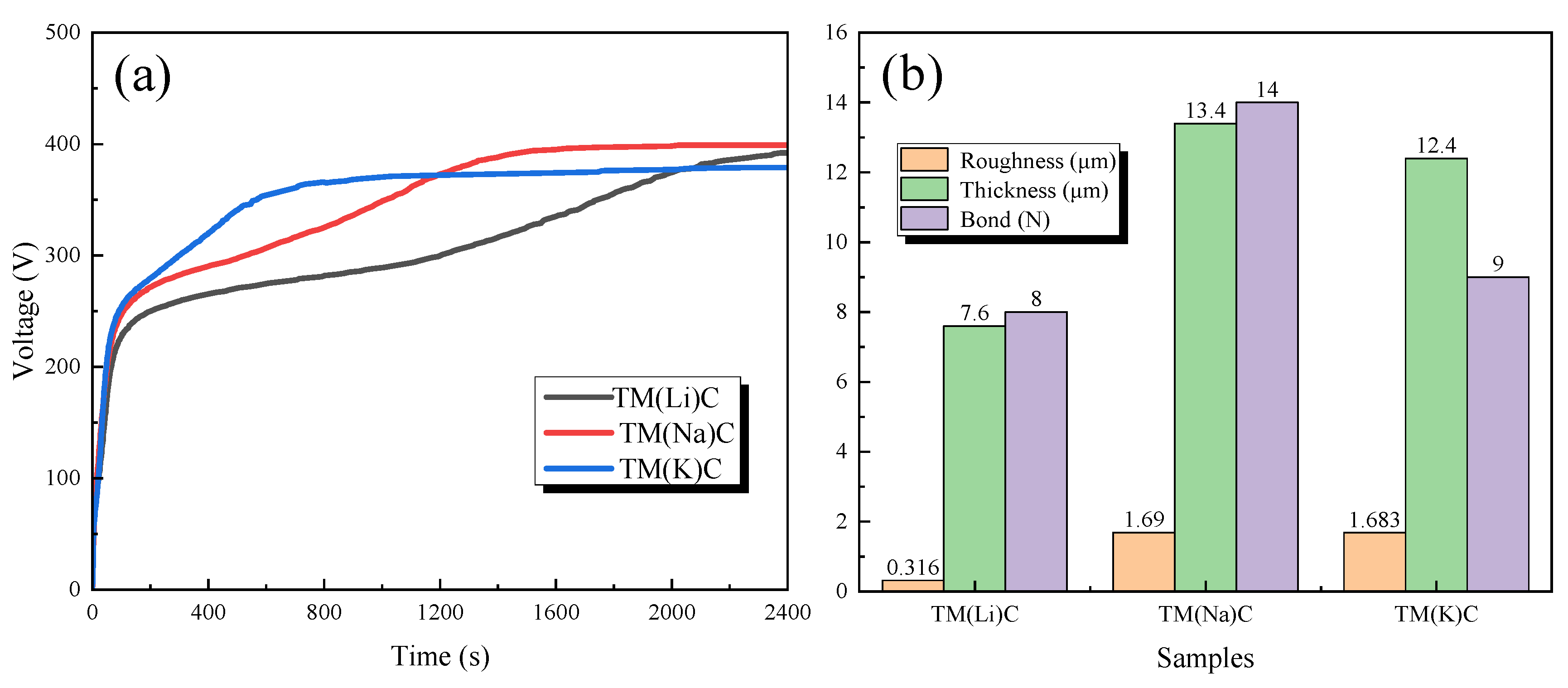
Figure 2.
SEM images and elemental distribution maps of micro-arc oxidation coatings fabricated on a TA1 substrate using Li2B4O7, Na2B4O7, and K2B4O7 electrolytes: (a1) TA1 substrate; (b1) TM(Li)C; (c1) TM(Na)C; (d1) TM(K)C; (a2–d2) magnified views of the corresponding regions.
Figure 2.
SEM images and elemental distribution maps of micro-arc oxidation coatings fabricated on a TA1 substrate using Li2B4O7, Na2B4O7, and K2B4O7 electrolytes: (a1) TA1 substrate; (b1) TM(Li)C; (c1) TM(Na)C; (d1) TM(K)C; (a2–d2) magnified views of the corresponding regions.
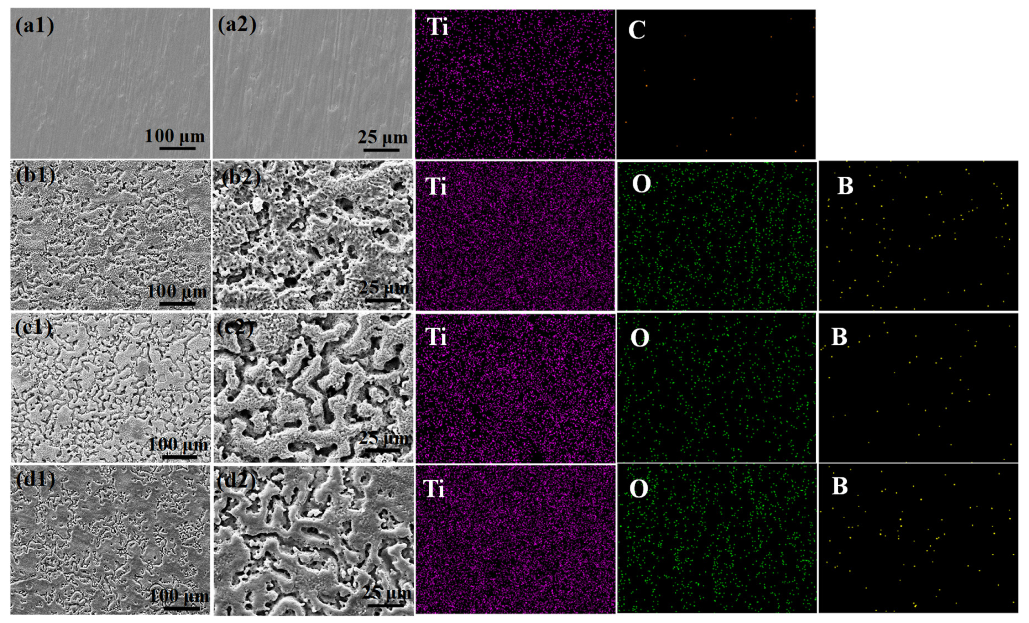
Figure 3.
Static contact angle measurements of different sample surfaces.
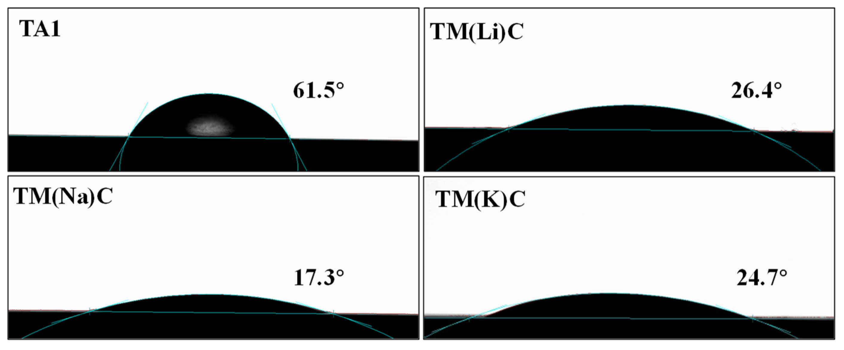
Figure 4.
XRD patterns of micro-arc oxidation coatings fabricated using Li2B4O7, Na2B4O7, and K2B4O7 electrolytes.
Figure 4.
XRD patterns of micro-arc oxidation coatings fabricated using Li2B4O7, Na2B4O7, and K2B4O7 electrolytes.
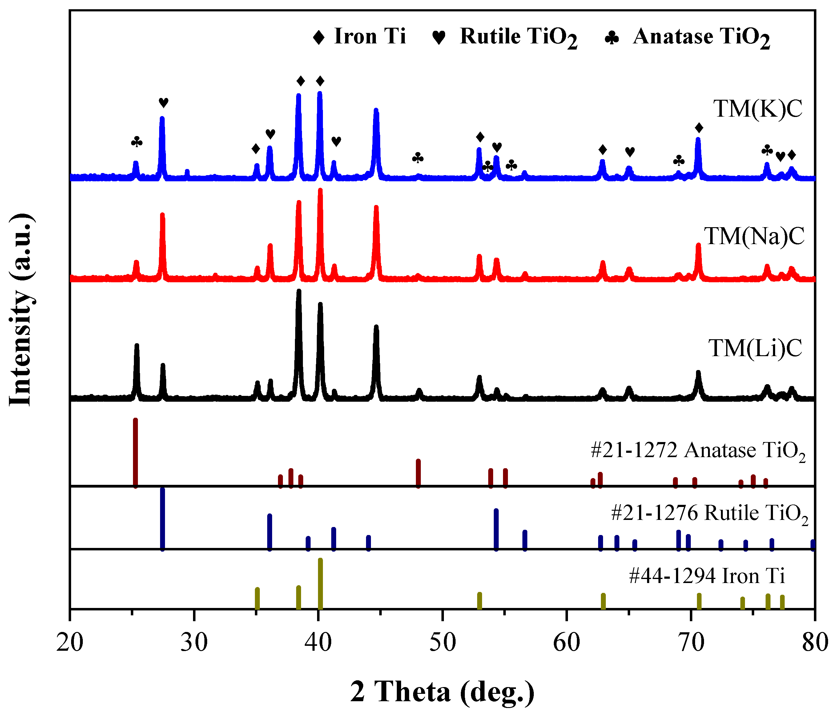
Figure 5.
XPS analysis results of micro-arc oxidation coatings fabricated using Li2B4O7, Na2B4O7, and K2B4O7 electrolytes (a) Full spectrum; (b) B 1s; (c) Ti 2p; (d) O 1s.
Figure 5.
XPS analysis results of micro-arc oxidation coatings fabricated using Li2B4O7, Na2B4O7, and K2B4O7 electrolytes (a) Full spectrum; (b) B 1s; (c) Ti 2p; (d) O 1s.
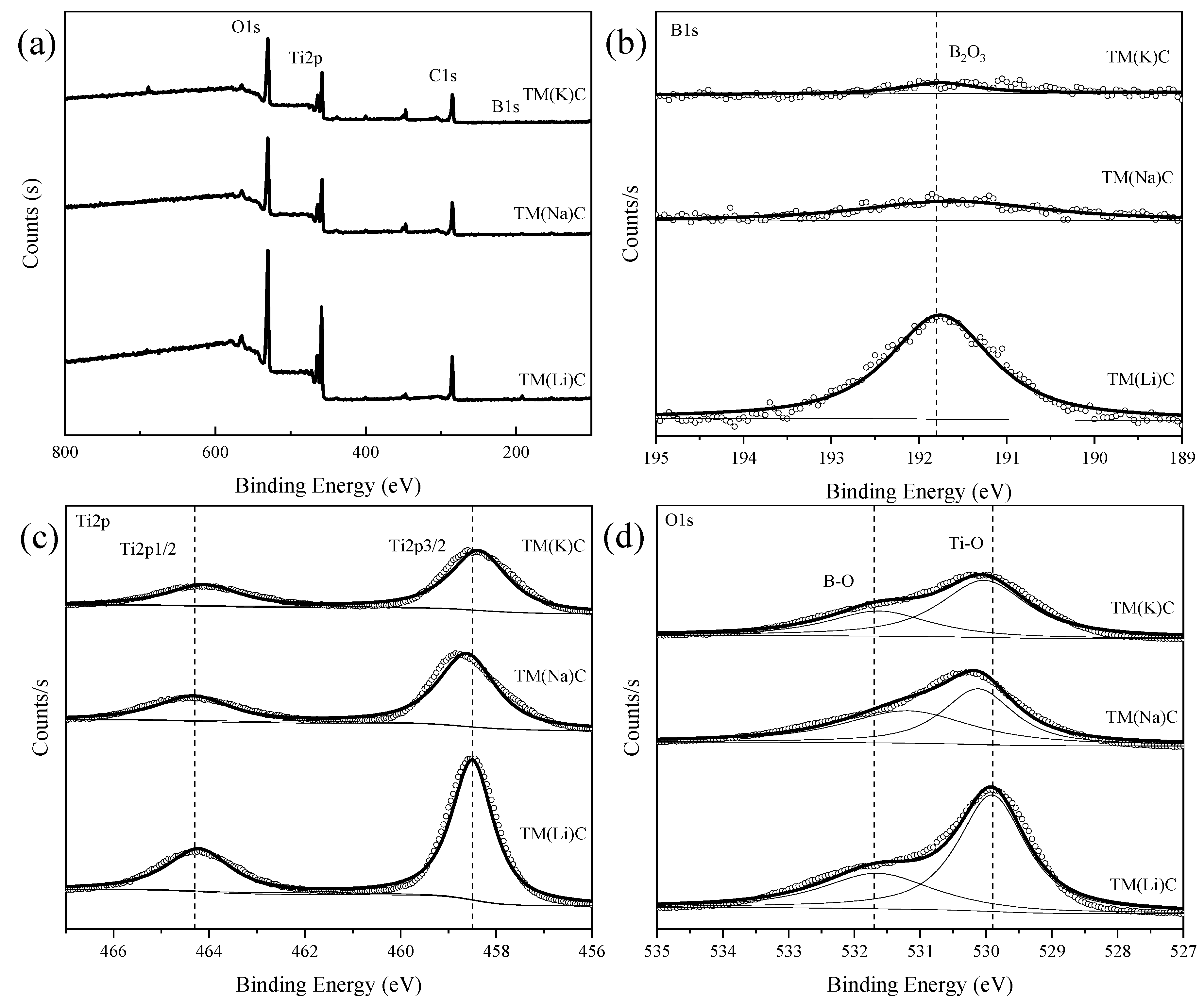
Figure 6.
Potentiodynamic polarization curves of the TA1 substrate and MAO coatings fabricated using Li2B4O7, Na2B4O7, and K2B4O7 electrolytes.
Figure 6.
Potentiodynamic polarization curves of the TA1 substrate and MAO coatings fabricated using Li2B4O7, Na2B4O7, and K2B4O7 electrolytes.
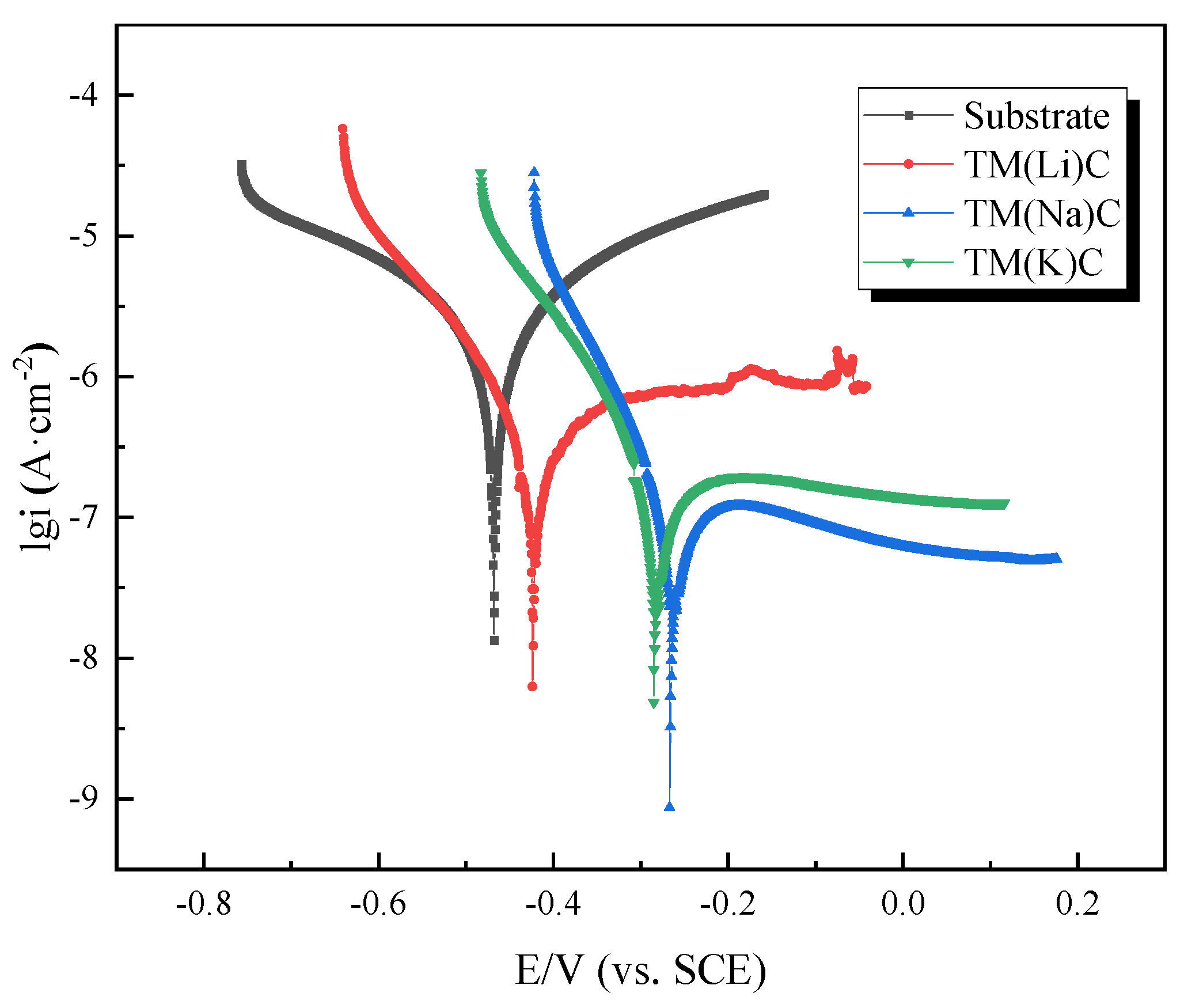
Figure 7.
Nyquist plots (a), impedance modulus curves (b), and phase angle curves (c) of the MAO coatings fabricated on the TA1 substrate using Li2B4O7, Na2B4O7, and K2B4O7 electrolytes.
Figure 7.
Nyquist plots (a), impedance modulus curves (b), and phase angle curves (c) of the MAO coatings fabricated on the TA1 substrate using Li2B4O7, Na2B4O7, and K2B4O7 electrolytes.
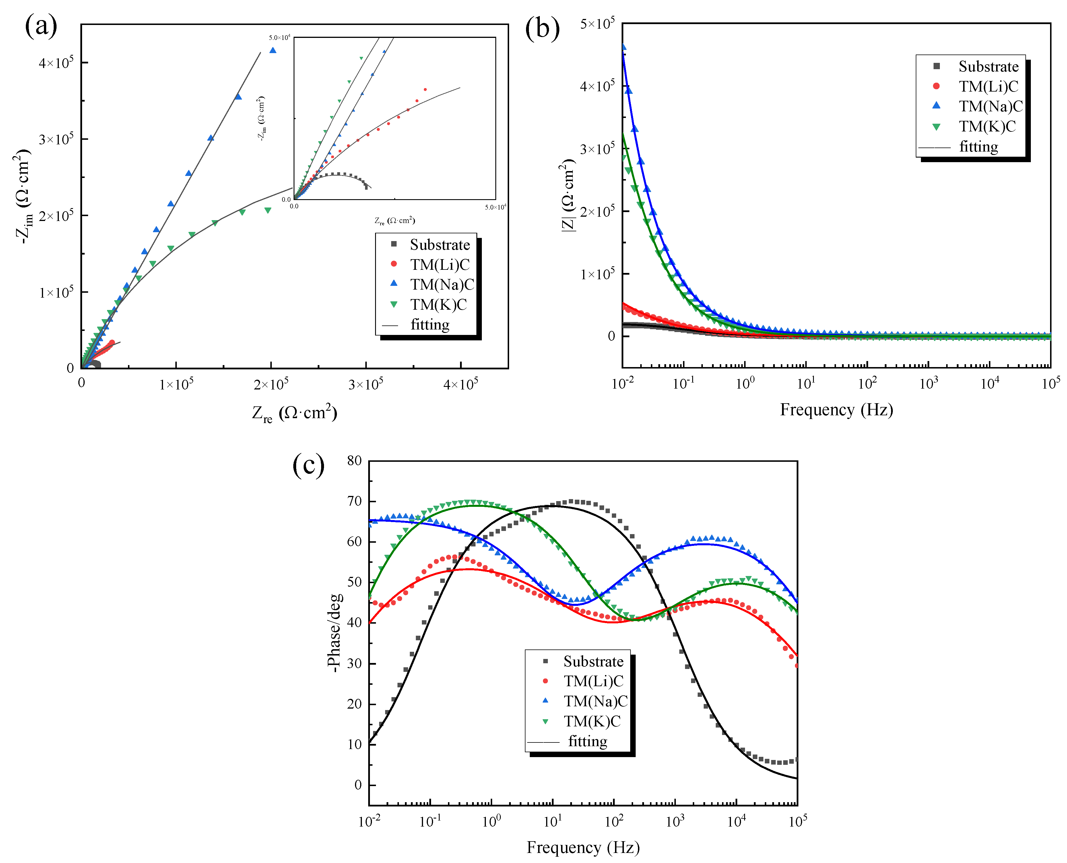
Figure 8.
Equivalent electrical circuits: (a) TA1 substrate; (b) TA1-MAO coating.
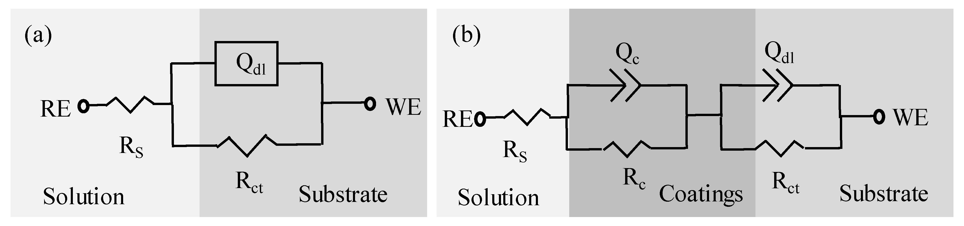

Table 1-1.
Chemical Composition of TA1 Titanium Alloy (wt.%) .
| Element | Fe | C | O | H | N | Ti |
| Content | 0.047 | 0.012 | 0.080 | 0.0004 | 0.0063 | Bal. |
Table 2.
EDS elemental composition of micro-arc oxidation coatings fabricated on the TA1 substrate using Li2B4O7, Na2B4O7, and K2B4O7 electrolytes.
Table 2.
EDS elemental composition of micro-arc oxidation coatings fabricated on the TA1 substrate using Li2B4O7, Na2B4O7, and K2B4O7 electrolytes.
| Samples | Mass percentage(wt.%) | Atomic percentage(at.%) | ||||
| Ti | O | B | Ti | O | B | |
| TA1 | 98.82 | -- | -- | 95.47 | -- | -- |
| TM(Li)C | 60.39 | 38.41 | 1.20 | 33.42 | 63.64 | 2.94 |
| TM(Na)C | 58.07 | 41.05 | 0.89 | 31.40 | 66.46 | 2.13 |
| TM(K)C | 60.88 | 37.56 | 1.56 | 33.78 | 62.39 | 3.83 |
Table 3.
Fitting parameters of potentiodynamic polarization curves for the samples tested in 3.5 wt.% NaCl solution .
Table 3.
Fitting parameters of potentiodynamic polarization curves for the samples tested in 3.5 wt.% NaCl solution .
| Samples | Ecorr(mV) | icorr(A·cm-2) | ba(mV) | bc(mV) | MPY |
| Substrate | -468.38 | 5.8027×10⁻⁶ | 472.70 | 542.89 | 4.634 |
| TM(Li)C | -412.50 | 1.5544×10⁻⁷ | 176.56 | 95.518 | 0.124 |
| TM(Na)C | -254.13 | 8.0435×10⁻⁸ | 9548.30 | 79.559 | 0.064 |
| TM(K)C | -272.39 | 8.4739×10⁻⁸ | 448.16 | 90.282 | 0.068 |
Table 4.
Fitting results of the AC impedance spectra for the specimens immersed in 3.5 wt.% NaCl solution.
Table 4.
Fitting results of the AC impedance spectra for the specimens immersed in 3.5 wt.% NaCl solution.
| Samples |
Rs Ω·cm2 |
Qc 10-6Ω-1·sn·cm-2 |
Qn 0<n<1 |
Rc Ω·cm2 |
Qdl 10-6Ω-1·sn·cm-2 |
Q-ndl 0<n<1 |
Rct 104Ω·cm2 |
| Substrate | 9.56 | -- | -- | -- | 8.889 | 0.7906 | 2.115 |
| TM(Li)C | 6.121 | 6.454 | 0.5774 | 295.6 | 8.36 | 0.6374 | 15.21 |
| TM(Na)C | 11.2 | 7.211 | 0.609 | 279.3 | 2.309 | 0.7733 | 55 |
| TM(K)C | 9.737 | 1.253 | 0.7484 | 427.6 | 5.155 | 0.625 | 31.96 |
Disclaimer/Publisher’s Note: The statements, opinions and data contained in all publications are solely those of the individual author(s) and contributor(s) and not of MDPI and/or the editor(s). MDPI and/or the editor(s) disclaim responsibility for any injury to people or property resulting from any ideas, methods, instructions or products referred to in the content. |
© 2025 by the authors. Licensee MDPI, Basel, Switzerland. This article is an open access article distributed under the terms and conditions of the Creative Commons Attribution (CC BY) license (http://creativecommons.org/licenses/by/4.0/).
Copyright: This open access article is published under a Creative Commons CC BY 4.0 license, which permit the free download, distribution, and reuse, provided that the author and preprint are cited in any reuse.


