
Submitted:
19 August 2025
Posted:
19 August 2025
You are already at the latest version
Abstract
Microbial fuel cells (MFC) are an innovative device in which the chemical energy stored in the organic waste can be efficiently converted to bioelectricity with the assistance of the metabolic catalysis by microorganisms. The membrane has a high influence on the performance of the MFC because a large portion of internal resistance of MFC is owed to the membrane. Cellulosic nanofibers have various characteristics among them; low thermal expansion, high aspect ratio, good optical and mechanical properties, high strengthening effect, renewability and biodegradability. Upon the use in MFC, nanocellulose film had a high power density of 136mW/m2, Compared to Nafion (control) with power density of 74mW/m2 at the same experiment condition. Nanocellulose film shows a high potential for application as a proton exchange membrane in MFC.
Keywords:
microbial fuel cell
; permeable electron membrane
; nanocellulose
Cellulose, a biopolymer, is the main component of all plant fibers and is created by repeating link of β-d- units linked together by β-1–4-linkages in a repeating unit known as cellubiose(Abdul Khalil, Davoudpour et al. 2014). The production of the cellulosic fibers in nano dimensions has been noted to have high mechanical characteristics and low density(de Mesquita, Donnici et al. 2010). The term ‘nanocellulose’ generally refers to cellulosic materials having at least one dimension in the nanometer range. Cellulosic nanofibers have various characteristics among them low thermal expansion, high aspect ratio which is defined as the length to diameter ratio, good optical and mechanical properties and high strengthening effect, renewability and biodegradability (Kalia, Dufresne et al. 2011). Nanofibrillar cellulose, cellulose nanofiber and cellulose nanofibrial are terms that refers to microfibrillated cellulose, and are the smallest structural unit of plant fiber (Abdul Khalil, Davoudpour et al. 2014) and they find great application in nanopapers which are a network constructed by high aspect ratio (beyond 100) intertwined nanofibrils and random surface nanofibril orientation (Henriksson, Berglund et al. 2008).
This research involved the development of a nanocellulose based film; glutadelhyde 0.1% was added as a crosslink, chemical and structural characterization was done using respective analysis technique. Proton exchange membrane performance was evaluated in a MFC (microbial fuel cells) using Shewanella oneidensis strain. Carbon cloth was used as electrode in this experiment.
Instruments, Materials and Methods
Materials and Reagents
Nanocellulose paper, NaOH, urea, DI water, Glutaradelhyde, H2SO4, Na2SO4, 75% ethanol. Plastic tubes, lactate, MgSO4 conc.(2.41g/20ml water), CaCl2(0.294g per 20mL water),water , M9- (Na2HPO4.12H2O , KH2PO4, NaCl, NH4Cl) Cathode Liquid-(KCL -Potassium Chloride, K3[Fe (CN)6 ] –Potassium hexacynoferrate (III), Na2HPO4.12 H2O -Disodium hydrogen phosphate dodeccahydrate, KH2PO4 –Potassium dihydrogen phosphate, H2O- Di-ionised Water ) LB- Tryptone, Yeast extract, Sodium chloride , Water- dionised water).
Experimental Section
Nanocellulose-Glu Membrane
For Cellulose film, the modified method of (Cai, Zhang et al. 2004) was used. The aqueous solution containing NaOH/urea/H2O of a 7:12:81 by weight ratio was used as the solvent of cellulose. 2ml glutaradelhyde (Glu) (0.1% concentration) was added to enhance interlinkage. The solvent was pre-cooled to below -10⁰C, and then 5g amount of cellulose was immediately added into it at ambient temperatures below 25⁰C. Cellulose was completely dissolved within 5 minutes with stirring at 3000rpm. The resultant cellulose solution was subjected to centrifugation at 8000rpm for ten minutes at 10⁰C to degas it. 3 ml of the resultant solution was put on top of a glass, and then rolled with a standard glass roller that maintained the thickness of the expected film. The glass with the solution was immersed in a coagulation bath composed of 15wt.-% H2SO4/10wt.-% Na2SO4 aqueous solution at about 10⁰C. The film was washed with dionised water several times to achieve (7.0) pH, and then dried on a stainless steel flat pan surface (Cai, Zhang et al. 2004).
MFC Set-Up and Voltage Analysis
A dual chamber MFC separated with Nanocellulose+ Glu as a proton exchange membrane was used in this experiment. Carbon cloth (2cmx3cm) was used for cathode and (1cmx2cm) for anode electrode. The anodic chamber suspension was composed of M9 (28.5ml), LB (1.5ml), lactate 30μl, 30ul MgSO4 conc., 30μl CaCl2 and bacteria (Shewanella oneidensis). All experiments for MFC were done in the clean chamber. Shewanella oneidensis MR-1 were grown in LB broth for 16 hours and harvested by centrifugation. The cathode was filled with 30ml cathode liquid 0.05mol/L (K3 [Fe (CN) 6] and KCl solution. The MFC operation started when a two kΩ external resistor was connected between the anode and the cathode. The power output and polarization curves were obtained by varying the external resistor when the current output reached steady-state The voltage (V) across the external resistor (R) was monitored by a digital multimeter (Zheng, Xu et al. 2015). Operating room temperature was maintained at 30⁰C. The experiment was done in three triplicates, and the statistics for the power output in voltage was generated using Statistical software, notably SPSS. Each experiment was run approximately 75 hours. Lactate 30μl was added after first 40 hours of operation, then added each time the voltage dropped to approximate 0.030V. The polarization curves were obtained by varying the external resistance (range 20KΩ, 10 KΩ, 8KΩ, 6KΩ, 4KΩ, 2KΩ, 1KΩ, 800Ω, 600Ω, 400Ω, 200Ω) in discrete steps and measuring the corresponding voltage drop.
Power/Current Density Calculation
The output was corrected in Voltage(V), Current (I) in amperes (A) was calculated using Ohm’s law ,I=V(voltage)/R, where V is the measured voltage in volts(V) and R is the known value of the external resistance load in ohms(Ω) power = voltage(V)*current(I), power density was voltage(V )*current(I)/anode area(A). Power (P) in watts(W) was calculated by multiplying voltage with current P=I x V (Winfield, Chambers et al. 2014).
Results and Discussion
Raman spectra is important in investigating sp2 carbon material(Shao, Wang et al. 2016), (Figure 7.1) shows the peaks in the 330-620cm-1 range, which are assigned to C-O,C-C,C-O-C,O-C-O deformations, the peaks at 990cm-1 is due to the C-C stretching. The peak at 1095cm-1 represents C-O ring stretching vibrations and C-O-C glycosidic bond stretching (Quero, Nogi et al. 2011). The bands in the 1374-1600 cm-1 are attributed to C-C-H, O-C-H, C-O-H, H-C-H and CH2 stretching vibrations. A strong band at 2990cm-1 which corresponds to CH stretching vibrations is observed(Salvi, Barud et al. 2012) (Shao, Wang et al. 2016).
Figure 1.1.
Raman spectra for Nanocellulose+Glu.
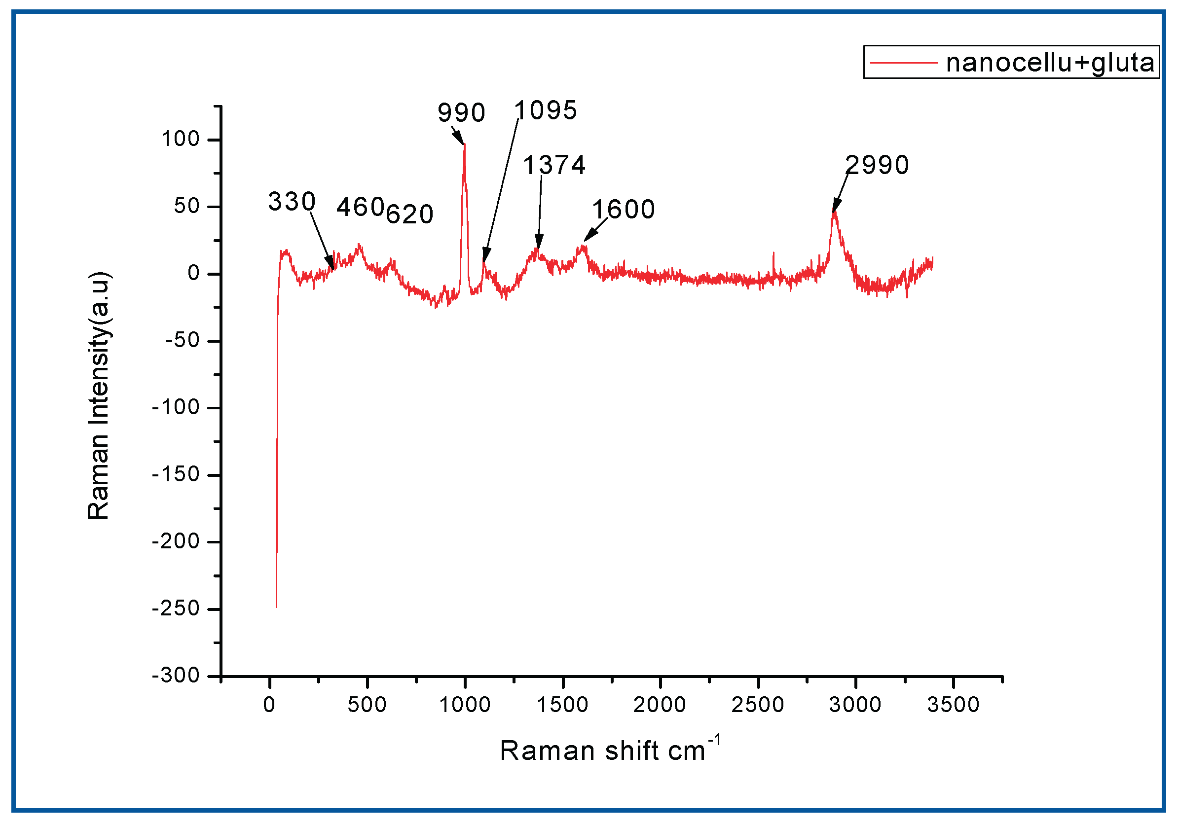

Table 1.1.
band assignment of FTIR spectra for Nanocellulose+ Glu film.
|
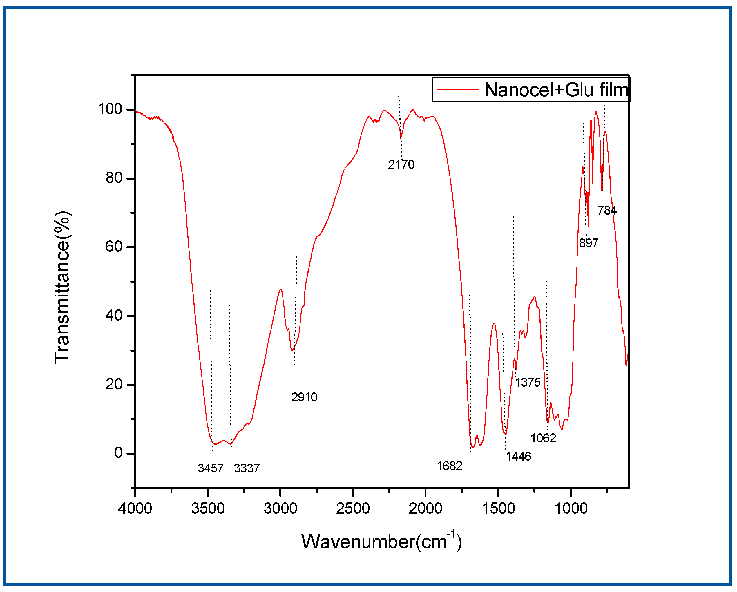
Band assignment of FTIR spectra for Nanocellulose+ Glu film Peak assignment Main observed bands (cm-1) Peak assignment in references 3457 (–OH) 3337 O-H stretching (O-H hydrogen bond) 2910 C-H stretching –CH2 (Shankar and Rhim 2016) 1682 (–C=O) 1446 CH2 bending (Shankar and Rhim 2016) 1062 C–O stretch in cellulose and hemicelluloses (Shankar and Rhim 2016) 897 Characteristic of β-glycosidic C–H deformation (Shankar and Rhim 2016) (Quero, Nogi et al. 2011) With a ring vibration |
Figure 1.2.
FT-IR for nanocellulose +Glu film.
The photo showing translucent photo of nanocellulose films modified with glutadelhyde (Figure 1.3a) and for the nanocellulose modified with glutadelhyde film upon use in the MFC (Figure 1.3b). Membrane was intact even upon long stay in the MFC, with no signs of degradation for a maximum of 50 hours in the MFC.
Figure 1.3.
Photos for Nanocellulose films.
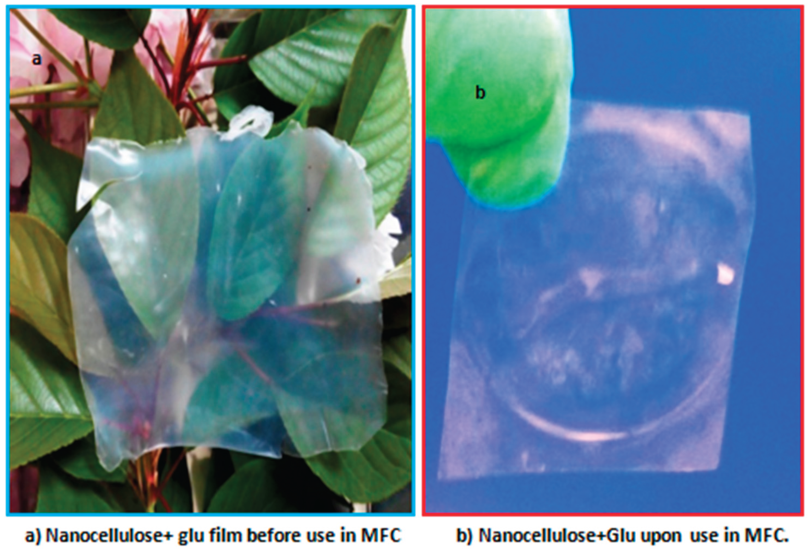
Figure 1.4.
XRD nanocellulose membranes.
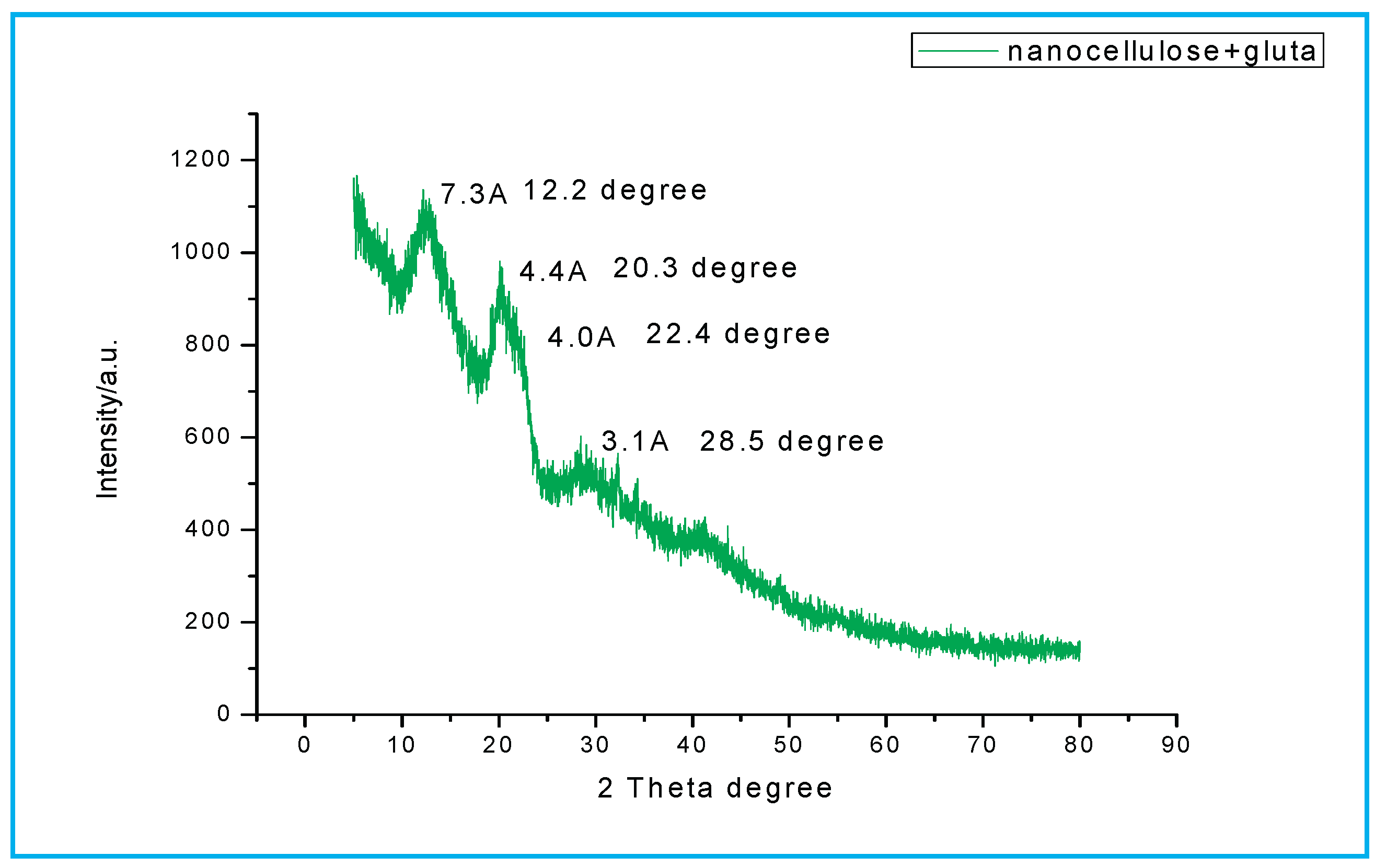
Nano- cellulose membrane peak was at 13.2⁰ at interplanar distance 6.2 Å, 20.3⁰ and 4.4 Å, 22.4⁰ with interplanar distance at 4.0 Å, and 28.5⁰ with interplanar distance at 3.1 Å. (Cai, Zhang et al. 2004, Peng, Gardner et al. 2013, Shankar and Rhim 2016).
Figure 1.5.
Performance of the nanocellulose+Glu film and Nafion in the MFC.
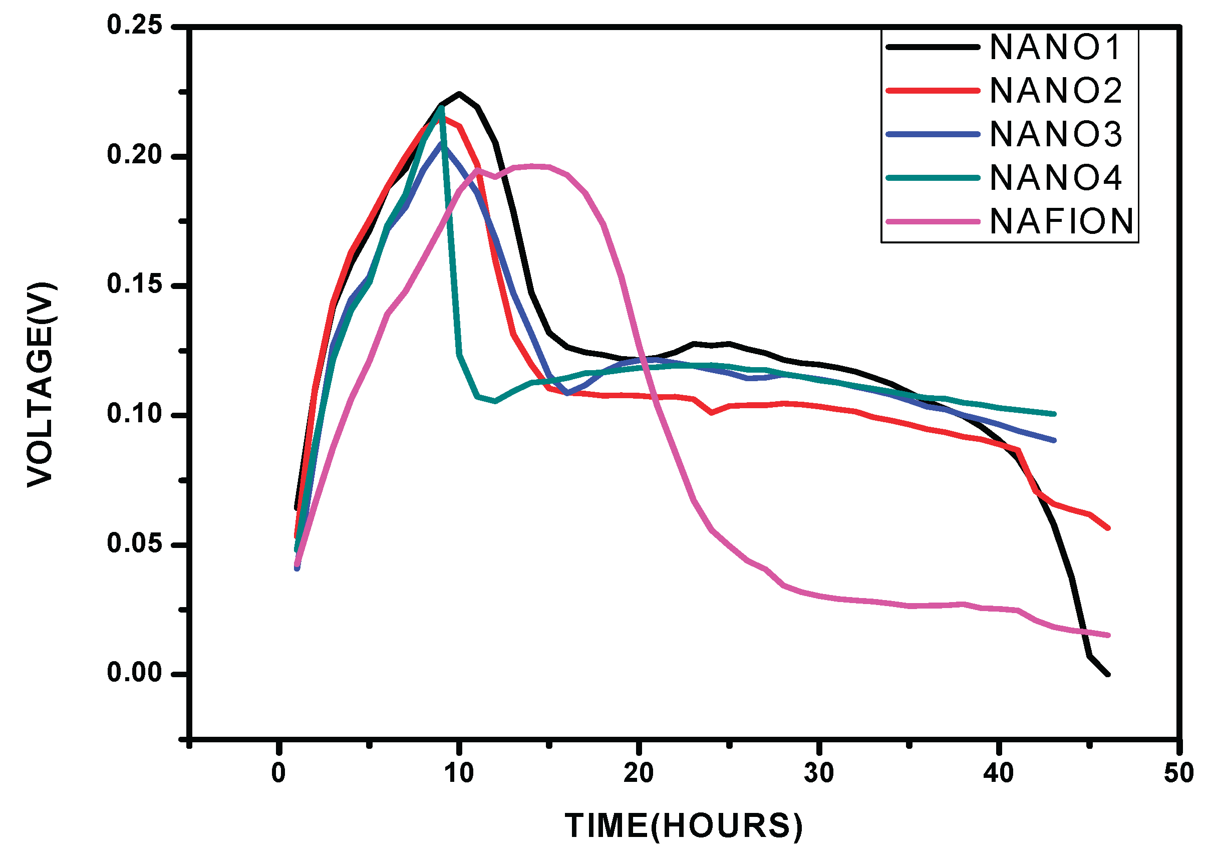
The voltage output for the nanocellulose membrane which was modified by glutaradelhyde was monitored in a microbial fuel cell, while using Shewanella oneidensis bacteria strain and carbon cloth electrode two kΩ resistor was applied all through in the voltage analysis.
Figure 1.6.
Polarization curves for Nanocellulose +Glu film.
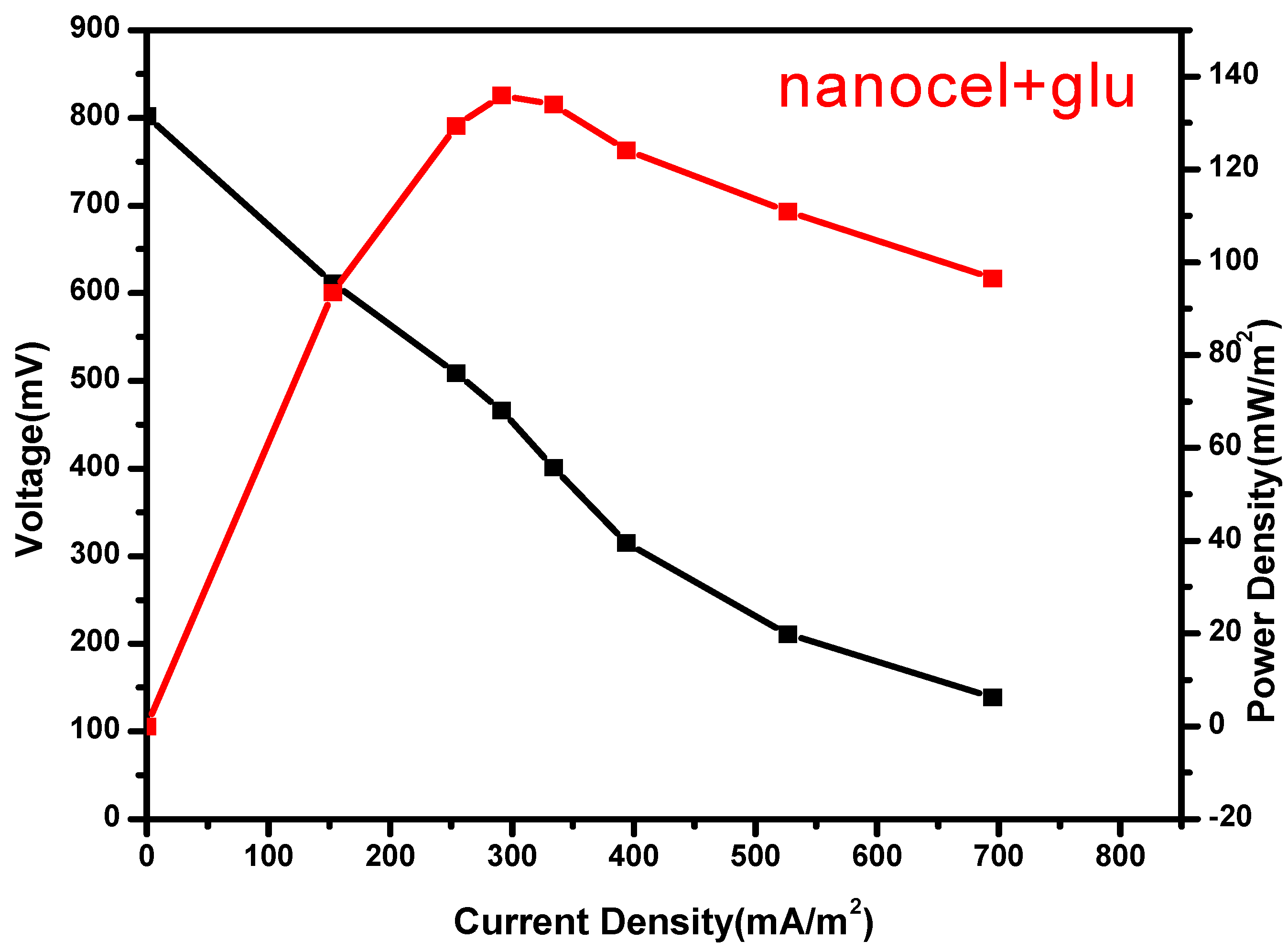
Figure 1.7.
Polarization curves for Nafion.
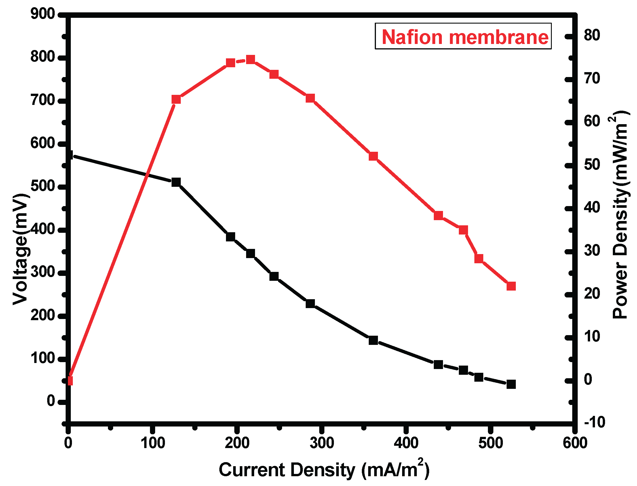
Table 1.2.
statistic table for nanocellulose+Glu and Nafion.
| Nanocellulose+ Glu Nafion |
|
Power density 136.0mW/m2 73.91mW/m2 Voltage range 0.028V 0.028V Voltage mean 0.211V 0.140V Standard deviation 0.014 0.015 Variance 0.00 0.00 |
There was observed an increase in power density with a decrease in applied external resistance until a peak, thereafter there was observed a decline which was attributed to activation and Ohmic losses. The cell design point of the MFC reactor was obtained at 200 ohm in both Nafion membrane and nanocellulose+Glutaradelhyde membrane (Singha, Jana et al. 2016). Upon the use in MFC nanocellulose+ Glu film had a high power density of 136.0mW/m2 (Figure 7.6) while Nafion (Figure 7.7) had 73.91 mW/m2
Nafion membrane had voltage mean of 0.140±0.015V, while nanocellulose+glu membrane had 0.211±0.014V, nanocellulose modified by glutadelhyde proof more economical and has high voltage output. The cost of a separator is a factor when a membrane is chosen and used in the MFCs. nanocellulose preparation in cheap. Commercial Nafion membranes are about $55per100cm2 (Tao, Sun et al. 2015). Nanocellulose films is known to have an excellent barrier properties against water vapor and oxygen (Kumar, Bollström et al. 2014) (Aulin, Gällstedt et al. 2010) low oxygen diffusion in the PEM is important factor for ion exchange in MFC (Leong, Daud et al. 2013).
Conclusion
Nanocellulose+Glutaradelhyde membrane shows a potential in developing low cost proton exchange membrane for microbial fuel cells membranes, this may be of great use in moving MFC research from laboratory to large scale field application. Further work is required to investigate proton conductivity and methanol permeability which also play key role in MFC membrane performance.
References
- Abdul Khalil, H. P. S., Y. Davoudpour, M. N. Islam, A. Mustapha, K. Sudesh, R. Dungani and M. Jawaid (2014). "Production and modification of nanofibrillated cellulose using various mechanical processes: A review." Carbohydrate Polymers 99(0): 649–665. [CrossRef]
- Aulin, C., M. Gällstedt and T. Lindström (2010). "Oxygen and oil barrier properties of microfibrillated cellulose films and coatings." Cellulose 17(3): 559–574. [CrossRef]
- Cai, J., L. Zhang, J. Zhou, H. Li, H. Chen and H. Jin (2004). "Novel Fibers Prepared from Cellulose in NaOH/Urea Aqueous Solution." Macromolecular Rapid Communications 25(17): 1558–1562. [CrossRef]
- de Mesquita, J. o. P., C. L. Donnici and F. V. Pereira (2010). "Biobased Nanocomposites from Layer-by-Layer Assembly of Cellulose Nanowhiskers with Chitosan." Biomacromolecules 11(2): 473–480. [CrossRef]
- Henriksson, M., L. A. Berglund, P. Isaksson, T. Lindström and T. Nishino (2008). "Cellulose Nanopaper Structures of High Toughness." Biomacromolecules 9(6): 1579–1585. [CrossRef]
- Kalia, S., A. Dufresne, B. M. Cherian, B. S. Kaith, Av, #233, L. rous, J. Njuguna and E. Nassiopoulos (2011). "Cellulose-Based Bio- and Nanocomposites: A Review." International Journal of Polymer Science 2011.
- Kumar, V., R. Bollström, A. Yang, Q. Chen, G. Chen, P. Salminen, D. Bousfield and M. Toivakka (2014). "Comparison of nano- and microfibrillated cellulose films." Cellulose 21(5): 3443–3456. [CrossRef]
- Leong, J. X., W. R. W. Daud, M. Ghasemi, K. B. Liew and M. Ismail (2013). "Ion exchange membranes as separators in microbial fuel cells for bioenergy conversion: A comprehensive review." Renewable and Sustainable Energy Reviews 28: 575–587. [CrossRef]
- Peng, Y., D. J. Gardner, Y. Han, A. Kiziltas, Z. Cai and M. A. Tshabalala (2013). "Influence of drying method on the material properties of nanocellulose I: thermostability and crystallinity." Cellulose 20(5): 2379–2392. [CrossRef]
- Quero, F., M. Nogi, K.-Y. Lee, G. V. Poel, A. Bismarck, A. Mantalaris, H. Yano and S. J. Eichhorn (2011). "Cross-Linked Bacterial Cellulose Networks Using Glyoxalization." ACS Applied Materials & Interfaces 3(2): 490–499. [CrossRef]
- Salvi, D. T. B., H. S. Barud, J. M. A. Caiut, Y. Messaddeq and S. J. L. Ribeiro (2012). "Self-supported bacterial cellulose/boehmite organic–inorganic hybrid films." Journal of Sol-Gel Science and Technology 63(2): 211–218. [CrossRef]
- Shankar, S. and J.-W. Rhim (2016). "Preparation of nanocellulose from micro-crystalline cellulose: The effect on the performance and properties of agar-based composite films." Carbohydrate Polymers 135: 18–26. [CrossRef]
- Shao, W., S. Wang, H. Liu, J. Wu, R. Zhang, H. Min and M. Huang (2016). "Preparation of bacterial cellulose/graphene nanosheets composite films with enhanced mechanical performances." Carbohydrate Polymers 138: 166–171. [CrossRef]
- Singha, S., T. Jana, J. A. Modestra, A. Naresh Kumar and S. V. Mohan (2016). "Highly efficient sulfonated polybenzimidazole as a proton exchange membrane for microbial fuel cells." Journal of Power Sources 317: 143–152. [CrossRef]
- Tao, H.-C., X.-N. Sun and Y. Xiong (2015). "A novel hybrid anion exchange membrane for high performance microbial fuel cells." RSC Advances 5(6): 4659–4663. [CrossRef]
- Winfield, J., L. D. Chambers, J. Rossiter, J. Greenman and I. Ieropoulos (2014). "Towards disposable microbial fuel cells: Natural rubber glove membranes." International Journal of Hydrogen Energy 39(36): 21803–21810. [CrossRef]
- Zheng, T., Y.-S. Xu, X.-Y. Yong, B. Li, D. Yin, Q.-W. Cheng, H.-R. Yuan and Y.-C. Yong (2015). "Endogenously enhanced biosurfactant production promotes electricity generation from microbial fuel cells." Bioresource Technology 197: 416–421. [CrossRef]
Disclaimer/Publisher’s Note: The statements, opinions and data contained in all publications are solely those of the individual author(s) and contributor(s) and not of MDPI and/or the editor(s). MDPI and/or the editor(s) disclaim responsibility for any injury to people or property resulting from any ideas, methods, instructions or products referred to in the content. |
© 2025 by the authors. Licensee MDPI, Basel, Switzerland. This article is an open access article distributed under the terms and conditions of the Creative Commons Attribution (CC BY) license (http://creativecommons.org/licenses/by/4.0/).
Copyright: This open access article is published under a Creative Commons CC BY 4.0 license, which permit the free download, distribution, and reuse, provided that the author and preprint are cited in any reuse.


