
Submitted:
19 August 2025
Posted:
19 August 2025
You are already at the latest version
Abstract
Heavy-load collaborative robots are increasingly used in fields such as the industrial handling and precision assembly. With the increase in the end load of the robotic arm and the acceleration of its movement speed, after the robotic arm completes a preset trajectory, due to factors such as inertia, the flexibility of the robotic arm's rods and the harmonic reducer materials at the joints, there will still be residual vibration for a period of time after the robotic arm reaches the end point. On the one hand, residual vibration will have an adverse impact on the high-precision and high-performance operations of the robotic arm, affecting the operation accuracy and thus the production quality. On the other hand, many operations need to wait until the robotic arm completely stops before proceeding. In practical applications, the time spent waiting for the robotic arm to stop significantly affects efficiency. Therefore, effectively suppressing residual vibration is crucial to improving the performance of the robotic arm.To solve the problem of end residual vibration in heavy-load six-axis collaborative robots, this paper conducts research on input shaping and the estimation of robot end vibration parameters in arbitrary poses. The vibration parameters of the robot end in arbitrary poses are estimated based on the established vibration parameter model. An input shaper is designed according to the derived design method of the input shaper, achieving a certain suppression effect on the residual vibration of the robot end. When the parameter identification error is small, the optimized vibration suppression effect reaches more than 70%, realizing rapid and robust vibration suppression. This research is of great significance for enhancing the application value of collaborative robots in precision manufacturing and heavy-duty handling.
Keywords:
heavy-load collaborative robot
; Input shaping
; active vibration suppression
1. Introduction
Collaborative robot, characterized by rapid deployment, flexible manufacturing, and human-robot collaboration, meets the needs of agile manufacturing in the manufacturing industry, such as multi-variety production, customization, flexibility, and rapid switching. Compared with traditional industrial robotic arms, collaborative robotic arms initially focused on lightweight application scenarios. However, with the industrial upgrading and development of electric vehicles, 3C manufacturing, precision manufacturing, and 5G communications, collaborative robots with a load exceeding 10Kg are increasingly being applied[1]. The annual market growth rate of collaborative robotic arms has exceeded 50%, far surpassing that of traditional industrial robotic arms, and has become a major trend in the development of robotic arms [2].
Due to factors such as inertia, the material flexibility of the robotic arm's links and joint harmonic reducers, there will still be a period of residual vibration after the robotic arm reaches the end poes. Effectively suppressing residual vibration is crucial to improving the performance of collaborative robots[3,4,5,6]. According to whether external input energy is required, the current vibration suppression methods can be divided into two major categories: passive control and active control[7].
Passive control does not require external input energy. It aims to suppress residual vibration by changing the structural and material characteristics of the system. Bandopadhya [8] utilized the characteristics of high strength and large damping of ionic polymer metal composites to effectively improve the residual vibration problem of flexible cantilever beams. Bajkowski [9] focused on the double-beam system and used intelligent particle structures to form a vibration absorber. Passive control requires additional hardware devices, which not only increases the cost of the robot, but also the system is usually designed for specific vibration frequencies.
Active control methods suppress residual vibrations by superimposing additional control signals through control algorithms to act on the system, resulting in faster response and better vibration suppression effects. Cannon [10] focused on serial flexible robotic arms, implemented feedback closed-loop using strain gauge sensors, designed a linear quadratic Gaussian controller to suppress residual vibrations. Preumont [11] elaborated on various active and passive control methods for residual vibration suppression. Meckl [12] used the common S-curve motion profile but optimized the selection of acceleration and deceleration phase durations. The most representative open-loop feedforward control method is input shaping method[13,14,15,16,17], which evolved from the Posicast control method proposed by Smith [18] in 1957 to suppress residual oscillations in electrical systems. Pao [19,20] developed a hybrid input shaping design method that interpolates between Zero Vibration (ZV), Zero Vibration Derivative (ZVD), and Extra-Insensitive (EI) shaper designs to achieve near-optimal performance. Tuttle [21] designed input shapers using zero placement in the discrete domain to reduce multi-modal vibrations. Zhao[22,23] proposed a zero-time-delay input shaping technique that adjusts input signals without introducing additional time delays. Huang et al. [24,25] focused on heavy-load cranes, using input shaping technology to eliminate load swings caused by human operator commands and employing feedback controllers to reduce the impact of wind gusts. This significantly improved the system's suppression speed for vibrations caused by inter-link coupling and external disturbances.
To achieve effective vibration suppression, it is necessary to obtain the natural frequency and damping ratio parameters of the robot end vibration[26]. Kenderi et al. [27] proposed an optimal observer based on the least square method and Kalman filtering for the identification of nonlinear mechanical systems. Masri et al. [28] proposed a neural network-based nonlinear dynamic system identification method and applied it to a damped Duffing oscillator under deterministic excitation, providing a high-fidelity mathematical model for structurally unknown nonlinear systems encountered in the field of applied mechanics. Juang[29] proposed an algorithm called the Eigensystem Realization Algorithm for identifying modal parameters and simplifying dynamic systems from test data. Combined with singular value decomposition technology, modal parameter identification is carried out to quantitatively identify system modes and noise modes, and it has been verified using experimental data from the Galileo spacecraft. Nadkarni[30], in order to predict the response of a structure when subjected to forces in the working environment, determined the dynamic characteristics of the structure through experimental modal analysis, obtained three modal parameters, namely natural frequency, damping, and modal shape, and performed numerical verification using the finite element software package Hypermesh 13.0. Doughty[31] discussed in detail the advantages and limitations of three nonlinear system identification techniques for cantilever beam analysis, based on the continuous-time differential equation model of the system, the relationships generated using the harmonic balance method, and the fitting of steady-state response data to amplitude and phase modulation equations.
This paper adopts the input shaping method to solve the problem of end residual vibration in heavy-load six-axis collaborative robots. This method realizes the suppression of residual vibration by adjusting the original input control signal with an input shaper composed of several pulse signals with different amplitudes and time delays to obtain a new input signal that acts on the system. A data-based method for estimating the residual vibration frequency and damping ratio of the robotic arm in arbitrary poses is proposed. A model from the robotic arm's joint angles and end load mass to the end vibration frequency and damping ratio is established, and the least square identification method is used to identify the model parameters. Finally, based on the estimated vibration parameters of the robotic arm's end in arbitrary poses, three input shapers are designed and applied to the control of the collaborative robotic arm, achieving a good suppression effect on the end residual vibration of the robotic arm in arbitrary poses. Unlike existing methods requiring pre-motion calibration, our approach enables real-time vibration parameter estimation for arbitrary poses, eliminating the need for trajectory pre-runs. The average suppression ratio is over 40%, and when the parameter identification error is small, the suppression effect reaches more than 70%.
2. Modeling and Parameter Estimation of Residual Vibration at the End of a Manipulator in Arbitrary Poses
2.1. Modeling of Residual Vibration at the End of a Manipulator
A 6-DOF serial manipulator can be approximated by a second-order system, and the transfer function of a typical second-order system is shown in Equation (1)
where is the undamped natural frequency of the system, and is the damping ratio of the system. When a unit impulse is applied at time 0, the response equation is the Laplace inverse transform of its transfer function, as shown in Equation (2)
A pulse with an amplitude of and a time delay of will excite residual vibration in the system, as shown in Equation (3)
The total response of the system is the sum of the responses induced by all pulses. Assuming there are pulses, the total response of the system is
Using trigonometric function formulas, Equation (4) is expanded and slightly rearranged into the form shown in Equation (5)
where is the damped natural frequency of the system, and its relationship with the undamped natural frequency is
Using the trigonometric auxiliary angle formula, Equation (6) can be further sorted out to obtain Equation (7)
where .
To describe the effect of input shaping in the system, a residual vibration variable is introduced. Its physical meaning is the ratio of the system vibration amplitude without shaping to that with shaping at the moment when the last pulse of the input shaper is applied. This variable is also called the residual vibration percentage, which is the ratio of Equation (2) to Equation (7), and the simplified form is shown in Equation (8):
For a heavy-load collaborative robotic manipulator, to achieve the effect of eliminating residual vibration, it is necessary to design a series of appropriate and so that the residual vibration percentage is as close to 0 as possible.
Figure 1 shows the acceleration signal at the end of the manipulator measured by an accelerometer when the manipulator reaches the end point after moving along a certain trajectory. From Equation (3) and Figure 1, it can be seen that the mathematical form of the residual vibration excited at the end of the robotic arm by a pulse with an amplitude of and a time delay of is approximately a damped harmonic vibration, which is expressed by the impulse response equation (9)
where is the initial time. As shown in Figure 1, only two data points and () are needed to determine and the damping ratio . can be directly obtained from (10),
After obtaining the natural frequency , the damping ratio is then calculated. For convenience of calculation, and can be taken as two adjacent peak points, where the sine factor of the peak points is equal to 1, meaning only the amplitude part needs to be considered. Dividing by gives Equation (11):
Substituting the natural frequency obtained from Equation (10) into Equation (11), the damping ratio can be solved by (12)
Due to the interference from changes in external conditions and the influence of high-order vibration modes of the robotic arm during operation, the signals measured by the acceleration sensor for vibration measurement may have certain accidental errors, and the end vibration parameters also vary under different poses. As a feedforward control method, vibration suppression based on input shaping requires obtaining the vibration parameters of the system in advance. The most direct way to obtain the vibration parameters is to run the required trajectory of the robotic arm in advance and calculate the vibration parameters at the end point of the trajectory based on the vibration signal when it reaches there. However, in practical applications, it is impossible to run the robotic arm in advance before each movement, so it is necessary to estimate the vibration parameters.
2.2. Parameter Estimation of Residual Vibration at the End of a Robotic Arm in Arbitrary Poses
When controlling the robotic arm to complete a task, the end point of each segment of its motion trajectory is a specified input, that is, the joint angles of the six joints are known; the load carried by the end of the robotic arm can also be measured before each movement. All input variables are integrated into a column vector , as shown in Equation (13)
whererepresents the joint angles of the robotic arm, which is a six-dimensional column vector; is the weight of the load carried by the end of the robotic arm; the vibration parameters to be estimated are the natural frequency and the damping ratio , which are denoted as a column vector .
If the robotic manipulator at each moment is equivalent to an ideal flexible body with uniform texture, according to the Euler-Bernoulli beam theory, its natural frequency has a quadratic relationship with the length of the end from the fixed axis, while the end distance has a trigonometric function relationship with each joint angle. A quadratic polynomial model is established between the input composed of joint angles and end loads, and the output composed of end vibration frequency and damping ratio, as shown in (14). For the sake of concise description, the load mass is denoted as ,
whereanddenote the coefficients of the linear term ; and denote the coefficients of the quadratic term and coupling term; and denote the deviations between the approximate model and the actual values. Both the system's natural frequency and damping ratio contain 1 constant term, 7 linear terms , 7 quadratic terms , and 21 cross terms , which can be written in matrix form as (15):
In the equation (15),represents the coefficient matrix, which is a matrix;represents the input variable, which is a 36-dimensional column vector containing a constant term, linear terms, quadratic terms, and cross terms.
In this paper, the least square method is used to identify the parameters of the coefficient matrix . Assuming that there areobserved data points obtained through experimental measurement, a target function is first constructed as the sum of squared errors between the predicted outputand the actual output.
For convenience of processing, all input variables in the measured data are stacked into an overall input matrix , which is an matrix,
All output variables are stacked into an overall output matrix , which is an matrix shown in (18),
The objective function can be re-expressed, and the least squares problem is obtained,
The symbol represents the Frobenius norm, which is the square root of the sum of the squares of all its elements; expanding the objective function gives,
According to the principle of least squares, to minimize the objective function , it is necessary to take the derivative of matrixand set the derivative to zero as shown in (21),
Finally, the estimated coefficient matrix of the manipulator in any poses is obtained by (22),
3. Active Suppression of Residual Vibration of Manipulators Based on Input Shapers
3.1. ZV Input Shaper
Input shaping is an open-loop control method that shapes the input signal through a pulse sequence diagram to achieve rapid suppression of residual vibrations in the system. The frequency domain expression of the input shaper is shown in Equation (23),
In the Equation (23), represents the amplitude of the pulse sequence; represents the time delay of the pulse sequence; represents the number of pulses contained in the input shaper. It can be seen from the mathematical expression of the input shaper that designing the input shaper is to determine the number of its pulses as well as the time delay and amplitude of each pulse. In this paper, three methods, namely ZV, ZVD and EI, are respectively used to design the input shaper, and their advantages and disadvantages in the application of heavy-load cooperative manipulators are analyzed. The ZV shaper has the following form,
As can be seen from Equation (8), to completely eliminate residual vibration, the residual vibration percentage can be set to 0. By observing the composition of , it can be known that means making the two squared terms under the square root zero respectively, that is, as shown in Equation (25),
Since the ZV shaper contains only two pulses (i.e.,), the left-hand side of each equation in Equation (25) is the sum of two terms,
The Equation (26) obviously has infinitely many solutions. To obtain a unique solution, there needs some constraint conditions. To minimize the time required for vibration elimination, the shaper can be made to start acting from time 0, i.e., . This constraint is also called the time-optimal constraint. To ensure that the target position of the system remains unchanged, the amplitudes of the pulses of the shaper are required to satisfy the constraint as shown in Equation (27)
This constraint is also referred to as the amplitude constraint. By combining Equation (26) and Equation (27), and substituting into them, the ZV shaper can be solved as Equation (28),
3.2. ZVD Input Shaper
When the model parameters of the system are accurately known, the ZV shaper can completely eliminate residual vibrations within half a vibration period. However, when the model parameters are not precisely known, the ZV shaper cannot suppress residual vibrations within the ideal time because it fails to effectively cancel the zeros of the system. To improve the vibration suppression effect of the input shaper under the condition of uncertain natural frequency parameters of the system, a constraint condition on the residual vibration percentage is introduced, and a ZVD input shaper with multiple zeros configured for the shaper is proposed. Treating the natural frequency as an independent variable and the residual vibration percentage as a function of the natural frequency, denoted as , to configure multiple zeros for the shaper means that the derivative of the residual vibration percentage at the actual natural frequency should be zero. Then, the newly introduced constraint condition is as shown in Equation (29),
whererepresents the actual undamped natural frequency. The ZVD shaper contains three pulses, i.e., , and the specific amplitude constraint is
By combining Equation (29) and (30), and substituting the time constraint into them, the ZVD shaper can be solved as Equation (31) ,
where .
3.3. EI Input Shaper
When the heavy-load cooperative manipulator is working, the parameters identified in advance will change, making it impossible for the model to be completely accurate at all times. By using the EI input shaper, an allowable residual vibration amount is specified, and it is only required that the residual vibration of the system at the natural frequency is less than or equal to , as shown in Equation (32),
By combining Equation (32), the amplitude constraint (30) and , the parameters of each pulse of the EI shaper can be solved as following [32],
where . The effect of the EI input shaping also varies when takes different values.
4. Experiments and Analysis
4.1. Experiment on Vibration Suppression of a Single-Joint Manipulator
In this section, a single-joint manipulator is used to verify the effect of input shapers on suppressing residual vibrations, and the vibration suppression effect, robustness, and time required for vibration suppression of various input shapers are compared. The experimental equipment is shown in Figure 2. The single-axis manipulator is driven by a joint motor to actuate a steel ruler with a certain degree of flexibility. An acceleration sensor is installed at the end of the steel ruler, through which the vibration signal can be measured. In this experiment, the joint motor will be controlled to rotate by a certain angle, and after reaching the end position, the steel ruler will have residual vibrations due to inertia. The joint motor used in this paper is the one used in the CR series manipulators of Dobot robotics, which can be simulated and controlled by a Speedgoat controller.
A step signal with an amplitude of 45°is given to the robot joint. The vibration signal measured by the accelerometer installed at the end of the steel ruler is shown in Figure 3 (a). Using Equations (28) ,(31) and (33), the frequency of the end vibration is calculated to be 17.872 Hz, and the damping ratio is 0.0089. Based on the derivation in Section 3.1, ZV, ZVD, and EI shapers can be designed as shown in the equations:
The acceleration data of the single manipulator under the action of the three input shapers are shown in Figures 3 (b), (c), and (d) respectively. By comparison in Table I, the maximum amplitude of the end without input shaping is 1.263, while the maximum amplitudes under the action of the ZV, ZVD, and EI shapers are 0.51, 0.393, and 0.375 respectively, which are reduced by 59.7%, 68.9%, and 70.3% accordingly. It can be seen that the ZV, ZVD, and EI shapers all have inhibitory effects on residual vibrations. Among them, the ZVD shaper and EI shaper have slightly better vibration suppression effects than the ZV shaper, and the EI shaper performs slightly better than the ZVD shaper. In terms of response time and vibration suppression time, the ZV shaper takes 0.255 s to suppress the residual vibration to below 10%, the ZVD shaper takes 0.37 s, and the EI shaper takes 0.395 s. It can be observed that after adding the shapers, the response time of the system increases significantly, as the shapers introduce a certain time delay into the system. In comparison, the ZV shaper can suppress the residual vibration to a relatively low level in a shorter time, while the ZVD and EI shapers require a longer time. The experimental videos of the single-axis robot in four forms are shown in the appendix.

Table 1.
Vibration suppression effect of single-joint manipulator.
| Items | Maximum Amplitude) | Optimization Effect |
|---|---|---|
| NO Input Shaper | 1.263 | / |
| ZV Input Shaper | 0.510 | 59.7% |
| ZVD Input Shaper | 0.393 | 68.9% |
| EI Input Shaper | 0.375 | 70.3% |
4.2. Experiment on Heavy-Load Six-Axis Collaborative Robot
4.2.1. Introduction to the Experimental Platform
Figure 4 shows the heavy-load (16kg load) six-axis collaborative manipulator, and its basic parameters are shown in Table 2. In the manipulator control program, after initialization and related calculations, the program is divided into two threads, the manipulator motion control thread and the sensor data receiving thread. In terms of sensors, first of all, since the maximum residual vibration frequency at the end of some measured points of the Dobot robotics CR16 manipulator is approximately 75 Hz, in order to obtain a relatively accurate vibration waveform, the sampling frequency should preferably be no less than 40 times the system vibration frequency. That is, the selected accelerometer sampling rate and data return frequency need to be no less than 3000 Hz. Secondly, since the roughly measured maximum vibration acceleration of the Dobot robotics CR16 manipulator when reaching the end point at 70% of the maximum operating speed is about 1g, the range of the selected sensor should be no less than ±2g. In addition, to make the experimental results more accurate, sensors with small resolution and low noise should be selected as much as possible.
4.2.2. Vibration Parameter Identification for Arbitrary Poses
Since the reading of the accelerometer can be performed in a different thread of the same program as the manipulator control, the accelerometer data and the robot joint encoder signals can be collected simultaneously while the manipulator is in motion. When the manipulator moves with a load, it can automatically run through all the points that need to be measured, with sufficient time intervals reserved between each point to allow the residual vibration at the end to stop completely. Since the vibration parameters of the manipulator are significantly more affected by axes 2, 3, and 4 than by other axes, the joint angle intervals of these three axes are subdivided into smaller increments. After acquiring a set of operation data, the data segments corresponding to all points are identified, and the vibration frequency and damping ratio of each are calculated using the method described in Section 2.1. For example, point A in Figure 5 is extracted separately. In the experiment to obtain the estimated model, due to symmetry, the movement of axes 1 and 6 obviously does not affect the vibration characteristics of the manipulator, so they are not subdivided. The 90°movement range of axis 2 is subdivided into intervals of 15°, resulting in a total of 7 joint angle positions. The 180°movement ranges of axes 2, 3, and 4 are also subdivided into 15°intervals; after excluding angles that are inaccessible due to structural constraints, there are 10 joint angle positions for each axis. In addition, before conducting the experiment, the Cartesian coordinates of the end-effector are solved using the forward kinematics of the manipulator, and its movement is restricted to a safe range. When the load is fixed, the manipulator runs once to traverse all end points and collect data, resulting in a total of 2328 sets of data.
Some points are selected to calculate their vibration parameters using the estimation model, and the errors are computed by comparing these parameters with those measured experimentally at the same points. Table 3 shows the observation results of some points, where is the estimated value of the system's natural frequency; is the experimentally measured value of the system's natural frequency; is the estimation error of the system's natural frequency; is the estimated value of the system's damping ratio; is the experimentally measured value of the system's damping ratio; and is the estimation error of the system's damping ratio.
4.2.3. Active Suppression of Manipulator in arbitrary poses
For input shaping technology, it is only necessary to shape the control signal before it is input to the actuator. In this paper, the built-in position controller of the Dobot CR16 manipulator is used. In the joint space, the position signal is input into the shaper and convolved with the shaper to form a new control signal. The design flow in the joint space is shown in Figure 6.
Figure 7 and Table 4 show that the three input shaping methods (ZV, ZVD, and EI) can all exert a certain inhibitory effect on the residual vibration at the end of the six-axis collaborative manipulator. Without input shaping, the maximum amplitude at the end-effector is 0.4692 g. With the ZV, ZVD, and EI shapers applied, the maximum amplitudes are 0.3155 g, 0.1849 g, and 0.1825 g respectively, representing reductions of 32.8%, 60.6%, and 61.1% in amplitude. It can be seen that the ZV, ZVD, and EI shapers all have inhibitory effects on residual vibration. Among them, the ZVD and EI shapers exhibit better vibration suppression performance than the ZV shaper, with the EI shaper performing slightly better than the ZVD shaper.In terms of response time and vibration suppression time, the ZV shaper takes 0.13s to suppress residual vibration to below 10%, the ZVD shaper takes 0.19s, and the EI shaper takes 0.17s. This indicates that after adding a shaper, the system's response time increases significantly, meaning the shaper introduces a certain time delay into the system. In comparison, the ZV shaper can suppress residual vibration to a relatively low level in a shorter time, while the ZVD and EI shapers require a longer time.
Table 5 presents the vibration suppression effects of the ZV, ZVD, and EI shapers designed respectively using the parameters estimated in Table 3. The experimental results show that all three input shaping methods (ZV, ZVD, and EI) can exert a certain inhibitory effect on the residual vibration at the end-effector of the six-axis collaborative manipulator. When the parameter estimation error is relatively large, the vibration suppression effect of the ZV shaper decreases significantly, while the ZVD and EI shapers perform slightly better. A further comparison with Table 3 reveals that the more accurate the parameter estimation, the better the effect of the input shaper on suppressing residual vibration. When the parameter identification error is small, the average suppression effect is over 40%, and especially when the parameter identification error is small, the suppression effect reaches more than 70%.
5. Conclusions
To address the issue of residual vibration at the end-effector of heavy-load six-axis collaborative robots in arbitrary poses, this paper conducts research on the modeling of the manipulator end vibration model, the estimation of manipulator vibration parameters in arbitrary poses, and carries out active vibration suppression experiments on residual vibration at the end of heavy-load six-axis collaborative robots in arbitrary poses based on ZV, ZVD, and EI shapers. The following achievements have been made: (1) The mathematical forms of input shaping methods are derived, including the design and robustness analysis of several common input shapers. A single-axis experimental platform is designed, and simulation and physical experiments are conducted to verify the effect of input shaping methods on suppressing residual vibration, while comparing the effects and characteristics of several input shapers. (2) Considering that the end vibration parameters of the robot vary under different poses and that it is impossible to run the robot in advance before each movement, this paper establishes a model between the robot joint angles, end load mass, and end vibration parameters, and adopts the least squares identification method for parameter identification. (3) Based on the established vibration parameter model, the vibration parameters of the robot end in arbitrary poses are estimated. Input shapers are designed according to the derived input shaper design method, and then the six-axis collaborative robot is controlled based on its kinematic model, achieving a certain suppression effect on the residual vibration at the robot end. The average suppression effect is over 40%, and especially when the parameter identification error is small, the suppression effect reaches more than 70%.
Author Contributions
Conceptualization, R.S. and Y.L.; methodology, Z.L.; software, S.F. and R.S.; validation, R.S.; formal analysis, Z.L.; investigation, R.S.; resources, Z.L.; data curation, Z.L..; writing—original draft preparation, S.F.; writing—review and editing, Z.L.; visualization, Z.L.; supervision, Y.L.; project administration, Y.L.; funding acquisition, Y.L. All authors have read and agreed to the published version of the manuscript.
Funding
This work was funded by (1)University-level Project of Shenzhen Polytechnic University, "Research on Key Technologies of Motion Control for Dual-arm Assembly Robots with Flexible Components in 3C Industry" (6022312001K);(2)University-level Project of Shenzhen Polytechnic University, "Study on Coupling Characteristics and Decoupling Control Mechanism of Pose Contour Error in Multi-axis Servo Systems" (6022310021K).
Institutional Review Board Statement
Not applicable.
Informed Consent Statement
Not applicable.
Data Availability Statement
The data presented in this study are available on request from the corresponding author. The data are not publicly available as the study will continue on this basis.
Acknowledgments
The authors are grateful to Dobot Robotics for their help in heavy-load collaborative robot experimental platform.
Conflicts of Interest
The authors declare no conflict of interest.
References
- Aliev K, Antonelli D. Proposal of a monitoring system for collaborative robots to predict outages and to assess reliability factors exploiting machine learning[J]. Applied Sciences, 2021, 11(4): 1621. [CrossRef]
- Liu L, Guo F, Zou Z, et al. Application, development and future opportunities of collaborative robots (cobots) in manufacturing: A literature review[J]. International Journal of Human–Computer Interaction, 2024, 40(4): 915-932. [CrossRef]
- Xiang Q, Chen C, Jiang Y. Vibration Suppression of Collaborative Robot Servo with Dual Encoders[J]. Applied Sciences, 2025, 15(5): 2548. [CrossRef]
- Han X, Wu K, Hui N. Co-Optimization of Vibration Suppression and Data Efficiency in Robotic Manipulator Dynamic Modeling[J]. Applied Sciences, 2025, 15(14): 7679. [CrossRef]
- Wang G, Fang S, Xu Q. Robot Joint Vibration Suppression Method Based on Improved ADRC[J]. Applied Sciences, 2025, 15(10): 5476. [CrossRef]
- Xiang Q, Chen C, Jiang Y. Vibration Suppression of Collaborative Robot Servo with Dual Encoders[J]. Applied Sciences, 2025, 15(5): 2548. [CrossRef]
- Min F, Cai Y, She Y, et al. Robot collisions classification based on variational mode decomposition of vibration measurements[J]. IEEE Transactions on Instrumentation and Measurement, 2024, 73: 1-16. [CrossRef]
- BANDOPADHYA D D, K. Active Vibration Suppression of a Flexible Link Using Ionic Polymer Metal Composite [C] // 2006 IEEE Conference on Robotics,Automation and Mechatronics,Bangkok, Thailand,2006 :1-6.
- BAJKOWSKI J M,DYNIEWICZ B,BAJER C, I. Semi-Active Damping Strategy for Beams System with Pneumatically Controlled Granular Structure [J].Mechanical Systems and Signal Processing,2016,70-71 :387-396. [CrossRef]
- CANNON R H,SCHMITZ, E. Initial Experiments on the End-Point Control of aFlexible One-Link Robot[J]. The International Journal of Robotics Research,1984,3(3):62-75.
- PREUMONT, A. Vibration Control of Active Structures [M]. Brussels, Belgium :Springer-Verlag Berlin Heidelberg,2011:49.
- MECKL P,ARESTIDES, P. Optimized S-Curve Motion Profiles for MinimumResidual Vibration[C] // Proceedings of the 1998 American Control Conference (ACC):Vol 5,Philadelphia, USA,1998:2627-2631.
- Kuck E, Sands T. Space robot sensor noise amelioration using trajectory shaping[J]. Sensors, 2024, 24(2): 666. [CrossRef]
- Magistri F, Marcuzzi R, Marks E, et al. Efficient and accurate transformer-based 3d shape completion and reconstruction of fruits for agricultural robots[C]//2024 IEEE International Conference on Robotics and Automation (ICRA). IEEE, 2024: 8657-8663.
- Dona D, Bettega J, Tamellin I, et al. Minimum-Energy Trajectory Planning for an Underactuated Serial Planar Manipulator[J]. Robotics, 2025, 14(7): 98. [CrossRef]
- Bhattacharjee S, Kim J J, Hudson J. Input Shaping Control of a Flexible Structure for Rest-to-Rest and Non-Rest-to-Rest Maneuvers[J]. Applied Sciences, 2025, 15(6): 2952. [CrossRef]
- SINGER N C,SEERING W, P. Preshaping Command Inputs to Reduce System Vibration[J]. Automatica,1990,23(3):76-82.
- SMITH M,OTTO, J. Posicast Control of Damped Oscillatory Systems[J]. Proceedings of the IRE,1957,45(9):1249-1255.
- PAO L Y,LAU M, A. Expected Residual Vibration of Traditional and Hybrid Input Shaping Designs [J]. Journal of Guidance, Control, and Dynamics,1999,22(1):162-165.
- PAO L, Y. Multi-input Shaping Design for Vibration Reduction[J]. Automatica,1999,35(1):81-89.
- TUTTLE T D,SEERING W, P. A Zero-Placement Technique for Designing Shaped Inputs to Suppress Multiple-Mode Vibration[C] // Proceedings of American Control Conference(ACC):Vol 3,Baltimore, USA,1994:2533-2537.
- ZHAO Y,TOMIZUKA, M. Modified Zero Time Delay Input Shaping for Industrial Robot With Flexibility [C] // ASME 2017 Dynamic Systems and Control Conference:Vol 3,Hartford, USA,2017:1-6.
- ZHAO, Y. Intelligent Control and Planning for Industrial Robots[D]. Berkeley:University of California, Berkeley,2018 :21-46.
- HUANG J,MALEKI E,SINGHOSE, W. Dynamics and Swing Control of Mobile Boom Cranes Subject to Wind Disturbances[J]. IET Control Theory and Applications,2013,7(9):1187-1195. [CrossRef]
- PENG J,HUANG J,SINGHOSE, W. Payload Twisting Dynamics and Oscillation Suppression of Tower Cranes During Slewing Motions [J]. Nonlinear Dynamics,2019,98 :1041–1048. [CrossRef]
- Tong S, Zeng J, Miao Z, et al. Parameter optimization of tuned inerter damper for vibration suppression in structures with damping[J]. Journal of Sound and Vibration, 2025, 597: 118827. [CrossRef]
- KENDERI G,FIDLIN, A. Nonparametric Identification of Nonlinear Dynamic Systems Using a Synchronisation-Based Method [J]. Journal of Sound and Vibration,2014,333(24):6405-6423. [CrossRef]
- MASRI S,CHASSIAKOS A,CAUGHEY, T. Identification of Nonlinear Dynamic Systems Using Neural Networks[J]. Journal of Applied Mechanics,1993,60(1):123-133. [CrossRef]
- JUANG J-N,PAPPA R, S. An Eigen System Realization Algorithm for Modal Parameter Identification and Model Reduction[J]. Journal of Guidance, Control, and Dynamics,1985,8(5):620-627.
- NADKARNI I,BHARDWAJ R,NINAN, S,; et al. Experimental Modal Parameter Identification and Validation of Cantilever Beam [J]. Materials Today: Proceedings,2021,38(1):319-324. [CrossRef]
- DOUGHTY T,DAVIES P,BAJAJ, A. A Comparison of Three Techniques Using Steady State Data to Identify Non-Linear Model Behavior of an Externally Excited Cantilever Beam [J]. Journal of Sound and Vibration,2002,249(4):785-813. [CrossRef]
- Alghanim K, Alenezi H, Mohammed A, et al. Enhanced Vibration Suppression for Overhead Cranes Over a Range of Cable Lengths[J]. Journal of Vibration Engineering & Technologies, 2025, 13(5): 318. [CrossRef]
Figure 1.
Residual Vibration Acceleration Signal at the Manipulator End.
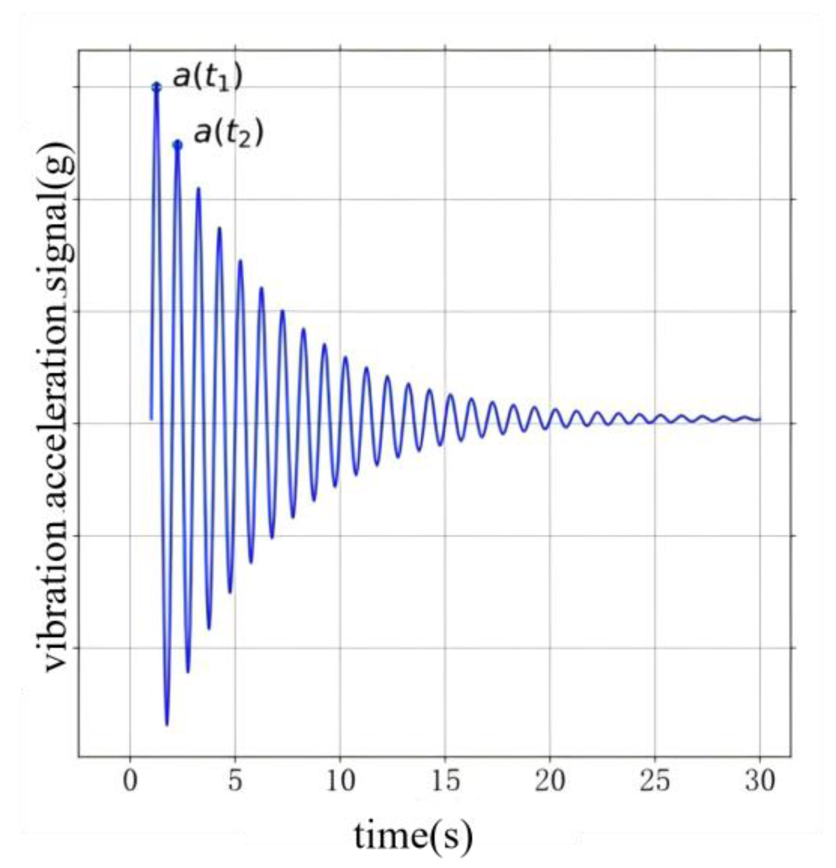
Figure 2.
Single-joint manipulator experimental device.
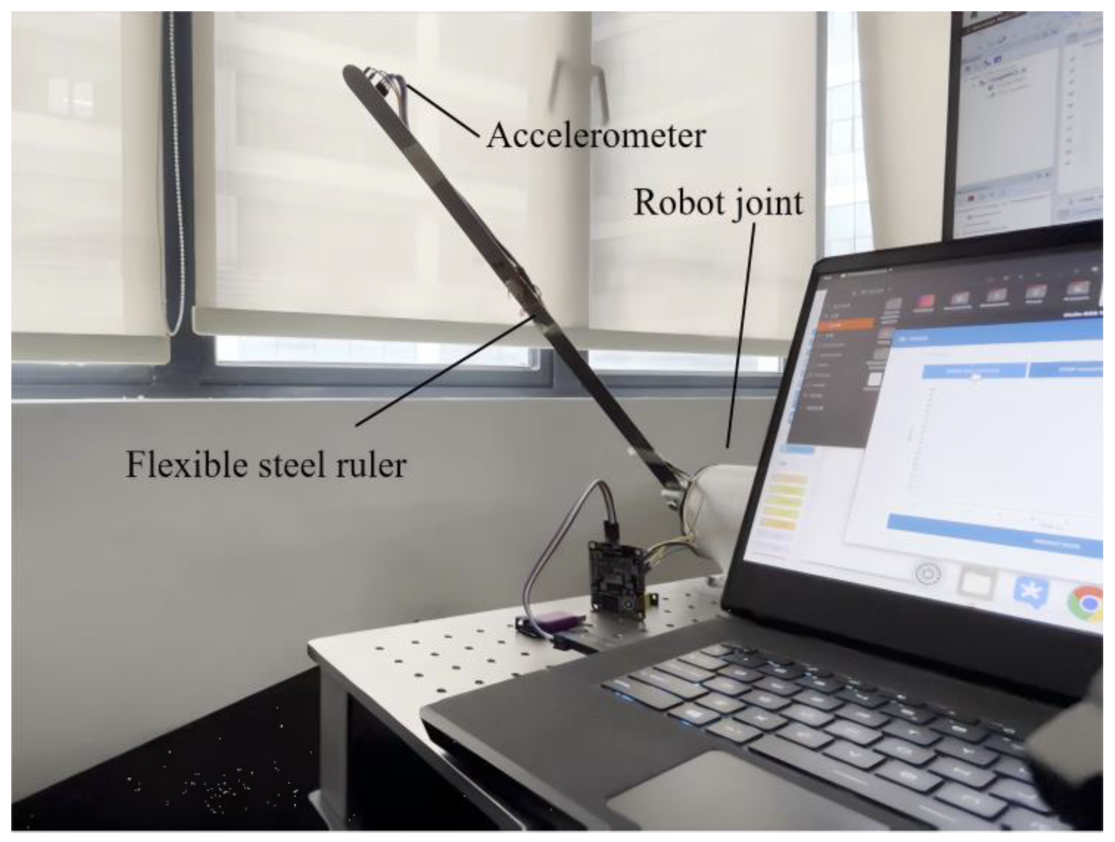
Figure 3.
Experimental results of input shaping for single-joint manipulator.
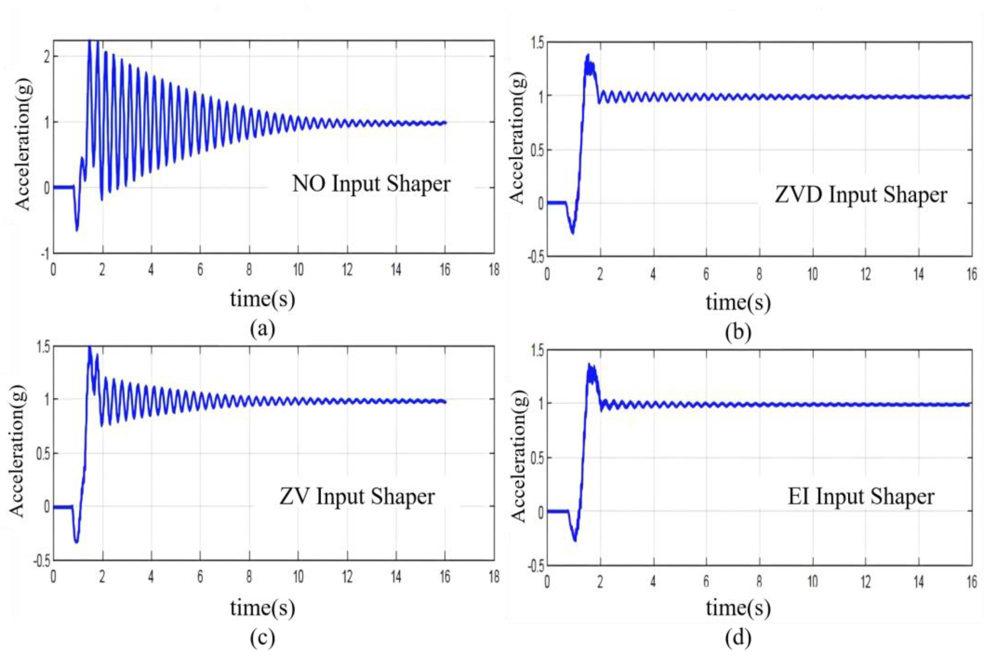
Figure 4.
16kg load collaborative robot experimental platform.
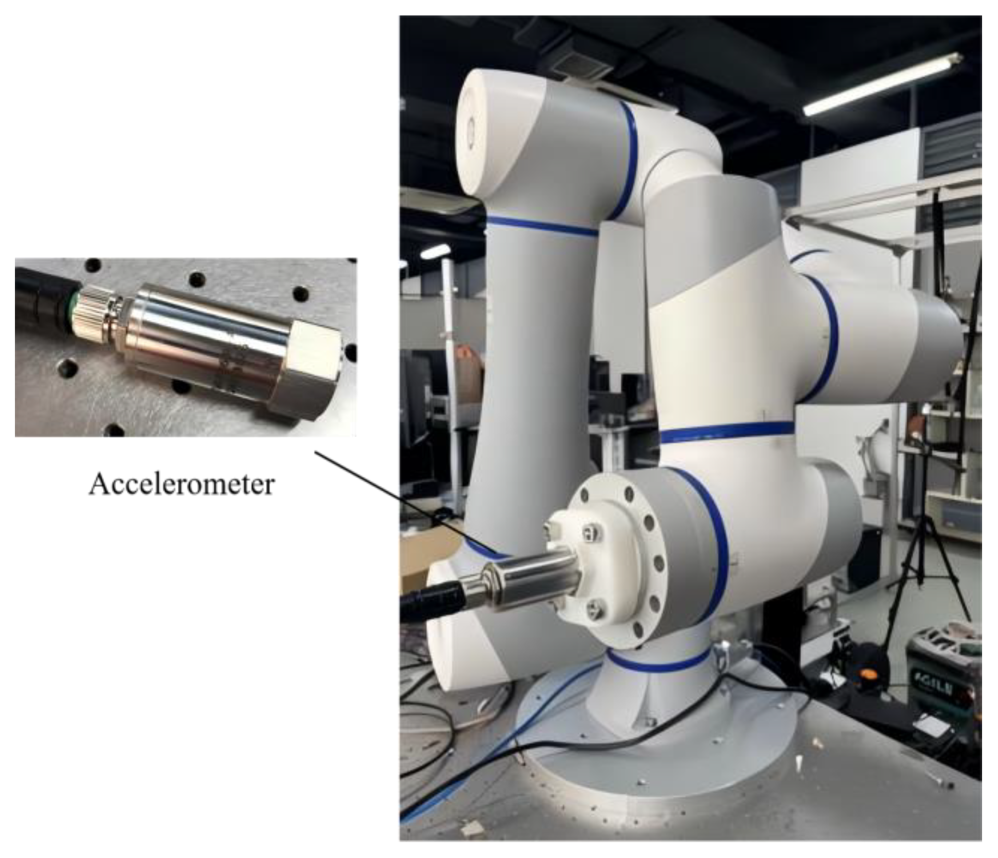
Figure 5.
Vibration parameter estimation for arbitrary poses.
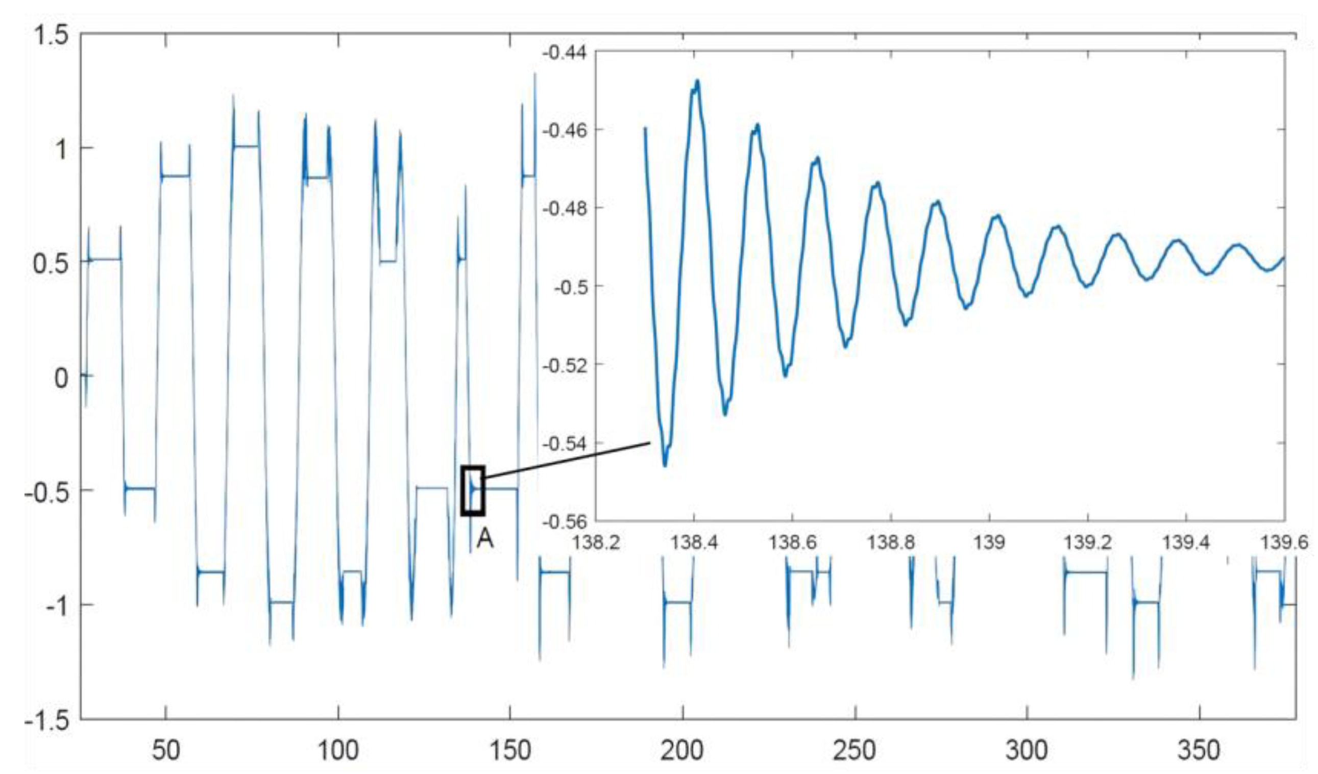
Figure 6.
Flowchart of Cartesian Space Design Method.
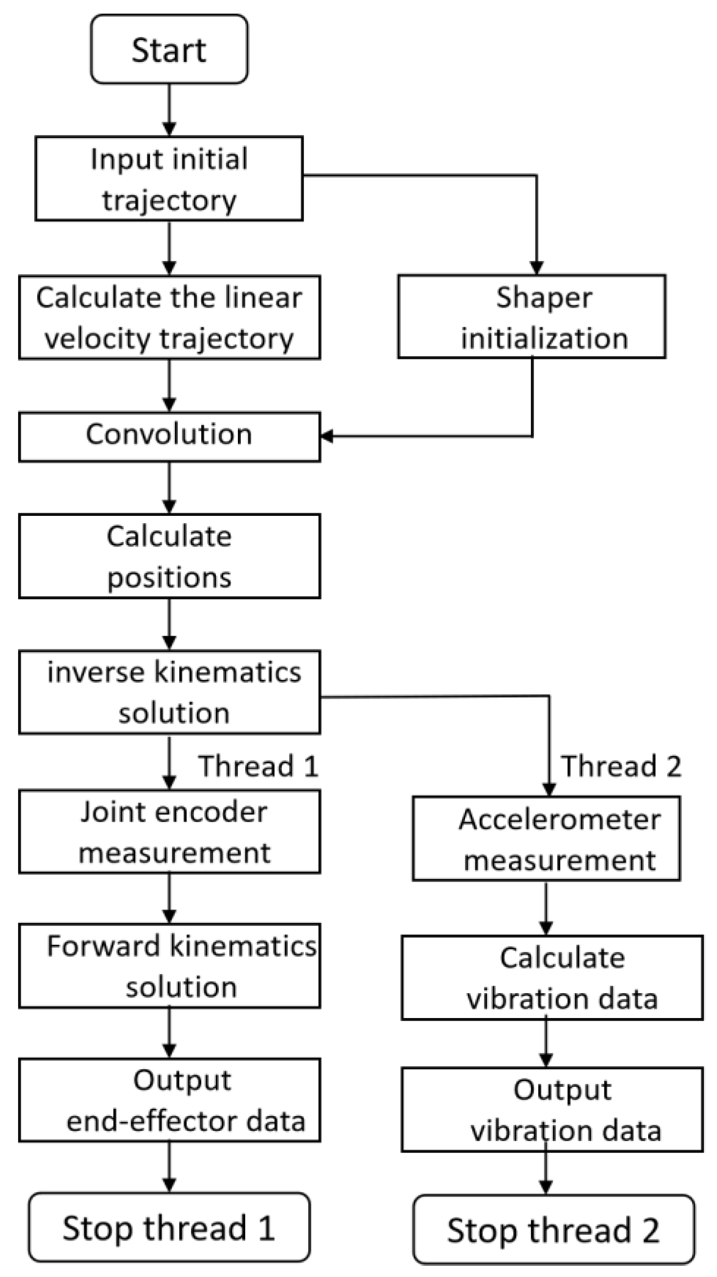
Figure 7.
The effects of input shaping on vibration suppression.
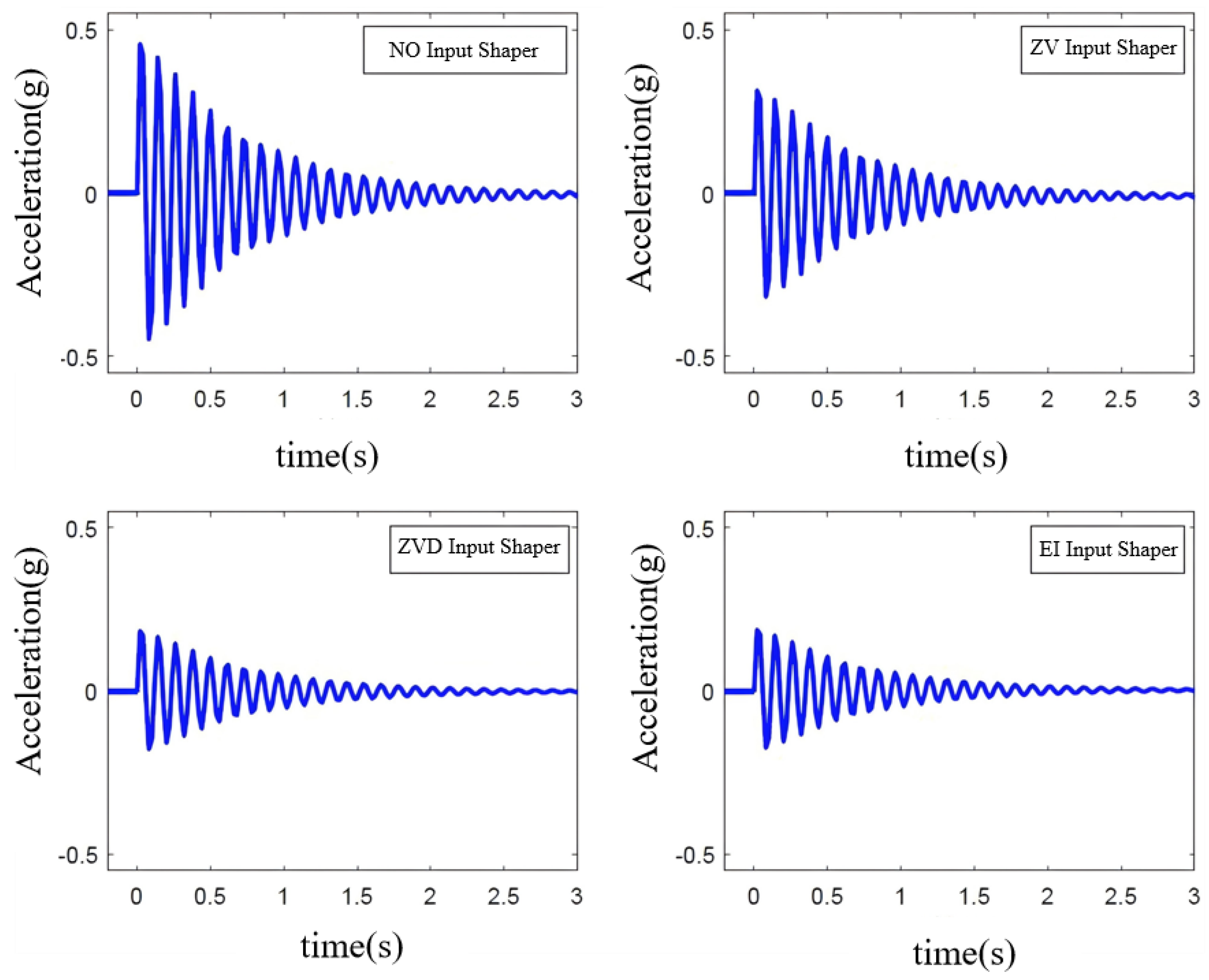
Table 2.
Parameters of the robot and accelerometer.
| Items | Joints | Parameters |
| Robot weight (kg) | / | 40 |
| Rated load (kg) | / | 16 |
| Working radius (mm) | 1000 | |
| Maximum operating speed(m/s) | 3 | |
| Joint range of motion (°) | J1 | ±360 |
| J2 | ±360 | |
| J3 | ±160 | |
| J4 | ±360 | |
| J5 | ±360 | |
| J6 | ±360 | |
| Maximum joint speed (°/s) | J1/J2 | 120 |
| J3/J4/J5/J6 | 180 | |
| Repeat positioning accuracy (mm) | / | ±0.03 |
| Power consumption (W) | / | 350 |
| The range of accelerometer (g) | / | ±16 |
| The resolution of accelerometer (mg/LSB) | / | 0.488 |
| The sampling frequency of accelerometer (kHz) | / | 26.667 |
Table 3.
Estimated values, measured values and errors of some points.
| m(kg) | ||||||||||
| 0 | 0 | 0 | 0 | 8 | 58.28 | 76.28 | 30.88 | 0.0089 | 0.0106 | 19.10 |
| 30 | 0 | 0 | 0 | 8 | 62.53 | 63.53 | 1.590 | 0.0091 | 0.0087 | 4.390 |
| 30 | 30 | 0 | 0 | 8 | 68.34 | 64.34 | 5.850 | 0.0089 | 0.0108 | 21.34 |
| 30 | 30 | 30 | 0 | 8 | 69.07 | 73.07 | 5.790 | 0.0091 | 0.0092 | 1.090 |
| 30 | 30 | 30 | 30 | 8 | 69.89 | 62.89 | 10.01 | 0.0094 | 0.0088 | 6.380 |
| 60 | 30 | 30 | 0 | 8 | 69.15 | 59.15 | 14.46 | 0.0099 | 0.0088 | 11.11 |
| 60 | 30 | 60 | 0 | 8 | 69.73 | 62.73 | 10.03 | 0.0100 | 0.0086 | 14.00 |
| 60 | 30 | 60 | 30 | 8 | 70.02 | 77.02 | 9.990 | 0.0087 | 0.0086 | 1.140 |
| 60 | 60 | 0 | 0 | 8 | 76.46 | 82.46 | 7.840 | 0.0092 | 0.0101 | 9.780 |
| 90 | 0 | 0 | 0 | 16 | 58.46 | 44.05 | 24.65 | 0.0099 | 0.0094 | 5.050 |
Table 4.
Vibration suppression effect of 6-DOF manipulator.
| Items | Maximum Amplitude() | Optimization Effect |
| NO Input Shaper | 0.4692 | / |
| ZV Input Shaper | 0.3155 | 32.8% |
| ZVD Input Shaper | 0.1849 | 60.6% |
| EI Input Shaper | 0.1825 | 61.1% |
Table 5.
Vibration suppression effect of some points.
| m(kg) | |||||||||
| 0 | 0 | 0 | 0 | 0 | 0 | 8 | 25.82 | 40.73 | 43.02 |
| 0 | 30 | 0 | 0 | 0 | 0 | 8 | 55.46 | 78.07 | 77.41 |
| 0 | 30 | 30 | 0 | 0 | 0 | 8 | 49.25 | 66.67 | 66.57 |
| 0 | 30 | 30 | 30 | 0 | 0 | 8 | 45.58 | 62.60 | 65.44 |
| 0 | 30 | 30 | 30 | 30 | 0 | 8 | 38.67 | 62.89 | 10.01 |
| 0 | 60 | 30 | 30 | 0 | 0 | 8 | 39.85 | 57.92 | 57.34 |
| 0 | 60 | 30 | 60 | 0 | 0 | 8 | 37.86 | 65.14 | 68.30 |
| 0 | 60 | 30 | 60 | 30 | 0 | 8 | 40.05 | 60.25 | 62.37 |
| 0 | 60 | 60 | 0 | 0 | 0 | 8 | 36.72 | 59.98 | 62.95 |
| 0 | 90 | 0 | 0 | 0 | 0 | 16 | 28.43 | 45.89 | 46.07 |
Disclaimer/Publisher’s Note: The statements, opinions and data contained in all publications are solely those of the individual author(s) and contributor(s) and not of MDPI and/or the editor(s). MDPI and/or the editor(s) disclaim responsibility for any injury to people or property resulting from any ideas, methods, instructions or products referred to in the content. |
© 2025 by the authors. Licensee MDPI, Basel, Switzerland. This article is an open access article distributed under the terms and conditions of the Creative Commons Attribution (CC BY) license (http://creativecommons.org/licenses/by/4.0/).
Copyright: This open access article is published under a Creative Commons CC BY 4.0 license, which permit the free download, distribution, and reuse, provided that the author and preprint are cited in any reuse.


