1. Introduction
Friction Stir Welding (FSW) is characterized by solid-state joining, low heat input, a low defect rate, and excellent mechanical properties. It has rapidly become a mainstream technology for joining aluminum alloys and dissimilar materials [
1,
2,
3]. In high-end manufacturing sectors such as aerospace [
4], rail transportation [
5], shipbuilding [
6], and automotive industries [
7], FSW has demonstrated broad applicability for large thin-walled panels, high-strength alloys, and multi-material joints [
8]. However, the increasing demand for lightweight, high-strength products in spacecraft, ships, and new energy vehicles has increased the complexity of welding curved or multidimensional structures. Traditional FSW machines, with limited degrees of freedom, often fail to achieve high-precision welding on three-dimensional curved workpieces over large spatial ranges [
9]. To meet the high-quality requirements of multi-angle, multi-curved, and large-scale workpieces, both academia and industry have begun integrating industrial robots with FSW. This approach, termed Robotic FSW (RFSW), offers enhanced flexibility and scalability, improving welding automation and adaptability to complex workpieces, thus providing new solutions for high-end equipment manufacturing [
10].
In RFSW systems, the core assembly includes the robot body, stirring spindle (comprising the electric spindle, stirring pin, and tool holder), and welding fixtures [
11,
12]. The robot body typically withstands axial pressures ranging from several thousand to tens of thousands of newtons, leading to the frequent selection of high-load serial or parallel/hybrid robots to meet stiffness requirements [
13,
14]. For example, ABB developed the IRB 7600 and ESAB Rosio series, capable of handling loads up to 500 kg, welding plates up to 7 mm thick, and integrating force-sensing capabilities [
15]. Additionally, parallel or hybrid robots such as the Neos Tricept and IRB 940 provide high stiffness and effective load capacities exceeding 1300 kg, enabling the welding of thick plates [
16,
17]. However, parallel robots face constraints in flexibility and reachable workspace. Similarly, FANUC integrated the CRIO spindle system with its M-900i series of serial robots to develop an intelligent RFSW production line, further refining load capacity and system integration with the M-900iB and KR500MT models [
18].KUKA employed its KR500 series serial robots for FSW tasks involving large flat panels and moderately curved components in the automotive and aerospace industries. Kolegain et al. improved welding accuracy for serial robots on three-dimensional seams through offline trajectory planning (using B-spline curves) and static deformation compensation [
19,
20]. Qin proposed a real-time error compensation method based on a nonlinear high-gain observer to address control challenges in six-axis industrial robots with joint flexibility in FSW and machining. This approach integrates dynamic modeling, stiffness identification, and robotic control simulation to enhance state estimation accuracy and positioning control, enabling high-precision welding and machining [
21]. Gao introduced a wireless multi-dimensional force sensing system for hybrid FSW robots, integrating an elastomer with eight pairs of strain gauges to achieve high-precision force measurement [
22]. This system expands the measurement range, reduces cross-talk, and improves the controllability and stability of the welding process. Overall, multi-degree-of-freedom industrial robots in RFSW offer high flexibility and a broad working range. However, end-effector stiffness and joint flexibility remain key limitations in high-load solid-state welding.
In robotic FSW, offline compensation is widely adopted to reduce deformation and positioning deviations. A stiffness and thermo-mechanical coupling model of the robotic system is typically established to estimate joint forces and thermal deformations, facilitating reverse compensation in seam trajectory planning and improving welding precision [
23]. For example, Beijing Sifoster company employed pre-weld spatial trajectory simulations to mitigate flexibility-induced errors in weld formation [
24]. Xiao et al. proposed a constant plunge depth control method based on online trajectory generation, incorporating real-time pose measurement, deformation compensation modeling, and dynamic trajectory optimization to reduce vibration and welding defects, thereby improving weld quality in RFSW [
25]. Kolegain et al. introduced a feed-forward compensation technique, integrated with offline path planning using Bézier curves, to minimize end-effector deviations in RFSW and achieve high positional and orientational accuracy despite the limited stiffness of serial robots [
26]. Mario et al. applied real-time lateral deviation compensation using an embedded elastostatic model and real-time path correction, mitigating lateral tool deviation during welding. However, offline models often exhibit insufficient predictive accuracy when confronted with uncertain curved workpieces, real-time thermal softening, or material fluctuations. They also cannot adapt if deviations occur during the welding process.
To improve real-time adaptability, force/position sensors and advanced control algorithms are increasingly integrated into robotic FSW to establish online closed-loop regulation [
27]. A common approach is constant pressure control, wherein force sensors measure the axial load on the stirring head while a PID-based algorithm adjusts the Z-axis position. This method ensures that the downward force remains near the target value [
28]. For instance, Mendes et al. combined force control with motion control to maintain suitable welding forces, thereby ensuring sufficient plastic flow [
29]. Longhurst et al. examined how welding speed, rotational speed, and axial force affect weld quality, determining that pressure control significantly improves seam consistency in automated FSW systems [
30,
31]. However, thermal softening may cause a continuous buildup of downward force, leading to edge spattering or end deformation. Another method is constant displacement control, which employs high-precision distance or displacement sensors (e.g., laser displacement sensors or LVDTs) to monitor the stirring head’s insertion depth. Dynamic adjustments are then performed to maintain a stable welding depth [
32]. Although this approach stabilizes weld-seam dimensions, it remains sensitive to fluctuations in frictional heat resulting from uneven material temperatures. As a result, “hard” or “soft” zones with non-uniform properties may appear in the weld.
To overcome the limitations of constant pressure and constant displacement control, force/position hybrid control has been studied. This strategy uses closed-loop control to regulate both the downward force and the stirring head’s relative position, thereby balancing plastic flow and geometric uniformity in the weld seam. Kamm et al. proposed a force control method for robotic friction stir welding (RFSW) based on an open control architecture, comparing admittance control, parallel force control, and conventional external force control [
33]. Raibert originally introduced force/position hybrid control in robotic arm operations, and Smith et al. later applied it to FSW, demonstrating that hybrid control significantly reduces weld defects compared to pure position control [
34]. Fehrenbacher et al. embedded thermo-couples in the tool to integrate temperature sensing with force sensing, thus coordinating thermal and force parameters [
35].
Overall, force/position hybrid control is regarded as a key direction for robotic FSW but still requires more comprehensive hardware/software integration and greater adaptability to complex curved-surface welding scenarios.
In light of these challenges, a robotic FSW system based on force/position hybrid control is proposed in this study to achieve high-precision welding of large-scale curved structures. An integrated robotic FSW setup is presented, and the coupling mechanisms between robotic joint deformation and weld seam plastic flow under high loads are analyzed. A force/position hybrid control strategy incorporating real-time weld-seam monitoring is introduced and validated, allowing synchronized adjustment of both welding depth and downward force. Experimental validation on planar and spatially curved surfaces is then conducted to assess the effectiveness of this strategy in enhancing welding precision, quality, and automation. This study thus provides new theoretical insights and technological solutions for complex curved-structure welding and expands the application of industrial robots in high-load, multi-degree-of-freedom tasks.
2. Design of the Robot Friction Stir Welding System
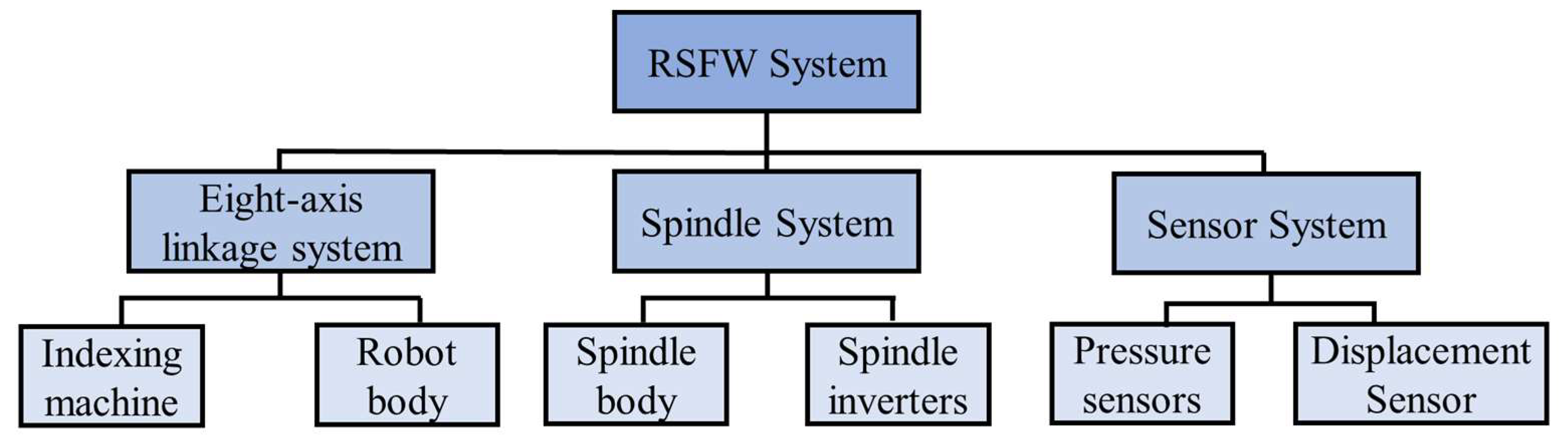
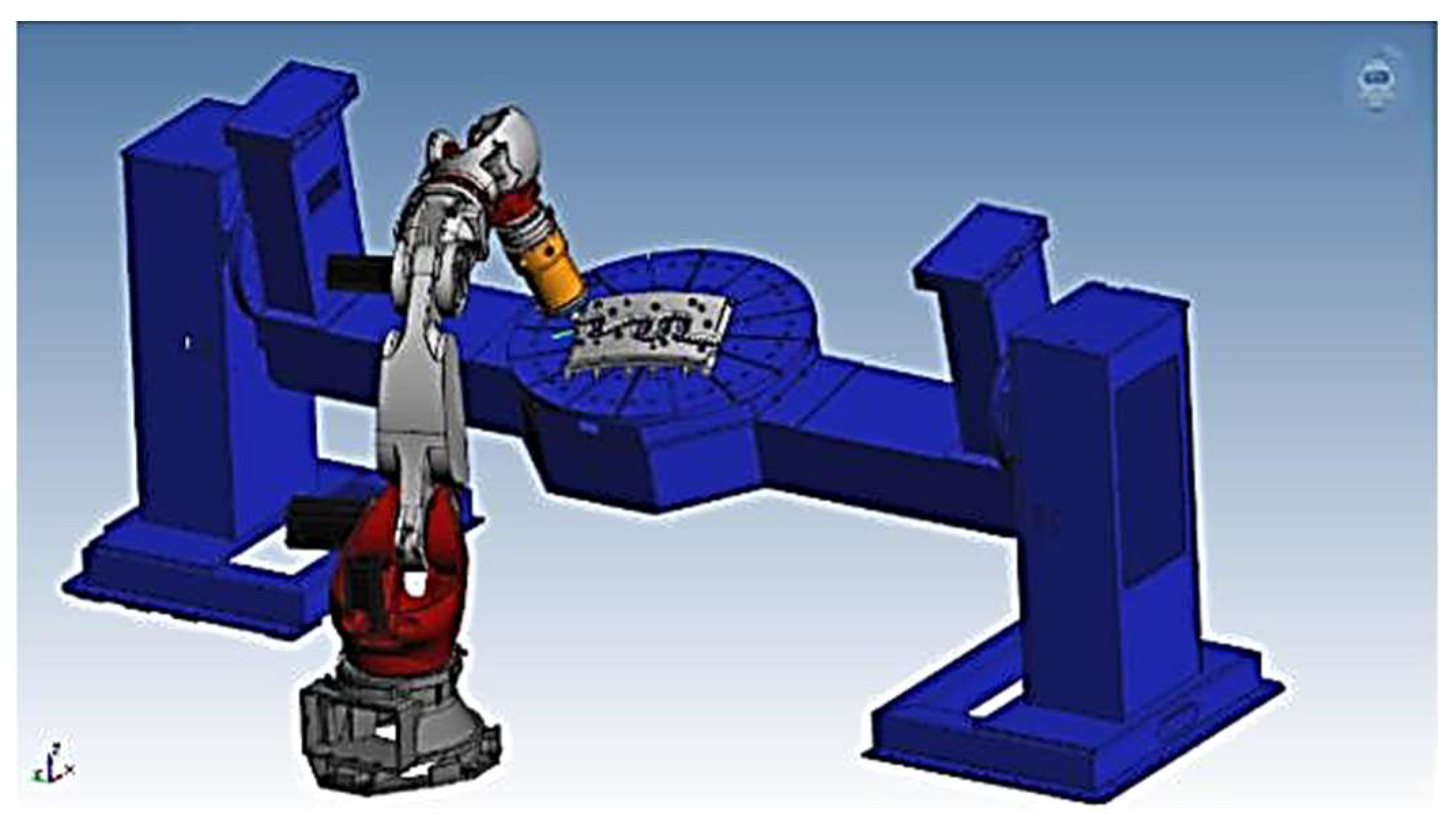
The robot friction stir welding system is designed to meet the needs of high-precision welding tasks through an integrated control system. As shown in
Figure 1, the system consists of several key components: the eight-axis linkage subsystem, spindle system, sensor system, and control system. At the core of the system lies the eight-axis linkage system, which integrates a six-degree-of-freedom robot body with two positioners. This combination enhances the operational range and flexibility, enabling the robot to follow complex welding trajectories. The spindle system, integrated with the robot’s control system, ensures precise energy input and control during welding, using an electric spindle and frequency converter. Meanwhile, the sensor system monitors real-time data, such as force and depth, using force sensors and laser distance sensors, providing continuous feedback for force-position control, which is crucial for maintaining weld quality and process stability.
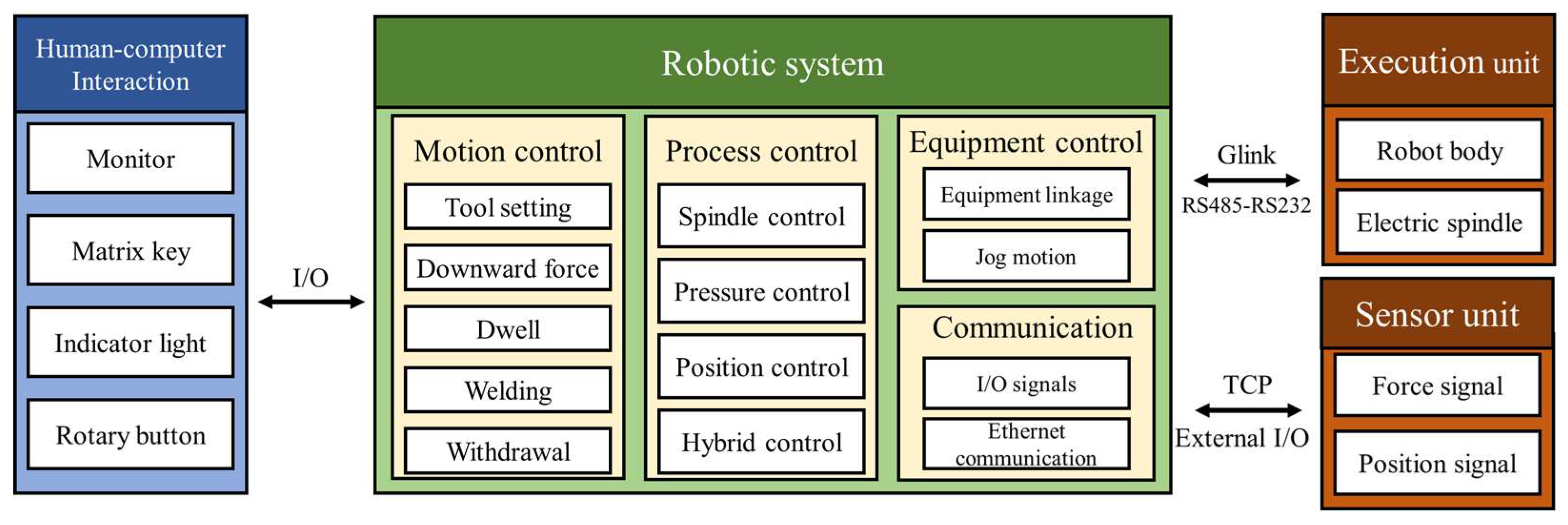
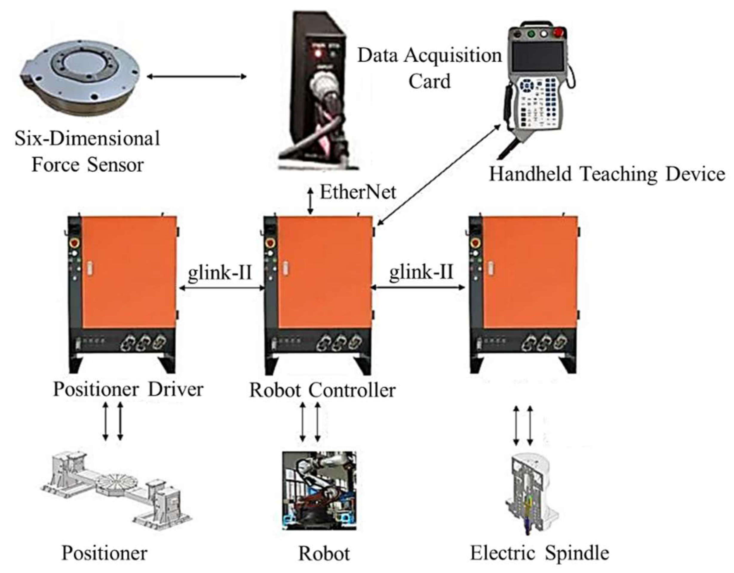
The robot friction stir welding control system is divided into four major modules: the human-machine interaction module, robot system layer, execution unit, and sensor unit. The human-machine interaction module facilitates the exchange of information with the system through I/O interfaces, displaying welding process parameters and real-time data feedback. This ensures the operator can monitor and adjust the process in a timely manner. As shown in
Figure 2, the robot system layer serves as the control core, handling motion control, process control, external communication, and emergency stop functions. The GOGO R688 controller used in this system supports multi-axis synchronous control and various data transmission protocols like ModBus TCP, enabling real-time robot trajectory calculations and the transmission of data to the application layer.
The execution unit includes the robot body, positioners, and electric spindle, all working in coordination to perform the welding tasks. These components ensure spatial positioning and energy output. The sensor unit consists of a six-dimensional force sensor and a laser sensor, both of which collect mechanical and positional signals during the welding process. These signals are crucial for supporting the force-position hybrid control system.
In addition, the system’s design is open and modular, allowing for flexibility and adjustments based on the specific needs of the task. It provides real-time monitoring and the ability to adjust parameters like constant pressure control, constant displacement control, and spindle control through integrated plug-ins. The GTRobot control platform, which is open and reconfigurable, serves as the system’s backbone, enabling the integration of external devices. This open system not only controls the electric spindle, including settings for speed, start/stop, and direction, but also facilitates force-position control, a key component of the system’s success. The sensor unit ensures precision by transmitting real-time mechanical and positional data to the control system, supporting the accuracy of the welding process. Additionally, the RSI correction function enables dynamic, real-time adjustments to the force-position control system, ensuring stability and precision during welding.
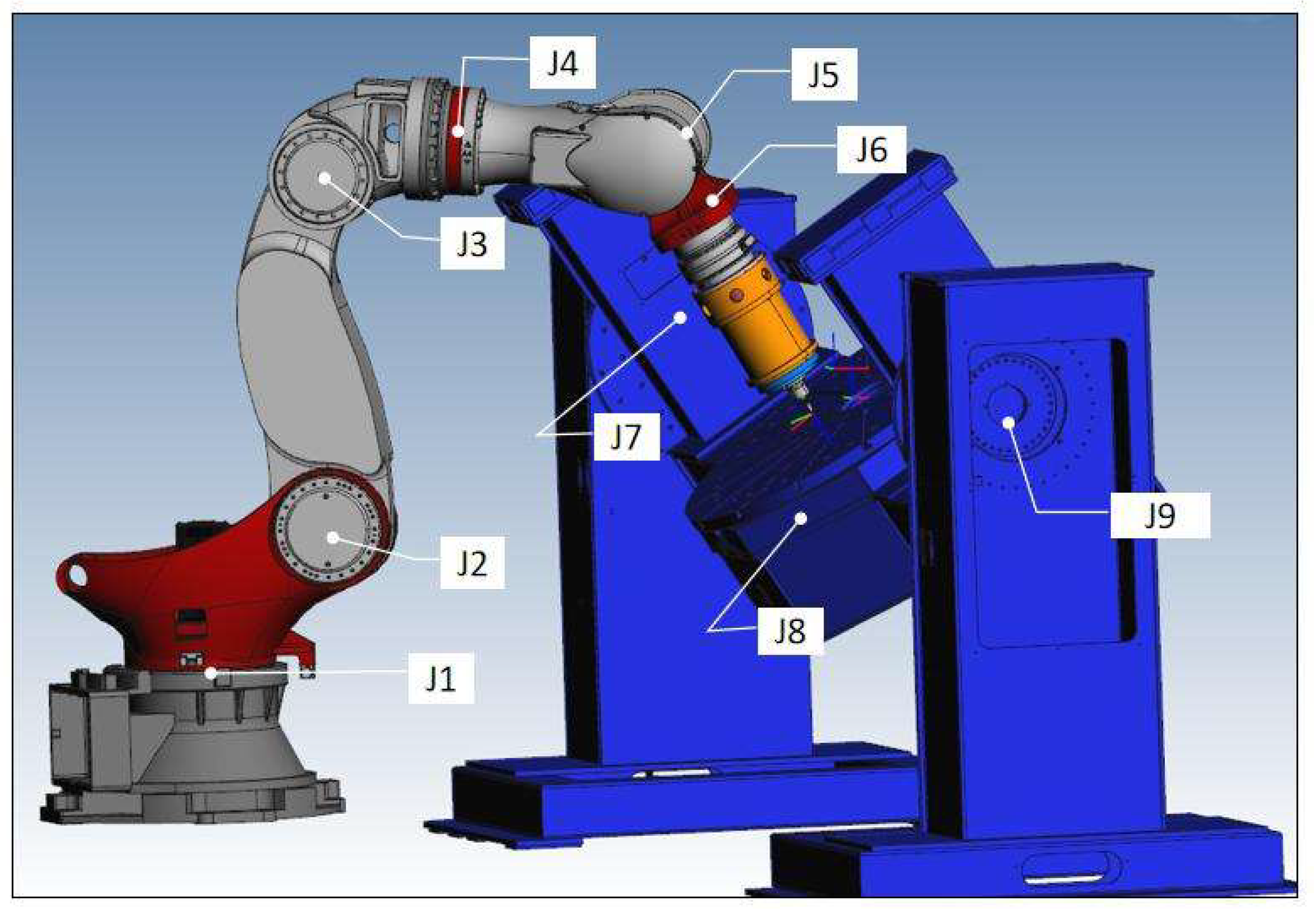
The design of the eight-axis linkage system is essential for accommodating complex welding trajectories and dynamic operational environments. This system incorporates a six-degree-of-freedom robot and two positioners, which are crucial for ensuring precise control of the weld seam during welding.
Figure 3 illustrates the offline model of the eight-axis linkage system, which shows how the robot and positioners are configured to achieve high-precision, high-dynamic response welding by controlling the joints precisely.
The hardware components of the eight-axis linkage system include the robot body, positioners, the Gotech R688 controller, and servo drivers. The controller supports multi-axis synchronization and real-time communication via the gLink bus protocol. This integration of components ensures that the system maintains flexibility and precision during the welding process, extending the robot’s degrees of freedom and optimizing its operational capabilities.
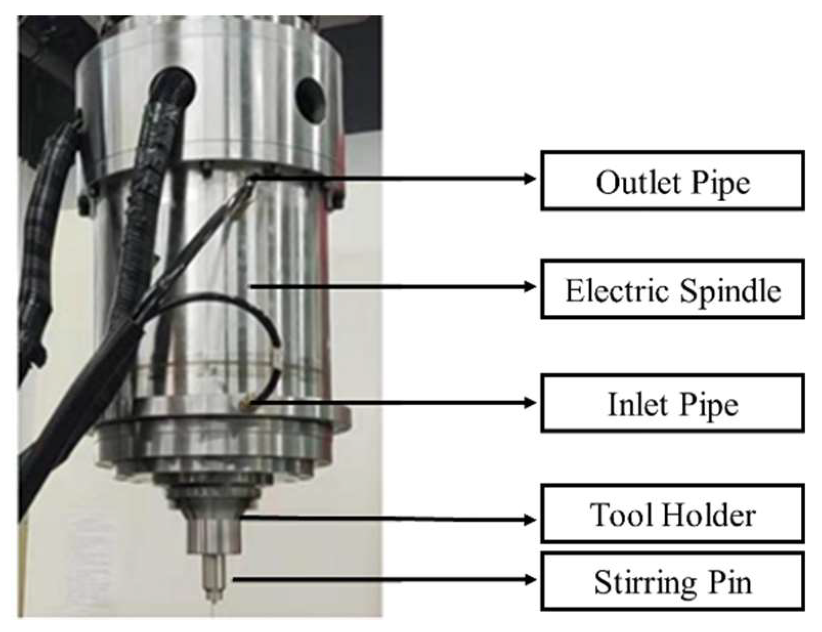
The spindle system in this design is integrated into the robot’s control system, unlike traditional systems where the spindle is controlled separately. This integration simplifies the system and enhances the response speed and stability, as shown in
Figure 4. The spindle’s integration with a frequency converter ensures precise control of speed and torque, while the water-cooling system prevents overheating, ensuring stable performance during extended welding sessions. The electric spindle has key parameters of the electric spindle are shown in
Table 1 below:
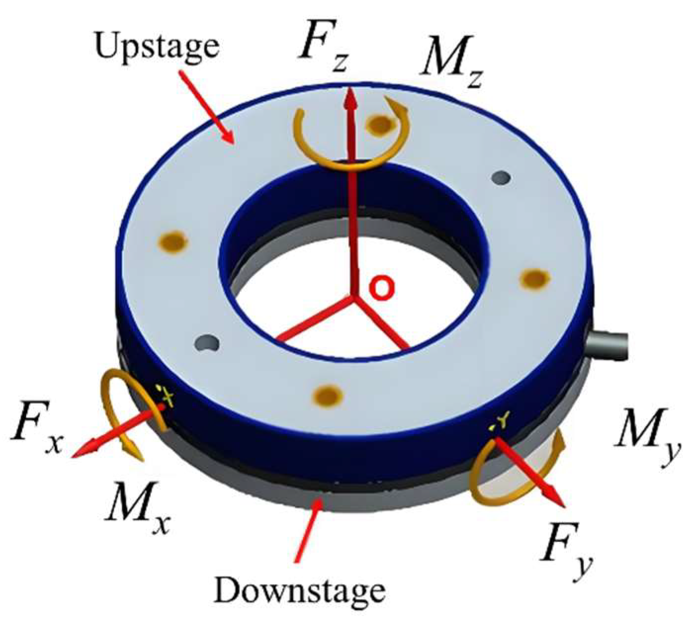
The sensor system plays an essential role in monitoring key parameters during welding, including welding depth, pressure, and temperature. The six-dimensional force sensor accurately captures forces and torques in all directions, particularly in the critical Fz direction, where the maximum load occurs. The range of this sensor extends from 0 to 15 kN, with a maximum load capacity of 30 kN. Calibration of the force sensor and electric spindle reduces axial pressure errors, measuring forces like gravitational force (
FG), mechanical installation force (
F1), and static force (
FD), resulting in the actual axial force (
Fs = FD + F1 − FG).
Figure 5 shows the schematic diagram of the six-dimensional force sensor structure and signal collection. This sensor’s precision is crucial for ensuring accurate force-position control during the welding process.
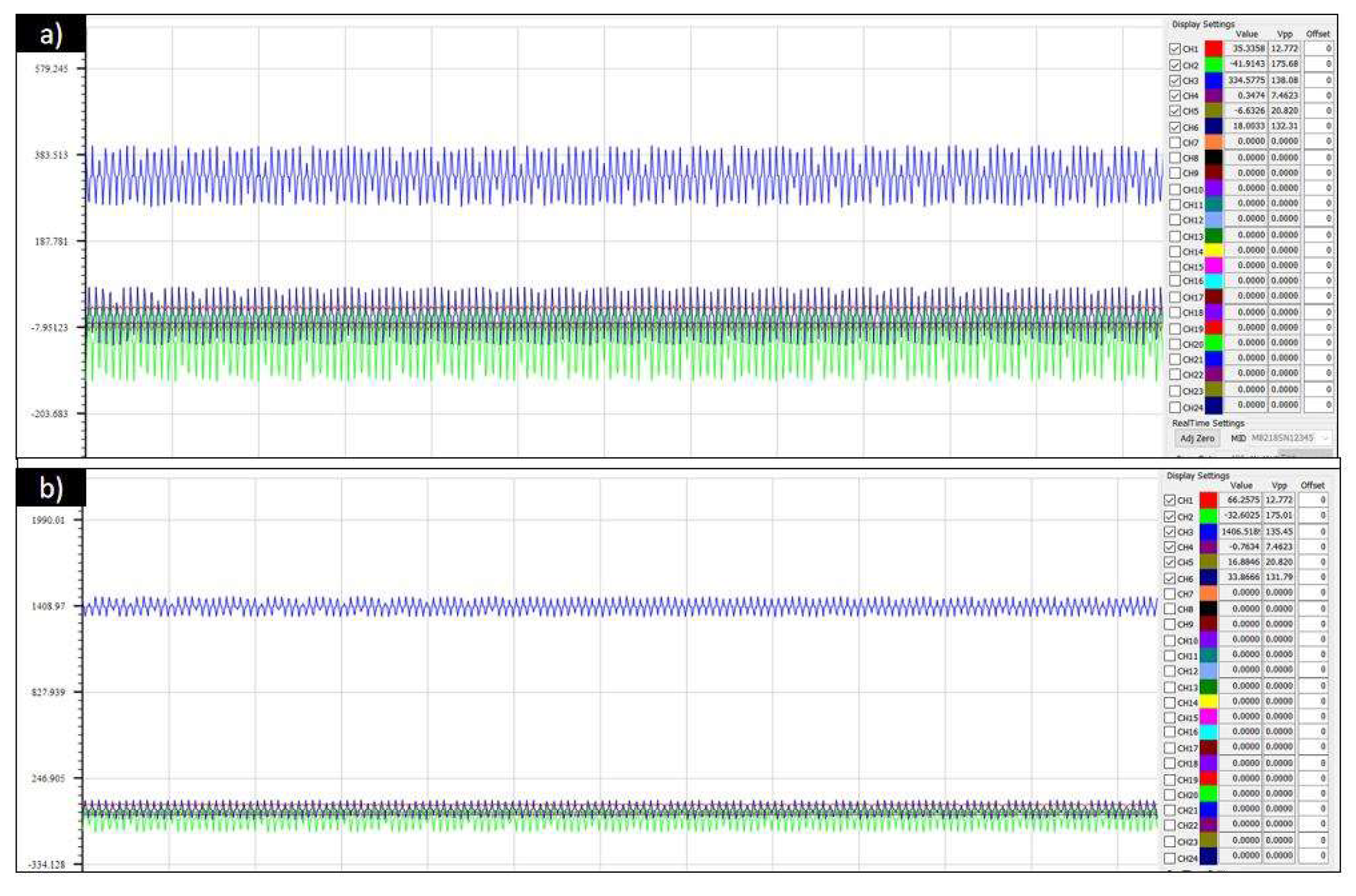
The data from the force sensor is presented in
Figure 6, which shows a calibration test where the measured axial force increases as additional components are connected. The measured force values of 327 N and 1406 N confirm the accurate calibration of the system, including the gravitational force of 1079 N.
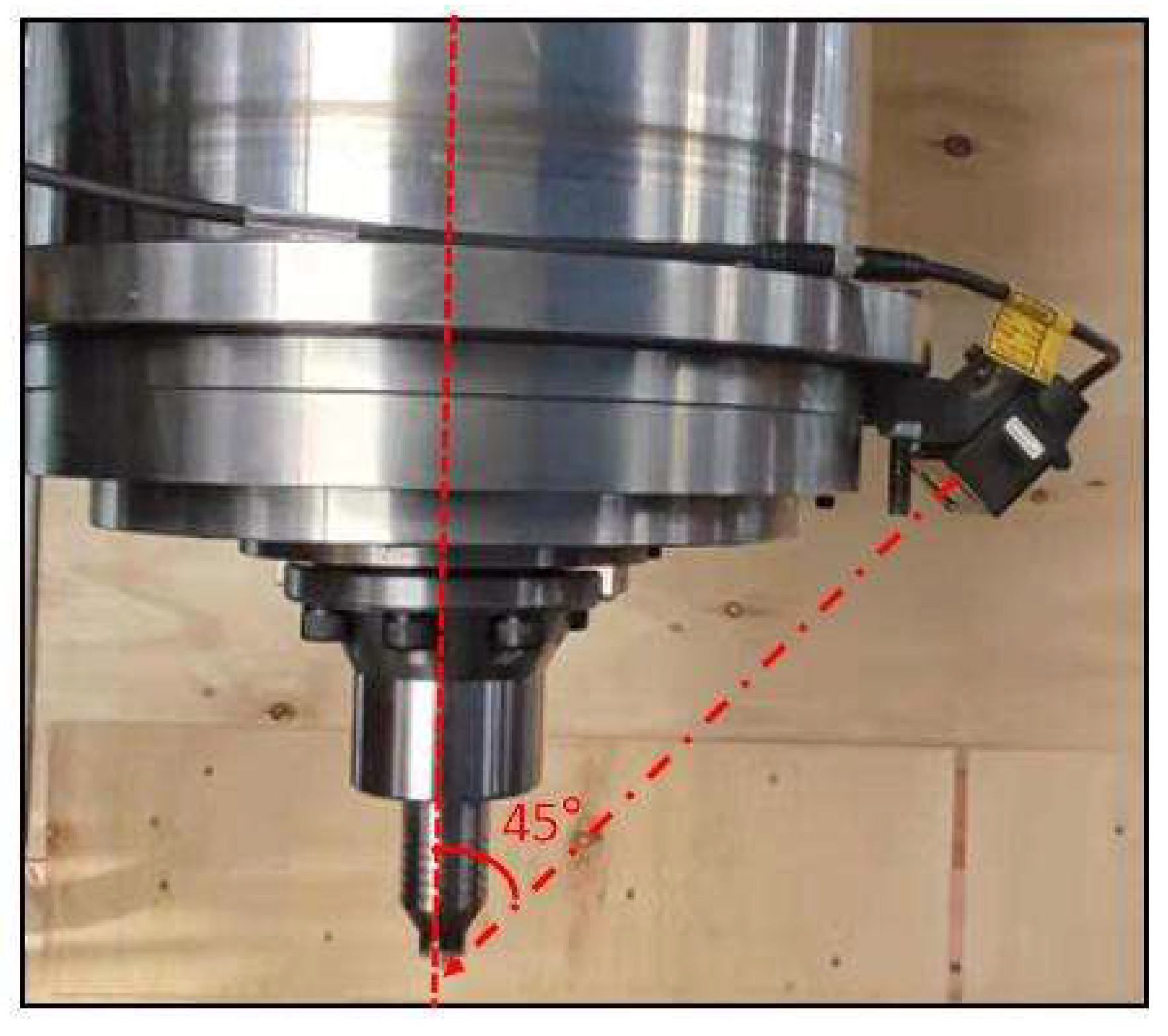
Additionally, the laser distance sensor plays a critical role in monitoring the welding depth, with a measurement range of 160 mm to 450 mm. As shown in
Figure 7, the sensor’s installation method is optimized by using an inclined angle, reducing measurement errors and improving accuracy.
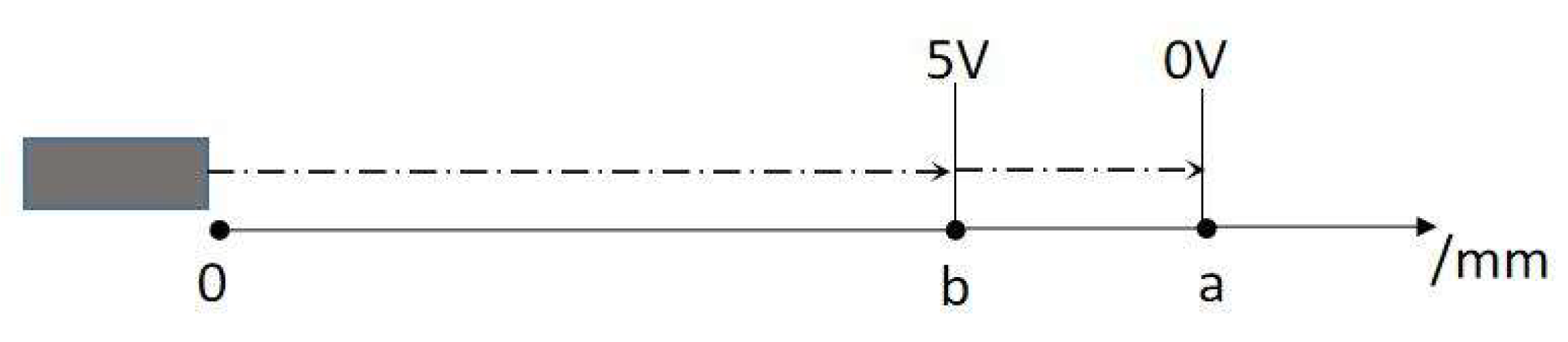
The sensor works by converting positional signals into voltage signals, which are then calibrated.
Figure 8 shows the calibration model of the laser sensor, where the sensor’s voltage output changes linearly with depth, ensuring high precision in depth control.
Figure 9 further illustrates the design of the laser sensor calibration process, confirming the sensor’s ability to provide real-time adjustments during the welding process.
3. Force/Position Control Strategy for Robotic Friction Stir Welding
During the welding process, the robot is prone to flexible deformation due to the forging forces, which leads to positional deviations and affects the weld quality. To address this issue, force/position control strategies are employed to compensate for these deviations, ensuring precision and stability in the welding process. Accurate force/position detection is crucial for online control. Multi-dimensional force sensors (such as piezoelectric quartz sensors or strain-based sensors) can be installed on the workbench or at the spindle’s front end. Alternatively, the robot’s internal bus (RSI) combined with the EtherCAT protocol can be used to acquire external force sensing data, enabling closed-loop regulation at millisecond cycles. For curved surface welding, laser displacement or vision sensors are often employed to detect downward pressure, lateral deviation, and workpiece surface posture, facilitating dynamic trajectory correction. However, the simultaneous demands of high load, multi-degree-of-freedom motion, and real-time high-speed data acquisition pose challenges in terms of integration and control software development.
3.1. Robotic Dynamic Offset Function and Position Correction Schemes
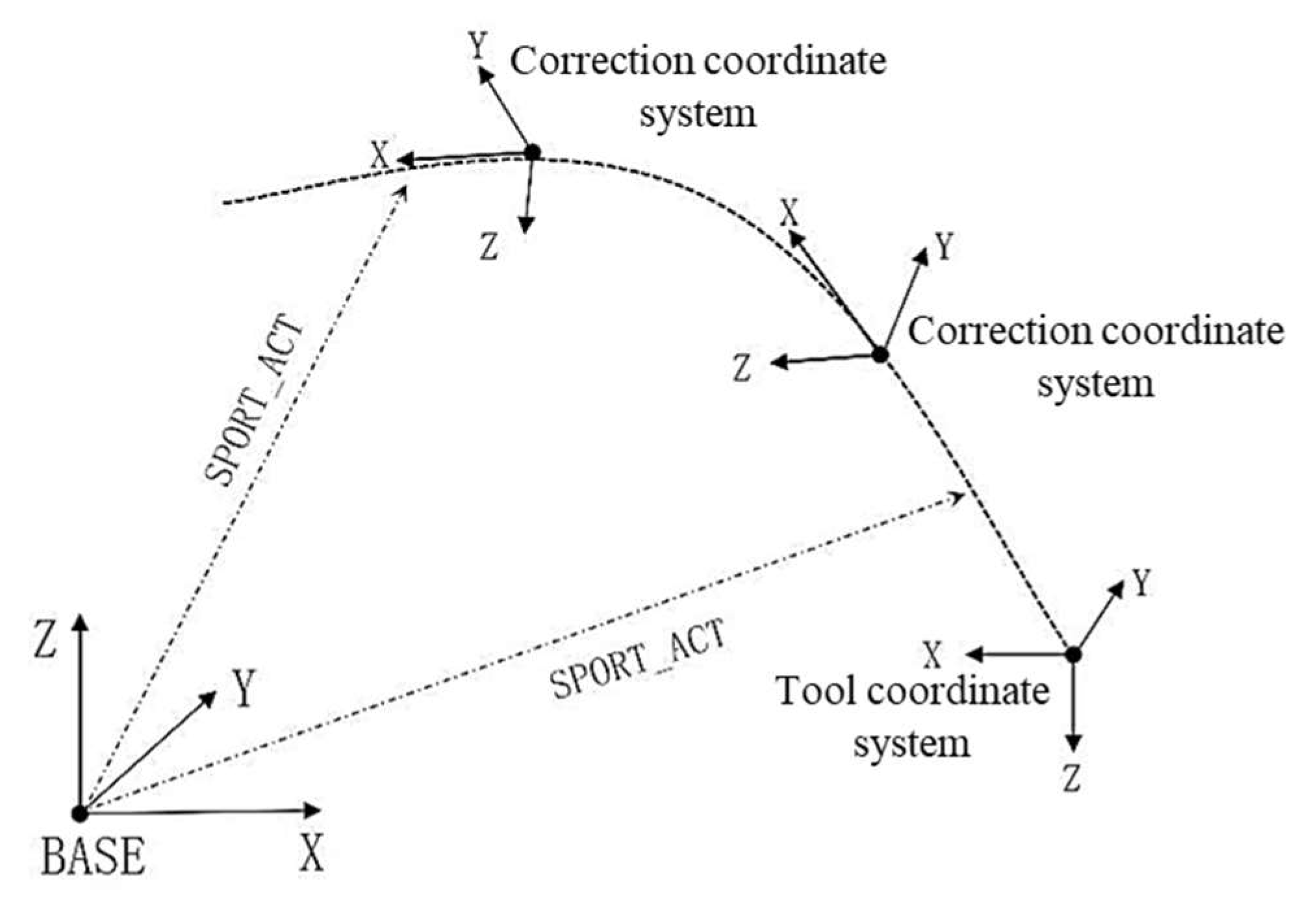
During the welding process, the robot’s stirring head contacts the workpiece, which causes flexible deformation of the robot’s arm due to the forging force. This deformation leads to positional deviations, causing the robot’s trajectory to shift. To resolve this, the dynamic offset function is integrated into the robot’s control system. This function allows for real-time spatial position correction based on a dynamic coordinate system. The core concept of dynamic offset is the real-time adjustment of the robot’s motion trajectory using a dynamic coordinate system, as shown in
Figure 10.
The Tool Coordinate System (TTS) is an extension of the robot’s base coordinate system, calculated using the joint matrix, with its origin located at the tool’s end center and the Z-axis perpendicular to the work surface. The Process Coordinate System (CCS), on the other hand, references the robot’s forward direction and is synchronized with the welding trajectory to ensure accuracy during position correction.
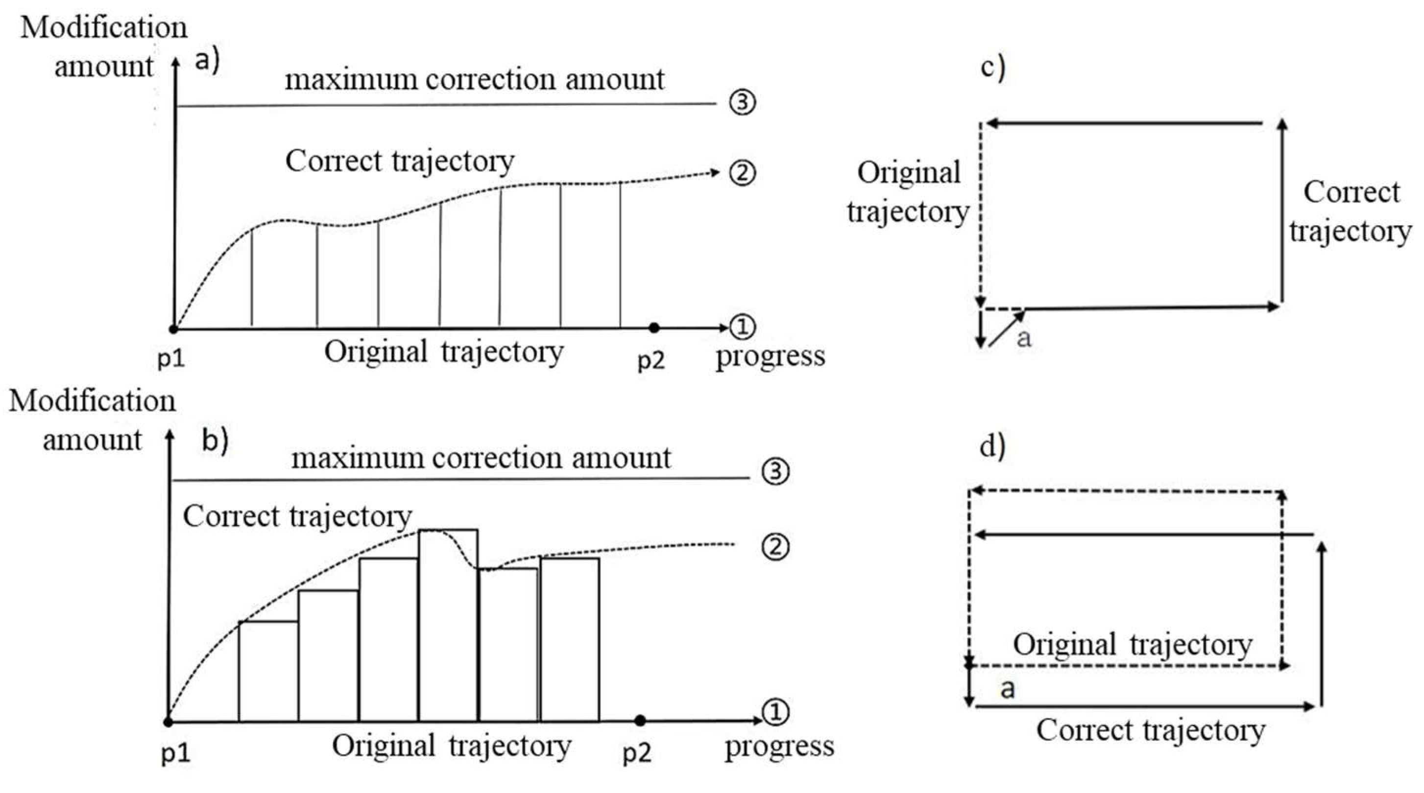
To ensure effective position correction during the welding process, this study proposes a dynamic offset correction scheme based on the Process Coordinate System (CCS). This scheme adjusts the position based on directional changes in robot movement during welding, as shown in
Figure 11. It is divided into two modes: the trajectory discontinuous correction scheme and the trajectory continuous correction scheme.
(1)Trajectory Discontinuous Correction Scheme: The correction applied to the previous segment of the trajectory will be ignored in the subsequent trajectory, and the later trajectory will be executed according to the taught point coordinates.
(2)Trajectory Continuous Correction Scheme: During the execution of multiple trajectory segments, the correction applied to the previous segment will be carried over to the subsequent trajectory, resulting in a cumulative offset.
Friction stir welding involves a strong bilateral physical connection, and discontinuous welding trajectories can cause significant system oscillations, leading to weld defects. In the initial design phase, two schemes were tested. In the first scheme, after the robot corrected the trajectory at the front end and switched direction, positional jumps occurred, causing system vibrations. The current in the motor driver surged, triggering a danger warning and an emergency stop. In contrast, the second scheme demonstrated smooth multi-segment trajectory execution with system stability. The final coordinates at the endpoint were the sum of the original interpolation point coordinates and the offset. Based on a comprehensive analysis, the second scheme with continuous multi-segment trajectory offset was determined to be optimal, while the first scheme was discarded
3.2. Research on Constant Displacement Welding Control Strategy and Constant Pressure Welding Control Strategy
The core objective of the constant displacement control strategy is to maintain a constant plunge depth of the stirring tool during welding, ensuring the stability of the welding process. During friction stir welding, the robotic arm is prone to flexible deformation, causing variations in the plunge depth of the stirring tool, which directly impacts the quality of the weld seam. Studies have shown that maintaining a constant axial shoulder plunge depth is crucial for ensuring welding quality. Therefore, the constant displacement control strategy is employed to achieve this goal.
Based on the robot’s DH model, constant displacement control is achieved through two approaches: the base coordinate origin offset scheme and the tool coordinate system offset scheme. The base coordinate origin offset scheme controls the robot’s end position by dynamically adjusting the origin of the base coordinate system, while the tool coordinate system offset scheme directly controls the plunge depth by adjusting the position of the tool center point (TCP).
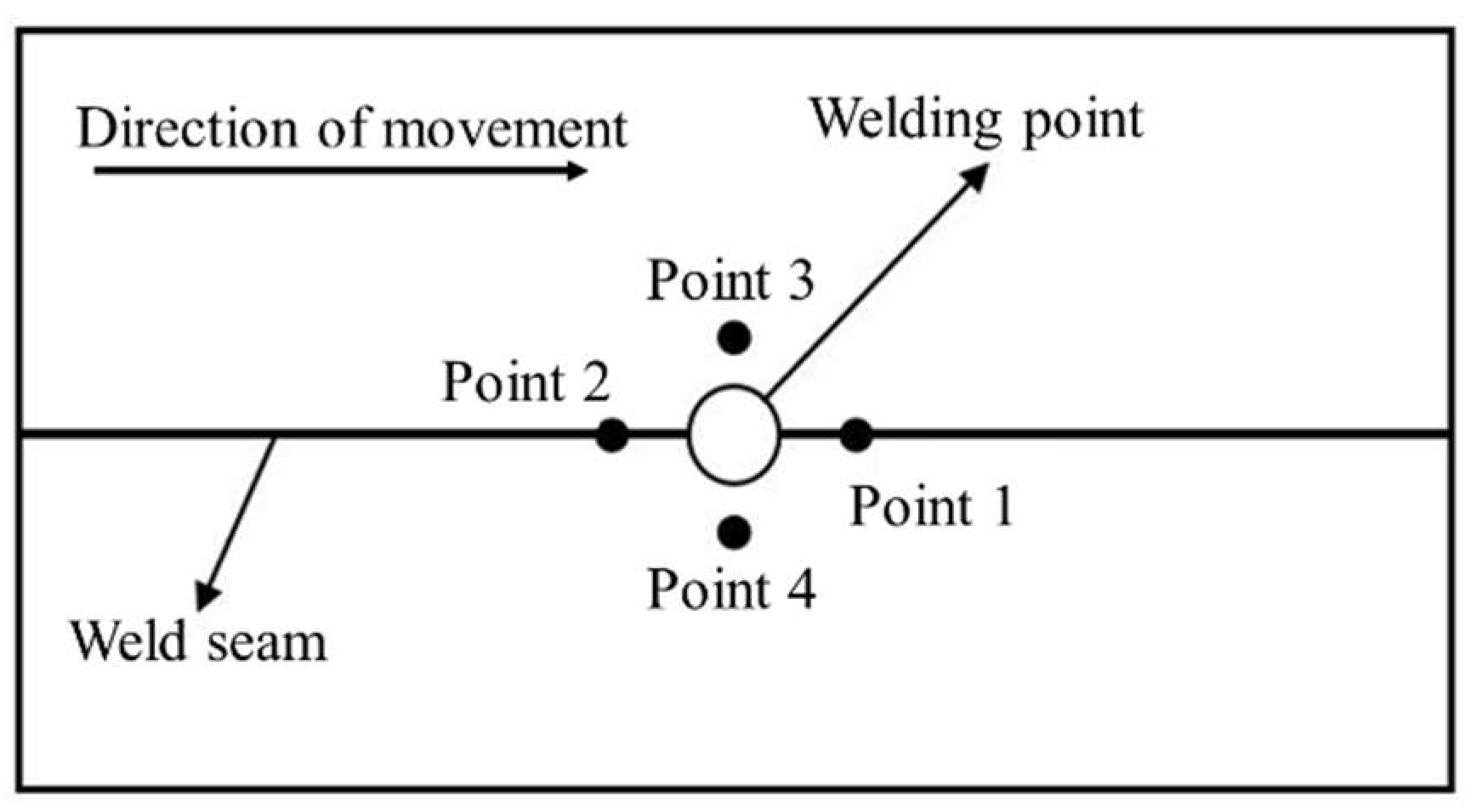
Figure 12 illustrates the analysis of the robot’s end position and the selection of position acquisition points, ensuring measurement accuracy and real-time performance. Points 1, 2, 3, and 4 represent the laser irradiation points located on the front, rear, left, and right sides, respectively, in the direction of advance. Based on the welding process theory, point 2, located at the rear side of the weld point, irradiates the already-welded seam. This often results in a concave surface, which is inconsistent with the height of the un-welded seam and is not suitable for reference. Point 3, on the left side of the weld point, causes spatter accumulation and burr formation when the spindle rotates counterclockwise. Conversely, point 4, located on the right side when the spindle rotates clockwise, experiences similar issues. Both points 3 and 4 lead to inaccurate position feedback due to spatter interference. In contrast, point 1, avoiding these issues, accurately represents the weld seam information and provides forward feedback, thus meeting the requirements for constant displacement control. Therefore, point 1 is selected as the reference for data collection. Effective position deviation correction is achieved through the collaboration of a laser sensor and position signal controller.
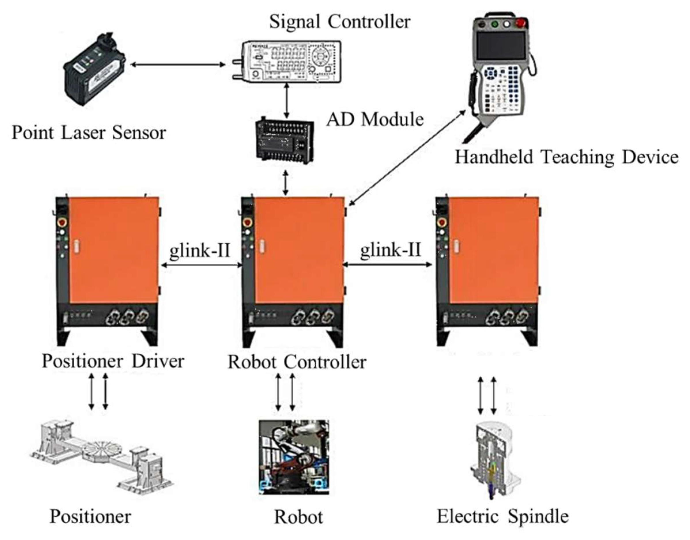
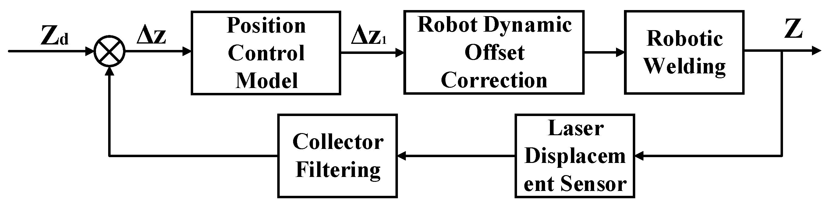
Based on the above control strategy, a constant displacement control system is designed, with the hardware structure shown in
Figure 13. The system consists of key components such as a laser sensor, robot controller, positioner, and electric spindle. Dynamic offset control is achieved through feedback of position signals via a signal controller.
In the constant displacement control system, the robot’s end effector displacement is controlled using a combination of a PI controller and a Dirichlet integral model. The Dirichlet integral model is used for displacement adjustment over a large range, while the PI controller is employed for finer control within a smaller range. The control model, shown in
Figure 14, ensures the stability and efficiency of the welding process.
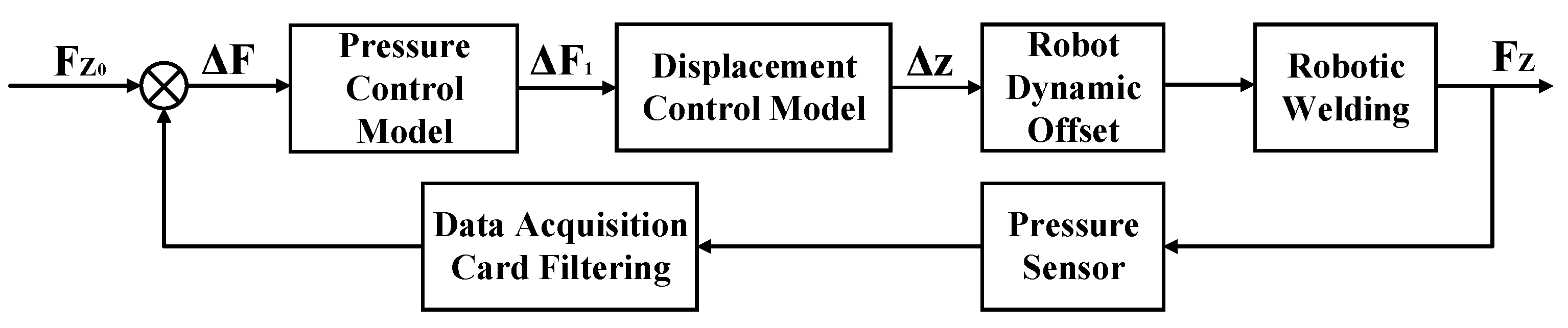
The constant pressure control strategy plays a crucial role in robotic friction stir welding, especially when variations in the axial forging force affect welding quality. Constant pressure control ensures the mechanical properties and quality of the weld seam by regulating the axial pressure. In constant pressure control, force feedback-based impedance control is widely used. This approach uses force sensors to monitor the axial pressure in real-time and feeds the data back to the control system. The system then adjusts the robot’s end effector position and plunge depth to maintain the stability of the pressure. As shown in
Figure 15, the constant pressure control system consists of a six-dimensional force sensor, data acquisition card, robot controller, and electric spindle. Data is transmitted via the TCP protocol, processed by the robot control system, and used to dynamically adjust the welding pressure. The control model, shown in
Figure 16, employs a PID control algorithm to ensure the stability of the welding pressure.
3.3. Research on Force/Position Hybrid Control Strategy
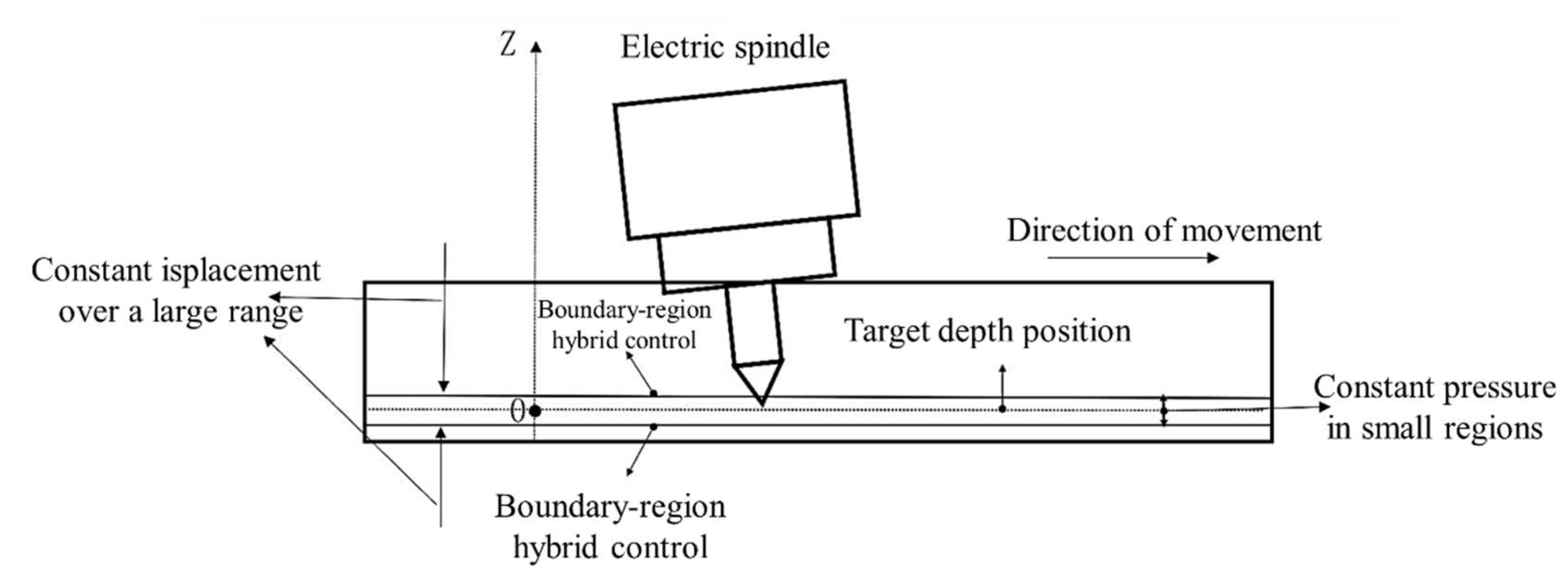
The force/position hybrid control strategy combines the advantages of constant displacement control and constant pressure control. It allows for flexible adjustment of depth and pressure during the processing of complex welded workpieces, meeting varying welding requirements. It adjusts the priority between force and position control, ensures constant displacement control over a large range while employing constant pressure control in small ranges to maintain welding quality. The force/position hybrid control divides the control areas reasonably, combining PID regulation and Dirichlet integral models. This approach not only ensures welding stability but also improves the quality of the weld seam.
In this research, the hybrid control strategy prioritizes constant displacement control, ensuring that the stirring tool tip remains within the designated displacement control range throughout the welding process. Global control is achieved through dynamic robot offset to adjust depth, while local control fine-tunes axial forging pressure by adjusting the tool tip position within a smaller control region. The overall strategy follows a structured spatial division: in large-scale regions, constant displacement control ensures proper weld formation; in localized regions, constant pressure control maintains weld quality; and in boundary zones, hybrid control stabilizes the process. The space division is shown in
Figure 17.
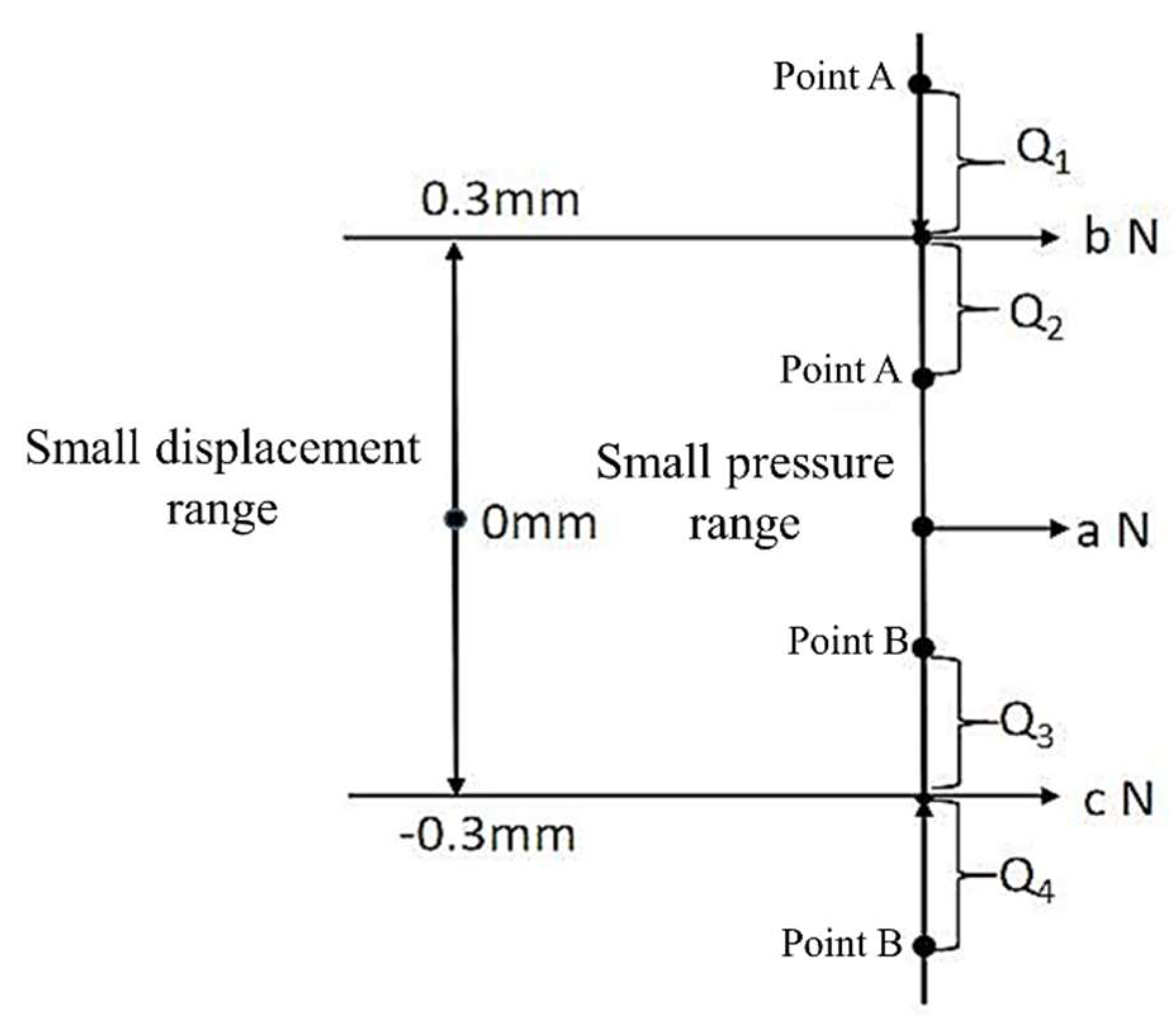
The target depth position is set as the Z-axis coordinate zero point, with constant displacement control applied over a large range. Outside the defined critical point, displacement control is used, while within the critical range, constant displacement control is disabled. The small-range interval for constant displacement is set within ±0.3mm on the Z-axis. The large range is divided into multiple stages, each controlled by a Dirichlet integral model. In small intervals, a constant pressure control model is applied, with the pressure adjusted within a target range of 90%-110% using a PI controller. However, during actual welding, the boundaries for the constant pressure control and constant displacement control do not overlap, requiring hybrid control. Therefore, a classification-based approach is necessary for this case.
As shown in
Figure 18, the upper boundary point of the small pressure range is A, with a pressure value of 90% a N. The corresponding pressure at the upper boundary of the small displacement range (0.3mm) is b N. Theoretically, due to the inhomogeneity of the material density in the weld, two cases (Q1 and Q2) are discussed. In the Q1 region, where the pressure at point A is greater than b N, a hybrid control method combining force and displacement is used. The output formula is shown in Equation (1), where Z1 and Z2 represent the dynamic offsets for displacement and pressure control, and
α and
β are the control coefficients. Since displacement control takes priority over pressure control, α > β. In the Q2 region, where the pressure at point A is less than b N, the hybrid control scheme is still applied, ensuring that the welding position remains within the small displacement range. Output coefficients α and β can be adjusted accordingly. The same approach is applied to regions Q3 and Q4, which are not analyzed further.
The control strategy for the hybrid system combines the constant displacement system and constant pressure system. The displacement output coefficients are designed as shown in
Table 2, where the displacement output coefficient for the constant displacement system is
Xij (odd-numbered rows), and for the constant pressure system, it is
Yij (even-numbered rows). During the hybrid control welding process, both the pressure and position control systems operate simultaneously, with the displacement output being a superposition of both. The expression is given in Equation (2), where x and a are the correction coefficients and step sizes for displacement control, and y and b are the correction coefficients and step sizes for pressure control.
The hybrid control system utilizes a large-range constant displacement control, small-range constant pressure control, and a force-position combined control strategy in the transition region. Based on the shoulder plunge depth and top forging pressure changes during welding, the constant displacement system controls large ranges in the intervals (0.5, +∞) and (-∞, -0.5), while the transition zone for force-position control is in the intervals (0.3, 0.5] and [-0.5, -0.3]. The small range is controlled in the [-0.3, 0.3] interval. The constant pressure system controls large ranges in the intervals (-100%, -8%) and (8%, +∞), with the transition zones being [-8%, -5%) and (5%, 8%], and the small range being [-5%, 5%].
For example, when the welding position is in the (0.3, 0.5] range and the pressure is in the [-8%, -5%) range, the output displacement can be expressed by Equation (3), realizing hybrid control during the welding process.
4. Robotic Friction Stir Welding Control System Software Design
To meet the requirements of robotic friction stir welding (FSW), this research develops an open, scalable control software system based on the GTRobot platform. The system integrates core modules, including electric spindle control, human-in-the-loop control, constant displacement, constant pressure, and force-position hybrid control, providing a complete hardware-software solution for large, thin-walled, complex curved surface welding. Offline programming methods are employed for welding trajectory design and simulation, enabling precise planning and visualization of 3D welds.
The open robotic control system supports secondary development and multi-mode motion control. According to IEEE definitions, such a system should feature expandability, portability, interoperability, and modularity. However, many industrial robot controllers on the market are specialized and lack these capabilities.
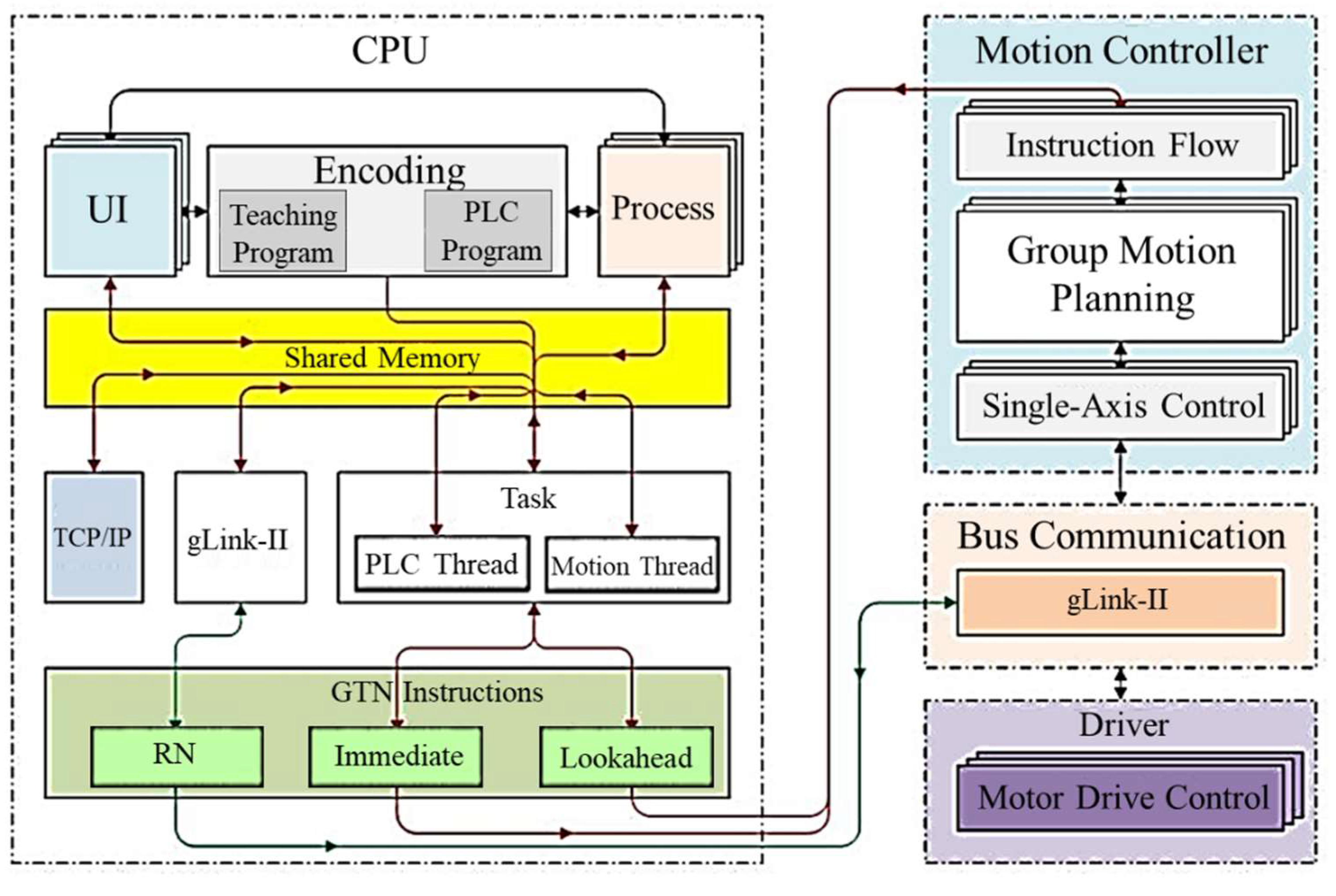
To address challenges in welding large curved surfaces, the GTRobot open, reconfigurable control platform (
Figure 19) is employed. Built on the Windows CE operating system with a DSP/ARM motion control layer, it ensures high real-time performance and reliability. The platform supports expansion through external I/O modules and various communication protocols (e.g., ModBus TCP, TCP/UDP), enabling seamless integration of external sensors and robotic motion.
The GTRobot control system architecture is composed of three layers: the platform application layer (CPU), the motion control layer (DSP/ARM), and the drive layer. The platform application layer, implemented in C/C++, handles human-machine interaction (UI/HMI), task management, and communication processes. The motion control layer executes high-real-time calculations such as trajectory planning and kinematics/dynamics. The drive layer ensures stable robot movement under high load by controlling power output and joint motors.
Secondary development is focused on the platform application layer, using tools like VS2008, QT4.7.3, and GUCN455CE6SDK to compile and debug code. Custom plugins (dll) are integrated into the main program (GTRobot.exe), with the process involving WinCE environment configuration, project creation, library/resource setup, and C++ programming.
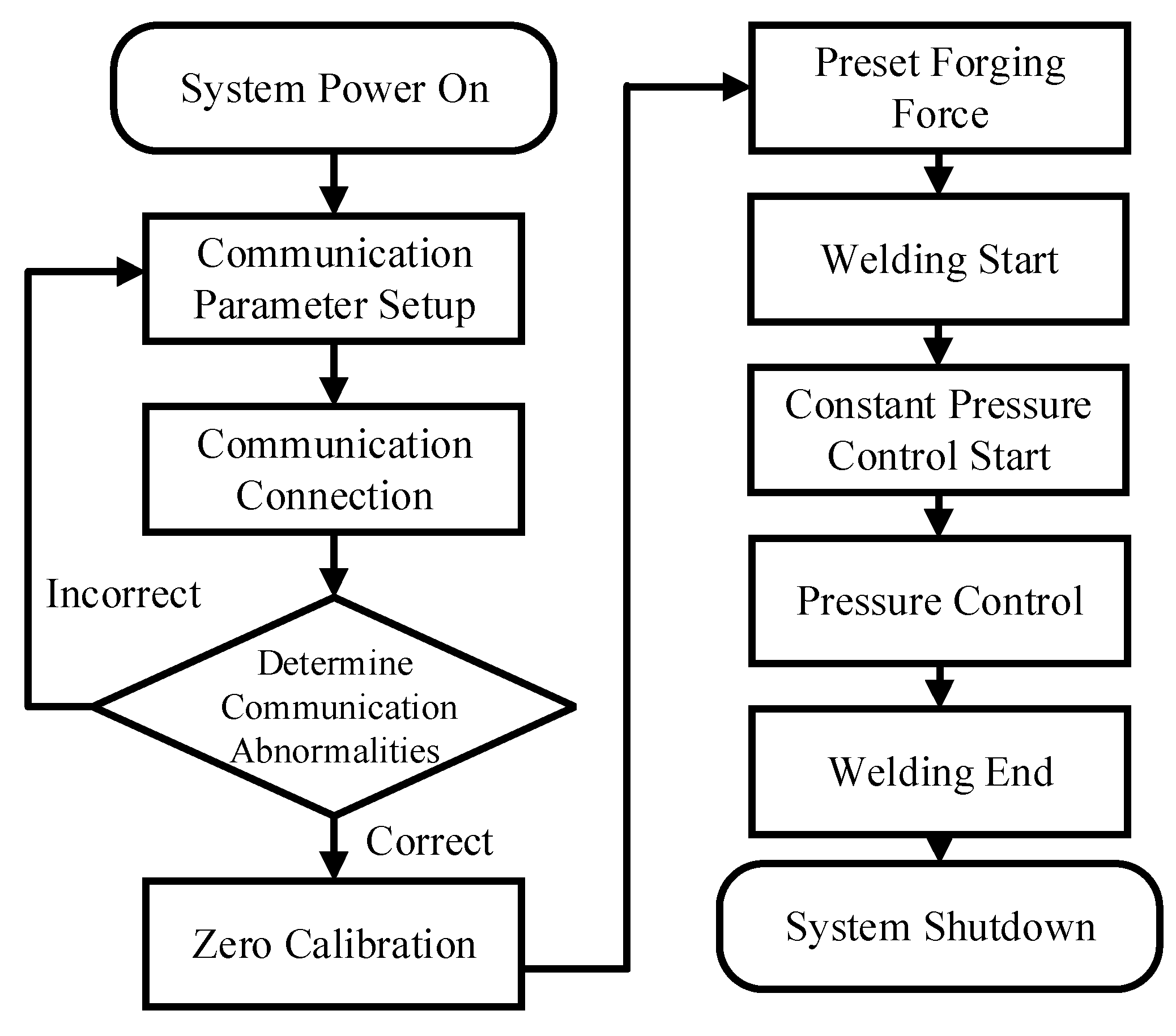
Force-position control is critical for friction stir welding, enabling real-time adjustments of parameters such as ’upset force’ and ’downward displacement.’ The constant pressure control module uses force sensors to measure axial force and compares it to the set value. If deviations occur, the system issues position offset commands to maintain a constant upset force. The backend UML structure, where the PLC periodically queries the sensor, parses the data, and adjusts displacement through the pressure_control() function, forms a closed-loop process. The software control process of the constant voltage system is shown in
Figure 20.
The constant displacement module uses a laser sensor’s voltage signal (0-5V) to monitor displacement, and robot offsets ensure consistent insertion force. The frontend interface includes voltage collection, board thickness settings, and calibration controls. The backend reads voltage via GTR_GetAiValue(double &value, const short index, short type) and compensates based on the displacement model (DoOffset).
Hybrid control combines pressure and position signals to maintain weld pool flow and consistent heat input in complex scenarios. The frontend interface offers settings for force-position ratio and coordinate correction. The backend registers two PLC threads to collect real-time pressure and position data, using a dynamic matrix algorithm (pressure_control + position_control) for decision-making and corrections, ensuring system flexibility and stability. After comprehensive analysis, the back-end program operation of the force-position hybrid system is shown in
Figure 21.
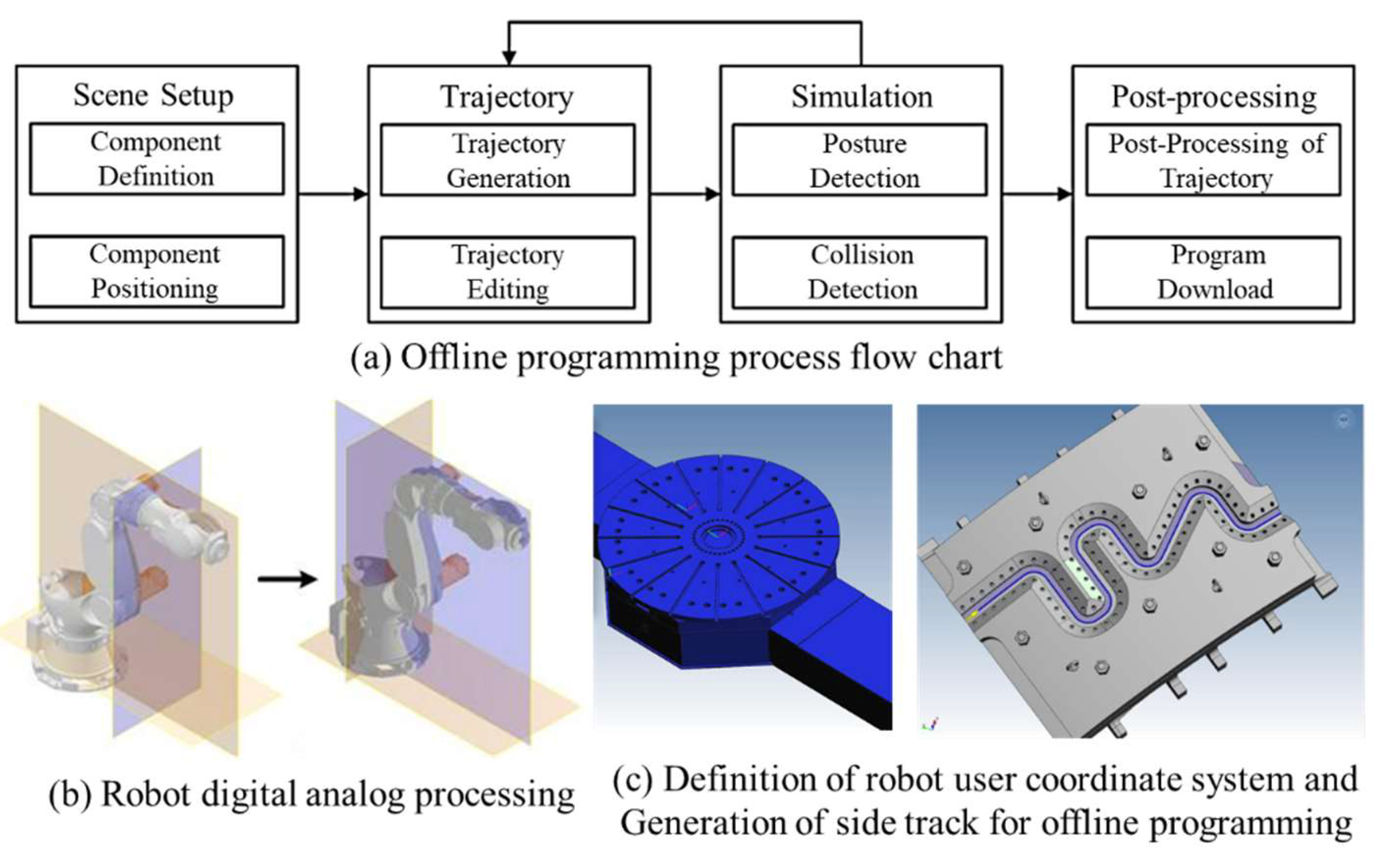
For spatial surface welding, which is difficult due to teaching programming challenges, PQArt offline programming software is used for modeling and trajectory planning. In PQArt, several coordinate systems must be defined, and welding paths are generated with options like “edge trajectory”. Parameters such as step size, fixed Z-axis, and tilt angle are added.
Figure 22 shows how trajectory speed, instruction type, and path optimization are specified.
Trajectory editing includes operations such as translation, rotation, Z-axis fixation, and coordinated motion, effectively addressing issues like “inaccessibility” and “axis over-limit” while enabling coordinate mapping for positioner-linked scenarios. After editing, robot motion can be simulated within the software.
Figure 23 illustrates the robot’s posture in the offline simulation, and once collision-free, an executable file can be generated and downloaded to the robot system for execution.
5. Experimental Results
5.1. Plane Linear Trajectory Process Welding Experiment
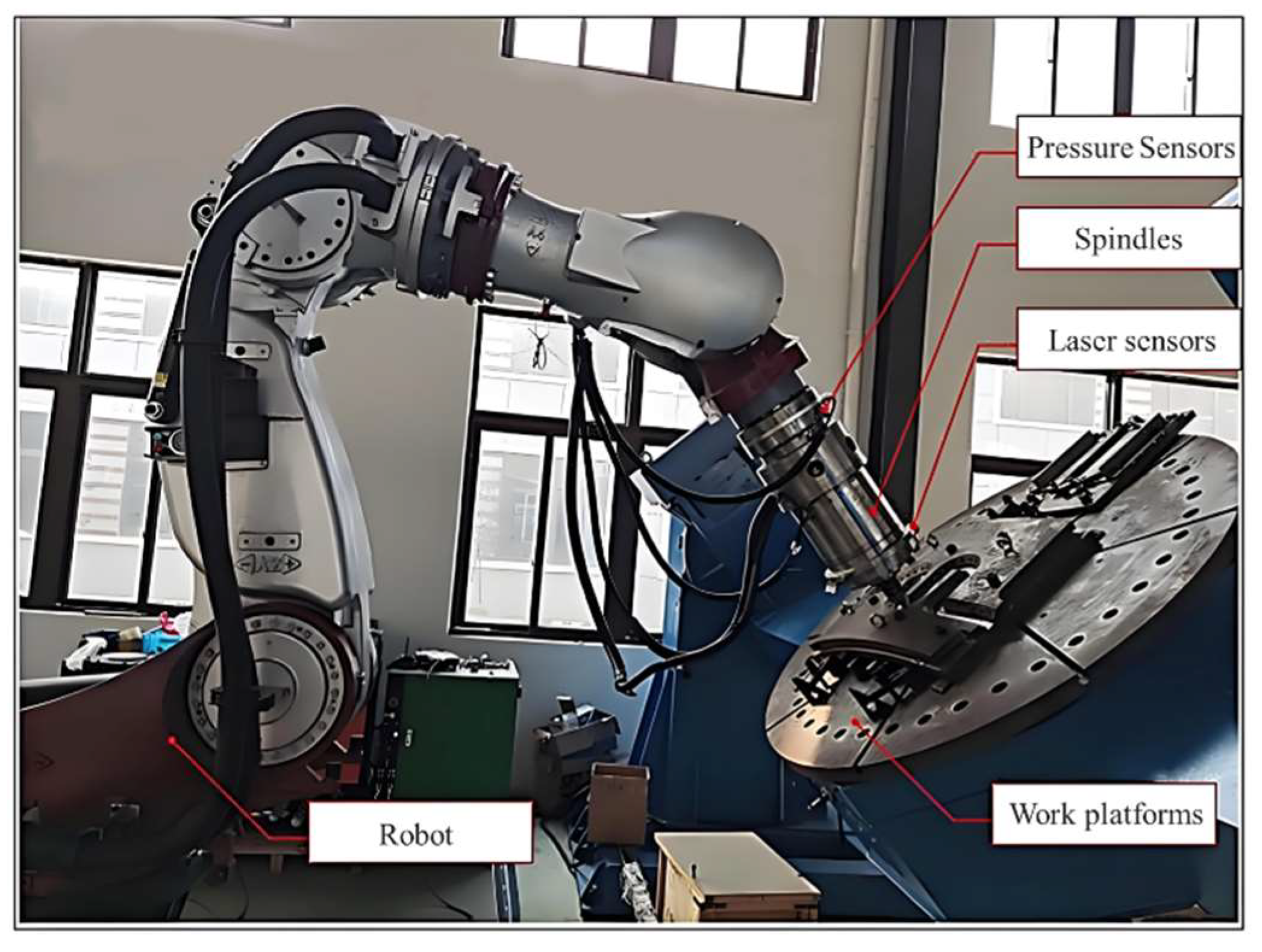
A planar linear trajectory welding experiment was conducted to validate the robot’s force-position control performance. The experimental platform is shown in
Figure 24.
Using the control variable method, we compared three modes: constant preload control, constant displacement control, and force-position hybrid control. Welding data was collected and analyzed to evaluate the effectiveness of the system. Depth compensation was used during trajectory interpolation because the potential deformation of the robot affects the depth of machining. Comparative experiments were conducted for weld depths of 7 mm and 10 mm with the process parameters shown in
Table 3. As shown in
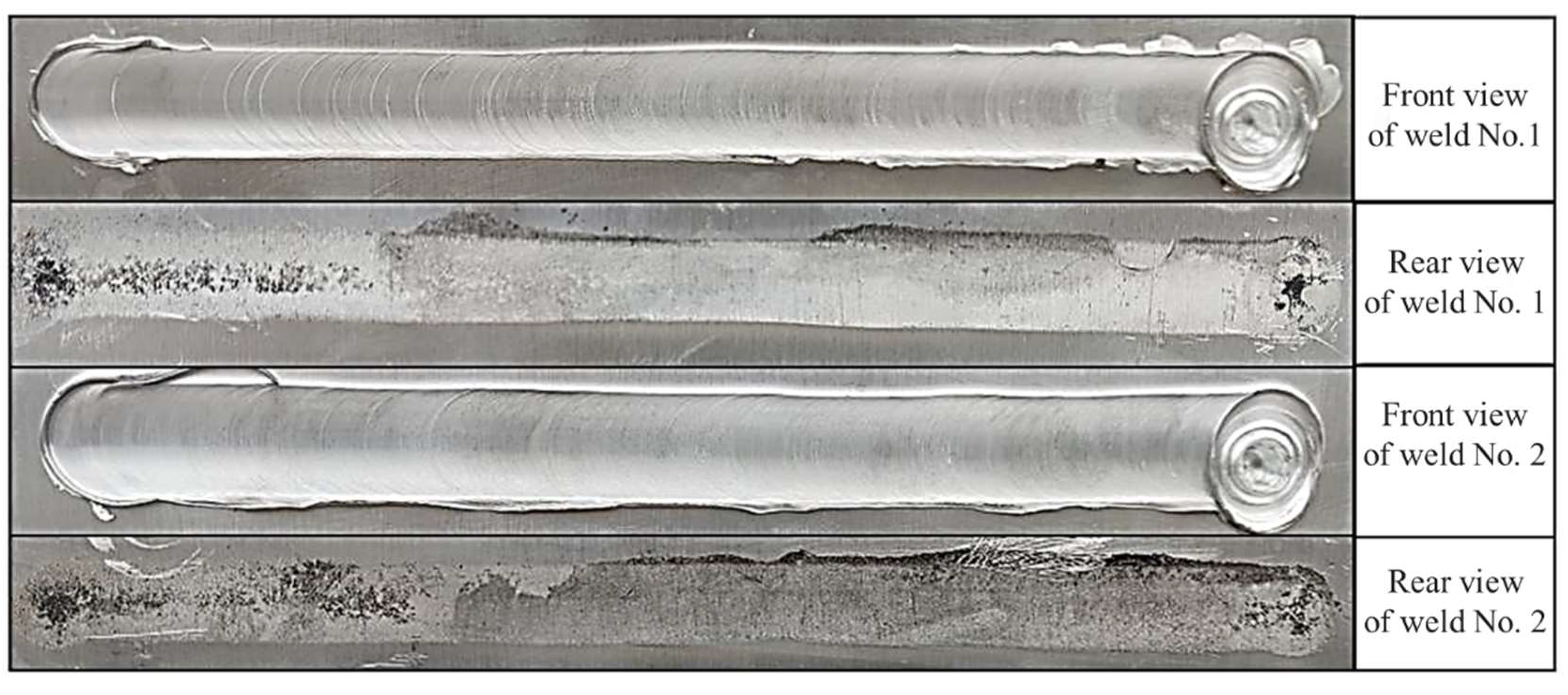
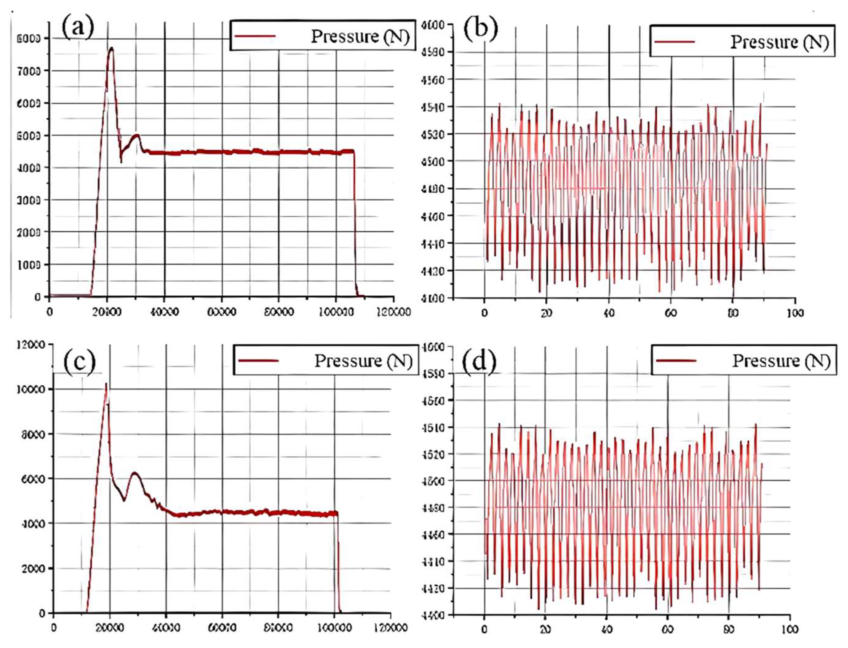
Figure 25 and
Figure 26, the pressure was varied between 4546N and 4409N with a maximum control error of 2.02%.
The constant displacement control experiment regulated depth positioning to ensure welding head stability. A 5mm-thick 2219 aluminum alloy plate was used, with initial compensation depths of 7mm and 10mm for comparison. The preset shoulder penetration depth was 0.1mm, corresponding to a calibrated voltage of 1.1V. Experimental parameters are listed in
Table 4.
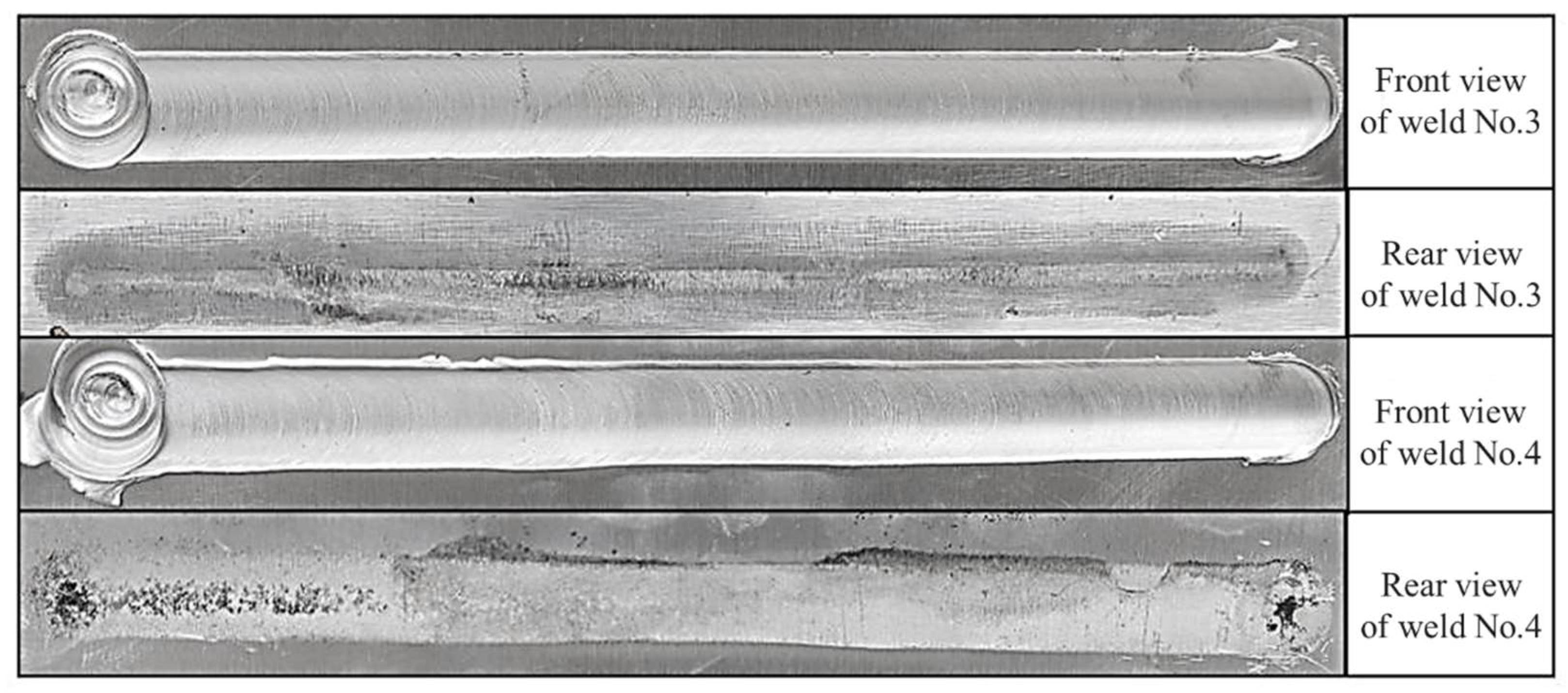
Results, as shown in
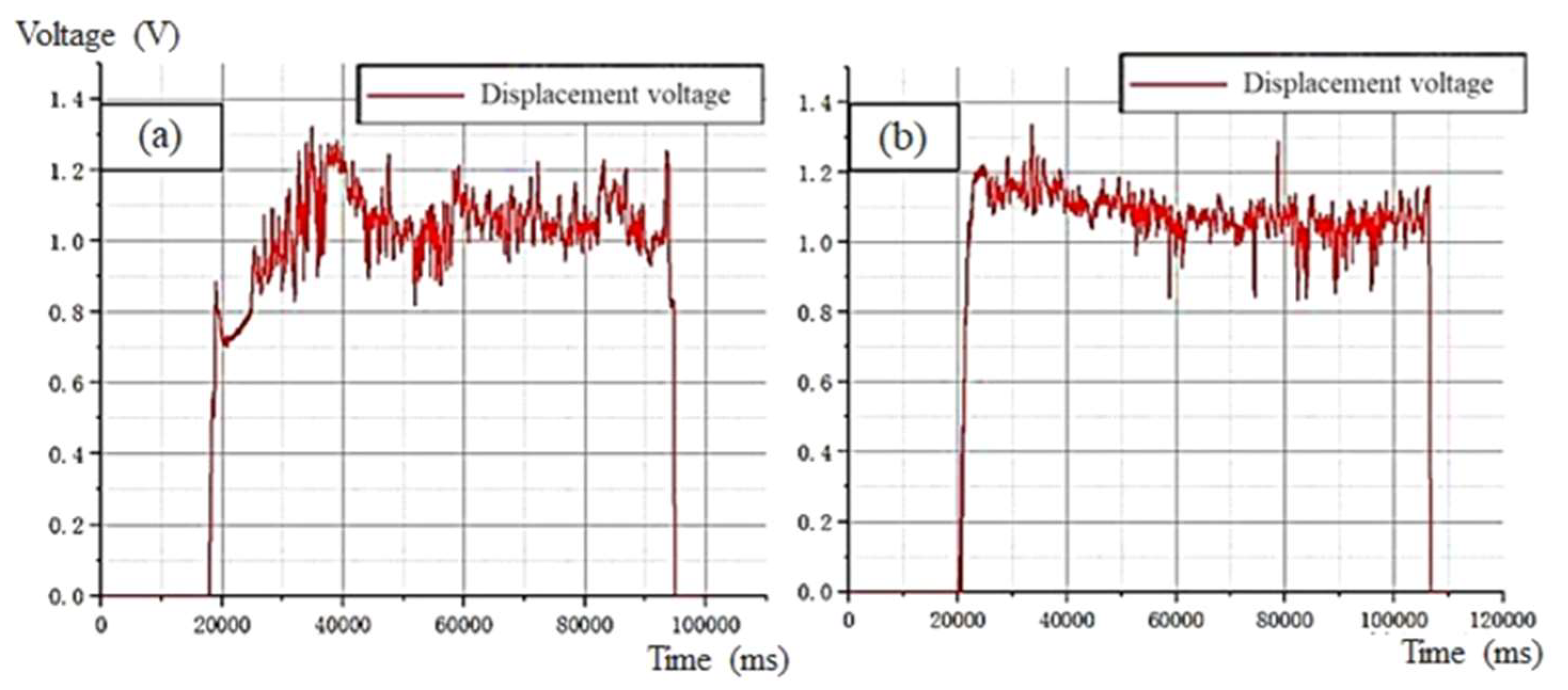
Figure 27 and
Figure 28, demonstrate that constant displacement control effectively minimized depth deviation, producing smooth, uniform welds with significant improvement over uncontrolled welding. Weld seam No.3 was smooth with moderate concavity, while weld seam No.4 exhibited slight initial flash but maintained uniformity. Both welds showed minor adhesion on the back.
During control, displacement voltage ranged from 1.32V to 0.82V, with a maximum error of 0.22mm. For process 6, voltage ranged from 1.38V to 0.81V, with a maximum error of 0.29mm. The system maintained accuracy within the preset 0.3mm threshold, meeting control requirements effectively.
The force-position hybrid control experiment combines constant pressure and constant displacement control to improve welding quality. Using a 5mm thick 2219-series aluminum alloy plate, the experiment sets an initial compensation depth of 7mm, with a depth position voltage of 1.1V and a calibration top forging pressure of 4500N, as shown in
Table 5.
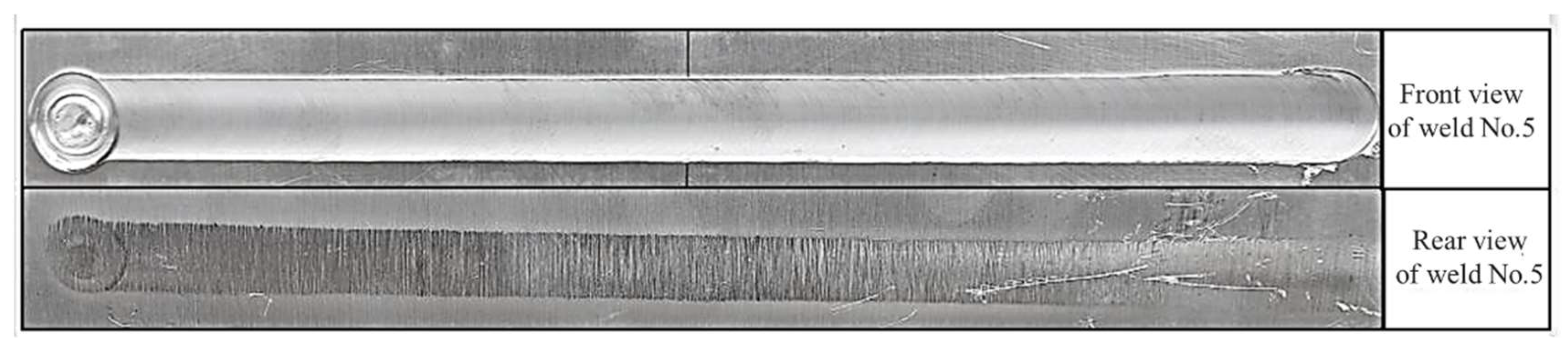
The resulting welds were organized, as shown in
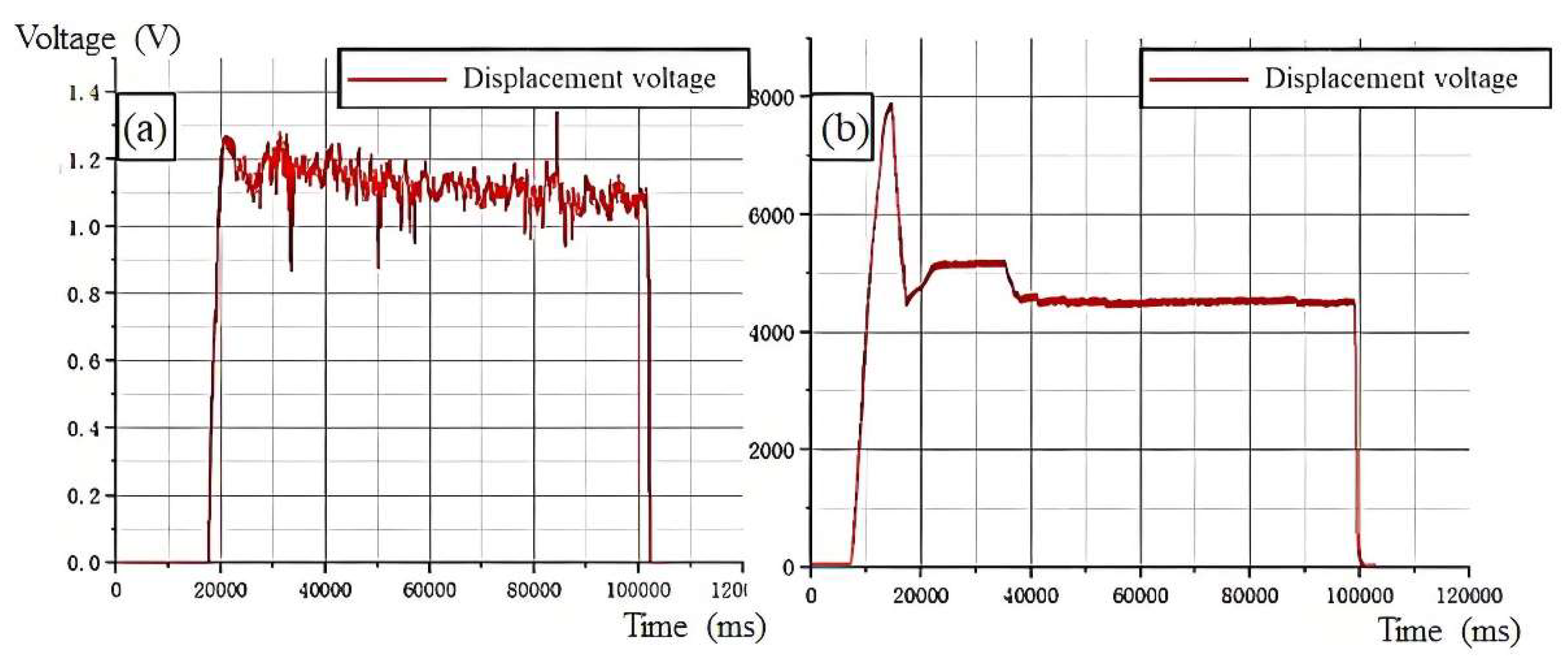
Figure 29. Compared to the uncontrolled welding, hybrid control significantly improved weld formation. On the weld’s front, the surface was smooth and flat with minimal concavity and uniform edge spatter; on the back, no tool attachment occurred, and the weld width was consistent. After the experiment, the depth displacement voltage and pressure data were processed and plotted, as shown in
Figure 30.
According to the position sensor’s calibration principle, when the stirring head contacts the workpiece, the voltage remains at 0V, and pressure increases until the shoulder is 1mm from the workpiece, after which the position voltage rises and pressure decreases as the stirring head moves to the initial compensation depth. During stable control, the maximum pressure fluctuation was 4597N, with an error rate of 2.21%, within the 5% pressure control range. The maximum displacement fluctuation was 0.86V, with an error of 0.24mm, within the 0.3mm control range. Overall, the hybrid control system met the required performance standards.
5.2. Validation of Welding Systems for Complex Curved Trajectories in Space
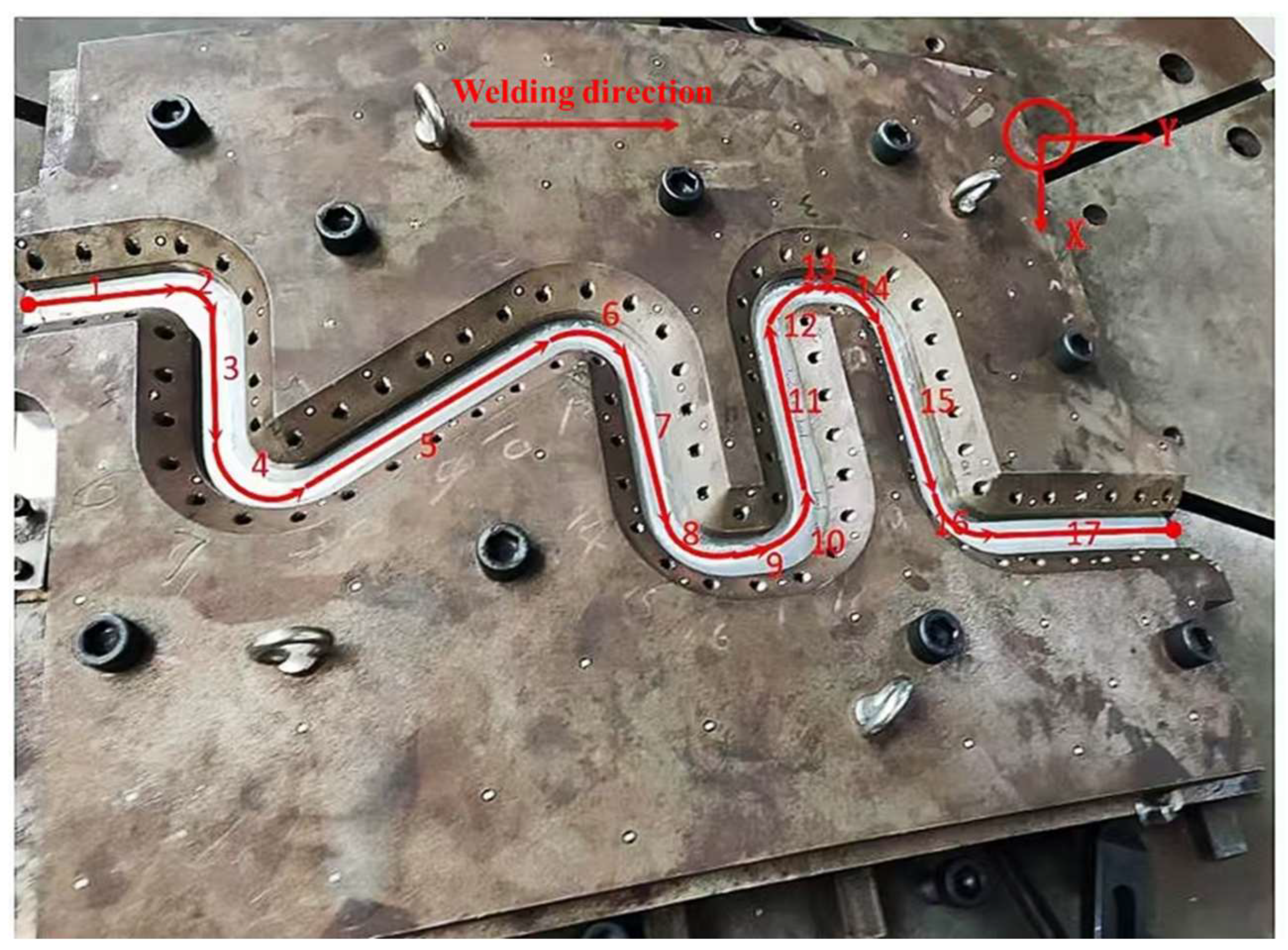
The welding experiment focuses on a complex curved wall panel—satellite radiator, commonly used in satellites. As shown in
Figure 31, the welding fixture and trajectory schematic for the satellite radiator are illustrated. The main material of the satellite radiator is 5A06-T6 aluminum alloy with a thickness of 4mm. The satellite radiator welding process involves three key points: (1) ensuring the robot follows the welding trajectory without position deviation, (2) real-time control of the welding depth, and (3) maintaining a stable relative posture to the weld seam with a forward tilt angle of approximately 2.5° throughout the welding trajectory. However, controlling the forward tilt angle via teaching is challenging and can be addressed using offline programming. Welding process parameters are provided in
Table 6.
Based on the workpiece coordinate system, the welding space is divided into X, Y, and Z directions. The trajectory is divided into 17 segments based on curvature, with Class 1 trajectories having lower curvature (1, 3, 5, 7, 9, 11, 13, 15, 17) and Class 2 trajectories having higher curvature (2, 4, 6, 8, 10, 12, 14, 16). The welding experiment is based on this control scheme, starting with the design of welding trajectories and posture. The generated trajectory is imported into the robot control system, with attention to the code format compatibility for the turntable and the proper back-end code sample.
The welding system’s online control scheme is established based on trajectory segments and time-sequenced process parameters. The trajectory is divided into 17 segments, with specific force-position control parameters applied to each of the X, Y, and Z directions. The X direction adjusts welding speed, the Y direction uses human-in-the-loop manual corrections, and the Z direction uses force-position hybrid control and position calibration voltage adjustments. The Class 1 trajectories have slower Z-direction displacement changes due to their lower curvature, while Class 2 trajectories have faster Z-direction displacement changes, allowing for adjustments in displacement control based on trajectory curvature.
In addition, some parts of the welding trajectory include curved segments, where the robot is more likely to experience Y-direction deviations. To correct this, the robot’s speed is reduced, and human-in-the-loop control is applied.
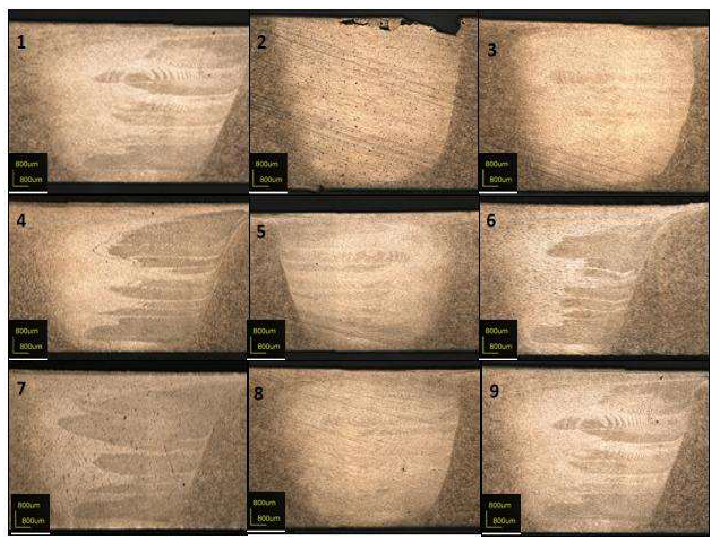
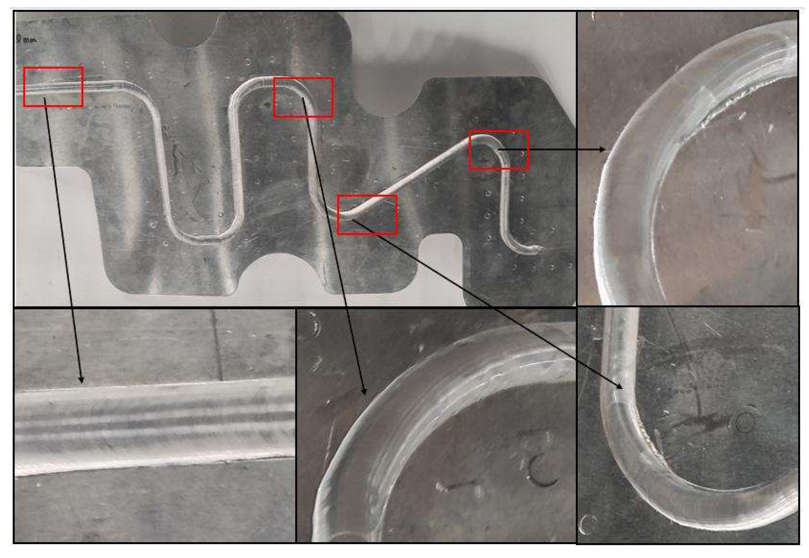
Figure 32 shows the macro appearance of the welding seam formed on a complex spatial curve, demonstrating generally good weld formation with minor edge defects in some high-curvature trajectory segments. Nine characteristic points are selected for cutting and microscopic observation, as shown in
Figure 33, where the cross-section of the weld is fully fused with no cracks, confirming the effectiveness of the friction stir welding system. A follow-up experiment on welding a 2mm thick satellite radiator produced a weld seam with favorable macroscopic appearance, as shown in
Figure 34.
6. Conclusion
The study aimed at welding complex curved components in aerospace space capsules and analyzed the heat generation mechanism in robotic friction stir welding. A multi-degree-of-freedom robotic friction stir welding (RFSW) system was designed, integrated with a force/position hybrid control strategy, effectively addressed the challenges of welding large-scale curved aluminum alloy panels. Based on the system configuration, an eight-axis linkage system was studied, and the electric spindle was integrated into the welding control system to achieve an integrated control solution.
The research also explored the application of external sensing devices and the secondary development of the control system within the robotic control framework to develop a force-position control strategy for robotic friction stir welding. The proposed control system illustrated that combining constant displacement control for large ranges with constant pressure control for small ranges significantly improved weld seam uniformity and consistency.
With these functions in place, welding along complex spatial curved trajectories was successfully completed. Experimental validation on both planar and complex curved surfaces showed that (1) flexible deformation and positioning deviations were effectively compensated; (2) forging pressure and welding depth remained within a controllable tolerance (<5%); and (3) the resulting weld seams exhibited uniform morphology and reliable mechanical properties. This research supports the development of high-precision and highly reliable intelligent welding robotic systems, promoting the advancement of automated welding technology for complex curved structures in the aerospace manufacturing industry.
Author Contributions
Methodology, Yue Yu.; software, Wenjun Yan.; validation, Yue Yu; writing—original draft, Wenjun Yan; writing—review and editing, Yue Yu; supervision, Yue Yu. funding acquisition, Wenjun Yan. All authors have read and agreed to the published version of the manuscript.
Funding
This work was supported by Beijing Natural Science Foundation (Grant No. QY24092).
References
- Threadgill, P.L.; Leonard, A.J.; Shercliff, H.R.; Withers, P.J. Friction Stir Welding of Aluminium Alloys. Int. Mater. Rev. 2009, 54, 49–93. [Google Scholar] [CrossRef]
- Çam, G.; Mistikoglu, S. Recent Developments in Friction Stir Welding of Al-Alloys. J. Mater. Eng. Perform. 2014, 23, 1936–1953. [Google Scholar] [CrossRef]
- Bhushan, R.K.; Sharma, D. Green Welding for Various Similar and Dissimilar Metals and Alloys: Present Status and Future Possibilities. Adv. Compos. Hybrid Mater. 2019, 2, 389–406. [Google Scholar] [CrossRef]
- Ahmed, M.M.; El-Sayed Seleman, M.M.; Fydrych, D.; Çam, G. Friction stir welding of aluminum in the aerospace industry: the current progress and state-of-the-art review. Materials 2023, 16, 2971. [Google Scholar] [CrossRef]
- Thomas, W.M.; Nicholas, E.D. Friction stir welding for the transportation industries. Materials design 1997, 18, 269–273. [Google Scholar] [CrossRef]
- Lahti, K. FSW-possibilities in shipbuilding. Indian Welding Journal 2003, 33–37. [Google Scholar] [CrossRef]
- Luo, J.; Wang, X.J.; Wang, J.X. New technological methods and designs of stir head in resistance friction stir welding. Science and Technology of Welding and Joining 2009, 14, 650–654. [Google Scholar] [CrossRef]
- Akin, D.; Sullivan, B. A Survey of Serviceable Spacecraft Failures. In Proceedings of the AIAA Space 2001 Conference and Exposition, Albuquerque, NM, USA, 28–30 August 2001; p. 4540. [Google Scholar]
- Çam, G.; Javaheri, V.; Heidarzadeh, A. Advances in FSW and FSSW of Dissimilar Al-Alloy Plates. J. Adhes. Sci. Technol. 2023, 37, 162–194. [Google Scholar] [CrossRef]
- Zhao, J.; Gao, X.; Wang, Y.; Zhang, L.; Ma, Z. FSW Robot System Dimensional Optimization and Trajectory Planning Based on Soft Stiffness Indices. J. Manuf. Process. 2021, 63, 88–97. [Google Scholar] [CrossRef]
- Ding, Jeff, et al. “A Decade of Friction Stir Welding R and D at NASA’s Marshall Space Flight Center and a Glance into the Future.” (2006).
- Fehrenbacher, A.; Smith, C.B.; Duffie, N.A.; Ferrier, N.J.; Pfefferkorn, F.E.; Zinn, M.R. Combined Temperature and Force Control for Robotic Friction Stir Welding. J. Manuf. Sci. Eng. 2014, 136, 021007. [Google Scholar] [CrossRef]
- Hoyos, E.; Serna, M.C. Basic tool design guidelines for friction stir welding of aluminum alloys. Metals 2021, 11, 2042. [Google Scholar] [CrossRef]
- De Backer, J.; Bolmsjö, G. Deflection Model for Robotic Friction Stir Welding. Ind. Robot 2014, 41, 365–372. [Google Scholar] [CrossRef]
- Gao, X.; Li, M.; Wang, P.; Liu, Y.; Zhang, H. Strain-Based Multi-Dimensional Force Sensing System for Robotic Friction Stir Welding. Measurement 2024, 115101. [Google Scholar] [CrossRef]
- Cook, G.E.; Crawford, R.; Clark, D.E.; Strauss, A.M. Robotic Friction Stir Welding. Ind. Robot 2004, 31, 55–63. [Google Scholar] [CrossRef]
- Smith, C.B.; Hinrichs, J.F.; Crusan, W.A. Robotic Friction Stir Welding: The State of the Art. In Proceedings of the 4th Friction Stir Welding International Symposium, Park City, UT, USA, 14–16 May 2003. [Google Scholar]
- Mo, F.; Liu, Y.; Wang, J.; Zhang, X. A Framework for Manufacturing System Reconfiguration and Optimisation Utilising Digital Twins and Modular Artificial Intelligence. Robot. Comput.-Integr. Manuf. 2023, 82, 102524. [Google Scholar] [CrossRef]
- Kolegain, K.; Leonard, F.; Chevret, S.; Ben Attar, A.; Abba, G. Off-Line Path Programming for Three-Dimensional Robotic Friction Stir Welding Based on Bézier Curves. Ind. Robot 2018, 45, 669–678. [Google Scholar] [CrossRef]
- Kolegain, K.; Leonard, F.; Zimmer-Chevret, S.; Attar, A.B.; Abba, G. A Feedforward Deflection Compensation Scheme Coupled with an Offline Path Planning for Robotic Friction Stir Welding. IFAC-PapersOnLine 2018, 51, 728–733. [Google Scholar] [CrossRef]
- Zheng, C.; An, Y.; Wang, Z.; Wu, H.; Qin, X.; Eynard, B.; Zhang, Y. Hybrid Offline Programming Method for Robotic Welding Systems. Robot. Comput.-Integr. Manuf. 2022, 73, 102238. [Google Scholar] [CrossRef]
- Qin, J. (2013). Commande hybride position/force robuste d’un robot manipulateur utilisé en usinageet/ou en soudage (Doctoral dissertation, Ecole nationale supérieure d’arts et métiers-ENSAM).
- Gao, X.; Li, Z.; Zhao, H.; Dong, J.; Gao, H. Strain-based multi-dimensional force sensing system for robotic friction stir welding. Measurement 2024, 115101. [Google Scholar] [CrossRef]
- Kamm, V.; Lechler, A.; Verl, A. (2024, November). High Bandwidth Force Control for Robotic Friction Stir Welding. In 2024 7th Iberian Robotics Conference (ROBOT) (pp. 1–7). IEEE.
- Nielsen, I.; Garpinger, O.; Cederqvist, L. Simulation-Based Evaluation of a Nonlinear Model Predictive Controller for Friction Stir Welding of Nuclear Waste Canisters. In Proceedings of the 2013 European Control Conference (ECC), Zürich, Switzerland, 17–19 July 2013; pp. 2074–2079. [Google Scholar]
- Longhurst, W.R.; Strauss, A.M.; Cook, G.E. The Identification of the Key Enablers for Force Control of Robotic Friction Stir Welding. Proc. Inst. Mech. Eng. Part B J. Eng. Manuf. 2010, 224, 937–949. [Google Scholar] [CrossRef]
- Xiao, J.; Wang, M.; Liu, H.; Liu, S.; Zhao, H.; Gao, J. A constant plunge depth control strategy for robotic FSW based on online trajectory generation. Robotics and Computer-Integrated Manufacturing 2023, 80, 102479. [Google Scholar] [CrossRef]
- Kolegain, K.; Leonard, F.; Zimmer-Chevret, S.; Attar, A.B.; Abba, G. A feedforward deflection compensation scheme coupled with an offline path planning for robotic friction stir welding. IFAC-PapersOnLine 2018, 51, 728–733. [Google Scholar] [CrossRef]
- Guillo, M.; Dubourg, L. Impact & improvement of tool deviation in friction stir welding: Weld quality & real-time compensation on an industrial robot. Robotics and Computer-Integrated Manufacturing 2016, 39, 22–31. [Google Scholar]
- Mendes, N.; Neto, P.; Simão, M.A.; Loureiro, A.; Pires, J.N. A Novel Friction Stir Welding Robotic Platform: Welding Polymeric Materials. Int. J. Adv. Manuf. Technol. 2016, 85, 37–46. [Google Scholar] [CrossRef]
- Longhurst, W.R.; Strauss, A.M.; Cook, G.E. Enabling Automation of Friction Stir Welding: The Modulation of Weld Seam Input Energy by Traverse Speed Force Control. Proc. Inst. Mech. Eng. Part B J. Eng. Manuf. 2010, 224, 937–949. [Google Scholar] [CrossRef]
- Longhurst, W.R.; Strauss, A.M.; Cook, G.E. (2010). Enabling automation of friction stir welding: the modulation of weld seam input energy by traverse speed force control.
- Yoon, J.; Kim, C.; Rhee, S. Compensation of Vertical Position Error Using a Force–Deflection Model in Friction Stir Spot Welding. Metals 2018, 8, 1049. [Google Scholar] [CrossRef]
- Raibert, M.H.; Craig, J.J. Hybrid Position/Force Control of Manipulators. J. Manuf. Sci. Eng. 1981, 136. [Google Scholar] [CrossRef]
- Smith, C.B. Robotic Friction Stir Welding Using a Standard Industrial Robot. In Proceedings of the 2nd Friction Stir Welding International Symposium, Gothenburg, Sweden, 2000. [Google Scholar]
Figure 1.
Composition and structure of RSFW system.
Figure 1.
Composition and structure of RSFW system.
Figure 2.
Composition and structure of robot friction stir welding system.
Figure 2.
Composition and structure of robot friction stir welding system.
Figure 3.
Offline model of eight axis linkage system.
Figure 3.
Offline model of eight axis linkage system.
Figure 4.
Physical appearance of motorized spindle for robot friction stir welding.
Figure 4.
Physical appearance of motorized spindle for robot friction stir welding.
Figure 5.
Signal acquisition diagram of six-dimensional force sensor.
Figure 5.
Signal acquisition diagram of six-dimensional force sensor.
Figure 6.
Calibration test of pressure sensor.
Figure 6.
Calibration test of pressure sensor.
Figure 7.
Installation diagram of point laser sensor.
Figure 7.
Installation diagram of point laser sensor.
Figure 8.
Calibration model of laser sensor.
Figure 8.
Calibration model of laser sensor.
Figure 9.
Design of laser sensor calibration process.
Figure 9.
Design of laser sensor calibration process.
Figure 10.
Process coordinate system.
Figure 10.
Process coordinate system.
Figure 11.
Two correction modes and Two position correction schemes for multi-stage trajectory welding a) Relative correction b) Absolute correction c) Trajectory discontinuity correction scheme d) Trajectory continuous.
Figure 11.
Two correction modes and Two position correction schemes for multi-stage trajectory welding a) Relative correction b) Absolute correction c) Trajectory discontinuity correction scheme d) Trajectory continuous.
Figure 12.
Analysis of welding acquisition points.
Figure 12.
Analysis of welding acquisition points.
Figure 13.
System hardware construction.
Figure 13.
System hardware construction.
Figure 14.
Control model of constant displacement system.
Figure 14.
Control model of constant displacement system.
Figure 15.
Hardware model of constant pressure control system.
Figure 15.
Hardware model of constant pressure control system.
Figure 16.
Constant pressure control model.
Figure 16.
Constant pressure control model.
Figure 17.
Design of hybrid control section.
Figure 17.
Design of hybrid control section.
Figure 18.
Design of hybrid control section.
Figure 18.
Design of hybrid control section.
Figure 19.
Design of hybrid control section.
Figure 19.
Design of hybrid control section.
Figure 20.
Software control flow of constant pressure system.
Figure 20.
Software control flow of constant pressure system.
Figure 21.
Operation flow of back-end program of hybrid control system.
Figure 21.
Operation flow of back-end program of hybrid control system.
Figure 22.
Schematic diagram of trajectory speed, command type, path optimization and key parameter settings in PQArt software spatial surface welding application.
Figure 22.
Schematic diagram of trajectory speed, command type, path optimization and key parameter settings in PQArt software spatial surface welding application.
Figure 23.
Schematic diagram of trajectory speed, command type, path optimization and key parameter settings in PQArt software spatial surface welding application.
Figure 23.
Schematic diagram of trajectory speed, command type, path optimization and key parameter settings in PQArt software spatial surface welding application.
Figure 24.
Welding experiment platform.
Figure 24.
Welding experiment platform.
Figure 25.
Forming surface of weld under constant pressure control.
Figure 25.
Forming surface of weld under constant pressure control.
Figure 26.
Variation diagram of welding pressure under constant pressure control. a) Pressure data curve in the whole process of No. 1 welding experiment b) Pressure data curve in the stability control stage of No. 1 welding experiment c) Pressure data curve in the whole process of No. 2 welding experiment d) Pressure data curve in the stability control stage of No. 2 welding experiment.
Figure 27.
Forming surface of weld under constant pressure control.
Figure 27.
Forming surface of weld under constant pressure control.
Figure 28.
Variation diagram of depth voltage in constant displacement control welding process. (a) Displacement voltage data curve of No. 3 welding experiment (b)Displacement voltage data curve of No. 4 welding experiment.
Figure 28.
Variation diagram of depth voltage in constant displacement control welding process. (a) Displacement voltage data curve of No. 3 welding experiment (b)Displacement voltage data curve of No. 4 welding experiment.
Figure 29.
Mixed control weld forming surface.
Figure 29.
Mixed control weld forming surface.
Figure 30.
Variation curve of force level data in the whole process of hybrid control welding.
Figure 30.
Variation curve of force level data in the whole process of hybrid control welding.
Figure 31.
Variation curve of force level data in the whole process of hybrid control welding.
Figure 31.
Variation curve of force level data in the whole process of hybrid control welding.
Figure 32.
Welding surface morphology of satellite radiator with thickness of 4mm.
Figure 32.
Welding surface morphology of satellite radiator with thickness of 4mm.
Figure 33.
Weld crystal phase diagram.
Figure 33.
Weld crystal phase diagram.
Figure 34.
Welding surface morphology of satellite radiator with thickness of 2mm.
Figure 34.
Welding surface morphology of satellite radiator with thickness of 2mm.
Table 1.
Main parameters of the spindle.
Table 1.
Main parameters of the spindle.
| Indicator Name |
Indicator Data |
| Rated Speed |
5000 rpm |
| Power |
29 kW |
| Maximum Axial Load |
5000 N |
| Equipped with Water Cooling System |
Ensures long-term stable operation |
Table 2.
Displacement output dynamic matrix of hybrid control system.
Table 2.
Displacement output dynamic matrix of hybrid control system.
| |
Number |
(-100%,-8%) |
[-8%,-5%) |
[-5%,5%) |
[-5%,8%) |
(5%,8%) |
(8%,+∞) |
| (0.5, +∞) |
1 |
X11
|
X12
|
X13
|
X14
|
X15
|
X16
|
| 2 |
Y11
|
Y12
|
Y13
|
Y14
|
Y15
|
Y16
|
| (0.3,0.5] |
3 |
X21
|
X22
|
X23
|
X24
|
X25
|
X26
|
| 4 |
Y21
|
Y22
|
Y23
|
Y24
|
Y25
|
Y26
|
| [-0.3,0.3] |
5 |
X31
|
X32
|
X33
|
X34
|
X35
|
X36
|
| 6 |
Y31
|
Y32
|
Y33
|
Y34
|
Y35
|
Y36
|
| [-0.5,-0.3) |
7 |
X41
|
X42
|
X43
|
X44
|
X45
|
X46
|
| 8 |
Y41
|
Y42
|
Y43
|
Y44
|
Y45
|
Y46
|
| (-∞,-0.5) |
9 |
X51
|
X52
|
X53
|
X54
|
X55
|
X56
|
| 10 |
Y51
|
Y52
|
Y53
|
Y54
|
Y55
|
Y56
|
Table 3.
Constant pre-pressure control process parameter table.
Table 3.
Constant pre-pressure control process parameter table.
| Number |
Plate Material |
Welding Speed |
Spindle Speed |
Pressing Speed |
Nominal Pressure |
| 1 |
2219 |
2mm/s |
1500r/min |
0.25mm/s |
4500N |
| 2 |
2219 |
2mm/s |
1500r/min |
0.25mm/s |
4500N |
Table 4.
Constant displacement control process parameter table.
Table 4.
Constant displacement control process parameter table.
| Number |
Plate Material |
Welding Speed |
Spindle Speed |
Initial Supplementary Depth |
Pressing Speed |
| 3 |
2219 |
2mm/s |
1500r/min |
7mm |
0.25mm/s |
| 4 |
2219 |
2mm/s |
1500r/min |
10mm |
0.25mm/s |
Table 5.
Hybrid Force-Position Control Process Parameter Table.
Table 5.
Hybrid Force-Position Control Process Parameter Table.
| Number |
Plate Material |
Welding Speed |
Spindle Speed |
Initial Supplementary Depth |
Pressing Speed |
| 5 |
2mm/s |
1500r/min |
7mm |
0.25mm/s |
1.1V |
Table 6.
Hybrid Force-Position Control Process Parameter Table.
Table 6.
Hybrid Force-Position Control Process Parameter Table.
| Workpiece Material |
Plate Thickness |
Welding Speed |
Spindle Speed |
Control Pressure |
Control Depth |
Trajectory Planning |
| 5A06-T6 |
4mm |
Segment Control |
1800r/min |
4500N |
Segment Control |
Off-line Programming |
|
Disclaimer/Publisher’s Note: The statements, opinions and data contained in all publications are solely those of the individual author(s) and contributor(s) and not of MDPI and/or the editor(s). MDPI and/or the editor(s) disclaim responsibility for any injury to people or property resulting from any ideas, methods, instructions or products referred to in the content. |
© 2025 by the authors. Licensee MDPI, Basel, Switzerland. This article is an open access article distributed under the terms and conditions of the Creative Commons Attribution (CC BY) license (http://creativecommons.org/licenses/by/4.0/).