
Submitted:
01 August 2023
Posted:
02 August 2023
You are already at the latest version
Abstract
The automation of welding processes requires the use of automated systems and equipment, in many cases industrial robotic systems, to carry out welding processes that previously required human intervention. Automation in the industry offers numerous advantages, such as increased efficiency and productivity, cost reduction, improved product quality, increased flexibility and safety, and greater adaptability of companies to market changes. The field of welding automation is currently undergoing a period of profound changes due to a combination of technological, regulatory, and economic factors worldwide. Nowadays, the most relevant aspect of the welding industry is to meet customer requirements by satisfying their needs. To achieve this, the automation of the welding process through sensors and control algorithms ensures the quality of the parts and prevents errors such as porosity, unfused areas, deformations, excessive heat, etc. This paper proposes an intelligent and adaptive system based on the measurement of welding joints using laser scanning and the subsequent analysis of the obtained point cloud to adapt the welding trajectories.
Keywords:
Welding
; robotics
; automation
; thick joints
1. Introduction
A welded joint is defined as the union of two or more elements, creating continuity through heat and/or pressure with or without the use of filler material. Currently, there are numerous welding processes available, such as Gas Metal Arc Welding (GMAW) with a consumable electrode, which is the wire itself [1]; Flux Cored Arc Welding (FCAW) [2]; Gas Tungsten Arc Welding (GTAW) [3], Submerged Arc Welding (SAW) [4], among others. Among these processes, GMAW technology is widely used and will be employed in this work.
In certain industries, known as heavy industries (naval industry, oil & gas sector, energy sector, etc.), many components are large-scale mechanized and welded structures. For example, in the naval industry, the construction of large ships, with lengths exceeding 24 m and internal volumes T.R.G. greater than 50, requires over 1000 hours of welding. These joints can present some difficulties [5], including: i) non-uniform and irregular pre-welded grooves, ii) the need for certified and qualified welding operators, iii) long deposition times, and iv) welding positions that require special skills. Furthermore, in these types of sectors, there is often high physical demand and risk for the operator.
Specifically, within the different types of joints, welding thick joints has been shown in the literature to be one of the most challenging to automate, as they require multiple layers of the deposited material to fill the joint [6]. Consequently, the current practice for manufacturing thick-component joints has largely been limited to manual welding processes. Thus, the automation of welding using robotic systems has become an inevitable trend for this type of joint.
Until now, two main alternatives have been proposed for automating this type of welding, but complete automation has not been achieved. In the first alternative, the predefined welding paths are established using robotic welding configurations based on computer-aided design (CAD) where the welding solution can be planned, programmed, modified, and simulated offline with precise robotic kinematics and ideal (nominal) dimensions of the welds [7]. These systems that program manufacturing in advance clearly cannot predict or take into account the deformations and contractions that these types of parts undergo during layer-by-layer welding. Furthermore, deviations in geometry present in pre-welded joints also cannot be considered by solely contemplating nominal dimensions that may not align with reality. Lastly, the exact positioning of the parts can also be inadequate due to incorrect assemblies or unforeseen displacements of the parts [8].
Secondly, there are methods based on scanning the joints and subsequently predicting the welding points, which generally consist of three stages. First, the geometric data of the joints are acquired through vision systems [9], and then it is processed to automatically select an optimal torch location. Next, precise tracking of the joints is performed, passing through the preselected optimal points [10]. Third, real-time defect detection is considered to assess if the welds meet quality control requirements [11]. These processes are complex due to the high degree of required automation and algorithmic complexity. Other factors that also affect these processes are reflection problems with vision systems during welding caused by spectral signals [12], the sound of the arc [13], or the molten pool that can alter the scanned profile [14]. Another significant challenge in automatic welding of thick plates is the contraction that the joint undergoes, leading to deformation as a result of high welding temperatures.
Among these methods, "click and go" solutions can be found, where the operator decides the most suitable welding point based on the information acquired by the vision system. This type of solution requires more operator intervention and can lead to errors, as the operator is presented with a limited set of profiles that may be insufficient to account for deformation along the entire joint. Additionally, manual point selection prolongs production time, making automatic selection through algorithms an improvement for the process, as it eliminates the need for an operator to select welding points for each layer.
In this work, following the mentioned approach, to provide a fully automated, intelligent, and adaptive solution for welding thick joints, an automatic robotic system equipped with a laser profilometer and an algorithm for finding optimal welding positions was proposed. Besides, this system also checks the robot's accessibility and movement consistency. More specifically, the main objective of this work was to define the torch's trajectory automatically for welding the first layer of a thick joint based on the profiles of the joints acquired by the laser profilometer.
2. Materials and Methods
2.1. Materials
To validate and illustrate the development carried out in this work, "T"-shaped joints made of thick mild steel plates for Oil & Gas sector applications were analyzed and welded. These types of joints have the geometry depicted in Figure 1b, featuring a double-beveled joint that was pre-welded at the corners to ensure minimal deformations. The thickness of the plates is 60 mm, and the bevel angle is 45 degrees. A commercially available ER70S-6 steel wire with a diameter of 1.2 mm was used for welding.
2.2. Set-Up
In this work, to develop the intelligent and adaptive welding system based on joint scanning, a robotic cell designed to provide precise and reliable welds was used, as shown in Figure 1a. This cell consists of the Titan XQ 400 AC Puls welding generator with BUSINTX11 Profibus interface (EWM), which powers the GMAW welding torch mounted on the Fanuc Arc Mate 100-iC robotic arm. This setup was also equipped with the M drive 4 Rob5 XR RE wire feeder (EWM) and the shielding gas system [15].
For joint scanning, the Queltech Q4-120 laser profilometer was installed on the welding torch. It is a high-precision device designed to measure the three-dimensional shape of objects. It has a range of 120 millimeters on the Z-axis, 70 millimeters on the X-axis, a working distance of 84 millimeters, and a resolution of 0.0798 millimeters. The scanning position of the robot can be seen in Figure 1c.
For welding, a 17 mm diameter nozzle and a Stick-out (the distance the wire extends from the nozzle) of 17 mm were used. As a shielding gas, a mixture of 80% argon and 20% carbon dioxide was introduced in the torch, with a flow rate of 17 L/min.
2.3. Data Acquisition Chain
To communicate the different elements that make up this intelligent and adaptive welding system, consisting of the robot, the monitoring application, the database, and the laser profilometer, a device-dependent communication configuration has been established, as shown in Figure 2a. In this system, process monitoring was carried out using an open-loop control. For this purpose, the laser profilometer has been installed as an external sensor, and the internal signals of the welding machine were also collected: intensity, voltage, wire feed speed, and travel speed. The positions of the robot axes and the wrist angles with respect to the coordinates of the workpiece were also monitored.
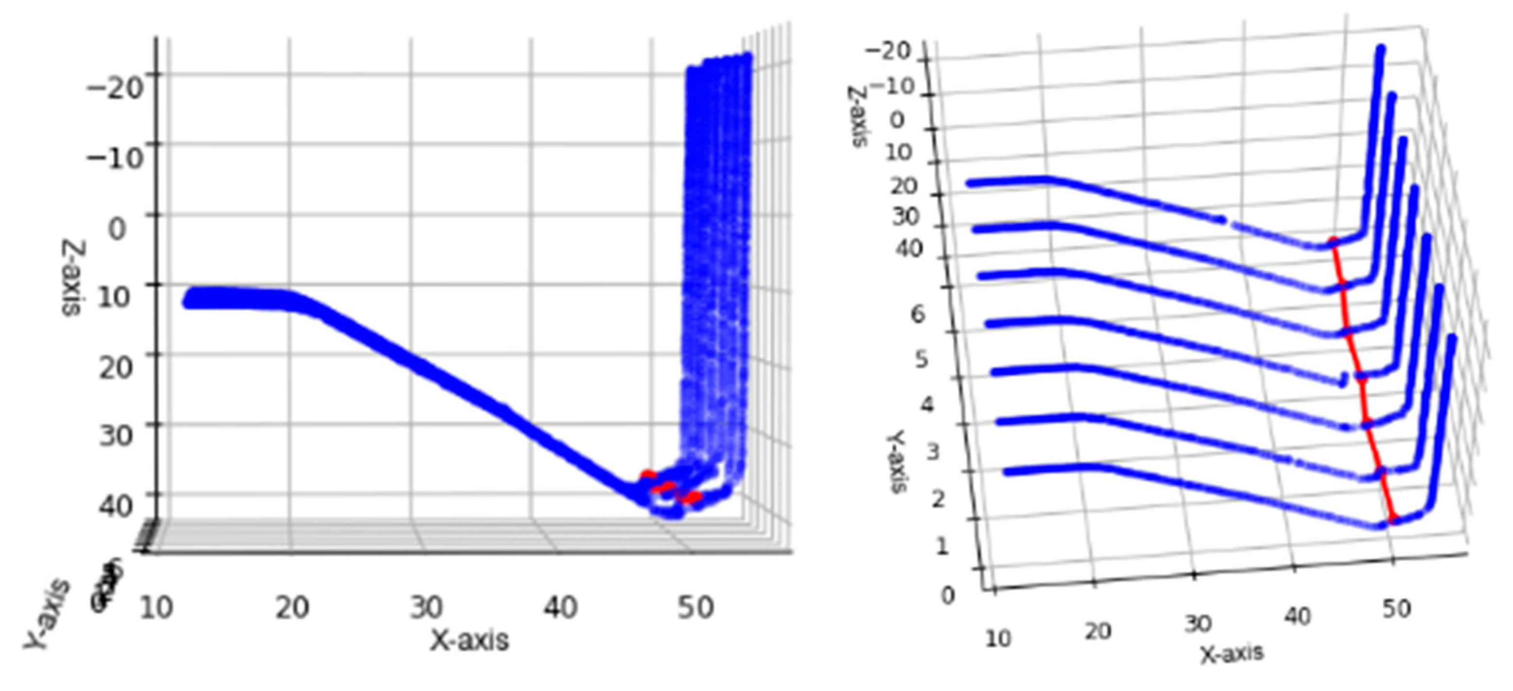
To initiate the process, a scanning sequence of the weld joint was performed with the robot in the position shown in Figure 1c, scanning the entire length of the joint. Figure 2b shows the 3D reconstruction of the joint based on the 2D profiles acquired by the laser profilometer. For each welding layer, a profile was stored every 20 mm scanned along the joint. From these profiles, the algorithm developed within this work calculates the welding points, i.e., the points that the torch will travel to weld the joint.
Figure 2c shows the point clouds of the equidistant discrete profiles recorded by the laser to cover the length of the joint. As seen in Figure 2c, there are different sources of uncertainty in defining the trajectory based on these profiles. On one hand, the point cloud may contain outliers that need to be removed through filtering. On the other hand, the profiles may exhibit misalignment, suggesting that the joint was not aligned with the laser trajectory. To build a robust system, the algorithm described in this article considers these difficulties, as well as potential joint deformations during welding.
3. Results
3.1. Influence of Welding Parameters
The welding process plays a crucial role in achieving strong and reliable joints, especially in applications involving thick plates and delicate ceramic components. In this study, we delve into the influential factors affecting the welding of the first layer of a joint subjected to a 45º bevel angle (Figure 1b). The primary objective of this initial layer is to effectively fill the gap of 3-4 mm between the thick plates housing the ceramic material, which demands precise control of the welding parameters. To enhance joint filling, we investigate the impact of introducing an oscillation in the welding trajectory. Additionally, we explore the significance of the torch orientation, as an improper inclination could lead to potential collisions with the joint walls. The nominal inclination of the torch stands at 22.5º, but this study involves an analysis of various inclination angles. Detailed information on the range of values examined for the oscillation amplitude and torch inclination can be found in Table 1. By meticulously studying the effects of these critical parameters, we aim to provide valuable insights for optimizing the welding process in ceramic-plate joints, ultimately ensuring robust and defect-free welds. The subsequent figure, Figure 3, offers visual representations of the scanned profiles for the cases under consideration, providing an initial glimpse into the influence of the welding parameters on the joint filling process.
Within this work, initially, an experimental study has been conducted analyzing the influence of the two most critical parameters in the welding of the first layer of the analyzed joint (Figure 1b). This first layer needs to fill the gap of 3-4 mm between the thick plates where the ceramic is placed. To ensure this filling, an oscillation could be added to the welding trajectory. Specifically, in this section, the influence of the oscillation amplitude value has been studied to observe its effect. On the other hand, another critical parameter is the orientation of the torch, as the bevel angle of the joint is 45º, and the torch can collide with the joint walls. The nominal inclination of the torch was 22.5º, but the influence of varying this inclination was analyzed. The range of values analyzed for the oscillation and angle variation parameters can be observed in Table 1.
In the following figure, the scanned profiles of the proposed cases can be observed. As can be seen in Figure 3a, the change in oscillation amplitude from 0 to 3 mm did not affect the joint filling shape, and the height reached by the first bead was similar. There was also no apparent influence from the variation of the torch inclination angle, as observed in Figure 3b,c. In conclusion, it is confirmed that the influence of oscillation amplitude and variation of the torch inclination angle within the analyzed range was negligible. Therefore, the system validation tests were conducted with an oscillation amplitude of 0 mm and a variation of the torch inclination angle of 0º.
3.2. System Learning
The approach described in this section is based on combining the experience of a skilled operator with a machine learning system to develop an intelligent solution for welding thick joints. To achieve this, before developing an algorithm that automatically selects the welding points based on the profiles acquired by the laser, an expert operator has been asked to indicate the optimal welding points based on the geometric shape of the profiles. For this purpose, the operator has used a solution similar to the one presented in section 2, implementing a "click and go" approach. In this way, the system had an intuitive user interface that allows the expert operator to visualize the acquired profiles and select the optimal welding points. During this process, the coordinates of these points were recorded together with the acquired profiles. These data were used later to design the prediction algorithm and validate the obtained results.
3.3. Automatic Determination of the Welding Trajectory
In this section, the methodology used for the development of an algorithm that automatically selects the welding points is described, starting from the treatment of the profile acquired by the laser profilometer, continuing with the determination of the welding points, and finally, determining their implication in defining the torch positions for welding the first bead.
3.3.1. Processing of the Acquired Profiles
Once the thick joints have been scanned to weld the first bead, point clouds similar to those in Figure 2c were obtained. As can be observed, the empty joint before welding the first bead has a V shape, and the weld should go through the middle. Since performing a numerical analysis with a point cloud was too challenging, polynomial interpolation and curve fitting were proposed as a solution to work with the profile. In this way, a curve or mathematical function (Equation (1)) was constructed that best fits the series of data available. However, being an approximation, there was always an error calculated using Equation (2).
where n is the degree of the polynomial. This polynomial, defined by Equation (1), can have the desired degree. To determine the optimal degree, a sensitivity study has been conducted, testing polynomials of different degrees. The polynomial of degree 15 was the minimum degree polynomial that significantly reduced the difference in error. As the degree increases, the approximation to the regression of the points improves. However, working with a higher degree polynomial becomes more challenging because the number of roots will increase, and the polynomial becomes too wavy. On the other hand, it has been determined that this polynomial must have a minimum degree of 4 because, if it is lower, the function will not have at least two inflection points to work with, or the working areas of the polynomial will be too wide, and the accuracy will not be sufficient. Therefore, it is important to strike a balance, which in this case has been achieved with a polynomial of degree 15 (Figure 4).
3.3.2. Determination of the Welding Points
For the determination of the optimal welding points and to be able to plan the torch path, it is beneficial to acquire the characteristic points of the joint profile. Firstly, the characteristic points of the polynomial defined in the previous section will be identified.
The minimum point of the polynomial is useful not only for positioning the torch in each weld but also for defining the inclination of the torch to be applied. To search this point of the polynomial, the roots of the derivative are calculated. These roots are filtered to choose the relevant ones, as those that are close to the area of the optimal torch position will be retained. In this case, the minimum point of the polynomial created in the previous section (Figure 5 in blue) can be seen in Figure 5 in yellow.
Regarding the inflection points of the polynomial, it is necessary to calculate the second derivative. Once the list of inflection points has been obtained, they will be filtered, and only the first inflection point to the left of the minimum point and the first inflection point to the right of the minimum point will be considered. These points can be seen in Figure 5 in cyan.
Once the inflection points are calculated, the hot area (where the welding point would be located) will be defined as the area between the two inflection points. Another polynomial fitting will be performed with the remaining profile points within this zone to obtain a more accurate approximation (Figure 5, polynomial in red). To continue, the three characteristic points of this new polynomial are recalculated: the minimum point (Figure 5, in pink) and the two inflection points (Figure 5, in maroon).
Since the objective of the welding process is to fill the joint, and both inflection points are prominent for this joint, a "midpoint" between these two points will be sought as the selected point. To accomplish this, two tangent lines are calculated from both inflection points (k3 and k4), and the bisector of these two tangent lines is drawn, as shown in Figure 5, in pink. Along the bisector lies the optimum point for torch placement, but the distance from this point to the minimum point remains unknown.
From the data stored through the machine learning system (section 3.2.), where an expert operator views some profiles and clicks on the optimal welding point, the average of all distances from the minimum point to the welding point has been calculated. Using this average value, a polynomial parallel to the adjustment polynomial is created, shifting the adjustment polynomial by that average value (Figure 5, polynomial in green). The selected point, i.e., the optimum welding point where the torch (specifically the tip of the wire) should be placed for proper welding, would be where this shifted polynomial intersects with the bisector.
In summary, through this methodology, an algorithm has been created that, starting from the point cloud of a discrete profile acquired by the laser profilometer, selects the optimal points for torch placement for welding the first layer of the joint.
3.3.3. Welding Paths Generation
Once the procedure for obtaining welding points from a discrete profile of the joint is defined, the system applies the same algorithm to all the profiles that have been acquired along the joint. By connecting these selected points, the optimal welding path is generated, as shown in the following figure.
Figure 6.
Welding paths generation.
3.4. Validation of the System
Finally, to validate the automated and intelligent robotic solution designed for welding joints with large thicknesses, two procedures have been carried out. Firstly, the development of the algorithm for automatically selecting welding points has been validated by comparing the welding points selected by the expert operator and the algorithm developed on the same scanned joint. As shown in Figure 7a, the points selected by the operator and the points predicted by the system are similar and valid, considering that welding is not a process that requires hundredths of precision.
Secondly, as a final validation, a joint with complete T-shaped geometry (Figure 7b) has been welded using the developed automatic, intelligent, and adaptive robotic system within this work, generating the trajectories of the first layer with the developed algorithm.
4. Conclusions
In conclusion, this work has developed an automated and adaptable robotic system for welding joints with large thicknesses. The system is based on the use of a laser profilometer and an algorithm for searching optimal welding positions based on the data acquired by the laser. These are the main conclusions of this work:
- This robotic system, automatic and adaptable, has been designed and implemented both at the physical level and at the level of communications.
- This system represents a significant advancement in the field of welding joints with large thicknesses, as the automation and adaptability of the developed robotic system allow for greater efficiency and precision in the welding process. Additionally, by using real-time acquired profiles, the system can adapt to different joint geometries and even deformations that may arise during welding or due to incorrect assembly, making it versatile and flexible.
- For welding "T"-shaped joints with large thicknesses, it has been confirmed that the amplitude of oscillation and variation in the torch's tilt angle in the analyzed range have no influence on the welding of the first layer of such joints.
- For welding this type of joint, the developed system has been able to automatically generate the torch trajectory for welding the first layer based on the profiles acquired by the laser profilometer. To achieve this, a robust and precise algorithm for selecting optimal welding points has been developed.
- The developed system has been validated in two ways, achieving satisfactory results. On the one hand, the automatically selected welding points through the algorithm were compared to the welding points selected by an expert operator, yielding similar results. On the other hand, a real joint was welded, achieving a quality weld.
In summary, this study offers a significant contribution to the development of advanced automated solutions for welding joints with large thicknesses, improving efficiency, precision, and adaptability. Therefore, these alternatives become a viable option to replace the manual welding used today. As future lines of research, algorithms could be developed for predicting points for additional layers of the joints, enabling the automatic welding of the entire joint, and also analyzing other geometries of joints with large thicknesses.
Author Contributions
Conceptualization, F.V., A.S., and E.A.; Data curation, F.V., A.S., and E.A.; Formal analysis, F.V., D.C., and E.A.; Investigation, F.V., A.S., and E.A.; Methodology, F.V., D.C., and E.A.; Project administration, A.S; Supervision, A.S.; Validation, D.C., P.V., and A.S.; Writing—original draft, F.V., and D.C.; Writing—review and editing, F.V., D.C., P.V., A.S., and E.A. All authors have read and agreed to the published version of the manuscript.
Funding
The authors acknowledge the Basque Government for financing the H2OCEAN project, HAZITEK 2021 program [ZE-2021/00037] and HYSHORE project HAZITEK 2021 program [ZE-2021/00032].
Institutional Review Board Statement
Not applicable.
Informed Consent Statement
Not applicable.
Conflicts of Interest
The authors declare no conflict of interest.
References
- S. Pattanayak, S.K. Sahoo, Gas metal arc welding based additive manufacturing—a review, CIRP J Manuf Sci Technol. 33 (2021) 398–442. [CrossRef]
- P.K. Palani, N. Murugan, Optimization of weld bead geometry for stainless steel claddings deposited by FCAW, J Mater Process Technol. 190 (2007) 291–299. [CrossRef]
- C. V. Gonçalves, L.O. Vilarinho, A. Scotti, G. Guimarães, Estimation of heat source and thermal efficiency in GTAW process by using inverse techniques, J Mater Process Technol. 172 (2006) 42–51. [CrossRef]
- M.M. Mahapatra, G.L. Datta, B. Pradhan, N.R. Mandal, Three-dimensional finite element analysis to predict the effects of SAW process parameters on temperature distribution and angular distortions in single-pass butt joints with top and bottom reinforcements, International Journal of Pressure Vessels and Piping. 83 (2006) 721–729. [CrossRef]
- D. Curiel, F. Veiga, A. Suarez, P. Villanueva, Advances in Robotic Welding for Metallic Materials: Application of Inspection, Modeling, Monitoring and Automation Techniques, Metals (Basel). 13 (2023). [CrossRef]
- C. Yang, Z. Ye, Y. Chen, J. Zhong, S. Chen, Multi-pass path planning for thick plate by DSAW based on vision sensor, Sensor Review. 34 (2014) 416–423. [CrossRef]
- C. Chen, S. Hu, D. He, J. Shen, An approach to the path planning of tube-sphere intersection welds with the robot dedicated to J-groove joints, Robot Comput Integr Manuf. 29 (2013) 41–48. [CrossRef]
- L. Shi, X. Tian, Automation of main pipe-rotating welding scheme for intersecting pipes, International Journal of Advanced Manufacturing Technology. 77 (2015) 955–964. [CrossRef]
- G. Ye, J. Guo, Z. Sun, C. Li, S. Zhong, Weld bead recognition using laser vision with model-based classification, Robot Comput Integr Manuf. 52 (2018) 9–16. [CrossRef]
- Y. He, Y. Chen, Y. Xu, Y. Huang, S. Chen, Autonomous Detection of Weld Seam Profiles via a Model of Saliency-Based Visual Attention for Robotic Arc Welding, Journal of Intelligent and Robotic Systems: Theory and Applications. 81 (2016) 395–406. [CrossRef]
- J.A. Girón-Cruz, J.E. Pinto-Lopera, S.C.A. Alfaro, Weld bead geometry real-time control in gas metal arc welding processes using intelligent systems, International Journal of Advanced Manufacturing Technology. 123 (2022) 3871–3884. [CrossRef]
- Z. Zhang, H. Yu, N. Lv, S. Chen, Real-time defect detection in pulsed GTAW of Al alloys through on-line spectroscopy, J Mater Process Technol. 213 (2013) 1146–1156. 1146–1156. [CrossRef]
- N. Lv, Y. Xu, Z. Zhang, J. Wang, B. Chen, S. Chen, Audio sensing and modeling of arc dynamic characteristic during pulsed Al alloy GTAW process, Sensor Review. 33 (2013) 141–156. [CrossRef]
- S.J. Yan, S.K. Ong, A.Y.C. Nee, Optimal Pass Planning for Robotic Welding of Large-dimension Joints with Deep Grooves, in: Procedia CIRP, Elsevier B.V., 2016: pp. 188–192. [CrossRef]
- D. Curiel, F. Veiga, A. Suarez, P. Villanueva, Methodology for the Path Definition in Multi-Layer Gas Metal Arc Welding (GMAW), Symmetry (Basel). 15 (2023). [CrossRef]
Figure 1.
(a) Robotic welding set-up, (b) representation of the thick joint with T-shaped geometry, and (c) diagram of the joint scanning process using the laser profilometer.
Figure 1.
(a) Robotic welding set-up, (b) representation of the thick joint with T-shaped geometry, and (c) diagram of the joint scanning process using the laser profilometer.
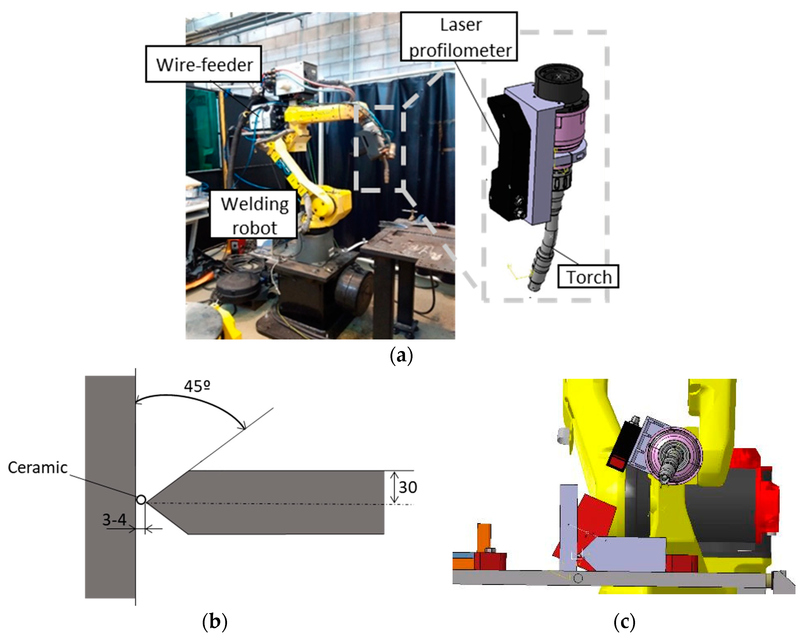
Figure 2.
(a) Data acquisition chain for the developed intelligent and adaptive welding system; (b) three-dimensional reconstruction of the acquired profiles; (c) discrete profile of the joint.
Figure 2.
(a) Data acquisition chain for the developed intelligent and adaptive welding system; (b) three-dimensional reconstruction of the acquired profiles; (c) discrete profile of the joint.
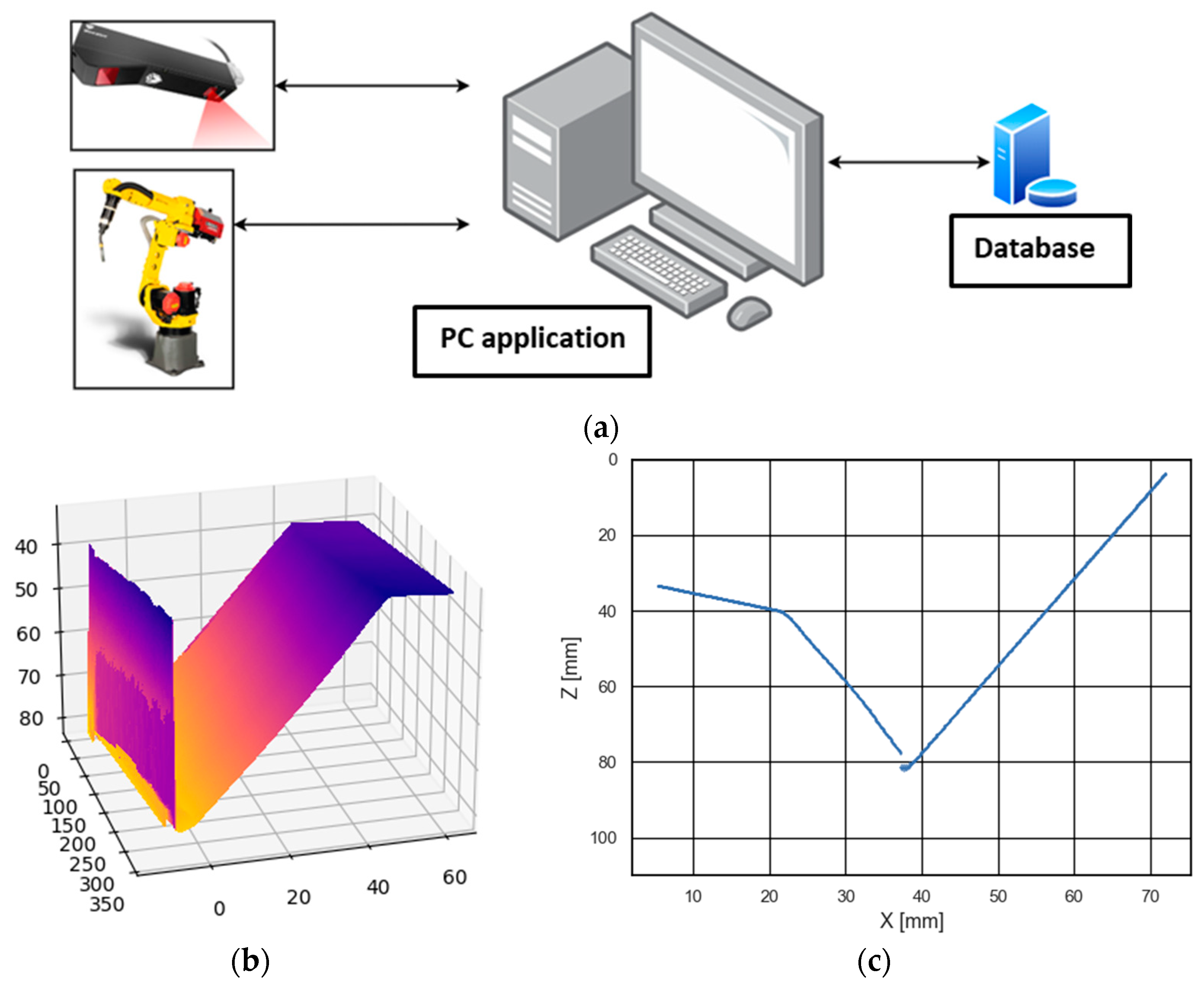
Figure 3.
(a) Profiles acquired after depositing the first bead with an oscillation amplitude of 0 mm and 3 mm; (b) Profiles acquired after depositing the first bead with a variation of the torch inclination angle of 0º and 3º; (c) Profiles acquired after depositing the first bead with a variation of the torch inclination angle of 0º and -3º.
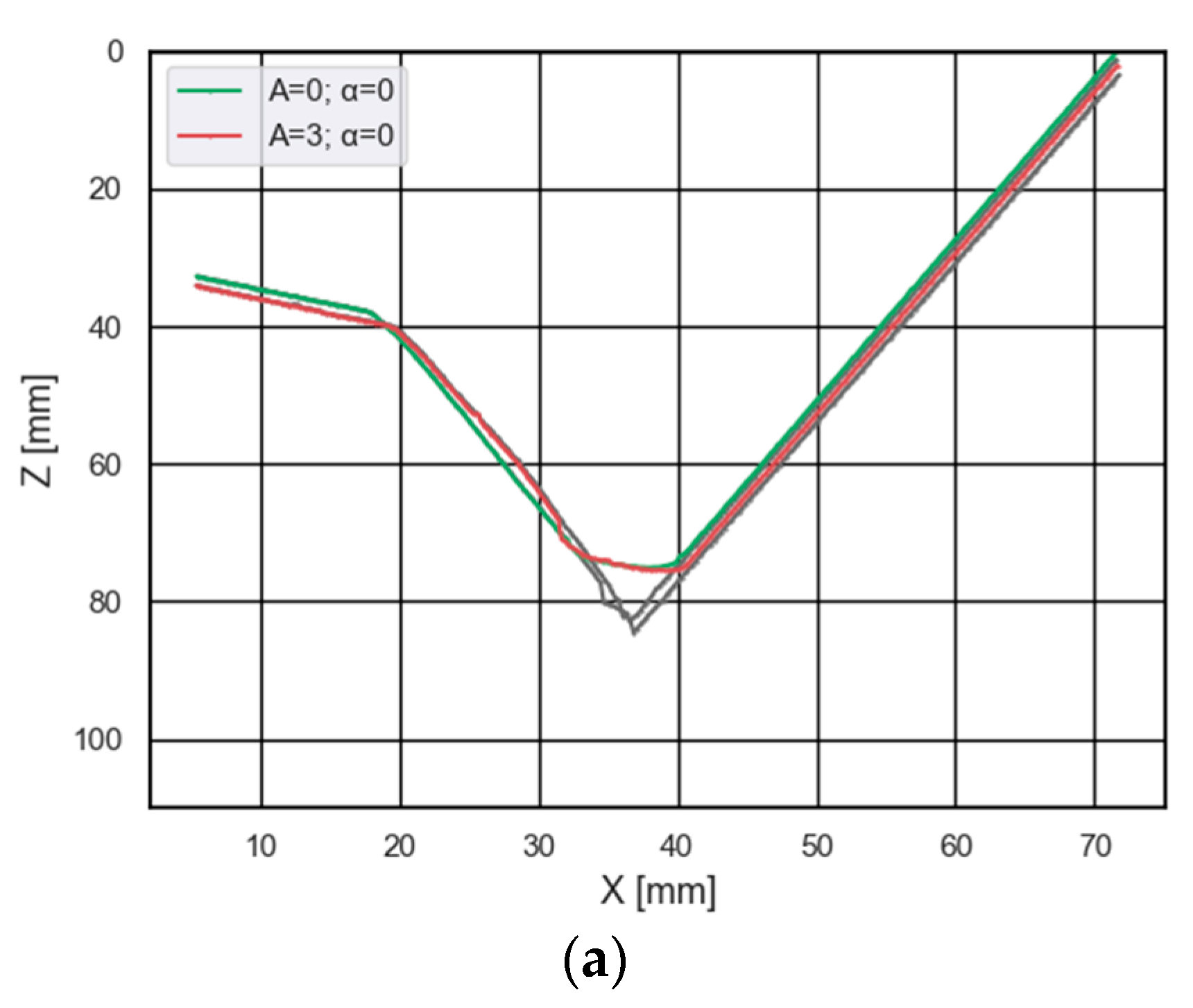
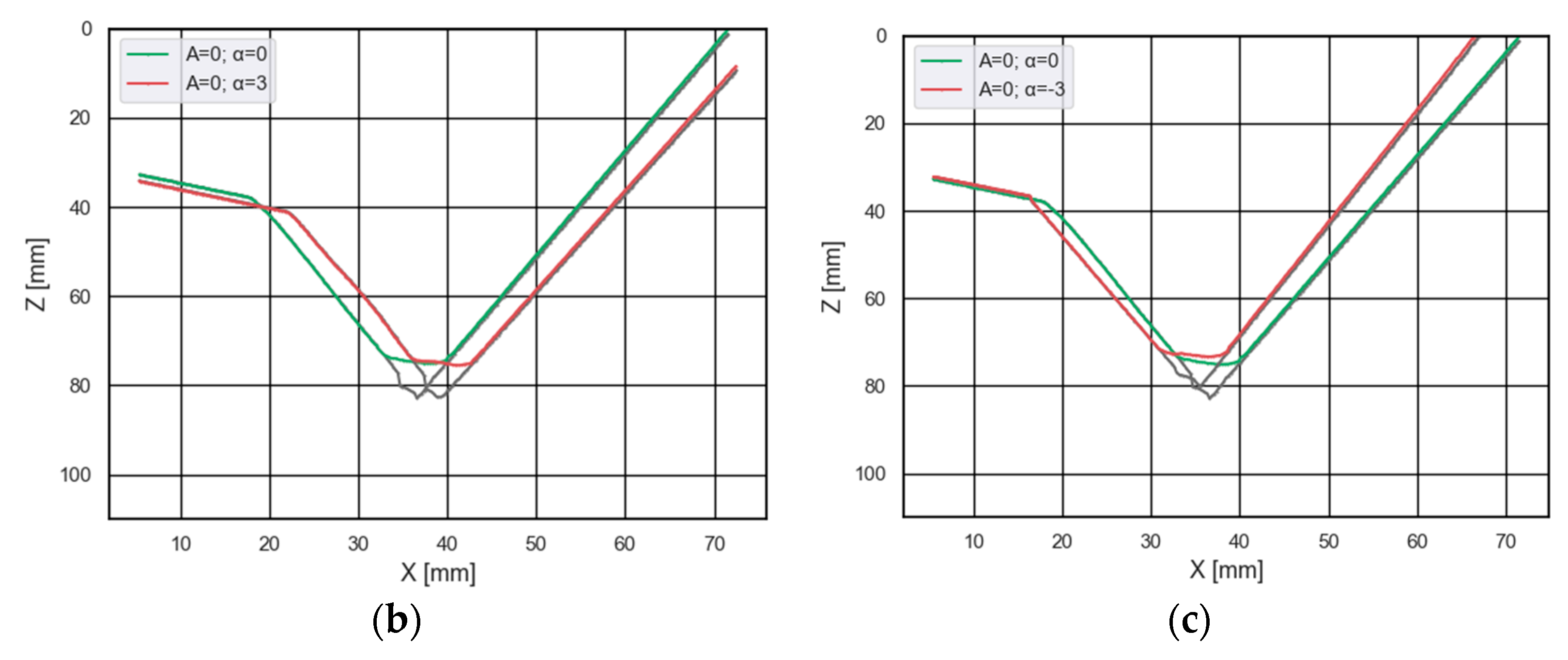
Figure 4.
Stage of processing the measured profile by the laser profilometer where the data is approximated to a polynomial of degree 15.
Figure 4.
Stage of processing the measured profile by the laser profilometer where the data is approximated to a polynomial of degree 15.
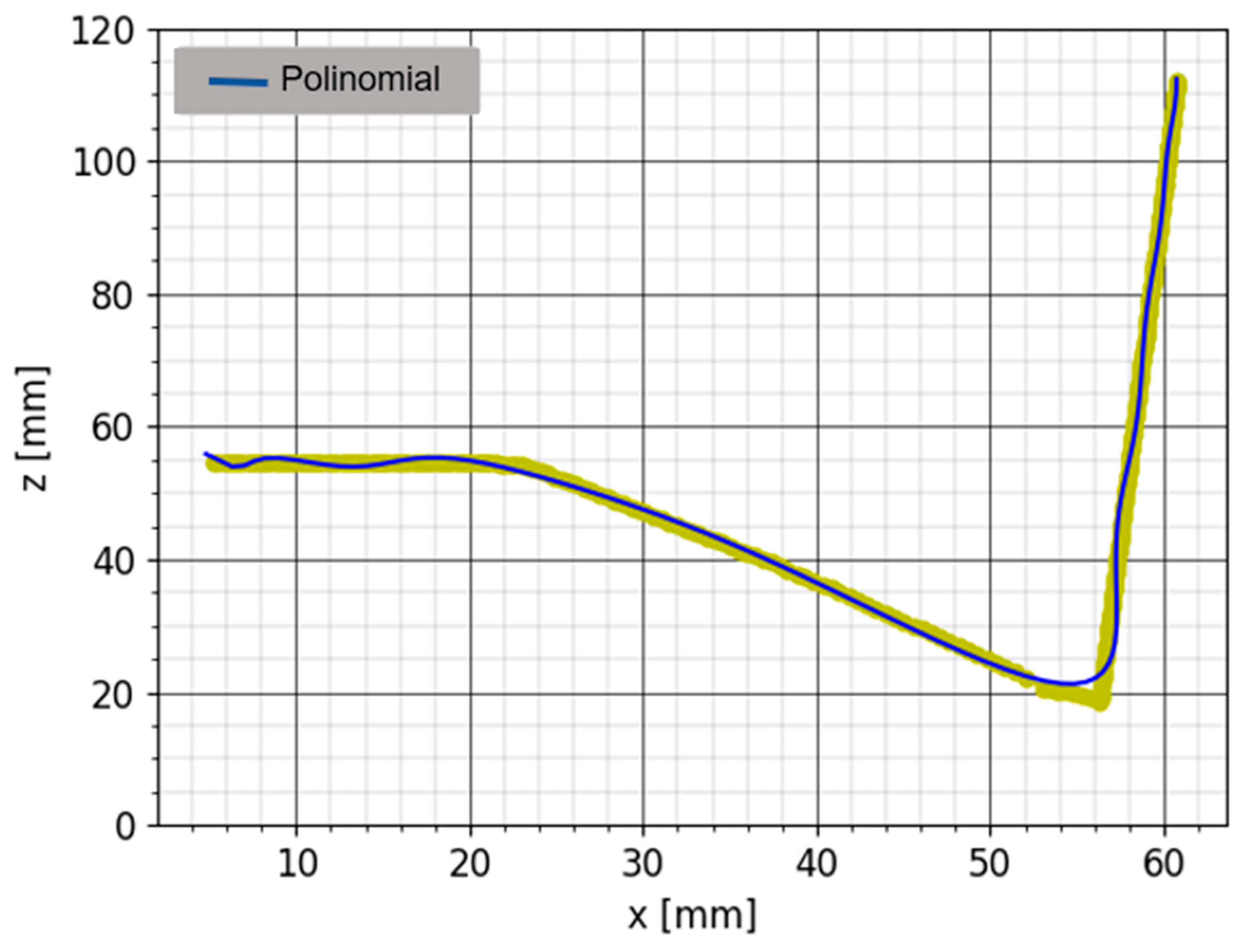
Figure 5.
Procedure for the selection of welding points.
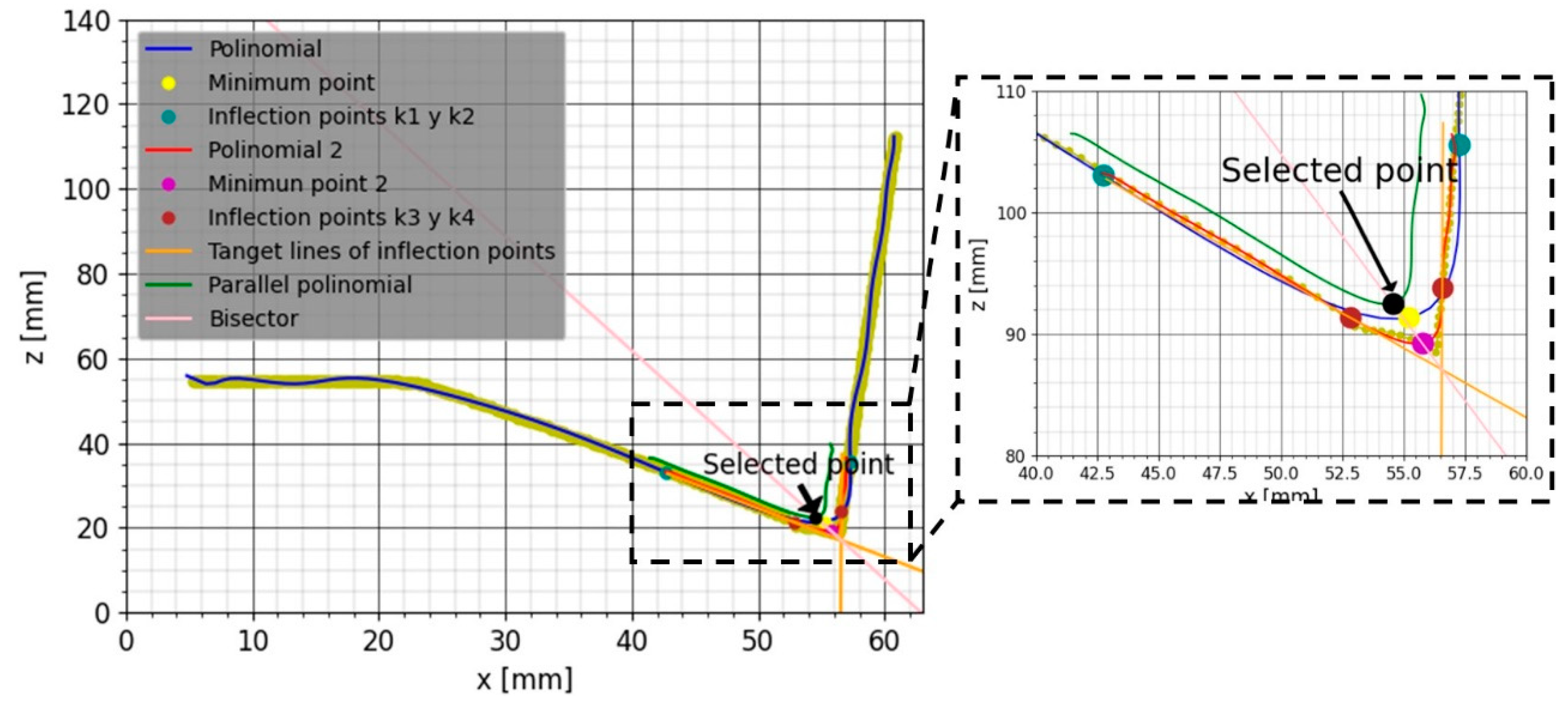
Figure 7.
Validation of the developed system: (a) Comparison of points selected by an expert operator and by the adaptive and intelligent system developed in this research; (b) Joint welded using the developed system.
Figure 7.
Validation of the developed system: (a) Comparison of points selected by an expert operator and by the adaptive and intelligent system developed in this research; (b) Joint welded using the developed system.
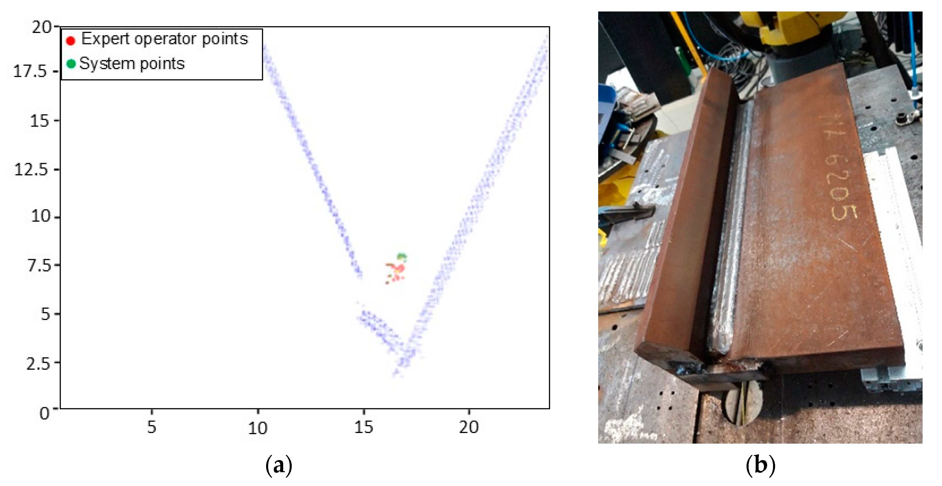

Table 1.
Variation of the most critical parameters of the welding process for the analysis of their influence.
Table 1.
Variation of the most critical parameters of the welding process for the analysis of their influence.
| Analyzed Parameter | Minimum Value | Maximum Value | Increment |
|---|---|---|---|
| Oscillation amplitude (A) | 0 mm | 3 mm | 1 mm |
| Angle variation (α) | -3º | 3º | 1º |
Disclaimer/Publisher’s Note: The statements, opinions and data contained in all publications are solely those of the individual author(s) and contributor(s) and not of MDPI and/or the editor(s). MDPI and/or the editor(s) disclaim responsibility for any injury to people or property resulting from any ideas, methods, instructions or products referred to in the content. |
© 2023 by the authors. Licensee MDPI, Basel, Switzerland. This article is an open access article distributed under the terms and conditions of the Creative Commons Attribution (CC BY) license (http://creativecommons.org/licenses/by/4.0/).
Copyright: This open access article is published under a Creative Commons CC BY 4.0 license, which permit the free download, distribution, and reuse, provided that the author and preprint are cited in any reuse.


