
Submitted:
16 August 2025
Posted:
18 August 2025
You are already at the latest version
Abstract
This paper presents the design and implementation of an inverse kinematics (IK) model for Arslan, a humanoid robot with a biomechanically realistic neck structure. The neck, modeled from 3D-scanned human cervical vertebrae, achieves natural flexion/extension and axial rotation through a two-motor system coupled with springs and elastic bands. The resulting mechanical compliance introduces non-linearities that make conventional analytical IK models ineffective. To address this, a stereo vision system with a laser reference was used to capture over 2,500 head pose samples across defined motor angle ranges. A Convolutional Neural Network (CNN) with Bayesian Regularization was trained to predict motor angles from the 3D direction of a sound source. Experimental results demonstrate high accuracy, with standard deviations of 0.45° for flexion/extension and 1.02° for rotation, and mean estimation errors of 1.96° and 3.96°, respectively. The proposed CNN-based IK model enables smooth, precise head orientation despite biomechanical flexibility, offering a robust approach for humanoid robots requiring realistic motion in response to sensory cues.
Keywords:
inverse kinematics
; Arslan humanoid robot
; stereo vision
; CNN
; sound source localization
1. Introduction
The Robotic Information System (RIS) is a novel information system design that uses intelligent robots to deliver data, information processing, and services to consumers across large geographic areas [1]. An abstract representation of the RIS shows three major pieces (Figure 1): database servers, the data and information processing engine (The-Oracle), and the head of a humanoid robot (Arslan). Each of those blocks was created with some enhancements to the current techniques that are typically employed to ensure prompt and effective response.
Figure 1.
Robotic Information System (RIS) main blocks [1].
Figure 1.
Robotic Information System (RIS) main blocks [1].
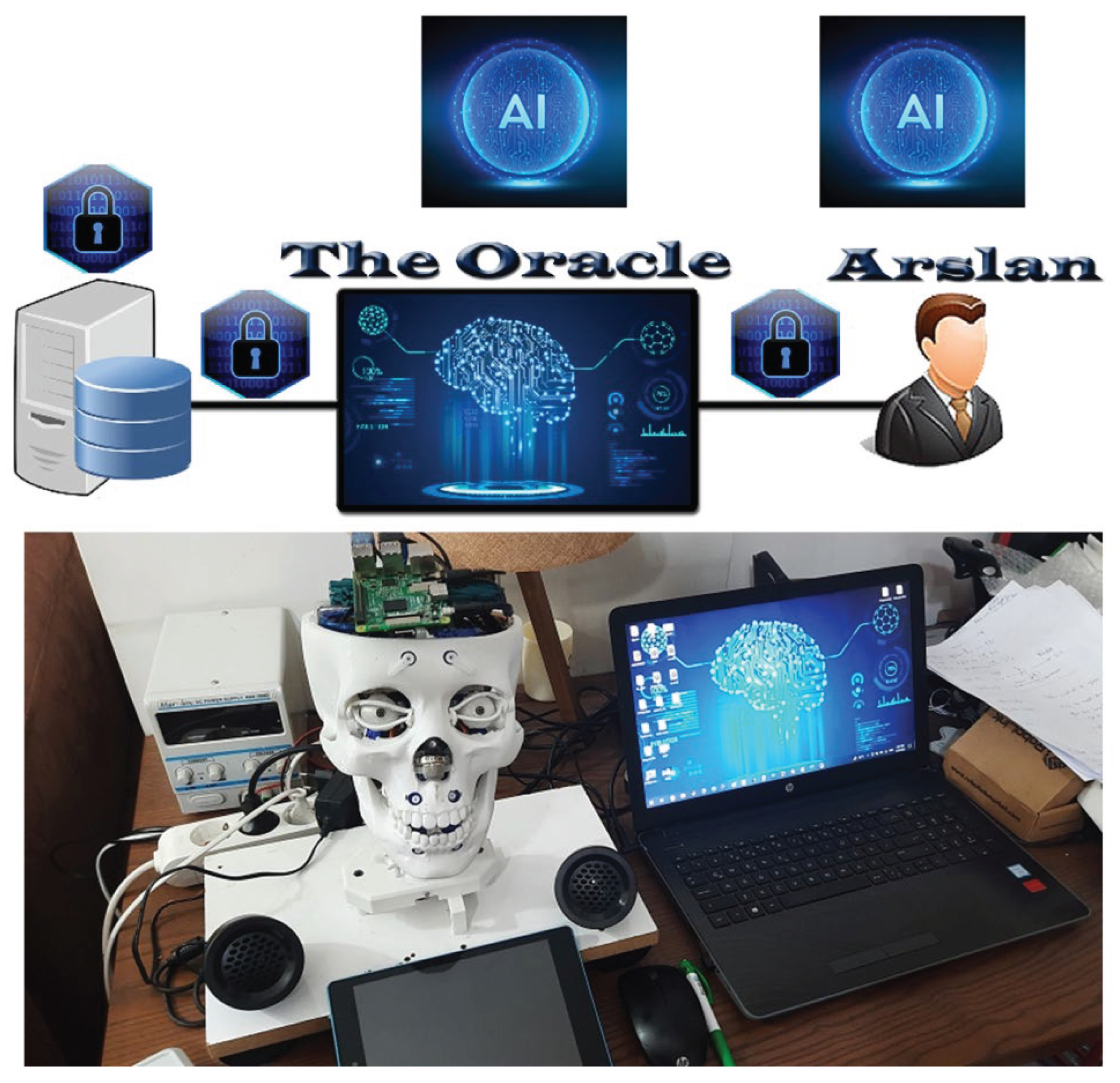
The primary front-end of the system is the Arslan humanoid robot, which has a 3D vision system [2], a 3D audition system [3], biomechanical systems for speaking and emotion, a smelling sensor, and an NLP system. Arslan itself contains a portion of the system’s AI, while The-Oracle contains the remainder.
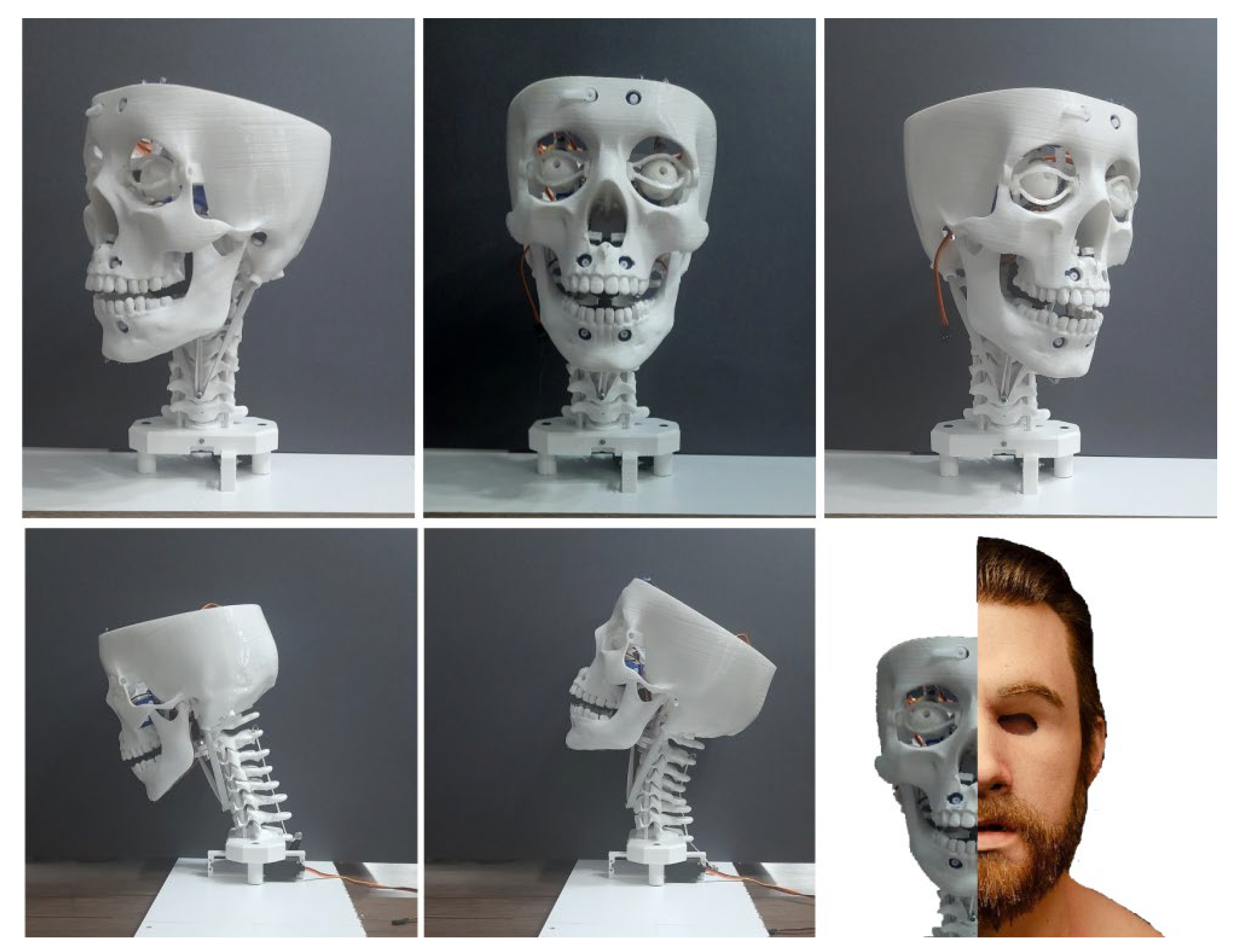
In order to achieve a realistic motion, Arslan’s nick was developed to resemble a human’s nick structure using 3D-scanned vertebrae [4]. Since previous humanoid robots have been designed to execute rotation motions independent of displacement action, they lack this biomechanical design.
Since humans rarely do it in everyday life, Arslan did not need to complete every motion to the highest rating. Only flexion/extension and axial rotation have been permitted because lateral bending has very little bearing on Arslan’s application scope.
In a practical application, the Inverse Kinematics Model is necessary when Arslan detects a sound source and wishes to tilt its head in that direction. In order to achieve smooth motion of Arslan’s head, this study applies a motion dynamics model and uses CNN to predict those angles.
2. Methods
2.1. Arslan’s Nick Biomechanics
Axial rotation is permitted for C1-C2 because it has the biggest influence on axial rotation and to avoid conflict between flexion/extension motion and axial rotation at that level. Flexion/extension has been designed to be included in all levels from C2 to T1. Arslan’s cervical joints have been connected with springs and elastic bands, and two servo motors—one for flexion/extension motion and the other for axial rotation—have been used to control Arslan’s movement. Because of the realistic form of the nick, the head has been changed during flexion and extension, just like a human, and Arslan’s nick mechanism permits one side axial rotation of 41° and flexion/extension of 45°, giving it an appropriate range of motion (Figure 2).
Figure 2.
Arslan’s Physical Structure and nick rotations [1].
Figure 2.
Arslan’s Physical Structure and nick rotations [1].
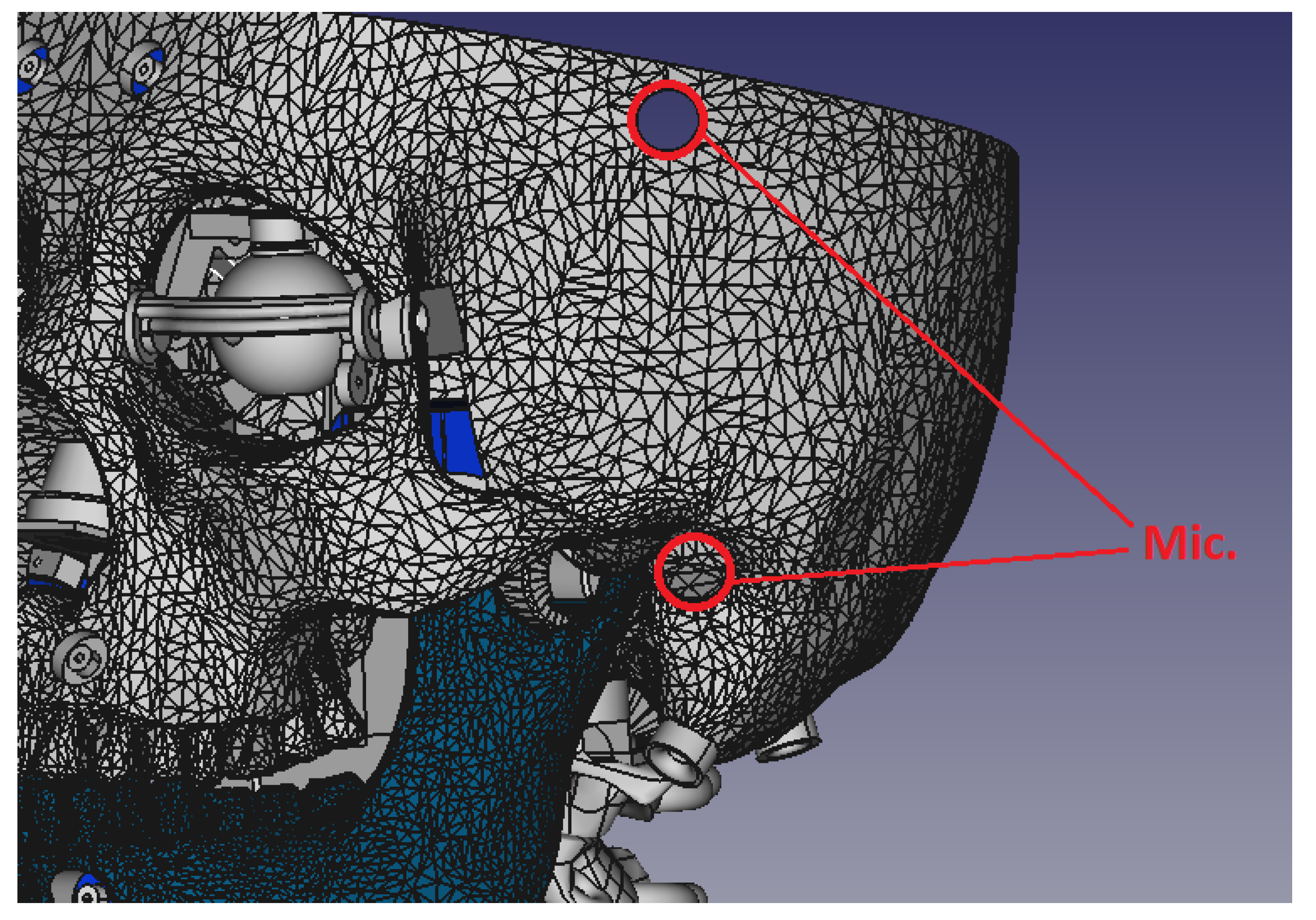
2.2. Arslan’s Audition System
A computational model for sound source localization in 2D for the Arslan humanoid robot audition system using artificial neural networks has been introduced by Al Karaki [3]. Using two microphones, the system’s design aids in sound source angle prediction. The positive results confirm the effectiveness of the system’s approach and its feasibility for real-world use. Four microphones will be utilized in Arslan to pinpoint the sound source in three dimensions, and this two-dimensional model will be enhanced to incorporate the sound direction from two angles. Two microphones are situated in the ear canal, while the other two are situated on the forehead’s sides (Figure 3). A fifth microphone for Arslan’s speech audition is situated at its nose; it should be mentioned that those microphones are simply used to measure sound intensity.
Figure 3.
Places of the microphones which are used in Sound source localization in Arslan humanoid robot.
Figure 3.
Places of the microphones which are used in Sound source localization in Arslan humanoid robot.
2.3. Invers Kinematics Model Using Stereo Vision and CNN
Arslan’s nick is made up of seven joints that are held together by elastic bands and a spring, which prevents the joints from moving rigidly. Since only two motors control those joints, it is very challenging to determine the location and orientation of each joint because it depends on the motor angles, spring characteristics, spring tension, elastic band tension, the joints before and after it, and the momentum of various system components.
Arslan has a laser LED mounted on his nose that emits a beam that symbolizes the visual vector. As a reference, the laser spot location in 3D is transferred to a virtual location at the middle of the Arslan’s skull using a stereo vision system [5]. The real world angles (Theta and Phi) are computed by mapping vision vectors from the reference point to the laser spot at each setting over a range of angles applied to the flexion/extension motor (Th1 = 75 to 109 step 2) and head rotation (Th2 = 5 to 45 step 2). More than 2500 samples are produced by repeating this scanning process six times. Since the laser was invisible to the two cameras, some samples were omitted, making it impossible to determine the 3D location. To recover motor angles from speech source direction, a CNN with two hidden layers of 35 and 15 is employed, along with a training approach that uses Bayesian Regularization for 5000 epochs.
3. Results
The laser spot’s 3D placement at each motor’s angle pair is extremely near, despite the nick’s flexibility (Table 1). Given that the computed flexion/extension and head rotation angles had typical standard deviations of 0.45 and 1.02 degrees, respectively, sample scanning error can be disregarded (Table 2).

Table 1.
Samples of data scanning results.
| Motors Angles | Source Angles | ||
|---|---|---|---|
| Theta1 | Theta2 | Phi | Theta |
| 75 | 5 | 76.13194 | 39.43156 |
| 75 | 7 | 75.93287 | 37.72342 |
| 75 | 9 | 77.54064 | 28.87504 |
| 75 | 11 | 78.12524 | 24.50305 |
| 75 | 13 | 78.55238 | 20.84372 |
| 75 | 15 | 78.92509 | 17.26678 |
| 75 | 17 | 79.2618 | 12.79393 |
| 75 | 19 | 79.53727 | 7.791852 |
| 75 | 21 | 79.76449 | 3.746861 |
| 75 | 23 | 80.09461 | -2.45265 |
| 75 | 25 | 80.45018 | -7.91286 |
| 75 | 27 | 80.5474 | -13.9682 |
| 75 | 29 | 80.5205 | -19.9437 |
| 75 | 31 | 80.36305 | -25.3383 |
| 75 | 33 | 80.16096 | -30.7363 |
Table 2.
Samples of data statistics.
| Motors Angles | Source Angles | ||||||
|---|---|---|---|---|---|---|---|
| Theta1 | Theta2 | Phi | Th | AVG Phi | STD | AVG Th | STD |
| 75 | 15 | 78.93 | 17.27 | 78.23 | ±0.39 | 16.05 | ±0.74 |
| 78.36 | 16.44 | ||||||
| 78.03 | 15.50 | ||||||
| 78.05 | 15.72 | ||||||
| 78.23 | 16.11 | ||||||
| 77.80 | 15.24 | ||||||
| 75 | 17 | 79.26 | 12.79 | 78.59 | ±0.38 | 11.73 | ±0.59 |
| 78.72 | 11.96 | ||||||
| 78.40 | 11.37 | ||||||
| 78.42 | 11.52 | ||||||
| 78.59 | 11.64 | ||||||
| 78.17 | 11.13 | ||||||
| 75 | 19 | 79.54 | 7.79 | 78.92 | ±0.35 | 6.85 | ±0.55 |
| 79.06 | 7.02 | ||||||
| 78.71 | 6.65 | ||||||
| 78.76 | 6.67 | ||||||
| 78.91 | 6.86 | ||||||
| 78.52 | 6.12 | ||||||
The CNN interprets motor angles as the network’s outputs and source angle values as the network’s inputs. To get better outcomes, inputs and outputs were standardized prior to training. The actual and anticipated outputs match well, according to the training results (Figure 4).
Figure 4.
Training Results.
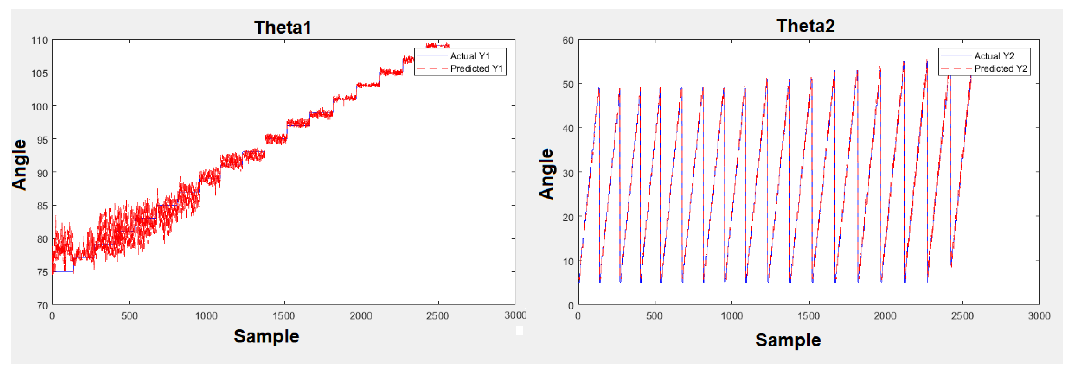
The average of the source angles is tested as the network’s input, and the output findings are compared to the angles of the associated motors for final verification. Theta1 and Theta2 have respective estimation errors of 1.96 (±4.46) and 3.96 (±1.88) for the average angles.
4. Conclusions
The inverse kinematics model developed for Arslan successfully integrates stereo vision data and CNN-based prediction to overcome the challenges posed by a biomechanically flexible neck structure. By replacing complex analytical calculations with a data-driven approach, the system reliably maps sound source directions to motor commands, achieving low estimation errors and smooth motion. The results validate the effectiveness of using deep learning for IK in robots with non-rigid biomechanics. This approach can be extended to other humanoid platforms where mechanical compliance and sensory integration are required. Future work will enhance the auditory system to full 3D localization, expand the dataset for more motion ranges, and investigate real-time performance in dynamic environments.
References
- Elaff, “Robotic Information System (RIS): Design of Humanoid Robot’s Head Based on Human Biomechanics”, El-Cezeri Journal of Science and Engineering, vol. 10, no. 2, pp. 420–432, 2023. [CrossRef]
- E. Guemmam and I. Elaff, “Human Face Localization in 3D For Humanoid Robot Vision,” 2025 7th International Congress on Human-Computer Interaction, Optimization and Robotic Applications (ICHORA), Ankara, Turkiye, 2025, pp. 1-4. [CrossRef]
- M. I. Al Karaki and I. Elaff, “Modelling Humanoid Robot Audition for Sound Source Localization Using Artifical Neural Network,” 2025 7th International Congress on Human-Computer Interaction, Optimization and Robotic Applications (ICHORA), Ankara, Turkiye, 2025, pp. 1-4. [CrossRef]
- A.A. White I11 and M.M. Panjabi. Clinical Biomechanics of the Spine. J.B. Lippincott Company, Philadelphia, Toronto, 2nd edition, 1990.
- Perez, H.; Tah, J.H.M.”Towards Automated Measurement of As-Built Components Using Computer Vision.” Sensors 2023, 23:7110. [CrossRef]
Disclaimer/Publisher’s Note: The statements, opinions and data contained in all publications are solely those of the individual author(s) and contributor(s) and not of MDPI and/or the editor(s). MDPI and/or the editor(s) disclaim responsibility for any injury to people or property resulting from any ideas, methods, instructions or products referred to in the content. |
© 2025 by the authors. Licensee MDPI, Basel, Switzerland. This article is an open access article distributed under the terms and conditions of the Creative Commons Attribution (CC BY) license (http://creativecommons.org/licenses/by/4.0/).
Copyright: This open access article is published under a Creative Commons CC BY 4.0 license, which permit the free download, distribution, and reuse, provided that the author and preprint are cited in any reuse.


