Submitted:
15 August 2025
Posted:
18 August 2025
You are already at the latest version
Abstract
Carbon fibre-reinforced composites are being more and more used since several years. In the same time the need for adequate methods to recycle fibres from industrial or post-industrial waste is rising. This paper investigates the state-of-the-art methodol-ogies for processing recycled Carbon Fibres (rCF) into reinforcement textiles, identifies key challenges, and presents novel production techniques aimed at optimizing their integration into textile structures for composites. Different processing methods are an-alysed and their impact on the mechanical properties of the composites is investigated on coupon level.
Keywords:
recycled carbon fibres
; non-crimp fabrics
; composite production
1. Introduction
The global push towards sustainable manufacturing practices has placed significant emphasis on recycling and reusing carbon fibre-reinforced polymers (CFRPs). Reclaiming carbon fibres from end-of life parts is feasible on different pathways. [1] Independently from the reclamation pathway, such as pyrolysis, solvolysis or the use of post-industrial dry fibres, average fibre length is extremely reduced compared to continuous virgin fibres. Besides this, the embodied energy during the production of carbon fibres is high due to high process temperatures and long process cycles. When recovering and re-using the fibres, the sustainability of the product is increased. [2,3] In consequence, the textile production methods need to be adapted to the fibres and pre-processing steps are required. Therefore, developing viable (pre-) processing routes for rCF is essential to address key limitations such as fibre length variability, textile compaction and the fibre volume fraction (FVF) in the final composite. The processability of textiles into composites with a determined FVF is crucial for the use of rCF-textiles in industrial applications.
In this study the latest advancements in the processing of rCF into tapes into Non-Crimp Fabrics and finally into composites is investigated. The implications of the composite manufacturing method onto the mechanical properties are evaluated.
2. State of the Art
The use of carbon fibres as reinforcement fibres for composites has been investigated for many decades. With an increasing awareness and demand for more sustainable solutions, the interest in the recovery and re-use of the fibres has been rising as well. Different waste streams are generated along the process chain. Starting with cut-off fibres during the production of textiles or the preform production, secondly, waste parts and fibres are generated during the part production and at least parts after the use at the end-of-life stage. Recycling methods for CFRP are widely being investigated. Here, thermal and chemical methods have been highly investigated in the past years [4]. Especially, the reclaiming using pyrolysis has reached a technology readiness level (TRL) of 9, while the TRL of microwave and fluidized bed pyrolysis range between 4 and 6. Fibres reclaimed using pyrolysis are already available commercially from different companies. As chemical method the solvolysis is under development. The TRL is at 5 to 6 and commercially available fibres are slowly entering the market. The TRL of mechanical recycling of CF is at 6 to 7 but is partially seen as pre-step prior to the before mentioned processes. [5]
In general, reclaimed and recycled fibres are available as staple fibres. Fibre lengths between 2 mm and 100 mm are common. Thus, different pre-processing methods are required. The fibre sizing is the second point which is a difference between virgin and recycled carbon fibres. Usually, surfaces of recycled fibre from solvolysis and pyrolysis are free of sizing and the renewal of the sizing on short fibres is being investigated. [6,7,8] The sizing is required to allow a suiting fibre-matrix adhesion. Additionally, inconsistencies in surface treatments can impact adhesion within resin matrices, leading to weak bonding. The bulkiness and the surface of rCF-based semi-finished products complicates handling and compaction during processing. Another major limitation is the lack of fibre orientation, which reduces the predictability and uniformity of mechanical properties. Overcoming these challenges requires innovations in fibre processing and preform design.
The development of technical textiles from rCF has been investigated using different approaches. Besides nonwovens with included matrix fibres, the production of rCF yarns has been highly investigated. Out of these yarns woven and NCF can be produced. [9,10,11] The yarn spinning process is highly complex and in consequence the production cost rise. The standard dry nonwoven production process is investigated in detail by [12,13,14]. Here, fibre orientation can be adjusted partially in machine direction and cross-machine direction. Similar to the referred work, a standard carding machine is used in this study. Besides that, also water-based processes are investigated by several researchers and companies. [15,16,17,18]
The production of thermoplastic composites reinforced with rCF has been investigated. Mostly, organosheets from nonwovens or textiles made of hybrid yarns are investigated. [19,20,21] In recent works, the focus was on thermoplastic matrices. In early works also thermoset matrices were investigated. In general, the focus is on the achievable mechanical properties and fibre volume fractions are often not reported. For thermoplastic composites, the matrix system is usually added during the textile production process or during yarn production. Then, FVF of up to 70 % can be achieved [9]. The compression of the textiles or parts after passing the glass transition temperature of the matrix component is crucial, to compact the part and achieve thin parts with high FVF. The FVF is highly related to the used production method. In general, it is shown that using thermoset matrices results in rather low FVF of rCFRP. There are several possible causes for this:
- Low compressibility of textiles
- High percentages of ancillary fibres
- Missing fibre orientation.
In literature, only one reference was found where the production methods for rCFRP parts were investigated to achieve FVF of higher than 25 %. [22] report that a FVF of up to 41 % was achieved for unidirectional composites made of rCF yarns wrapped around a wrapping frame. In this paper, two different production methods for the production of composites made of rCF-tape-NCF are investigated. A commonly used vacuum infusion is compared with a hand-layup compression moulding. The used materials and methods will be presented in the following sections. It is reported from the industry, that prepreg nonwoven materials can also achieve FVF of up to 30 %. Therefore, the goal of this study is to investigate an adapted composite production method for semi-finished parts made of rCF. This is one crucial step to enable the use of rCF in semi-structural parts with high quality surfaces.
3. Materials and Methods
3.1. Materials
Slivers produced from rCF/CoPA fibres are investigated. The slivers are produced at the Institut für Textiltechnik Augsburg gGmbH, Augsburg (GER). The slivers are composed of 95 w.-% T700S fibres from Toray Composite Materials America Inc., Tacoma (WA, USA) from cut off wastes of fabric production and 5 w.-% Co-Polyamid (CoPA) of type Grillon® KA 140 from EMS Chemie AG, Domat/Ems (CH). [23,24] Different thermoplastic fibres were investigated in preliminary studies. It was found, that CoPA fibres of the suggested type are most relevant in the given percentage of 5 w.-%. The average carbon fibre length amounts to 70 ± 2 mm in average as incoming material. It is assumed that the mechanical properties of the single fibres are not reduced compared to virgin continuous single fibres. The minimum fibre staple length of KA 140 fibres amounts to 51 mm [23]. Here, cut-off wastes are used to provide a proof of concept for the suggested production route and due to the availability of the fibres. As resin system for composite production an Epoxy resin type EPIKOTE RESIN MGS RIMR426 and a hardener type RIM H435 (pot life of 120 min) produced by Westlake Corporation, Houston, Texas (USA) with a mixing ratio of 100:26 w.-% are used.
3.2. Methods
Sliver Production
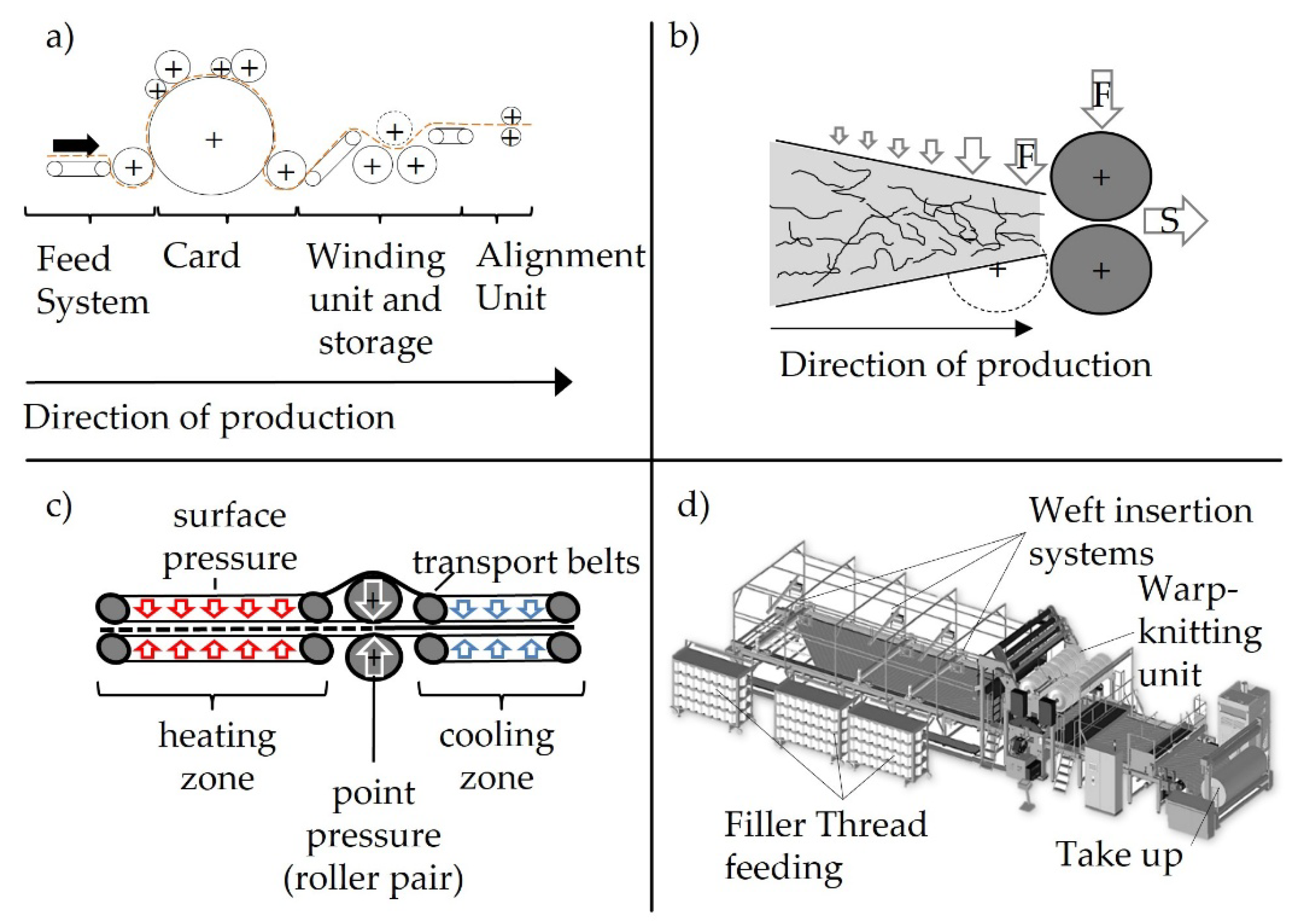
The fibre materials are mixed and oriented using an industrial carding line KC11 2-4 SD / MEK 11 from Dilo Systems GmbH, Eberbach (GER). The full process flow from fibre to nonwoven to the final sliver is shown in Figure 2. From the bale opener, the fibres are mixed and further opened using a picker. For the fine opening a dosing opener is used and the material is further processed to a chute feed. The areal weight of the produced nonwoven is adjusted using a belt scale. In the following, the mixed fibres are transported to the carding machine to align the fibres and to create a uniform web (see Figure 1).
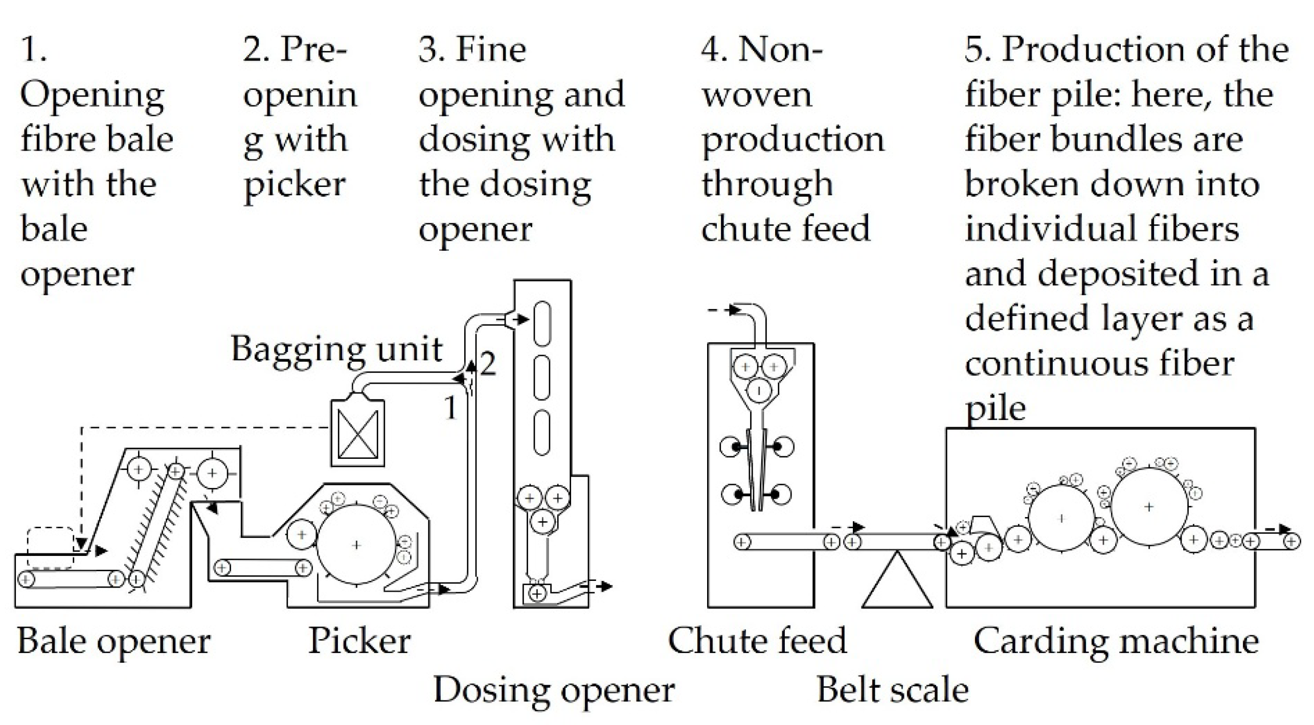
Prior to the alignment unit, a winding and storage unit is passed by the web (see Figure 2). In preliminary works, different areal weights were tested that range between 1 gsm and 15 gsm. [27] Also, the alignment processes were adapted and investigated. [28] From these studies, optimized tape production parameters are chosen and are presented in [28] and [12]. A homogeneous fibre distribution is achieved by mixing and carding, followed by tape production and fixation for improved fibre alignment. The average sliver width was measured using an optical sensor type optoCONTROL 2520 from MICRO-EPSILON Eltrotec GmbH, Göppingen (GER). Non-crimp fabric production was performed to enhance the mechanical performance of the composite.
NCF Production
The produced and measured tapes are further processed using a multi-axial warp knitting machine, Copcentra MAX 3 CNC from LIBA Maschinenfabrik GmbH, Naila today owned by KARL MAYER Holding SE & Co. KG, Obertshausen (GER). Firstly, a supporting grid is produced using the weft insert systems. Based on this polyester yarn grid, the rCF-tapes are placed manually in a 90° angle. Consequently, the fibre orientation is oriented at a 90° angle relative to the production direction. The grid was produced in +/- 45° using polyester yarns with a yarn count of 25 tex and a thread density of 0,5 F/cm. An overlapping of 2-3 mm is aimed. The layup is warp-knitted using a 2 mm fringe stitching with 8,3 tex polyester warping yarns and an E6 needle gauge. The areal weight of the stitiching thread amounts to 7,7 g/m².
Characterisation
The cover factor of the produced textiles is determined using an LED-Inspection-Table built and developed at the Institut für Textiltechnik (ITA) of RWTH Aachen University [30]. The cover factor is a parameter to describe the quality and homogeneity of the textiles. The used set-up is shown in Figure 3. The test stand comprises an illuminated table, a height-adjustable camera system and a measuring computer with specially programmed software for image analysis. The colours of the light of the translucent table can be adapted. Initially, a greyscale image of the textiles is captured and subsequently converted into a binary image. The cover factor, or the coverage value of the black pixels in relation to the total number of pixels, is determined in the binary image. Black pixels are indicative of closed areas, while white pixels represent empty spaces or stripes. The cover factor is reported as percentage of black pixels in relation to the total amount of pixels. A reference is shown in Figure 4. Here, needle punctures, gaps between as well as thin spots within the slivers are visible as white spots. The shown sample amounts to a cover factor of 97,5 % in average.
With this testing method a fast and qualitative evaluation of the textile quality is enabled. Fibre orientation measurements are mostly only measuring the fibre orientation on the surface. Due to the thickness of the tapes this value would not be reliable. Thus, the cover factor is used as evaluation factor.
Composite Production
For the preparation of the reference composite parts, a vacuum infusion process is used. The production was performed according to the description in [31]. Overall, three plates are produced and investigated. An overview of the samples and used processes is given in Table 1. All samples consist of three layers of textile with the same fibre orientation. All fibres are oriented in 90° compared to the direction of production. Thus, tests are performed in fibre direction. The areal weights of all layers were determined by measuring the weight of the prepared textiles for the composite production.
As second method, a hand-layup in a fixed cavity is used. Therefore, a solid cavity consisting of two aluminium plates (450 mm × 320 mm × 20 mm) and a stainless-steel frame (450 mm × 320 mm × 2 mm) with a central cut-out (350 mm × 220 mm) are built. The aluminium plates enclose the cavity in which the textile layup is placed, ensuring a controlled moulding environment. To meet the requirements of the standard for testing the tensile properties of the resulting composites, DIN EN ISO 527-5, the cavity thickness is set to 2 ± 0.2 mm. A hand-layup process is employed to impregnate the textile, ensuring complete fibre wetting and minimizing void formation. For precise alignment, two M10 threaded rods (25 mm) are used. The lower aluminium plate features two M10 threaded holes, while the stainless-steel sheet and upper plate have 10 mm through-holes, allowing accurate centring. The absence of threads in the upper components enables easy demoulding. To aid separation after the lamination, four additional M10 threaded holes in the lower plate accommodate screws that apply controlled pressure for disassembly. Stainless steel was chosen as the intermediate layer to prevent mechanical damage during demoulding. (see Figure 5)
The textiles are placed between the two sides of the mould. The required amount of resin is calculated depending on the weight and the compressibility of the textile. Prior to the lamination, a proper closure of the mould is ensured. The resin is distributed over the textiles. The stack of textile and resin is placed in the mould. The edges of the cavity are cleaned from outstanding fibres and the mould is closed. The cavity is set in a press type LZT 30-HT from Langzauner Gesellschaft m. b. H., Lambrechten (AUS) covered with a vacuum bag to avoid leakage. The press is closed for 24 h under 250 kN clamping force. This amounts to a pressure on the final part of 3,25 bar. No heat is applied during the curing cycle. After de-moulding, all plates are tempered and prepared for testing.

Table 2.
Processing parameters.
| Parameter | Vacuum infusion | Compression moulding |
| Temperature | Ambient temperature | Ambient temperature |
| Pressure | Vacuum of 0,5-2,5 mbar | 3,25 bar |
| Additional layers | Release film, breather cloth, peel ply, vacuum bag |
Release film |
| Duration | 24 h | 24 h |
| Post-curing cycle | 80 °C, 1 bar | 80 °C, 1 bar |
Composite Testing
As testing methods of the final composites, tensile tests according to DIN EN ISO 574-4 and bending tests according to DIN EN ISO 14125 are performed in fibre direction [32,33]. The termination criteria were kept stable for all samples. Bending tests were terminated at a cut-off threshold of 70 % of the maximum measured force. The elongation was measured using a video extensometer. All tests are carried out in fibre direction. Failure modes are defined for alle tested samples. Eight samples are tested per plate. The FVF is calculated gravimetrically. To enable comparable results, all tensile strength results are normalized to a FVF of 30 %. The results show linear relation between elongation and tension. Thus, the law of mixtures can be applied.
3. Results
In total, one reference plate was produced using a vacuum infusion and two compression moulded plates were produced according to the described method. All results are shown in Table 3. During the compression moulding, minor dry spots have occurred on the surface of plate B6 (see Figure 6). The resulting plates can still be used for the composite testing, since a full impregnation of the centre is ensured by the resin distribution. Nevertheless, plate B3 is produced to ensure, that the results are not impacted by the dry spots.
Previous experimental studies demonstrated that compaction methods significantly impact rCF-based composite properties. Key findings indicate that thermal pressing methods achieved FVF of up to 31 %, improving tensile strength and modulus while maintaining material integrity. Tensile testing results revealed that optimized processing resulted in strength values competitive with traditional CFRPs, showcasing the potential of rCF-based materials in high-performance applications. The relationship between compaction force and material thickness was analysed in a separated study. The investigation is not part of this study and will be published separately. In the following the achieved mechanical properties are presented and discussed.
The width of the used slivers ranges between 27 mm and 33 mm in average. The measurements of the slivers used in the reference show the highest standard deviation of 5,19 mm while the lowest standard deviation of 3,87 mm is measured for the slivers used in B6. Using these slivers, textiles with areal weights of 230 to 260 gsm are produced with a determined area. The cover factors of all used textiles are similar and average between 96,37 % and 97,37 %. Standard woven fabrics range between 91 and 99 %. [34] Cover factors are usually not determined for multi-axial NCFs. Due to different angles of fibres the cover factor is expected to be at 100 %. Therefore, woven fabrics are used as reference factors. [34]
The tensile testing and bending results for all samples are shown in Table 4. For the compression moulded parts FVF of 27 % and 26 % are achieved. The FVF of the reference amounts to 17 %. Normalized tensile strength of the samples range between 549 MPa and 581 MPa. Here, the results are comparable between the reference and sample B3 and B6. When comparing the original results without normalisation, the average tensile strength for the compression moulding range between 523 MPa for sample B6 and 584 MPa for B3. Compared to that, the reference tensile strength is at 312 MPa. For all samples the elongation at break ranges between 1,26 % and 1,32 %. The average tensile moduli range between 22 GPa and 39 GPa. The samples B6 and B3 are at a similar level with 39 GPa and 38 GPa. The modulus of the reference sample amounts to 22 GPa.
Figure 7.
Tensile testing results of B3, B6 and the reference.
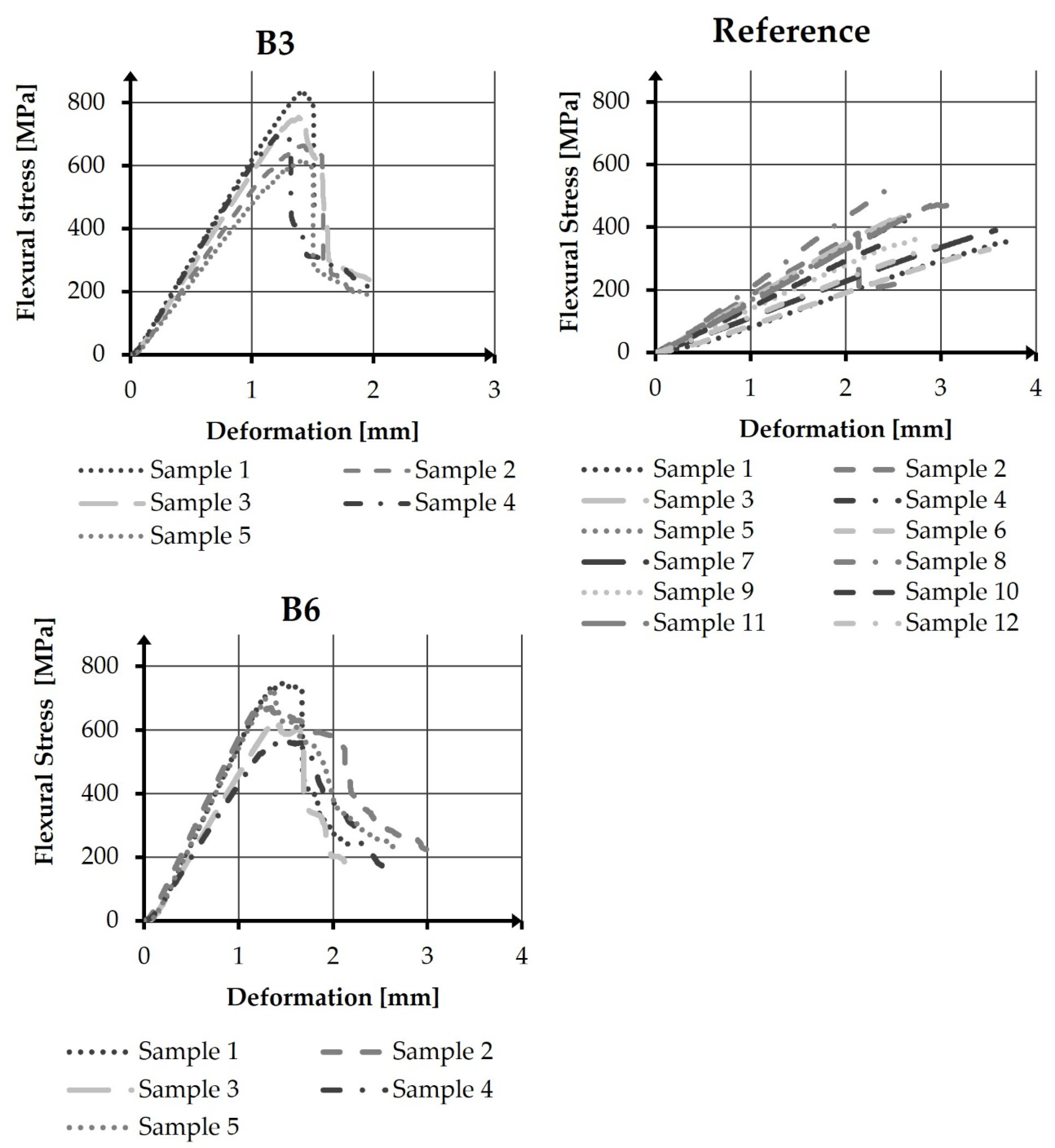
Table 5.
Bending Testing Results.
| No. | Number of Samples | Av. Width [mm] | Av. Thickness [mm] | Length [mm] | FVF [%] | Flexural Stress [MPa] | Flexural Modulus [GPa] | Elongation at Fmax [%] | |
| B6 | 5 | 15,03 | 1,51 | 30 | 27 | 667 ± 77 | 25 ± 11 | 1,30 ± 0,05 | |
| B3 | 5 | 14,99 | 1,52 | 30 | 26 | 712 ± 85 | 41 ± 15 | 1,26 ± 0,07 | |
| R | 12 | 14,96 | 2,43 | 48 | 17 | 400 ± 58 | 17 ± 6 | 1,32 ± 0,06 |
The flexural properties of the tested samples differ widely (see Table 5). The average maximum flexural strength of sample B6 amounts to 667 MPa with an average flexural modulus of 25 GPa. The results of sample B3 amount to 712 MPa in strength and to 41 GPa in modulus. In comparison to that the testing results of the reference samples are 400 MPa in average flexural stress and 17 GPa of average flexural modulus. Specimen of samples B3 and B6 show similar failure curves while the specimen of the reference show linear failure curves (see Figure 8). The failure curves of different specimen within the samples are consistent with one exemption for specimen 2 of the reference sample. Due to a higher thickness, the dimensions of the reference samples were adapted. According to the standard, the samples were cut to a width of 15 mm and a length of 48 mm.
The fracture surface analysis of the three series (B3, B6, and Reference) reveal distinct failure behaviours. Series B3 showed the highest mechanical performance, particularly in sample 1 with a clear fracture and layer splitting. Several samples of B3 failed in regions containing warp threads. In contrast, none of the B6 samples exhibited a failure where the samples were fully destroyed. Here, horizontal cracks, often near warp threads, dominated. The fracture patterns of B3 and B6 exhibited mostly minor fractures and crack progression was barely visible (see Figure 9). The reference series showed the highest number of total fractures, with several samples exhibiting continuous cracks initiated by tensile stresses. Zigzag fracture patterns and layer delamination were observed, indicating brittle failure characteristics. In multiple cases across all series, warp threads appeared to initiate or influence crack propagation.
This section may be divided by subheadings. It should provide a concise and precise description of the experimental results, their interpretation, as well as the experimental conclusions that can be drawn.
4. Discussion
The goal of this study is to investigate an adapted composite production method for semi-finished parts made of rCF. Two different resin infusion techniques were evaluated for their ability to enhance high fibre volume fractions and minimize void content. The comparison of the FVF of the reference sample produced via vacuum infusion with the samples B3 and B6 demonstrated a clear improvement. The FVF was increased by about 58 %.
Due to the production method of the compression moulding, voids within the part can occur. Nevertheless, the mechanical properties of the reference sample produced using vacuum infusion, where voids are less likely to occur, proof that the results are valid. The sliver width is not expected to influence the mechanical properties. The production process of the textile is influenced by the sliver width. Here, the homogeneity of the sliver width is crucial to achieve a fabric pattern with a high cover factor and low variation in thickness. High deviations in the cover factor could result in defects in the part or varying thicknesses. The used textiles do not vary largely regarding the cover factor. Thus, the mechanical properties are not affected. Overall, it can be stated that the adapted manufacturing route results in higher FVF and thus in higher tensile and flexural properties.
Even though the rCF content in the used textiles is similar, the moduli differ between B3 and B6. The lower E-modulus of the reference is expected due to the lower FVF. Besides that, the sample dimensions might have impacted the results. According to the standards, the dimensions were adapted to a length of 30 mm for B3 and B6 in dependency of the thickness and to 48 mm for the reference. In consequence, also the span was adapted from 24 mm to 39 mm.
It is proven, that the tensile strength and modulus of the parts are depended of the FVF. [35] Therefore, the tensile properties point out the importance of high FVF to enable the use of the material within semi-structural parts. A similar dependency is given for bending properties. [36] describe a linear improvement of flexural stress from 50 % FVF to 70 % FVF and a decrease at 80 % FVF. Even though, the FVF of the investigated samples is relatively low, the findings are applicable. The bending failure behaviour differ between the reference and samples B3 and B6. It is visible that crack indications often appeared at warp threads and thus initiated the failure propagation. The more brittle failure mode of the reference sample can be seen in the crack progression as well in the testing curves. The failure type can be related to the higher resin content within the sample, the higher thickness as well as the sample dimensions, which were adapted according to the standard. The results highlight the structural influence of reinforcement alignment on damage evolution and failure mode. The higher flexural stresses of sample B3 and B6 compared to the references could be also affected by the larger span, which was used due to the adapted dimensions.
For B3 and B6, a limited damage progression and increased structural integrity is implied by the sample investigation under microscopy and the observed failure modes. All samples were measured under the same resolution. The due to a low FVF in the reference sample the different flexural stress curves can be explained. Higher resin content leads to a more brittle failure and thus to a sudden failure. This is also proven by the higher number of total failures within the reference samples and the crack propagation shown in Figure 9. The investigation under microscopy revealed that crack initiation often appeared next to warp knitting threads. Here, further investigations are required to verify this assumption. Overall, it can be stated that the FVF was improved by an adapted production process. Nevertheless, given the variation in areal weight of the used textiles, this proof of concept requires a validation on (sub-) component level once more sliver material is available.
5. Conclusions
The study confirms that rCF-based textile structures offer promising potential for composite manufacturing of rCF reinforced parts. The experimental results provide qualitative proof of concept for rCF production, demonstrating that with appropriate processing techniques, these materials can achieve properties which enable the use within semi-structural composites. Here, an increase of FVF was demonstrated compared to a standard vacuum infused part and the average flexural stress increased by up to 72 % while the absolute average tensile strength was increased by up to 88 %. Nevertheless, the targeted FVF of 30 % was not reached. Therefore, further research is required on (sub-) component level to ensure large-scale applicability. Future work will focus on optimizing the production process to reduce the voids within the compression moulded parts. Here, vacuum infusion in a press and resin transfer moulding will be investigated as production processes. Besides that, a validation is required as to whether warp-knitting threads are causing a crack initiation when being under bending load.
Author Contributions
Conceptualization, Rebecca Emmerich.; methodology, Rebecca Emmerich and Carsten Uthemann; formal analysis, Rebecca Emmerich, Carsten Uthemann, Christoph Greb; investigation, Rebecca Emmerich; Adli Dimassi, Christoph Klemm and Felix Teichmann; writing—original draft preparation, Rebecca Emmerich; writing—review and editing, Carsten Uthemann, Christoph Greb; supervision, Thomas Gries. All authors have read and agreed to the published version of the manuscript.
Funding
This research was supported by two publicly funded projects. Firstly, the HORIZON-WIDERA-2021-ACCESS-03/Twinning project "SustDesignTex" (GA No. 101079009), funded by the European Union and secondly, the EcoFloor project (Funding number: 20E2101C) funded under Luftfahrtforschungsprogramm VI-2 (LuFO VI-2).
Data Availability Statement
Data cannot be shared publicly due to a restricted process of the funding agencies.
Acknowledgments
This research was conducted under two separated projects which jointly enabled the research in the presented field. Firstly, the HORIZON-WIDERA-2021-ACCESS-03/Twinning project "SustDesignTex" (GA No. 101079009), funded by the European Union and secondly, the EcoFloor project (Funding number: 20E2101C) funded under Luftfahrtforschungsprogramm VI-2 (LuFO VI-2).
Conflicts of Interest
Authors declare that there is no conflict of interests regarding the publication of the paper.
Abbreviations
The following abbreviations are used in this manuscript:
| rCF | Recycled Carbon Fibre |
| FVF | Fibre Volume Fraction |
| rCFRP | Recycled Carbon Fibre Reinforced Parts |
| TRL | Technology Readiness Level |
| CFRP | Carbon Fibre Reinforced Parts |
References
- JEC Group. JEC Composites Magazine: Special issue: Composites Sustainability Report 2024, Paris, 2024.
- Gopalraj, S.K.; Kärki, T. A review on the recycling of waste carbon fibre/glass fibre-reinforced composites: fibre recovery, properties and life-cycle analysis. SN Applied Sciences 2020, 2, Article Number 433. [CrossRef]
- Bledzki, A.K.; Seidlitz, H.; Goracy, K.; Urbaniak, M.; Rösch, J.J. Recycling of Carbon Fiber Reinforced Composite Poly-mers-Review-Part 1: Volume of Production, Recycling Technologies, Legislative Aspects. Polymers (Basel) 2021, 13, 300. [CrossRef]
- Ateeq, M. A state of art review on recycling and remanufacturing of the carbon fiber from carbon fiber polymer composite. Composites Part C: Open Access 2023, 12, 100412. [CrossRef]
- Endres, H.-J.; Shamsuyeva, M. Composites-Recycling-Studie, Frankfurt, 2023.
- Jones, C.; Sammann, E. The effect of low power plasmas on carbon fibre surfaces: A comparison between low and high modulus PAN based fibres with pitch based carbon fibres. Carbon 1990, 28, 515–519. [CrossRef]
- Ma, Q.; Gu, Y.; Li, M.; Wang, S.; Zhang, Z. Effects of surface treating methods of high-strength carbon fibers on interfacial properties of epoxy resin matrix composite. Applied Surface Science 2016, 379, 199–205. [CrossRef]
- Stojcevski, F.; Hilditch, T.B.; Gengenbach, T.R.; Henderson, L.C. Effect of carbon fiber oxidization parameters and sizing deposition levels on the fiber-matrix interfacial shear strength. Composites Part A: Applied Science and Manufacturing 2018, 114, 212–224. [CrossRef]
- Hengstermann, M.; Raithel, N.; Abdkader, A.; Cherif, C. Development of new hybrid yarn construction from recycled carbon fibers for high performance composites. Part-I: basic processing of hybrid carbon fiber/polyamide 6 yarn spinning from virgin carbon fiber staple fibers. Textile Research Journal 2016, 86, 1307–1317. [CrossRef]
- Hengstermann, M.; Hasan, M.M.B.; Scheffler, C.; Abdkader, A.; Cherif, C. Development of a new hybrid yarn construction from recycled carbon fibres for high-performance composites. Part III: Influence of sizing on textile processing and composite properties. Journal of Thermoplastic Composite Materials 2019, 34, 409–430. [CrossRef]
- Khurshid, M.F.; Hengstermann, M.; Hasan, M.M.B.; Abdkader, A.; Cherif, C. Recent developments in the processing of waste carbon fibre for thermoplastic composites – A review. Journal of Composite Materials 2020, 54, 1925–1944. [CrossRef]
- Stegschuster, G. Analyse des Kardierverfahrens zur Herstellung von Carbonfaservliesstoff als Verstärkungstextil für Fa-serverbundwerkstoffe: Berichte aus der Textiltechnik. Dissertation; Hochschule Augsburg, Augsburg, 2021.
- Stegschuster, G.; Schlichter, S. Perspectives of web based composites from RCF material. IOP Conference Series: Materials Science and Engineering 2018, 406, 12022. [CrossRef]
- Stegschuster, G.; Osburg, H.; Paulus, H.; Keller, S.; Seiwald, P. MAI CC4 CaRinA: Carbonfaser Recyclingwerkstoffe für industrielle Anwendungen, Augsburg, 2021.
- Closed Loop Recycling of CFRP Into Highly Aligned High Performance Short Fiber Composites Using the TUFF Process; Heider, D.; Tierney, J.; Deitzel, J.; Kubota, M.; Thiravong, J.; Gargitter, V.; Burris, W.; Morris, J.; Shevchenko, N.; Yarlagadda, S.; Gillespie, J., Eds. SAMPE, Charlotte; Charlotte, NC (USA), 2019.
- Heider, D.; Yarlagadda, S.; Blackwell, C.; Crane, R.; Davis, M.; Emmerich, R.; Deitzel, J.; Özdemir, T. Carbon Fiber Com-posites Recycling Technology Enabled by the TuFF Technology, Charlotte, NC (USA), 2022 - 2022.
- Longana, M.L.; Ong, N.; Yu, H.; Potter, K.D. Multiple closed loop recycling of carbon fibre composites with the HiPerDiF (High Performance Discontinuous Fibre) method. Composite Structures 2016, 153, 271–277. [CrossRef]
- Yu, H.; Longana, M.L.; Potter, K.D.; Wisnom, M.R. Applications of the HiPerDiF method: HiPerDuCT Programme Grant. Bristol, 2015.
- Hasan, M.M.B.; Khurshid, M.F.; Abdkader, A.; Cherif, C. Innovative thermally stablized low twist hybrid yarns from recycled carbon fibre for thermosplastic composites. Proceedings: 21st World Textile Conference AUTEX 2022 2022, 424–428. [CrossRef]
- Hasan, M.M.B.; Bachor, S.; Abdkader, A.; Cherif, C. Low Twist Hybrid Yarns from Long Recycled Carbon Fibres for High Performance Thermoplastic Composites. MSF 2022, 1063, 147–153. [CrossRef]
- Friction spun yarns with high RCF content for thermoset composites; Hasan, M.M.B.; Huynh, T.A.M.; Abdkader, A.; Cherif, C., Eds. AUTEX2022, Lodz, 07.-10.06.2022; Łódź University of Technology Press: Lodz, 2022.
- Hasan, M.M.; Bachor, S.; Abdkader, A.; Cherif, C. Tensile properties of thermoset composites based on yarn structures from recycled carbon fibre and low melting temperature Co-polyamide fibre. Journal of Composite Materials 2024, 58, 55–64. [CrossRef]
- EMS-CHEMIE AG. KA 140, 4.2dtex, 51, raw-white,bright, 141526 (1), Domat/Ems, 2017.
- Toray Composite Materials America, Inc. T700S-Technical-Data-Sheet-1.pdf, 2018.
- Textile Werkstoffe für den Leichtbau: Techniken - Verfahren - Materialien - Eigenschaften; Cherif, C., Ed.; Springer: Berlin, Heidelberg, 2011, ISBN 978-3-642-17992-1.
- Gries, T.; Veit, D.; Wulfhorst, B. Textile Fertigungsverfahren: Eine Einführung, 3., überarbeitete und erweiterte Auflage; Hanser: München, 2019, ISBN 9783446458666.
- Emmerich, R.; Klemm, C.; Uthemann, C.; Dimassi, M.A.; Teichmann, F.; Gries, T. USE AND PRODUCTION OF NON-CRIMP FABRICS FROM RCF-SLIVERS. In Proceedings of the 21st European Conference on Composite Materials Nantes Université. European Conference on Composite Materials 21, Nantes; Binetruy, C., Jacquemin, F., Eds.; The European Society for Composite Materials (ESCM) and the Ecole Centrale de Nantes.: Nantes, 2024; pp 324–332.
- Processing of recycled carbon fibre into unidirectional tapes – approach to a circular economy for composites; Teichmann, F.; Stegschuster, G.; Abbt, M.; Sauer, M.; Schumm, V.; Cetin, M., Eds. SAMPE Europe Conference, Madrid, 04–05 Oct. 2023; Madrid, 2023.
- LIBA Maschinenfabrik GmbH. Copcentra MAX 4 CNC : Kettenwirkmaschine mit multiaxialem Schusseintrag. Available online: https://interjacm.files.wordpress.com/2012/09/liba-21.pdf (accessed on 17 April 2024).
- Boltersdorf, C.D. Erhöhung der Gewebegeschlossenheit zur Steigerung der Qualität von Verstärkungsfasergeweben: Lehrstuhl für Textilmaschinenbau und Institut für Textiltechnik. Dissertationsschrift; Shaker; Dissertation, RWTH Aachen Uni-versity, 2023, Aachen, 2024.
- Ehrenstein, G.W. Faserverbund-Kunststoffe: Werkstoffe - Verarbeitung - Eigenschaften, 2. völlig überarbeitete; Hanser: München, 2006, ISBN 978-3-446-45754-6.
- DIN Deutsches Institut für Normung e. V. Kunststoffe — Bestimmung der Zugeigenschaften — Teil 4: Prüfbedingungen für isotrop und anisotrop faserverstärkte Kunststoffverbundwerkstoffe (ISO 527-4:2021); Deutsche Fassung EN ISO 527-4:2021, 03th ed.; Beuth Verlag GmbH: Berlin, 2021 (accessed on 24 February 2023).
- DIN Deutsches Institut für Normung e. V. Faserverstärkte Kunststoffe –Bestimmung der Biegeeigenschaften; DIN Deut-sches Institut für Normung e. V.: Berlin, 2011.
- ECC. ENGINEERED CRAMER COMPOSITES, Heek-Nienborg, 2018.
- Handbuch Faserverbundkunststoffe/Composites: Grundlagen, Verarbeitung, Anwendungen; AVK - Industrievereinigung Verstärkte Kunststoffe e. V., Ed., 4th ed.; Springer Vieweg: Wiesbaden, 2013, ISBN 978-3-658-02754-4.
- He, H.; Gao, F. Effect of Fiber Volume Fraction on the Flexural Properties of Unidirectional Carbon Fiber/Epoxy Composites. International Journal of Polymer Analysis and Characterization 2015, 20, 180–189. [CrossRef]
Figure 3.
ITA-LED-Inspection-Table.
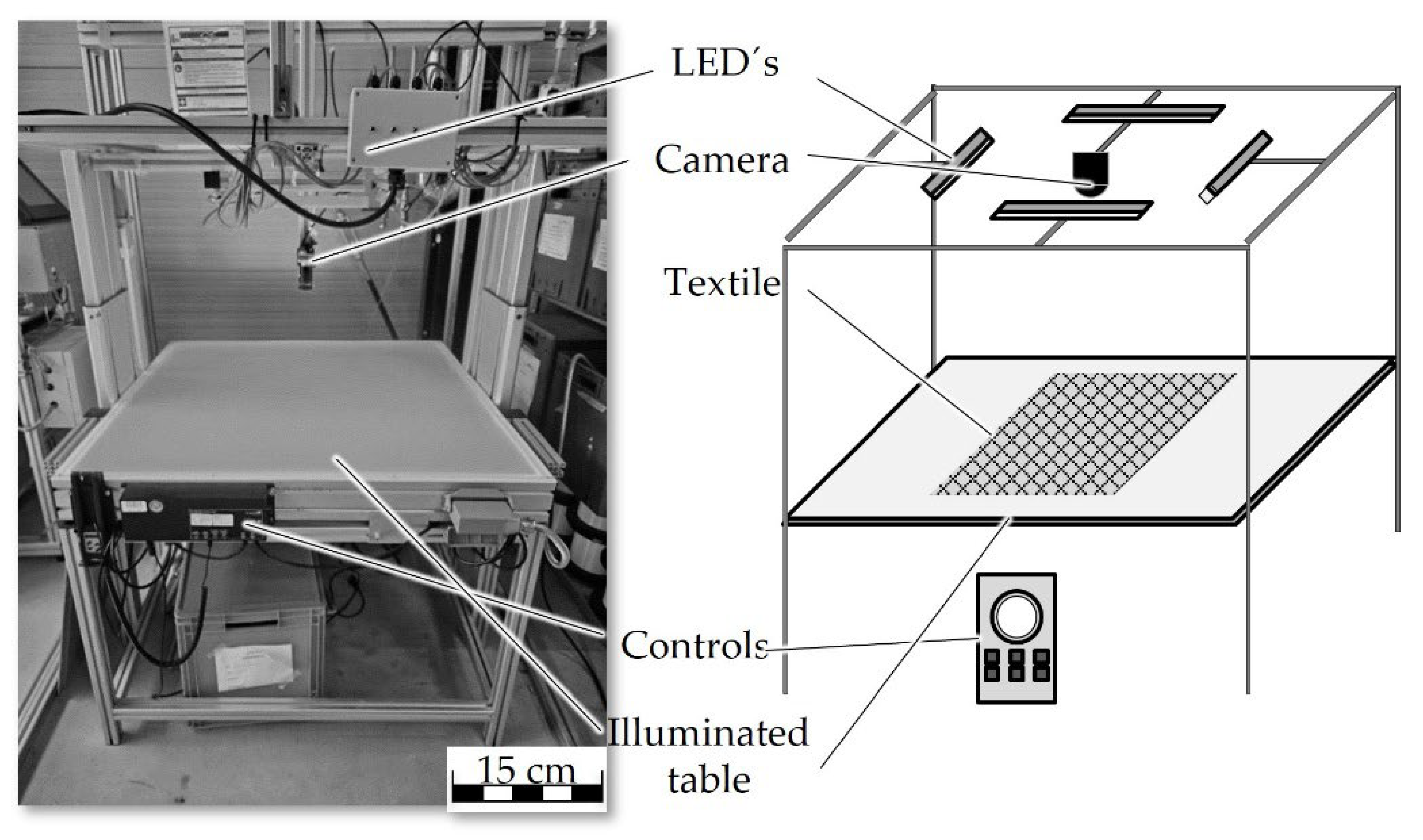
Figure 4.
Reference Picture of cover factor measurement.
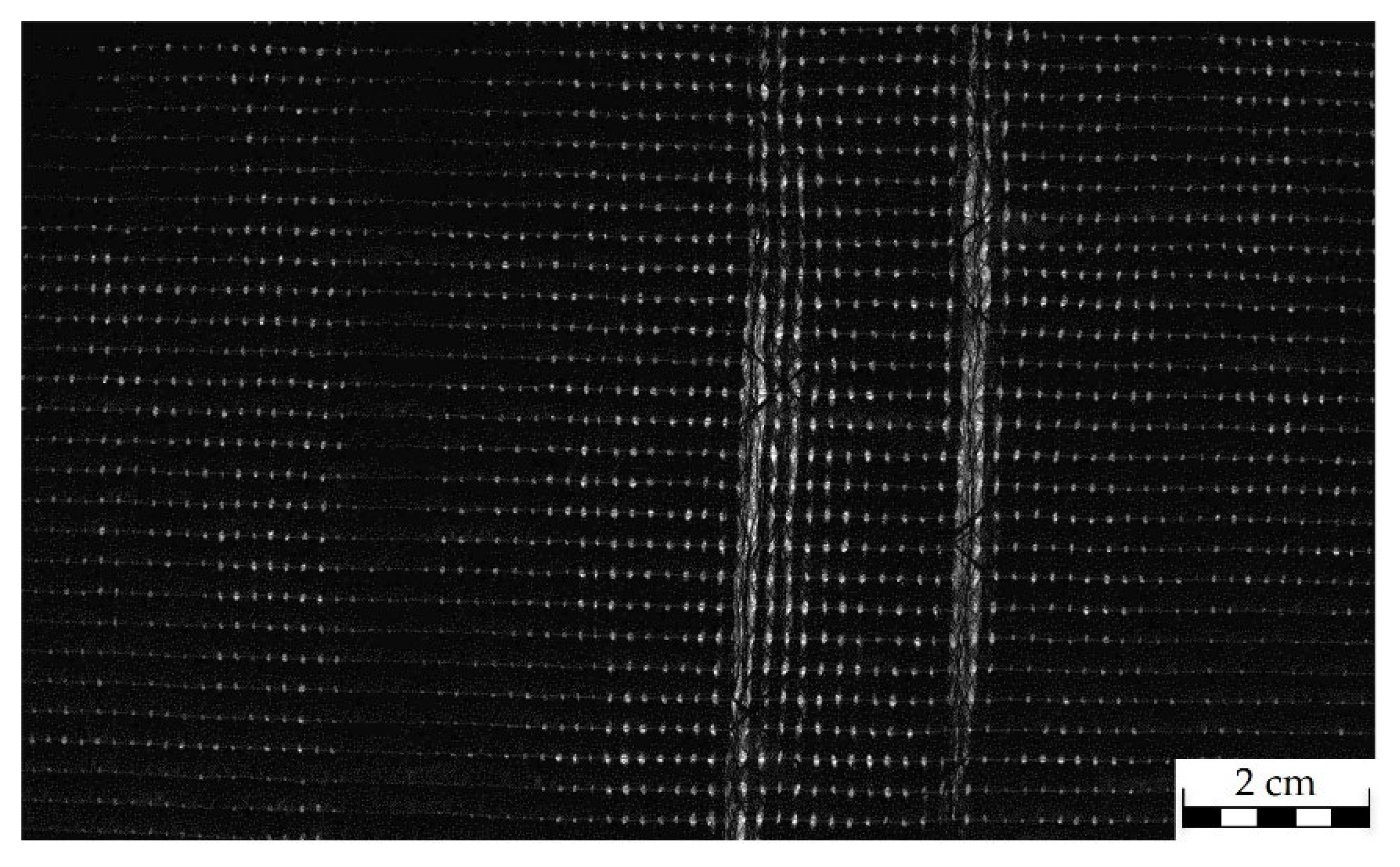
Figure 5.
Aluminium mould with fibre material (left), drawing of mould in press (right).
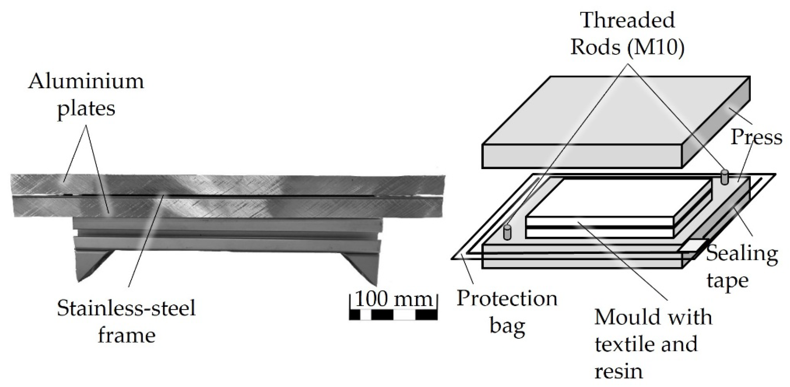
Figure 6.
Resin distribution and void spots in plate B6.
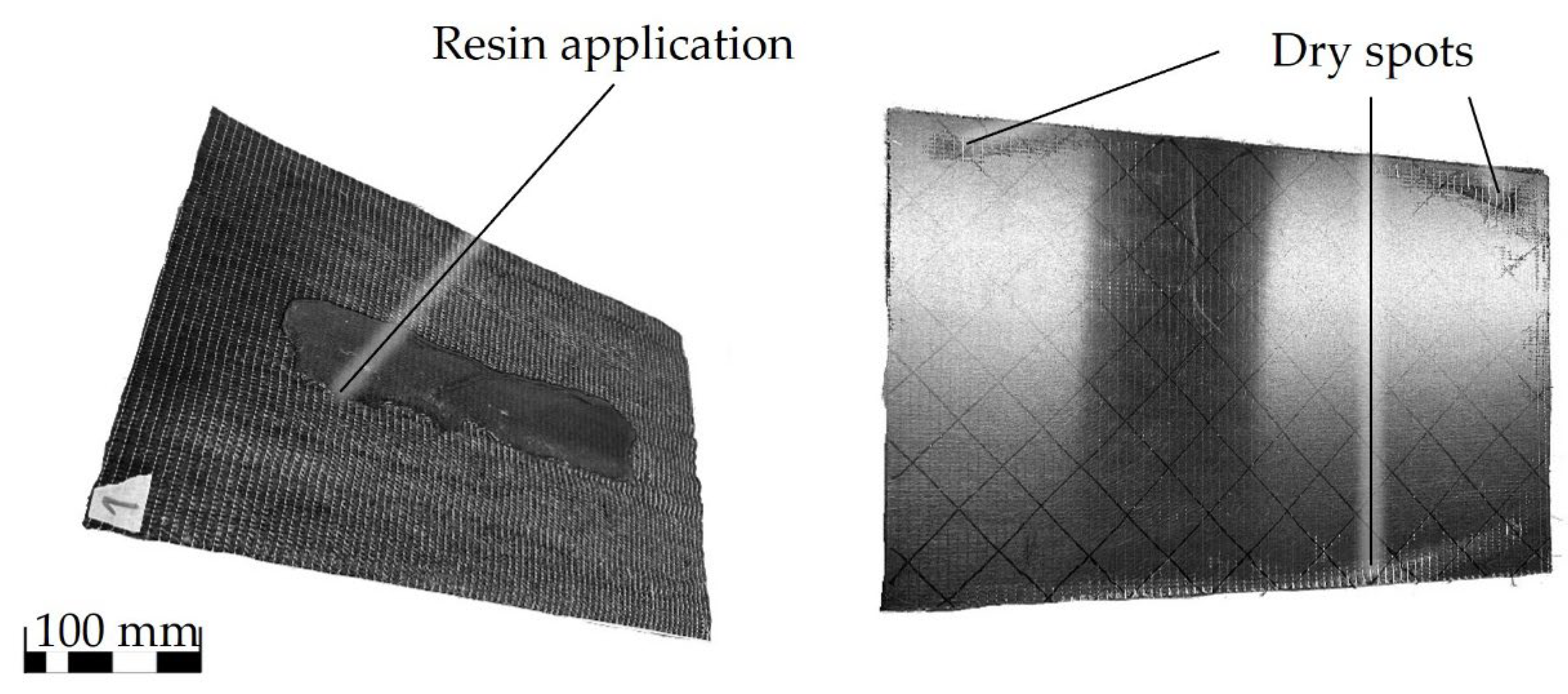
Figure 8.
Flexural stress vs. deformation of samples B3, B6 and reference.
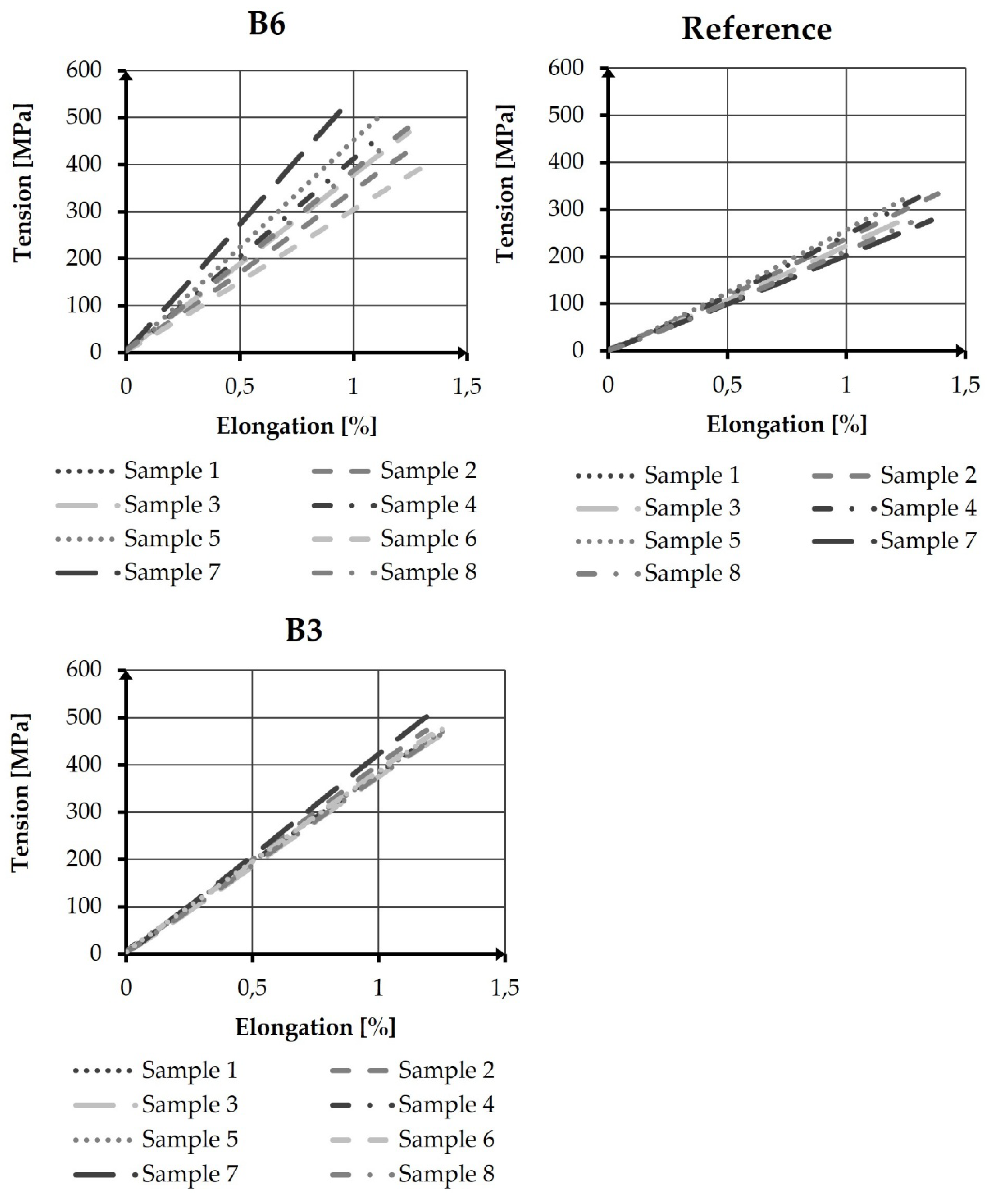
Figure 9.
Bending Samples after testing, left: B3_3, centre: B6_4, R_3.
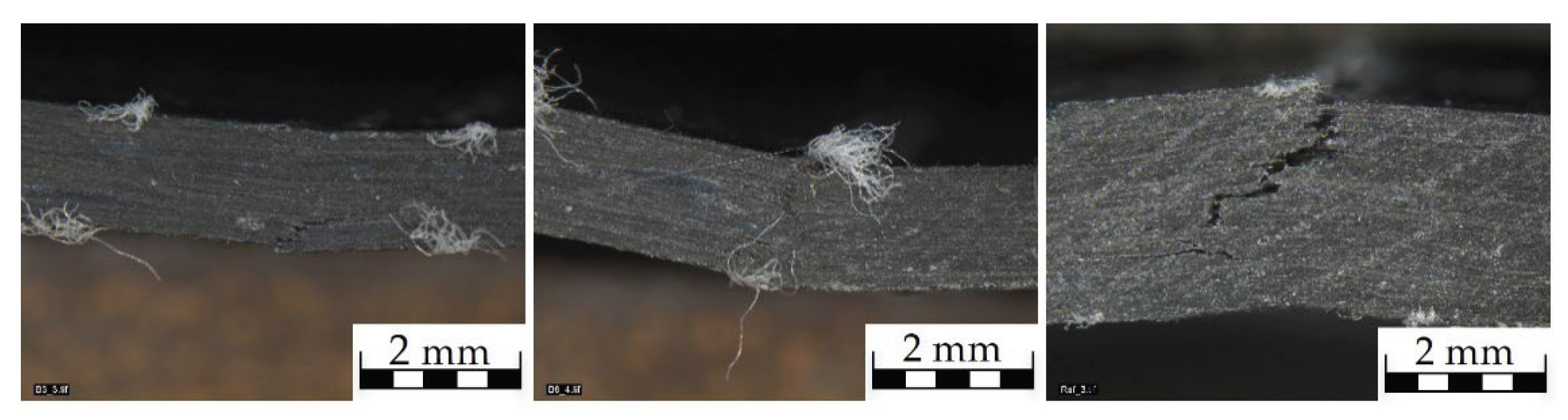
Table 1.
Investigated Samples.
| Sample Name | Process |
| B6 | Compression Moulding |
| B3 | Compression Moulding |
| R | Vacuum Infusion |
Table 3.
Production parameters of different samples.
| No. |
Cover Factor [%] |
Sliver Width [mm] |
Areal weight [gsm] |
Number of Layers [ ] |
FVF [%] |
| B6 | 97,32 | 32,73 ± 3,87 | 258 | 3 | 28 |
| B3 | 96,37 | 30,50 ± 4,2 | 232 | 3 | 26 |
| R | 97,00 | 27,01 ± 5,19 | 242 | 3 | 17 |
Table 4.
Tensile Testing results.
| No. | Number of Samples | FVF [%] | Tensile Strength [MPa]* | Tensile Strength [MPa] | Modulus [GPa] | Elongation at Fmax [%] |
| B6 | 8 | 27 | 581 ± 90 | 523 ± 81 | 39 ± 7 | 1,30 ± 0,05 |
| B3 | 8 | 26 | 559 ± 41 | 584 ± 35 | 38 ± 1 | 1,26 ± 0,07 |
| R | 7 | 17 | 550 ± 49 | 312± 28 | 22 ± 2 | 1,32 ± 0,06 |
*normalized to 30 % FVF.
Disclaimer/Publisher’s Note: The statements, opinions and data contained in all publications are solely those of the individual author(s) and contributor(s) and not of MDPI and/or the editor(s). MDPI and/or the editor(s) disclaim responsibility for any injury to people or property resulting from any ideas, methods, instructions or products referred to in the content. |
© 2025 by the authors. Licensee MDPI, Basel, Switzerland. This article is an open access article distributed under the terms and conditions of the Creative Commons Attribution (CC BY) license (http://creativecommons.org/licenses/by/4.0/).
Copyright: This open access article is published under a Creative Commons CC BY 4.0 license, which permit the free download, distribution, and reuse, provided that the author and preprint are cited in any reuse.


