
Submitted:
11 August 2025
Posted:
13 August 2025
You are already at the latest version
Abstract
In the multi-degree of freedom portion of the undergraduate vibrations engineering course taught at the United States Military Academy and West Point, New York, in-structors ask the students (a) how we identify system parameters of effective mass and/or mass moment of inertia, stiffness, and damping as well as (b) whether our implicit as-sumption, that these properties were constant for systems in motion, was valid. Instructors then use concepts from several other engineering courses along with an introduction to experimental methods to answer these questions.
One set of answers to these questions came from the analysis of the elastic vibration of a tail-rotor blade from a U.S. Army UH-1H “Huey” helicopter. This analysis required the integration of fields of vibrations engineering with dynamics and mechanics of materials. Use of modal analysis empirically determined three out-of-plane flapping modes as well a torsional mode of vibration for a nonrotating blade. For this modal analysis, a Brüel and Kjær 2034 signal analyzer was used to gather frequency response functions of the stationary rotor blade as excited by an impact hammer. The response to the excitation was measured with an accelerometer. The centrifugal-stiffening effect of the operational angular velocity of the rotor blade was simulated via structural dynamics modification.
This problem presented many interesting challenges and provided an innovative means of coupling material from different undergraduate courses to solve a real-world engineering problem.
Keywords:
helicopter
; tail-rotor blade
; modal analysis
; structural dynamics modification
; centrifugal-stiffening
1. Introduction
There is a long history of helicopter vibration studies. Nygren [1] investigated helicopter higher harmonic control using a dynamic system coupler simulation for his Ph.D. dissertation. He also published a test plan using the Langley Rotorcraft Structural Dynamics Program to develop an efficient means of coupling a main rotor to the airframe [2]. Additionally, Nygren and Schrage studied fixed-gain versus adaptive higher harmonic control simulation [3]. Grappasonni, et-al., [4] studied the vibrations in a Lynx Mk7 airframe and an AgustaWestland lightweight helicopter tail frame without the tail-rotor. Results were quantified via Modal Assurance Criterion diagrams. Rizo-Patron and Sirohi studied the theoretical and empirical modal analysis of the first three out-of-plane flapping modes of a beam simulating a helicopter rotor, using digital image correlation as the beam rotated at 0, 300, 600, and 900 RPM [5]. Torsion was not studied. This paper included a centrifugal stiffening term which involved mass per unit length and the square of Ω, the speed of rotation. Pierro, et-al., studied the vibro-acoustical operational modal analysis of a helicopter cabin [6]. Agneni, et-al., studied the output-only modal analysis of a rotating helicopter blade in the German Aerospace Center [7]. Ameri, et-al., conducted ground vibration tests of a helicopter frame [8]. Sibille, et-al., investigated the automated operational modal analysis of a Airbus Helicopter H135 bearingless main rotor blade with a density-based cluster algorithm [9].
Češkovič, et-al., investigated unwanted supplementary vibrations of helicopter radio communication systems [10]. Tamer, Aet-al., focused on a generalized index for the assessment of helicopter pilot vibration exposure [11]. Chiariello, et-al., published their results on the vibration qualification campaign on the main landing gear system for a high-speed compound helicopter [12]. Yang, et-al., reduced helicopter vibration loads by individual blade control with a genetic algorithm [13]. Bertolino, et-al., developed of a high-performance low-weight hydraulic damper for active vibration control of the main rotor on helicopters [14,15]. Wang, et-al., evaluated a topological valley stamping plate for low-frequency-vibration isolation and wave manipulation in helicopters [16]. Tamer, et-al., studied cabin layout optimization for vibration hazard reduction in helicopter emergency medical service [17]. Feng [18] developed a method of eliminating helicopter vibration interference magnetic field with a pair of magnetometers. Our study differed from these by our constructing a stationary model of a helicopter tail-rotor blade using the STAR7 software from Spectral Dynamics. Then we augmented this stationary model to an operational rotating velocity via use of the STAR7 Structural Dynamics Modification.
2. Modal Measurements at the United States Military Academy, West Point
The Bell UH-1 Iroquois (nicknamed "Huey") [19] was the beginning of a family of utility military helicopters designed and produced by the American aerospace company Bell Helicopter. It was also the first turbine-powered helicopter in service with the United States military.
Figure 1 shows a Bell UH-1H Iroquois along with the X- and Z-axes used in the coordinate system of this study. This aircraft has a maximum gross weight of 9,500 lbs., a cruise speed of 90 knots, and a maximum speed of 120 knots. It was a tail-rotor blade of this model of helicopter which was loaned for this study by the Second Aviation Detachment stationed at the Steward Army Air Field, Newburgh, New York.
The tail-rotor of the UH-1H helicopter had two blades. The radius R of the arc of the tail-rotor was 1.295 meters (4.25 feet). Its operational angular velocity was Ωz=173.2 radians/second (1,654 RPM) about the horizontal Z-Axis. The Y-Axis chord of the largely rectangular blade was 213.6 mm (8.41 inches). The mass of the one blade was approximately 3 kg and the overall blade length along the X-Axis was L=1.16 meters. The center of mass was located 0.685 meters from the outer edge, 0.475 meters from the inner edge of the blade. Two mount holes, 30 mm from the root end of the blade, were used to cantilever the tail-rotor blade from a steel channel, as shown in Figure 2.
The empirical modal analysis of one tail-rotor of a Bell UH-1H Iroquois “Huey” military helicopter was done in lab D-18, Mahan Hall, the United States Military Academy at West Point, New York. Figure 2 shows the layout of 45 nodes along the top surface of the UH-1H tail-rotor blade, which is effectively a fixed-free cantilever beam. A Brüel & Kjær 4393 Accelerometer (fixed-location response, in m/s2) [21] was mounted at the radially outermost node along the trailing edge of the tail-rotor blade (node 16), Figure 2, with beeswax. It was felt that measuring the system response at this node would afford the maximum sensitivity to both flapping and torsion and would not be a vibrational node (point of zero amplitude for any of the modal resonances). The end view of the tail-rotor blade in Figure 2 was photographed at the Pima Air and Space Museum, [22]. This blade rotated clockwise about the Z-axis.
As shown in Figure 3, a Brüel & Kjær 8202 impact hammer and 8200 force transducer (excitation, in Newtons) [23] were used to gently tap the 45 nodes, and the fixed location Brüel & Kjær 4393 accelerometer sensed the subsequent response. Using the hard-rubber tip, without the additional mass, on the 8202 impact hammer limited the excitation to 500Hz, coinciding nicely with the 400Hz bandwidth on the Brüel & Kjær 2034 Analyzer. Brüel & Kjær 2644 line-driver charge-amplifiers [24] amplified the low-level signals from the 4393 accelerometer and 8200 force transducer before these signals were received by the Brüel & Kjær 2034 signal analyzer. The outputs of the Brüel & Kjær 2034 signal analyzer were 45 Frequency Response Functions (*.FRF). Structural Measurements System (SMS) StarStruc software originally performed the calculation of mode shapes, modal frequency and modal damping ratios, similar to that described by Winarski [25].
Table 1 lists the XYZ coordinates of the 45 nodes comprising the helicopter tail-rotor blade. The nodes were numbered starting along the thickest portion of the blade, then along the trailing edge of the blade, then finally along the leading edge of the blade.
3. Transferring Modal Measurements from SMS StarStruc to Spectral Dynamics STAR7
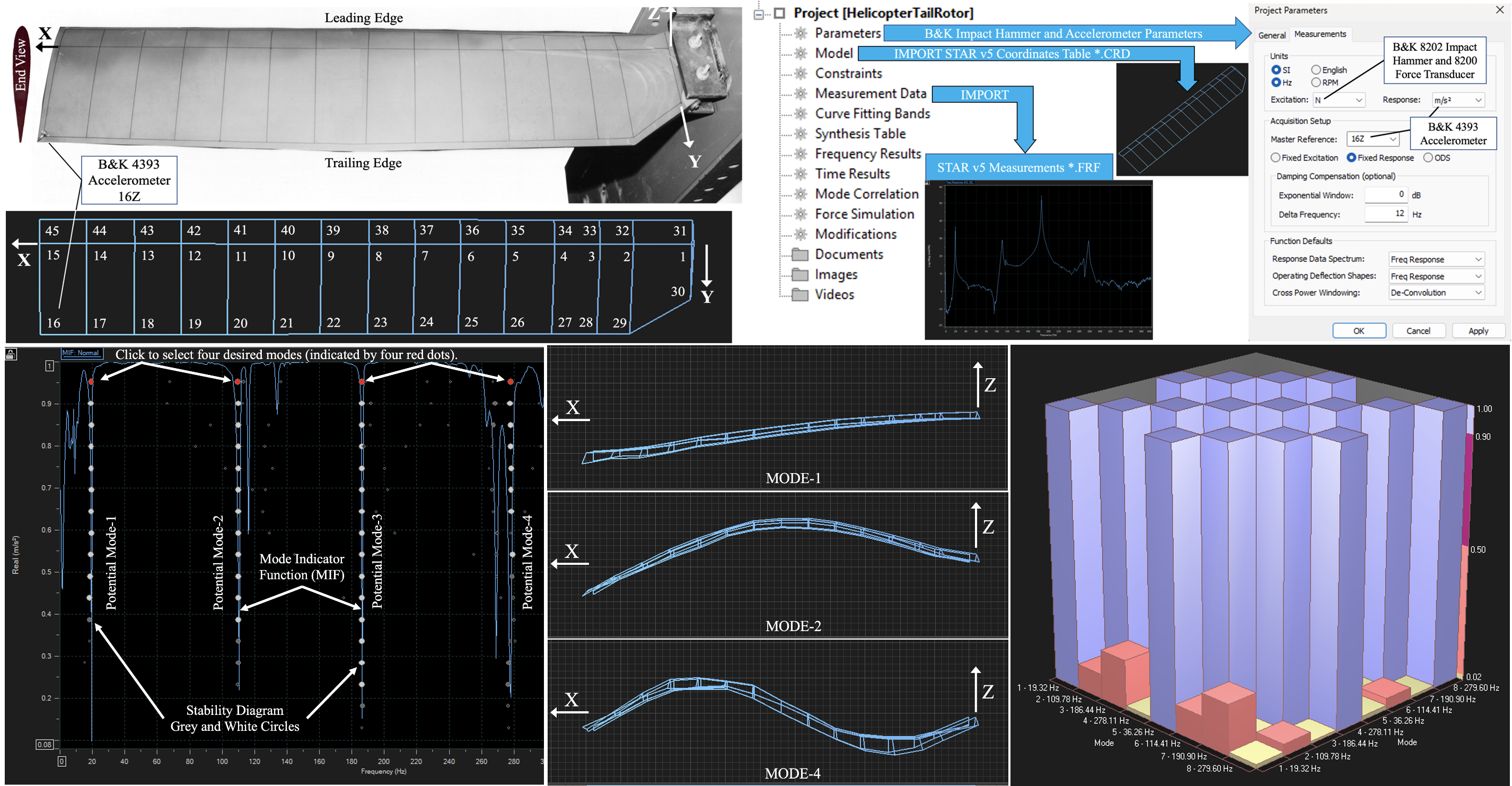
Eventually, this StarStruc software became obsolete. After much detective work, it was determined that GenRad had acquired Structural Measurements System, then Spectral Dynamics had acquired GenRad. Spectral Dynamics took a special interest in advancing this project, including instructions on how to import the old SMS *.CRD coordinate file and the 45 old SMS *.FRF Frequency Response Function files into their latest STAR7 Premier Modal software 3410-9710 [26], as summarized in Figure 4. The old SMS *.DSQ display sequence did not require separate importing.
The transfer of modal results from the old SMS StarStruc package to the new Spectral Dynamics STAR7 package began with creating a workspace then creating a project within that workspace. Once inside that project, as shown in Figure 4, right click on MODEL > IMPORT and select STAR v5 Coordinate Tables (*.CRD). Navigate to the desired SMS *.CRD file and upload it, to produce the basic geometry of the modal analysis. Next, right click on MEASUREMENT DATA > IMPORT and select STAR v5 Measurements. Navigate to the desired SMS *.FRF files, select all using shift-click, and upload them. Lastly, open PARAMETERS and select the units of SI HZ, Excitation in Newtons for the Brüel & Kjær 8202 impact hammer and 8200 force transducer, and Response in m/s2 for the Brüel & Kjær 4393 accelerometer. Under acquisition setup, Fixed Response was selected, and the master reference was 16Z as the 4393 accelerometer was at node 16 in the Z direction. Using the FILE menu, the project was then saved as a new *.PRJ file in the respective *.SWS workspace file, resulting in the model being saved to a new *.CMM file and the measurements being saved to a new *.SDD file.
4. Identifying Modes of Vibration Using STAR7
Figure 5 shows the exemplary 45Z-16Z Frequency Response Function displaying four potential modes of vibration over the frequency range of 0≤ω≤400Hz. 45Z-16Z meant that this was the response at node 45Z with the reference at 16Z, the location of the Brüel & Kjær 4393 accelerometer. 45Z was picked as the exemplary response because it was at the outer extremity of the rotor and at the leading edge of the rotor blade. With the 4393 accelerometer at the outer extremity of the rotor and at the trailing edge of the rotor blade, it was felt that the 45Z-16Z pair gave the best representation of both the flapping and torsional modes of vibration of the subject rotor blade.
The mode identification using the Advanced Curve Fitter method began by selecting Analysis from the top tool bar, then selecting Mode Indicators for all 45 nodes. The creation of the normal (normalized between 0 and 1 as shown on the vertical axis) Mode Indicator Function (MIF) is shown as the blue line in Figure 6.
Next, the Stability Diagram icon was selected, to superimpose the circles of the Stability Diagram upon the Mode Indicator function in Figure 5. From the Estimate FD tab, select Model Size from 4 to 20 and click Calculate. If a potential mode was found, the Stability Diagram reported an open circle. If the same mode was stable within the frequency tolerance, a light gray circle was reported. If both the difference in frequency and damping values were within tolerance, the new circle was shaded light gray. If both the difference in frequency and damping values were in tolerance, the new circle was shaded dark gray. If the frequency and damping values were again in tolerance, the new circle was shaded white. A progression of dark grey circles followed by white circles was clearly evident in Figure 6. In order to calculate the four mode shapes seen in Figure 7 and Figure 8, each mode had to be selected by clicking on one of the circles, as shown by the four red circles, then selecting Analysis > Curve Fitting > Poly-Reference and clicking on Fit All.
5. Output of STAR7
Figure 7 shows flapping modes 1, 2, and 4 from the perspective of the X-Z plane, which best differentiates between the three distinctive mode shapes for a nonrotating tail-rotor blade, Ωz=0.
Figure 8 then shows an isometric view of torsional mode-3, to better visualize the rotational-deflection of the nonrotating tail-rotor blade about the X-axis.
The information from Figure 7 and Figure 8 is summarized in Table 2, where the modes are numbered in order of frequency. The frequencies and damping determined by STAR7-ACF were very close to the previous SMS StarStruc software values obtained using the polynomial method.
Table 3 lists the empirical frequency ratios in column 3 for the three STAR7 flapping frequencies in column 2, from Table 2. The ratio of 5.68:1 was calculated from the quotient 109.78/19.32, and the ratio of 14.39:1 was calculated from the quotient 278.11/19.32.
In column 4 of Table 3, the corresponding theoretical frequency ratios were listed from Blevins [27], for an Euler-Bernoulli beam of uniform cross-section. In column 4, the ratio of 6.267:1 was calculated from (λ2/λ1)2, where λ2=4.69409113 and λ1=1.87510407. Similarly, the ratio of 17.547:1 was calculated from (λ3/λ1)2, where λ3=7.85475744.
In columns 5-7 of Table 3, the corresponding theoretical frequency ratios were listed from Yoo and Shin [28], Wright, et-al., [29], and Lima [30], respectively. Columns 4-7 indicated a reasonable agreement between the published Euler-Bernoulli theory and the experimental results from the tail-rotor blade using STAR7, as tabulated in column 3. The =PEARSON correlation between the STAR7 frequency ratios in column 3 of Table 3 and the Blevins frequency ratios in column 4 and Lima ratios in column 7 was 99.9%, indicating a very strong correlation between our stationary tailrotor blade and a stationary Euler-Bernoulli beam.
6. STAR7 Modal Assurance Criterion, Ωz=0
In Figure 9, the 3-D histogram (left) and 2-D table (right) Modal Assurance Criterion [31] for the STAR7 Advanced Curve Fitter are displayed for the four modes of vibration of interest shown in Figure 7 and Figure 8, at Ωz=0. Pastor [32] was helpful in understanding Figure 9.
In Figure 9, the MAC is a symmetric 4-by-4 matrix calculated by the dot product of eigenvectors of pairs of the four subject modes. The comparison values for each pair of modes varied between 0 and unity (100%). The main-diagonals in Figure 9 represented a form of autocorrelation and all were unity, as expected. A form of cross-correlation is shown for half of the off-diagonal elements (6 total) is depicted via a histogram then tabulated for all off-diagonal elements (12 total).
The color coding for Figure 9 was as follows: purple represented a value between 0.90 (90%) and 1.00 (100%) as used for the main-diagonal values, burnt-orange represented a value between 0.50 (50%) and 0.90 (90%), pink represented a value between 0.02 (2%) and 0.50 (50%) as used for several off-diagonal values, and yellow-lime represented a value between 0 (0%) and 0.02 (2%) as used for several off-diagonal values. The low off-diagonal values in Figure 9 indicated a high degree of orthogonality between modes 1-4, as desired.
7. STAR7 Structural Dynamics Modification: DOF-to-Ground for Ωz=173.2 rad/sec
The STAR7 DOF-to-ground structural dynamics modification [30] was chosen to add stiffness to the tail-rotor blade. This simulated the centrifugal stiffening caused by the rotation of the blade when in operation at Ωz=173.2 radians/second (1,652 RPM), Table 4.
Assuming a nodal mass of m=60 grams across all 45 nodes gave a spring rate in the Z direction of Kz=mΩz2 =1800N/m. The nodal mass of m=60g gave a mass of 2.7kg (45 times 0.06), which allowed about 0.3kg for the attachment stem at the base of the blade. Each DOF-to-ground connection was made using the entries in Table 4, specifying the use of spring modifications via N/m in column 3, the actual stiffness (spring rate) desired which was 1800N/m in column 4, the degree of freedom to be stiffened in the Z out-of-plane direction in column 5, the other end of the spring being attached to ground in column 6, and the default values of ground to be (X,Y,Z) = (0,0,0) in columns 7-9.
Spring rates in the Z direction were calculated as Kz=mΩz2 N/m. The Z-axis was chosen for the DOF-to-ground structural dynamics modification because all four modes of vibration consisted of out-of-plane Z-axis motion. Figure 7 clearly showed that the flapping modes 1, 2, and 4 had their displacements in the Z-direction. Although Figure 8 showed that the torsion mode-3 rotated about the X-axis, this torsion mode comprised the leading edge of the tail-rotor blade displacing in one Z-axis direction and the trailing edge of the tail-rotor blade displacing in the opposite Z-axis direction. Thus, all four subject modes involved Z-axis motion.
Table 5 first lists the STAR7 frequency and damping for modes 1-4, at zero angular velocity, as previously listed in Table 2. Modes 5-8 are modes 1-4 respectively, with structural dynamics modification (SDM), specifically springs specified in Table 4 which were designed to simulate centrifugal stiffening that tended to straighten the helicopter tail-rotor blade and raise modal frequencies when at its operational angular velocity of 173.2 radians per second.
Yoo and Shin [28] and Lima [30] defined the important constant T, which is the reciprocal of the square root used by Blevins [27]. T has the units of seconds.
Yoo and Shin [28] and Lima [30] then defined the nondimensional rotational velocity used to calculate γ=5.017, which is the product of T and Ωz=173.2 radians/second.
This nondimensional rotational velocity was critical for calculating the flapping frequency ratios of 1.839:1 (between mode-5 and mode-1) and 1.156:1 (between mode-6 and mode-2) from both Yoo and Shin [28] and Wright, et-al. [29], as represented in columns 5-6 in Table 6. The value of 1.839:1 was very close to the STAR7 value of 1.877:1, when comparing mode-5 (mode-1 with SDM) and mode-1 itself. The value of 1.059:1, when comparing mode-8 (mode-4 with SDM) and mode-4 itself, was inferred from Figure 2 of Yoo and Shin [28].
Figure 10 and Table 6 show the following. The STAR7 SDM model of the helicopter tail-rotor blade shows that the ratios between the operational (Ωz=173.2 rad/sec) versus stationary (Ωz=0) decrease with increasing flapping mode. All three modes showed all frequency ratios exceed 1:1 indicating centrifugal-stiffening. Additionally, the STAR7 SDM model slightly exceeded Yoo and Shin [28], and Wright [29] for the first flapping ratio, mode-5:mode-1. However, the STAR7 SDM model was slightly lower than Yoo and Shin [28] as well as Wright [29] for the second flapping ratio, mode-6:mode-2. Lastly, the STAR7 SDM model was slightly lower than Yoo and Shin [28] for the third flapping ratio, mode-8:mode-4. The =PEARSON correlation between the STAR7 frequency ratios in column 4 of Table 6 and the Yun and Shin frequency ratios in column 5 was 99.7%, indicating a very strong correlation between our centrifugally-stiffened tailrotor blade and a centrifugally-stiffened Euler-Bernoulli beam.
8. STAR7 Combined Modal Assurance Criterion, for Ωz=0 and Ωz=173.2 rad/sec
Figure 11 shows a 3-D histogram (left) and a 2-D table (right) Modal Assurance Criterion for Ωz=0 (modes 1-4) and Ωz=173.2 rad/sec (modes 5-8, which are modes 1-4 with structural dynamics modification). Auxiliary thick black lines, superimposed on the 8-by-8 MAC table, divided it into four 4-by-4 quadrants. The upper left-quadrant of the 2-D table MAC in Figure 11 represents the apples-to-apples comparison of modes 1-4 for zero angular velocity, Ωz=0, as previously shown separately in Figure 9. The lower right-quadrant of the 2-D table MAC in Figure 11 is the apples-to-apples comparison of modes 5-8, where modes 1-4 now experience an operational angular velocity of Ωz=173.2 radians per second. Both the upper-left and the lower-right quadrants are symmetric, and the purple main diagonal which they form has values of 100% for an autocorrelation, as expected. The lower-left and the upper right quadrants of the 2-D table MAC in Figure 1 are apples-to-oranges comparisons of modes 1-4 versus modes 5-8. The lower-left and the upper right quadrants are not themselves symmetric about their respective subdiagonals; however, these two quadrants are mirror-images of each other about the main diagonal of Figure 11. Thus, the overall 8-by-8 MAC in Figure 11 is a symmetric matrix, as desired. Additionally, the purple subdiagonals in the lower-left and the upper right quadrants of the 2-D table MAC showed 100% correlations, indicating that the mode shapes in Figure 7 and Figure 8 were not meaningfully affected between the stationary angular velocity of Ωz=0 and the operational angular velocity of Ωz=173.2 radians per second. Yoo and Shin [28] did report shifts in mode shape, but at the nondimensional rotational velocity of γ=50, which was an order of magnitude greater than our value of γ=5.017.
9. Conclusions
To facilitate the understanding of the undergraduate students who have not had courses in helicopter design, the structural modification package of the STAR7 software was used to model the helicopter tail-rotor in its zero angular velocity and its operational mode. In its operational mode, the tail-rotor spins at constant angular velocity Ωz about the horizontal Z-Axis. This rotational motion stiffens the blade beyond the flexural rigidity taught in mechanics of materials. We showed how to implement structural dynamics modification within the Spectral Dynamics STAR7 software, so that future cadets at the United States Military Academy can simulate different flight conditions once a basic modal model is established at a zero angular velocity within a laboratory.
At the point of manufacture, the frequencies and damping obtained by STAR7 could be blockchained [33] to other manufacturing records, for the purpose of determining when a rotor-blade might need replacement.
This study was limited to the analysis of a helicopter tail-rotor blade. Although highly desired, getting a main rotor blade proved impossible. Additionally, when a helicopter turns, coriolois acceleration is developed, which we did not consider.
Author Contributions
Conceptualization, K.L. and D.W.; methodology, D.W.; validation, M.L., D.W. and T.W.; formal analysis, M.L., D.W. and T.W.; investigation, K.L., D.W. and T.W.; writing—original draft preparation, D.W.; writing—review and editing, M.L., K.L., D.W. and T.W.; visualization, K.L. and D.W.; supervision, K.L.; project administration, K.L. All authors have read and agreed to the published version of the manuscript.
Funding
This research received no external funding.
Acknowledgments
Donna Robinson Winarski is acknowledged for her support of this research, both at the United States Military Academy at West Point, New York, and at Tucson, Arizona. Her assistance with initial editing as well as data taking was very much appreciated.
Conflicts of Interest
The authors declare no conflict of interest.
Abbreviations
The following abbreviations were used in this manuscript:
| 2-D | Two dimensional |
| 3-D | Three dimensional |
| *.CMM | STAR7 model file |
| *.CRD | Coordinates file (SMS StarStruc) |
| *.DSQ | Display Sequence file (SMS StarStruc) |
| *.FRF | Frequency Response Function file (SMS StarStruc) |
| *.PRJ | Project file (STAR7) |
| *.SDD | Spectral Dynamics Data file (STAR7) |
| *.SWS | STAR7 workspace file |
| ACF | Advanced Curve Fitter Method (STAR7) |
| B&K | Brüel & Kjær, as of 2019 now called HBK (Hottinger Brüel & Kjær) |
| DOF | Degree Of Freedom |
| E | Effective Youngs Modulus of Tail-Rotor Blade |
| EI | Effective Flexural Rigidity of Tail-Rotor Blade |
| FD | Frequency and Damping |
| I | Effective Area Moment of Inertia of Tail-Rotor Blade about its Neutral Axis |
| Kz | STAR7 SDM Stiffness addition, spring rate in the Z direction |
| L | Length of Tail-Rotor Blade, 1.16m |
| m | Nodal Mass attributed individually to each of the 45 nodes |
| M | Mass per unit length of Tail-Rotor Blade |
| MAC | Modal Assurance Criterion, either a histogram (3-D) or a table (2-D) |
| MIF | Mode Indicator Function (STAR7) |
| R | Arc of the tip of Tail-Rotor, 1.295m |
| RAFA | Rotation About a Fixed Axis |
| SDM | Structural Dynamics Modification |
| SMS | Structural Measurements System |
| STAR7 | Spectral Dynamics modal analysis software |
| T | Vibrational constant, with units of seconds |
| γ | Nondimensional rotational velocity, γ = TΩz |
| ζ | Modal Damping Ratio, in Percent |
| λ | Solutions to the transcendental equation cos(λ)cosh(λ) + 1 = 0 |
| ω | Modal Vibration Frequency, in Hertz |
| Ωz | Angular velocity in rad/sec of the Tail-Rotor Blade about the Z-axis |
References
- Nygren, Kip Peter. "An Investigation of Helicopter Higher Harmonic Control using a Dynamic System Coupler Simulation (Vibrations, Parameter Identification)." PhD diss., Georgia Institute of Technology, 1986.
- Nygren, Kip P. "Calculation of rotor impedance for use in design analysis of helicopter airframe vibrations." Hampton Univ., NASA/American Society for Engineering Educ (1990).
- Nygren, Kip P., and Daniel P. Schrage. "Fixed-gain versus adaptive higher harmonic control simulation." Journal of the American Helicopter Society 34, no. 3 (1989): 51-58. [CrossRef]
- Grappasonni, Chiara, N. Ameri, Giuliano Coppotelli, D. J. Ewins, A. Colombo, E. Bianchi, V. Barraco, and Universit degli Studi di Roma. "Dynamic identification of helicopter structures using operational modal analysis methods in the presence of harmonic loading." In Proceedings of the ISMA. 2012.
- Rizo-Patron, S., and Jayant FSirohi. "Operational modal analysis of a helicopter rotor blade using digital image correlation." Experimental Mechanics 57, no. 3 (2017): 367-375. [CrossRef]
- Pierro, Elena, Emiliano Mucchi, L. Soria, and A. Vecchio. "On the vibro-acoustical operational modal analysis of a helicopter cabin." Mechanical Systems and Signal Processing 23, no. 4 (2009): 1205-1217. [CrossRef]
- Agneni, Alessandro, Giuliano Coppotelli, and Chiara Grappasonni. "Operational modal analysis of a rotating helicopter blade." In Proceedings of ISMA, pp. 16-00184. 2010.
- Ameri, N., Chiara Grappasonni, Giuliano Coppotelli, and D. J. Ewins. "Ground vibration tests of a helicopter structure using OMA techniques." Mechanical Systems and Signal Processing35, no. 1-2 (2013): 35-51. [CrossRef]
- Sibille, Luigi, Marco Civera, Luca Zanotti Fragonara, and Rosario Ceravolo. "Automated operational modal analysis of a helicopter blade with a density-based cluster algorithm." AIAA Journal 61, no. 3 (2023): 1411-1427. [CrossRef]
- Češkovič, Marek, Martin Schrötter, Róbert Huňady, Pavol Kurdel, and Natália Gecejová. 2023. "Unwanted Supplementary Vibrations of Helicopter Radio Communication Systems" Aerospace 10, no. 7: 632. [CrossRef]
- Tamer, Aykut, Andrea Zanoni, Alessandro Cocco, and Pierangelo Masarati. 2021. "A Generalized Index for the Assessment of Helicopter Pilot Vibration Exposure" Vibration 4, no. 1: 133-150. [CrossRef]
- Chiariello, Antonio, Carmine Carandente Tartaglia, Maurizio Arena, Vincenzo Quaranta, Giovanni Bruno, Marika Belardo, and Martina Castaldo. 2024. "Vibration Qualification Campaign on Main Landing Gear System for High-Speed Compound Helicopter" Aerospace 11, no. 2: 130. [CrossRef]
- Yang, Renguo, Yadong Gao, Huaming Wang, and Xianping Ni. 2022. "Reducing Helicopter Vibration Loads by Individual Blade Control with Genetic Algorithm" Machines 10, no. 6: 479. [CrossRef]
- Bertolino, Antonio Carlo, Matteo Gaidano, Stefano Smorto, Paolo Giovanni Porro, and Massimo Sorli. 2023. "Development of a High-Performance Low-Weight Hydraulic Damper for Active Vibration Control of the Main Rotor on Helicopters—Part 1: Design and Mathematical Model" Aerospace 10, no. 5: 391. [CrossRef]
- Bertolino, Antonio Carlo, Matteo Gaidano, Stefano Smorto, Paolo Giovanni Porro, and Massimo Sorli. "Development of a High-Performance Low-Weight Hydraulic Damper for Active Vibration Control of the Main Rotor on Helicopters—Part 2: Preliminary Experimental Validation." Aerospace 10, no. 10 (2023): 868. [CrossRef]
- Wang, Xiong, Changliang Lin, Wei Liu, Jinliang Wang, and Wenjie Wang. 2023. "A Topological Valley Stamping Plate for Low-Frequency-Vibration Isolation and Wave Manipulation in Helicopters" Processes 11, no. 10: 2941. [CrossRef]
- Tamer, Aykut, Vincenzo Muscarello, Giuseppe Quaranta, and Pierangelo Masarati. 2020. "Cabin Layout Optimization for Vibration Hazard Reduction in Helicopter Emergency Medical Service" Aerospace 7, no. 5: 59. [CrossRef]
- Feng, Yongqiang, Yaoxin Zheng, Luzhao Chen, Xiaodong Qu, and Guangyou Fang. 2022. "Method of Eliminating Helicopter Vibration Interference Magnetic Field with a Pair of Magnetometers" Applied Sciences 12, no. 4: 2065. [CrossRef]
- Bell UH-1 Iroquois. Available online: https://en.wikipedia.org/wiki/Bell_UH-1_Iroquois (accessed on 17 July 2025).
- By Airwolfhound from Hertfordshire, UK - UH1 Huey - Fly Navy 2017, CC BY-SA 2.0. Available online: https://commons.wikimedia.org/w/index.php?curid=69215127 (accessed on 19 July 2025).
- Product Data: Piezoelectric Charge Accelerometer Types 4393 and 4393-V. Copyright 2018-08 by Brüel & Kjaer. Available online: https://www.bksv.com/media/doc/bp2043.pdf (accessed on 30 July 2023).
- Bell UH-1H and UH-1C Iroquois (Huey), Pima Air and Space Museum, Tucson, Arizona. Available online: https://pimaair.org (accessed on 24 July 2025).
- Technical Documentation: Impact Hammer Type 8202. Copyright May, 1993 by Brüel & Kjaer. Available online: https://media. hbkworld.com/m/7a8ee3f9bea9db2b/original/Impact-Hammer-Type-8202.pdf (accessed on 30 July 2023).
- Serridge, M.; Licht, T. Piezoelectric Accelerometers and Vibration Preamplifiers: Theory and Application Handbook; Brüel & Kjær: Naerum, Denmark, 1987. Available online: https://www.bksv.com/media/doc/bb0694.pdf (accessed on 30 July 2023).
- Winarski, Daniel, Kip P. Nygren, and Tyson Winarski. 2023. "Modes of Vibration in Basketball Rims and Backboards and the Energy Rebound Testing Device" Vibration 6, no. 4: 726-742. Available online: https://www.mdpi.com/2571-631X/6/4/45. [CrossRef]
- CATS: Computer Aided Test Suite Dynamic Control and Analysis STAR 7 Advanced Modal Analysis. Available online: https://www.scribd.com/document/394925642/665498-MATERIJALI-1-Skripta-Listopad-2013 (accessed on 10 June 2023).
- Blevins, Robert D. Formulas for Natural Frequency and Mode Shape, Reprinted 2001, Krieger Publishing, ISBN 1-57524-184-6, p. 108.
- Yoo, H. H., and S. H. Shin. "Vibration analysis of rotating cantilever beams." Journal of Sound and vibration 212, no. 5 (1998): 807-828. Available online: https://dacemirror.sci-hub.box/journal-article/c37f6aa094b454e18b9a263bb0a3483e/yoo1998.pdf (accessed on 1 August 2025).
- Wright, A. D., C. E. Smith, R. W. Thresher, and J. L. C. Wang. "Vibration modes of centrifugally stiffened beams." (1982): 197-202. [CrossRef]
- Lima, Marco António Costa Fonseca. "Rotating cantilever beams: Finite element modeling and vibration analysis." Master's thesis, Universidade do Porto (Portugal), 2012.
- STAR7 Operating Manual, Rev. 1b, Spectral Dynamics, Inc., San Jose, California. Supplied to STAR7 customers of Spectral Dynamics.
- Pastor, Miroslav, Michal Binda, and Tomáš Harčarik. "Modal assurance criterion." Procedia Engineering 48 (2012): 543-548. [CrossRef]
- Winarski, T. Tsunami of Blockchain Technology and Patents: A Strategic Data Analytic Overview. Jurimetr. J. Law Sci. Technol. 2023, 64, 79–102.
Figure 1.
Bell UH-1H Iroquois [20] with Coordinate System.
Figure 1.
Bell UH-1H Iroquois [20] with Coordinate System.
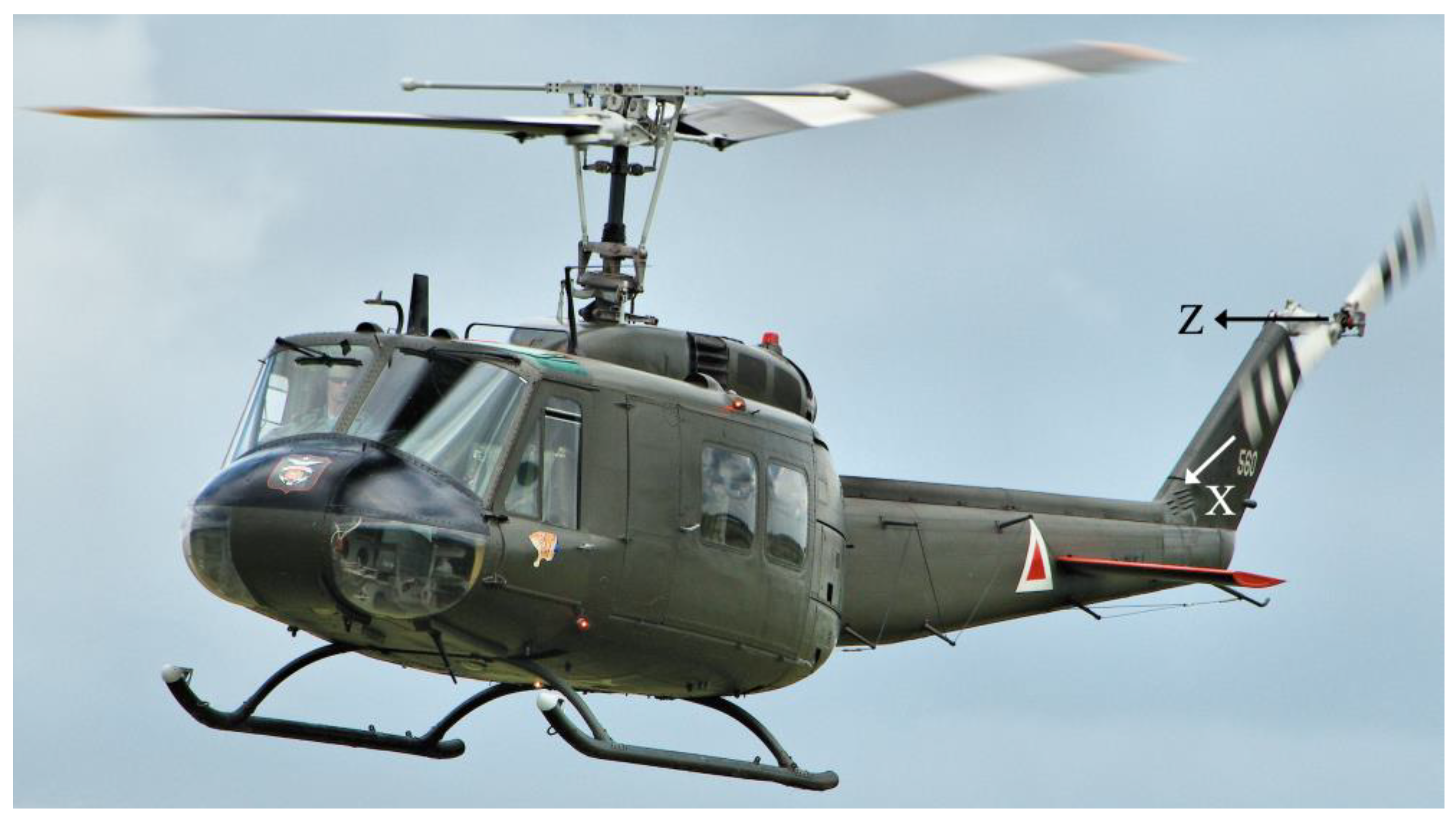
Figure 2.
Layout of 45 Nodes along the Top Surface of the UH-1H Tail-Rotor Blade.
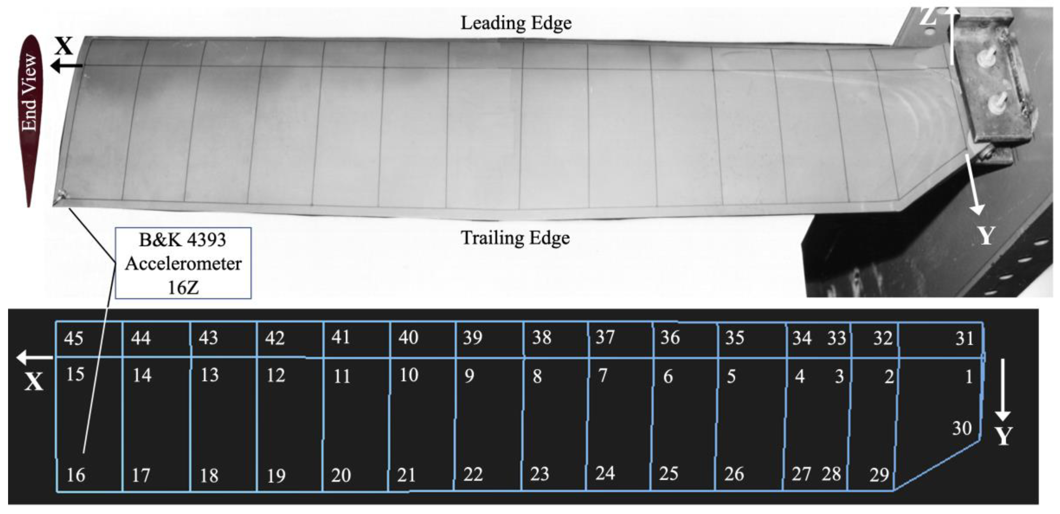
Figure 3.
Diagram of Experimental Setup.
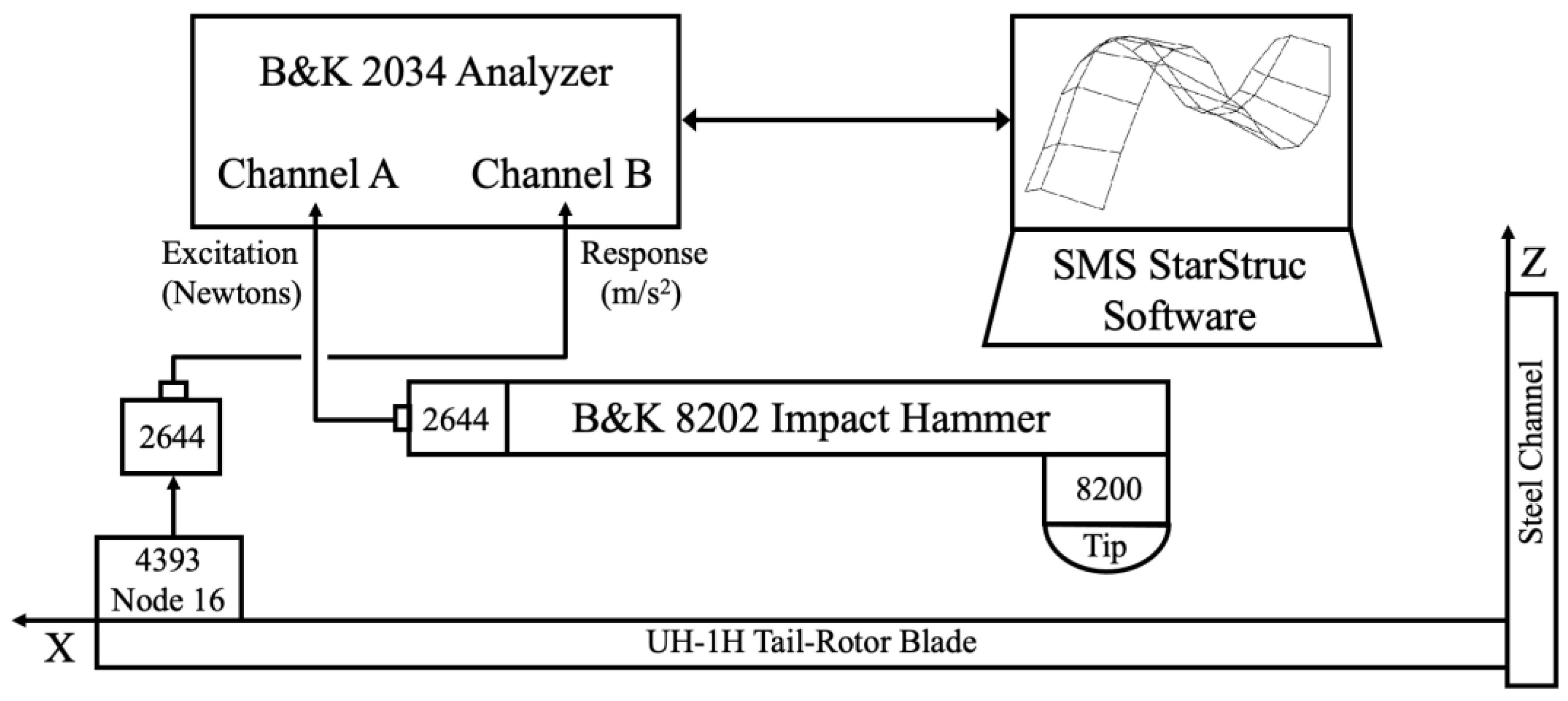
Figure 4.
Transfer from old SMS StarStruc package to the new Spectral Dynamics STAR7.
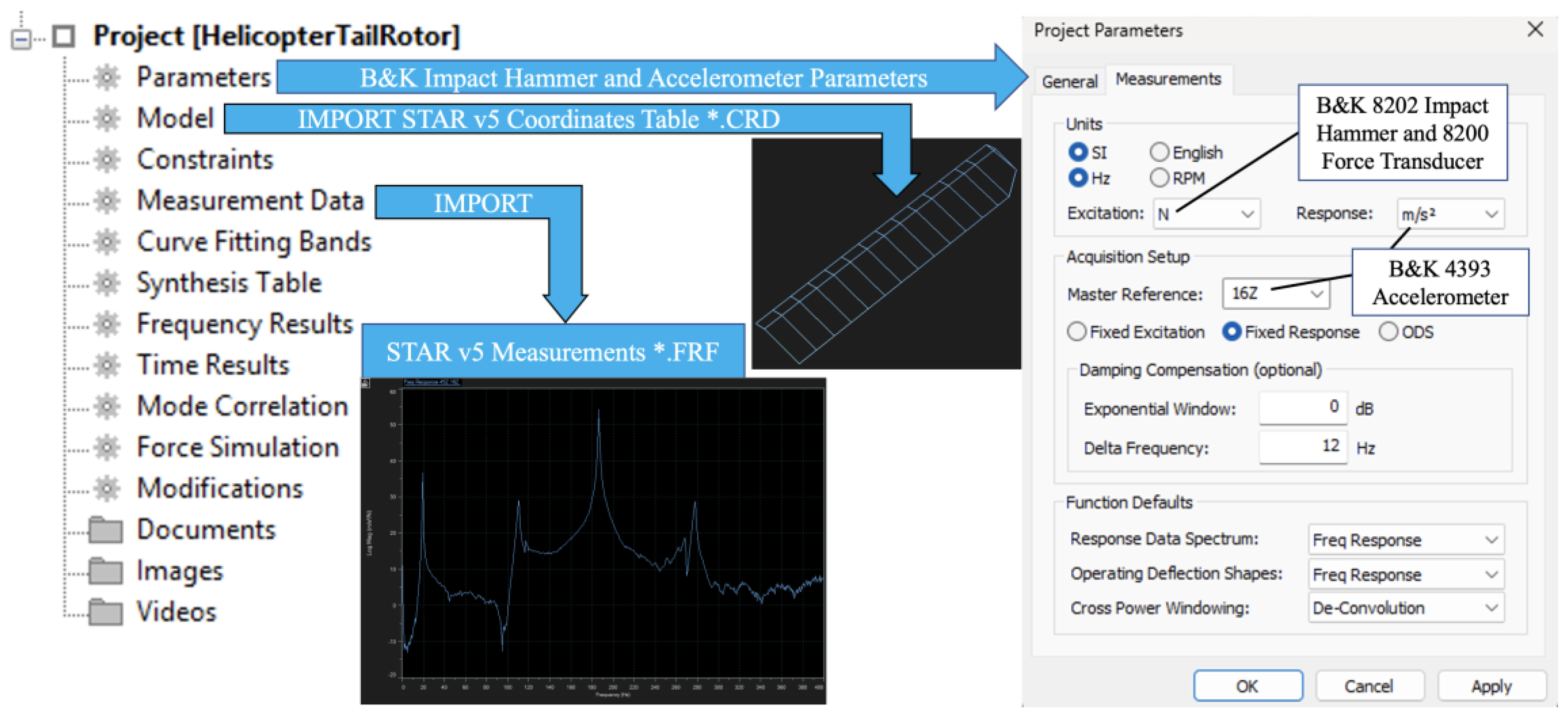
Figure 5.
45Z-16Z Frequency Response Function displaying four potential modes.
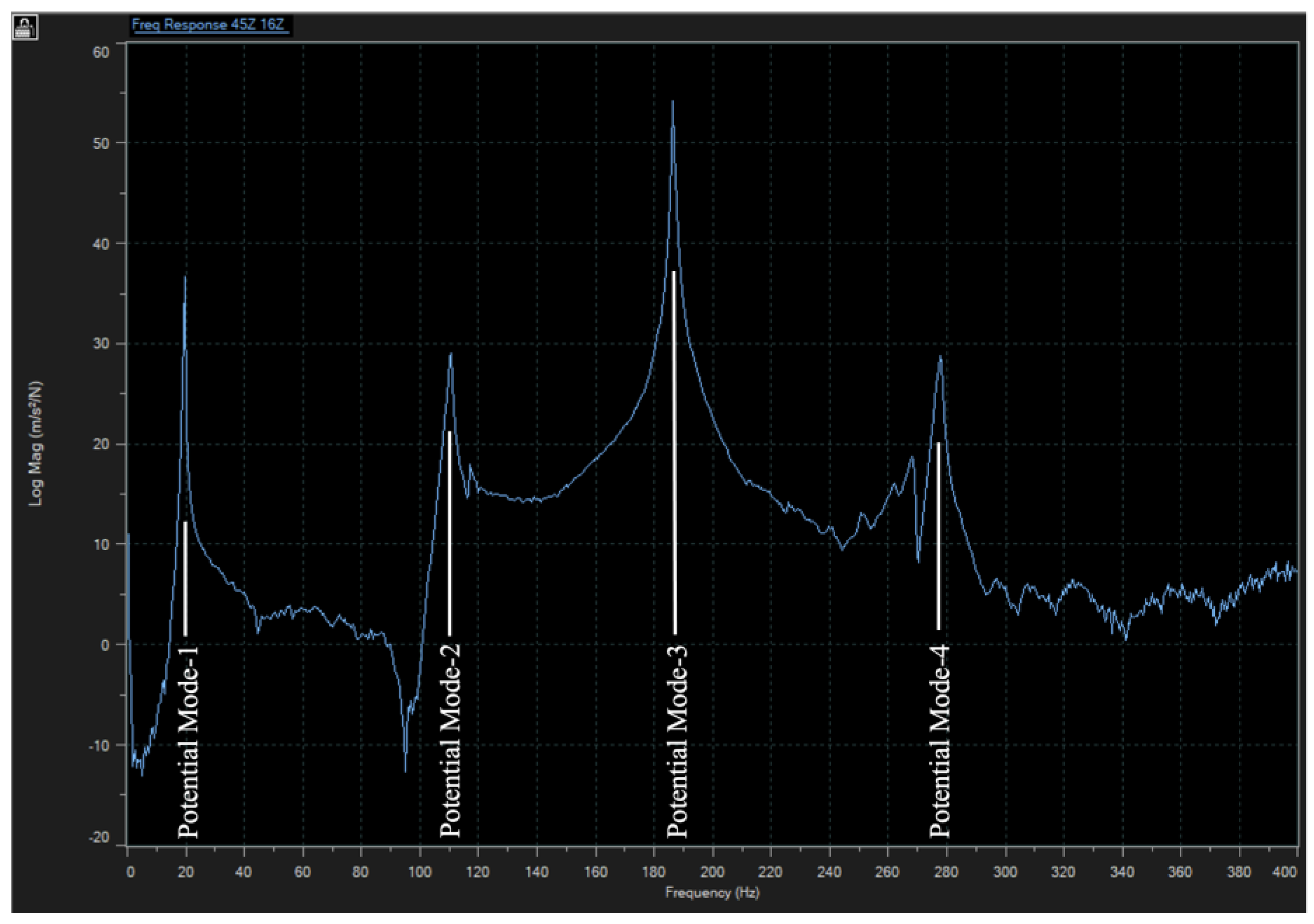
Figure 6.
Advanced Curve Fitter Method showing Mode Indicator Function.
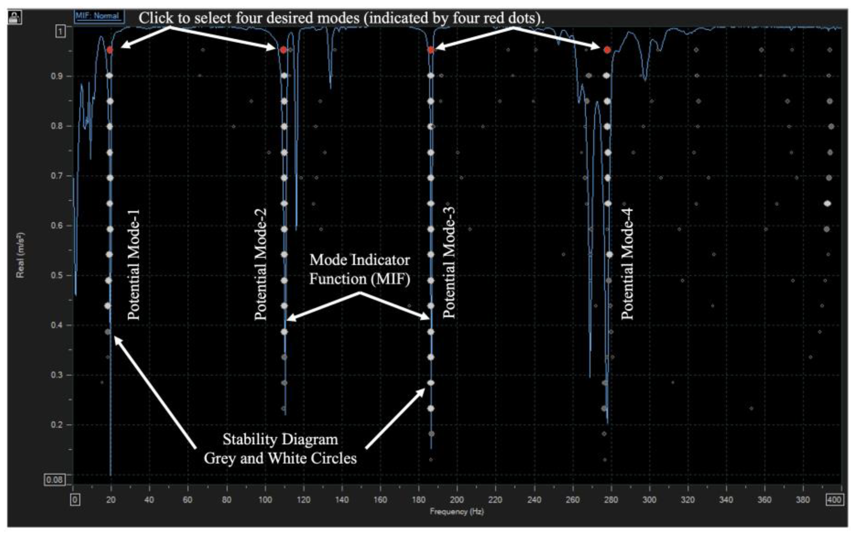
Figure 7.
Flapping Modes 1, 2 and 4, using the Advanced Curve Fitter method, Ωz=0.
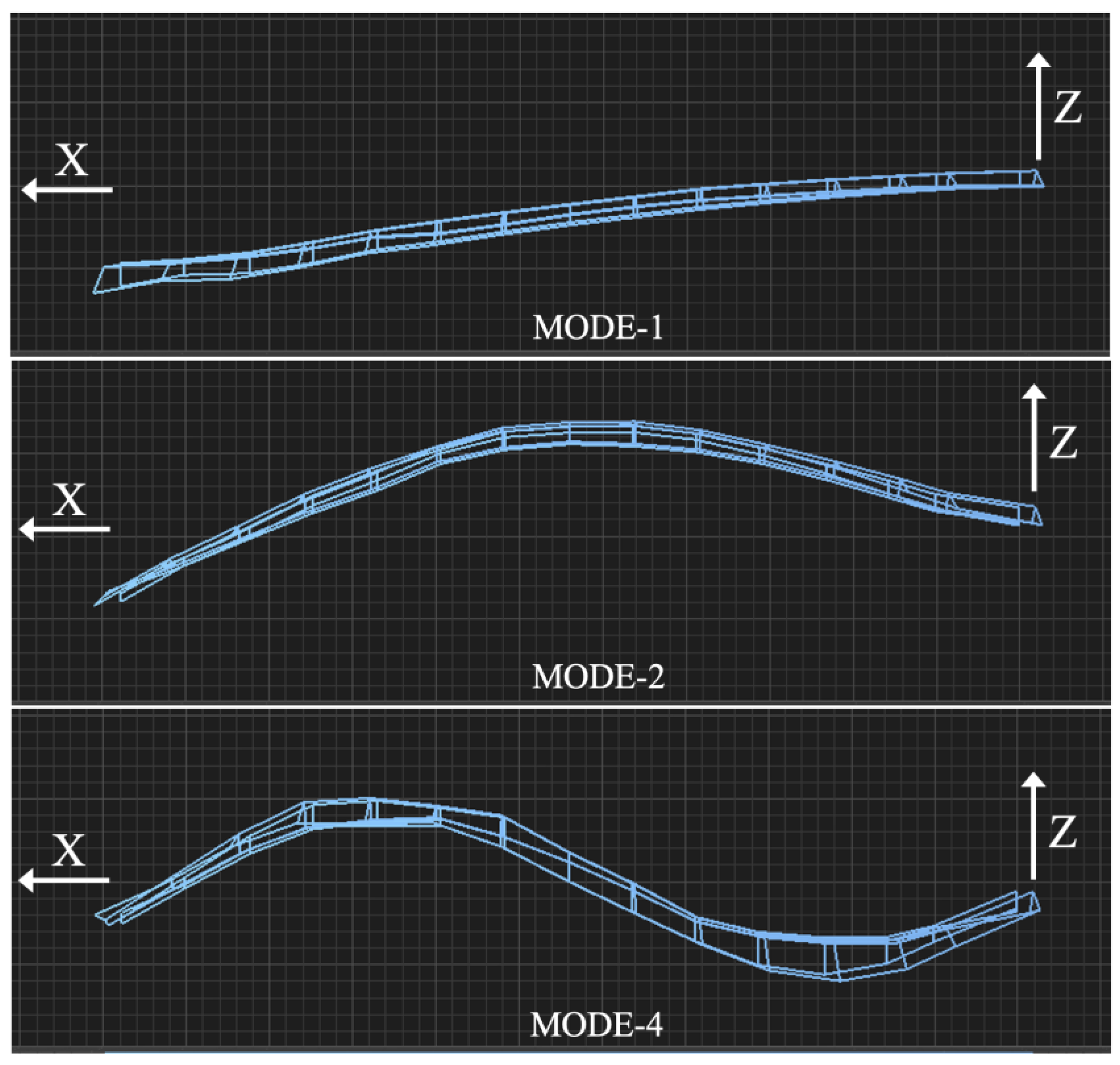
Figure 8.
Torsion Mode-3 using the Advanced Curve Fitter method, Ωz=0.
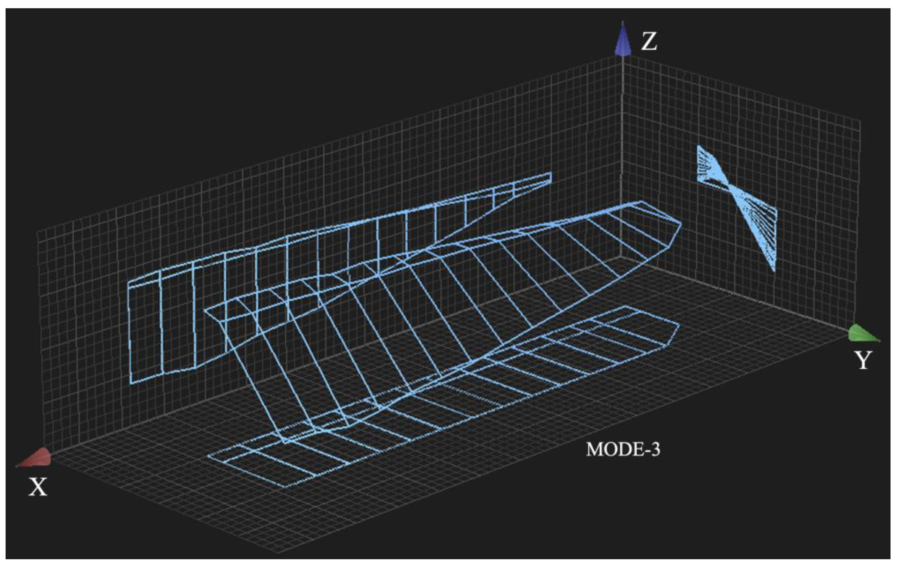
Figure 9.
3-D histogram (left) and 2-D table (right) Modal Assurance Criterion, Ωz=0.
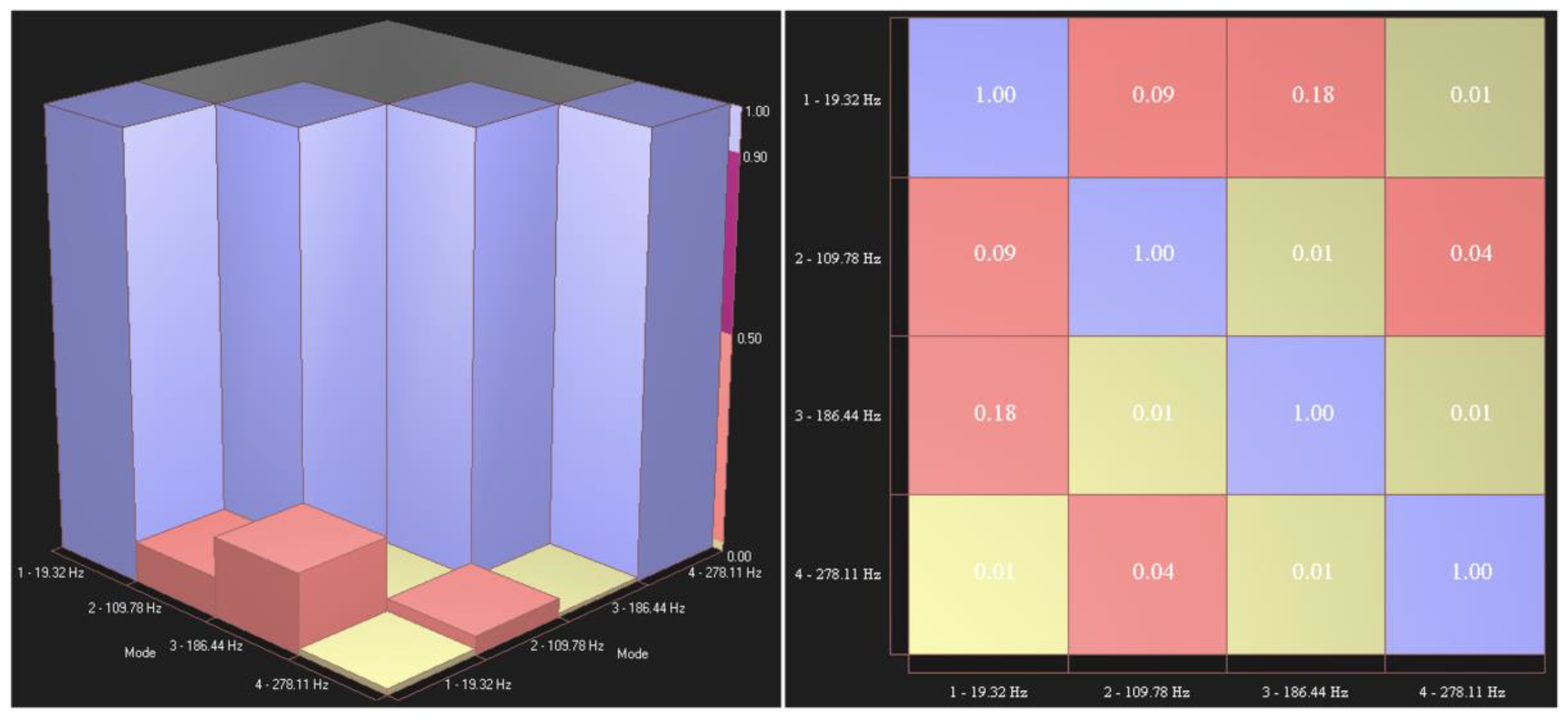
Figure 10.
Frequency Ratio: Operational (Ωz=173.2) versus Stationary (Ωz=0).
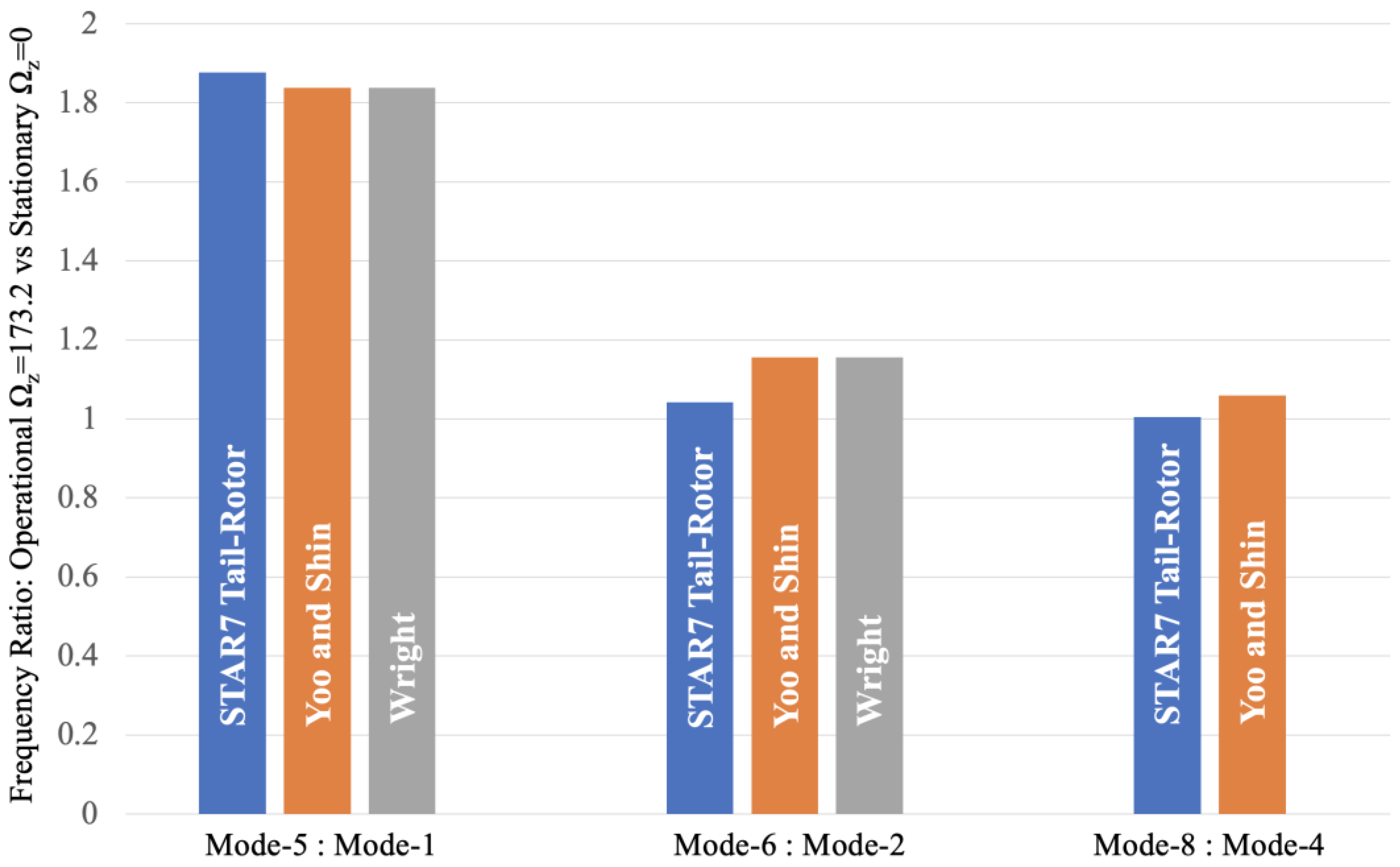
Figure 11.
3-D (left) and 2-D (right) Modal Assurance Criterion, Ωz=0 and 173.2 rad/sec.
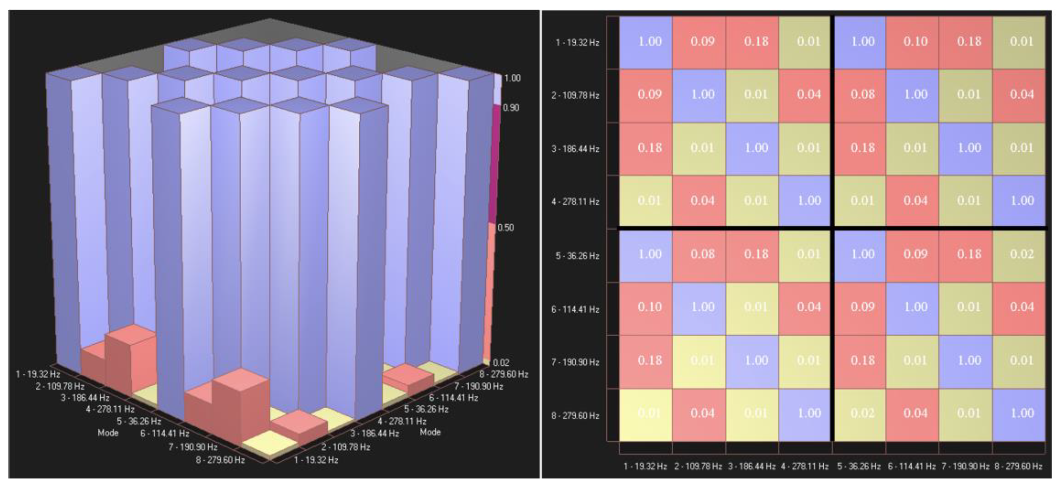

Table 1.
45 Star7 Modal Nodes comprising the Helicopter Tail-Rotor Blade.
| Star7 Node |
X (m) |
Y (m) |
Z (m) |
Rotor Blade Component |
Star7 Node |
X (m) |
Y (m) |
Z (m) |
Rotor Blade Component |
|---|---|---|---|---|---|---|---|---|---|
| 1 | 0 | 0 | 0.02 | Max Thick | 2 | 0.10 | 0 | 0.02 | Max Thick |
| 3 | 0.16 | 0 | 0.02 | Max Thick | 4 | 0.23 | 0 | 0.02 | Max Thick |
| 5 | 0.31 | 0 | 0.02 | Max Thick | 6 | 0.38 | 0 | 0.02 | Max Thick |
| 7 | 0.46 | 0 | 0.02 | Max Thick | 8 | 0.54 | 0 | 0.02 | Max Thick |
| 9 | 0.61 | 0 | 0.02 | Max Thick | 10 | 0.69 | 0 | 0.02 | Max Thick |
| 11 | 0.76 | 0 | 0.02 | Max Thick | 12 | 0.84 | 0 | 0.02 | Max Thick |
| 13 | 0.92 | 0 | 0.02 | Max Thick | 14 | 1.00 | 0 | 0.02 | Max Thick |
| 15 | 1.07 | 0 | 0.02 | Max Thick | 16 | 1.07 | 0.16 | 0 | B&K 4393 |
| 17 | 1.00 | 0.16 | 0 | Trailing | 18 | 0.92 | 0.16 | 0 | Trailing |
| 19 | 0.84 | 0.16 | 0 | Trailing | 20 | 0.76 | 0.16 | 0 | Trailing |
| 21 | 0.69 | 0.16 | 0 | Trailing | 22 | 0.61 | 0.16 | 0 | Trailing |
| 23 | 0.54 | 0.16 | 0 | Trailing | 24 | 0.46 | 0.16 | 0 | Trailing |
| 25 | 0.38 | 0.16 | 0 | Trailing | 26 | 0.31 | 0.16 | 0 | Trailing |
| 27 | 0.23 | 0.16 | 0 | Trailing | 28 | 0.16 | 0.16 | 0 | Trailing |
| 29 | 0.10 | 0.16 | 0 | Trailing | 30 | 0.00 | 0.10 | 0 | Trailing |
| 31 | 0 | –0.04 | 0 | Leading | 32 | 0.10 | –0.04 | 0 | Leading |
| 33 | 0.16 | –0.04 | 0 | Leading | 34 | 0.23 | –0.04 | 0 | Leading |
| 35 | 0.31 | –0.04 | 0 | Leading | 36 | 0.38 | –0.04 | 0 | Leading |
| 37 | 0.46 | –0.04 | 0 | Leading | 38 | 0.54 | –0.04 | 0 | Leading |
| 39 | 0.61 | –0.04 | 0 | Leading | 40 | 0.69 | –0.04 | 0 | Leading |
| 41 | 0.76 | –0.04 | 0 | Leading | 42 | 0.84 | –0.04 | 0 | Leading |
| 43 | 0.92 | –0.04 | 0 | Leading | 44 | 1.00 | –0.04 | 0 | Leading |
| 45 | 1.07 | –0.04 | 0 | Leading |
Table 2.
Star7 and SMS StarStruc Empirical Modal Frequencies and Damping, Ωz=0.
| Star7 Mode Number |
Star7-ACF Mode Type |
Star7-ACF Frequency ω |
Star7-ACF Damping ζ |
StarStruc Frequency ω |
StarStruc Damping ζ |
|---|---|---|---|---|---|
| 1 | Flapping | 19.32 Hz | 1.51 % | 19.68 Hz | 0.46 % |
| 2 | Flapping | 109.78 Hz | 1.00 % | 111.27 Hz | 0.26 % |
| 3 | Torsion | 186.44 Hz | 0.20 % | 186.56 Hz | 0.13 % |
| 4 | Flapping | 278.11 Hz | 0.62 % | 278.24 Hz | 0.36 % |
Table 3.
Comparing Star7 Flapping Frequencies, for Ωz=0.
| Star7 Flapping Mode |
Star7-ACF Frequency ω |
Star7 Frequency Ratio |
Blevins Ratio [27] |
Yoo and Shin Ratio [28] |
Wright, et-al. Ratio [29] |
Lima Ratio [30] |
|---|---|---|---|---|---|---|
| 1 (Table 2) | 19.32 Hz | 1 : 1 | 1 : 1 | 1:1 | 1:1 | 1:1 |
| 2 (Table 2) | 109.78 Hz | 5.68 : 1 | 6.267 : 1 | 6.267 : 1 | 6.267 : 1 | 6.267 : 1 |
| 4 (Table 2) | 278.11 Hz | 14.39 : 1 | 17.547 : 1 | 17.547 : 1 |
Table 4.
STAR7 Structural Dynamics Modification Table, Ωz=173.2 rad/sec.
| Row | Enable | Type | Amount | DOF/Point 1 | DOF/Point 2 | Ground X | Ground Y | Ground Z |
|---|---|---|---|---|---|---|---|---|
| 1 | ✓ | N/m | 1800 | 1Z | GROUND | 0 | 0 | 0 |
| 2 | ✓ | N/m | 1800 | 2Z | GROUND | 0 | 0 | 0 |
| 3 | ✓ | N/m | 1800 | 3Z | GROUND | 0 | 0 | 0 |
| ... | ... | ... | ... | ... | ... | ... | ... | ... |
| 45 | ✓ | N/m | 1800 | 45Z | GROUND | 0 | 0 | 0 |
Table 5.
STAR7 Empirical Modal Frequencies and Damping, Ωz=0 and 173.2 rad/sec.
| Star7 Mode Number |
Angular Velocity Ωz |
Star7-ACF Frequency ω |
Star7-ACF Damping ζ |
|---|---|---|---|
| 1 (Source: Table 2) | 0 | 19.32 Hz | 1.51 % |
| 2 (Source: Table 2) | 0 | 109.78 Hz | 1.00 % |
| 3 (Source: Table 2) | 0 | 186.44 Hz | 0.20 % |
| 4 (Source: Table 2) | 0 | 278.11 Hz | 0.62 % |
| 5 (Mode-1 + SDM) | 173.2 | 36.26 Hz | 0.81 % |
| 6 (Mode-2 + SDM) | 173.2 | 114.41 Hz | 0.96 % |
| 7 (Mode-3 + SDM) | 173.2 | 190.90 Hz | 0.19 % |
| 8 (Mode-4 + SDM) | 173.2 | 279.60 Hz | 0.61 % |
Table 6.
Flapping Frequency Ratios, for Ωz=173.2 vs Ωz=0 rad/sec.
| Star7 Flapping Mode |
Star7-ACF With SDM Ωz=173.2 |
Star7-ACF Stationary Ωz=0 |
Ωz=173.2 Vs Ωz=0 Ratio |
Yoo and Shin Ratio, γ=5.017 [28] |
Wright Ratio, γ=5.017 [29] |
|---|---|---|---|---|---|
| 5 (1+SDM) | 36.26 Hz | 19.32 Hz | 1.877 : 1 | 1.839 : 1 | 1.839 : 1 |
| 6 (2+SDM) | 114.41 Hz | 109.78 Hz | 1.042 : 1 | 1.156 : 1 | 1.156 : 1 |
| 8 (4+SDM) | 279.60 Hz | 278.11 Hz | 1.005 : 1 | 1.059 : 1 |
Disclaimer/Publisher’s Note: The statements, opinions and data contained in all publications are solely those of the individual author(s) and contributor(s) and not of MDPI and/or the editor(s). MDPI and/or the editor(s) disclaim responsibility for any injury to people or property resulting from any ideas, methods, instructions or products referred to in the content. |
© 2025 by the authors. Licensee MDPI, Basel, Switzerland. This article is an open access article distributed under the terms and conditions of the Creative Commons Attribution (CC BY) license (http://creativecommons.org/licenses/by/4.0/).
Copyright: This open access article is published under a Creative Commons CC BY 4.0 license, which permit the free download, distribution, and reuse, provided that the author and preprint are cited in any reuse.


