Submitted:
04 August 2025
Posted:
13 August 2025
You are already at the latest version
Abstract
In the last decade, the requirements of data volume in satellite communication increased significantly. End-to-end data transmission between high-orbit satellites and ground segments is constrained by bottlenecks such as limited frequency resources and low transmission rates, making it imperative to optimize TCP implementation. In this article, five mainstream data transmission schemes were evaluated: double-side TCP lightweight parameter optimization scheme, double-side TCP heavyweight core optimization scheme, ground-side single-side TCP heavyweight core optimization scheme, heavyweight tunnel optimization scheme and lightweight TCP-QUIC proxy optimization scheme. Through in-depth analysis, the lightweight TCP-QUIC proxy outperformed other schemes in reducing the delay of connection establishment, improving the efficiency of congestion control and flow control, and supporting multi-channel multiplexing and connection migration. Validated using a prototype system developed by the Beijing Institute of Computer Technology and Application, hardware-in-the-loop simulations show that the optimized scheme achieves significant performance gains: the 150 Mbps downlink transmission rate is improved by 100 times, while the 10 Mbps uplink transmission rate is enhanced by 7 times. These optimized rates fully satisfy user requirements. This study demonstrates that the proposed lightweight TCP-QUIC proxy-based scheme is a strong candidate for standardizing data transmission protocols in China’s future high-orbit satellite missions.
Keywords:
high orbit satellites
; data transmission
; transmission rate
; lightweight TCP-QUIC proxy
; hardware-in-the-loop simulation
; validation
1. Introduction
With the continuous advancement of aerospace technology and the increasing demand for communication, humans have launched lots of communication and broadcasting satellites into high orbits. A typical satellite communication system consists of ground segments and in-orbit segments, which are interconnected through synchronous satellite links. The data exchanged between the ground and in-orbit segments based on the TCP protocol is increasing, with basic information exchange requirements such as email, file transfer, and web browsing emerging. These requirements widely use the TCP protocol for transmission, including corresponding services. However, during the TCP session between the ground and in-orbit segments, due to the high altitude of geostationary satellites (up to tens of thousands of kilometers) and limited frequency resources and bandwidth, the signal transmission delay is high, and the link loss is significant. It is understood that the primary requirement of in-orbit equipment is to transmit GB-level data to the ground daily. However, in actual communication environments, despite the available downlink bandwidth of up to 150Mbps, the actual TCP throughput is only a bout 2Mbps. Clearly, the existing TCP technology severely hinders the high-speed development of China's aerospace communication. Therefore, it is necessary to optimize the transmission scheme for high orbit satellite scenarios.
In recent years, scholars worldwide have developed many TCP proxy schemes for low orbit satellites [1,2,3,4,5,6,7]. The high orbit satellite channel's delay and bit error rates do not meet the ideal conditions of the TCP protocol, which requires a small bandwidth-delay product and low channel bit error rates [8,9], making the implementation of the TCP protocol extremely difficult. To address the End-to-End (E2E) data transmission problem between the in-orbit segment (high orbit satellite) and the ground segment (ground server), this paper designs, compares and analyzes five mainstream transmission schemes: double-side TCP lightweight parameter optimization scheme, double-side TCP heavyweight core optimization scheme, ground-side single-side TCP heavyweight core optimization scheme, heavyweight tunnel optimization scheme, lightweight TCP-QUIC proxy optimization scheme, and verify them through hardware-in-the-loop simulation.
2. Optimization Scheme Design
2.1. Double-Side TCP Lightweight Parameter Optimization (Scheme 1)
This scheme does not change any software on the user host and server but relies on adjusting the socket interface parameters of the TCP stack allowed by the existing operating systems on the in-orbit and ground segments [10] to optimize bidirectional TCP transmission performance (specific software settings and protocol parameter tuning parameters are shown in Figure 1).
The advantages of this scheme are:
- Improved transmission efficiency: Appropriately increasing the initial congestion window can speed up data transmission at the beginning of the connection establishment, utilizing the bandwidth. Shortening the timeout re-transmission time allows the sender to respond to packet loss quickly, reducing transmission delay.
- Enhanced stability: Fine-tuning of TCP parameters helps reduce the probability of abnormal connection interruptions, making the network connection more stable under different network conditions, reducing the need to re-establish connections due to network fluctuations, and ensuring data transmission continuity.
The disadvantages of this scheme are:
- Limited parameter adjustment space: The parameter adjustment space is small, and the actual verification effect is poor, failing to meet the application scenario requirements.
- Limited performance improvement: Due to bandwidth and delay bottlenecks in the network, simply optimizing TCP parameters may not significantly improve performance, as physical network limitations may offset the benefits of parameter optimization.
2.2. Double-Side TCP Heavyweight Core Optimization Scheme (Scheme 2)
Scheme 2 modifies and compiles the operating system kernel to optimize and customize TCP congestion mechanisms that can meet the scenario requirements. It optimizes both the in-orbit and ground segments, compiling the kernel and customizing parameters such as Cubic's beta and C parameters, as well as other TCP control mechanisms. The experimental design is as follows: the user host transmits data through the optimized TCP protocol via a high-delay, low-reliability channel to the server-side optimized TCP protocol [11,12,13] (as shown in Figure 2). According to the test, after Bottleneck Bandwidth and Round-trip propagation time algorithm optimization, the actual transmission rate of the uplink bandwidth of 100 Mbps can reach 20~30 Mbps, and the actual transmission rate of the downlink bandwidth of 10 Mbps can reach 8 Mbps. The advantages of this scheme are:
- Performance improvement: Deep optimization of the kernel parameters can significantly improve data transmission efficiency, reduce network delay, and allow the system to handle more connections and data requests in large-scale data transmission and high-concurrency scenarios, improving overall throughput.
- Scenario-specific customization: Kernel parameters can be customized according to specific application scenarios and business requirements, meeting the special application scenario of high orbit satellite transmission.
The disadvantages of this scheme are:
- Constraints of the in-orbit operating system: If the in-orbit operating system is Windows, it is closed- source software and does not open the TCP kernel modification window, making implementation extremely difficult; if the in-orbit operating system is Linux, although modifications can be made, modifying the in-orbit operating system kernel may cause a "butterfly effect," posing unpredictable risks to other TCP communication services, which is difficult to remedy from the ground, severely sacrificing system reliability. Therefore, this method is not recommended for trans mission optimization in high orbit satellite scenarios.
- Compatibility issues occur: Heavyweight optimization of both sides' kernels may lead to compatibility issues with certain hardware devices or software applications. Old drivers may not work properly, or specific software may encounter runtime errors or performance degradation in the new kernel environment.
2.3. Ground-Side Single-Side TCP Heavyweight Core Optimization Scheme (Scheme 3)
Scheme 3 differs from Scheme 2 in that it avoids modifying the in-orbit operating system kernel and only deeply optimizes the TCP stack on the ground side, modifying TCP congestion control to improve the uplink rate, compiling the kernel, customizing parameters such as Cubic's beta and C parameters, and other TCP control mechanisms; modifying the ACK feedback mechanism to improve the downlink rate (as shown in Figure 3).
The advantages of this scheme are:
- Flexible and efficient configuration: It avoids modifying the satellite's operating system, and the ground side can choose the Linux system for optimization.
- Effectively solve performance: Bottlenecks Network issues mainly occur at the sender or receiver, and single-side optimization can focus on the ground side, concentrating resources and technical efforts on deep optimization to effectively solve performance bottlenecks in specific links.
The disadvantages of this scheme are:
- Limited overall performance improvement: Optimizing only one side of the kernel has limitations on the overall system performance improvement, and other unoptimized kernel parts may become performance bottlenecks, limiting the system's overall performance.
- Limited scalability: As system functions and requirements increase, single-side kernel optimization may not meet future expansion needs, increasing the difficulty and cost of system expansion and upgrade.
2.4. Heavyweight UDP/FEC Tunnel Optimization Scheme (Scheme 4)
Scheme 4's design idea is to connect both sides to the designed VPN software or hardware nodes, and establish an FEC/UDP tunnel between the nodes to transparently transmit the E2E flow of both sides [14,15]. The advantages of this scheme are:
- Minimal software changes: The original software on both sides' hosts is not changed, and the VPN nodes can be implemented in software or hardware.
- Efficient transmission: UDP has low latency and high transmission efficiency, making it suitable for real -time high orbit transmission scenarios.
The disadvantages of this scheme are:
- The tunnel limitation: The tunnel cannot change the E2E delay and is powerless to change the transmission bottleneck caused by the terminal TCP congestion window mechanism.
- Relatively complex: The experimental results showed that the actual transmission rate was far from meeting the requirements and cannot meet the project requirements.
For the heavyweight tunnel optimization scheme, a VPN tunnel based on UDP/FEC is established between the ground and in-orbit segments. The original TCP business data is transparently transmitted through this tunnel. The experimental design is as follows: the Linux host Client (client) runs the FTP client and transmits data through the running VPN tunnel to the Linux host Server running the FTP server. The experimental results show that the actual transmission rate of the uplink bandwidth of 100 Mbps can reach 301 Kbps, and the actual transmission rate of the downlink bandwidth of 10 Mbps can reach 214 Kbps. The transmission rate of this scheme is even worse than that of Scheme 3. The experimental results show that although FEC can reduce packet loss, UDP itself has no congestion control, but the end-to-end TCP flow's own congestion control mechanism is still constrained by the large round-trip delay, making it impossible to fully utilize the channel band width. The actual transmission rate of the uplink and downlink bandwidths is not significantly improved.
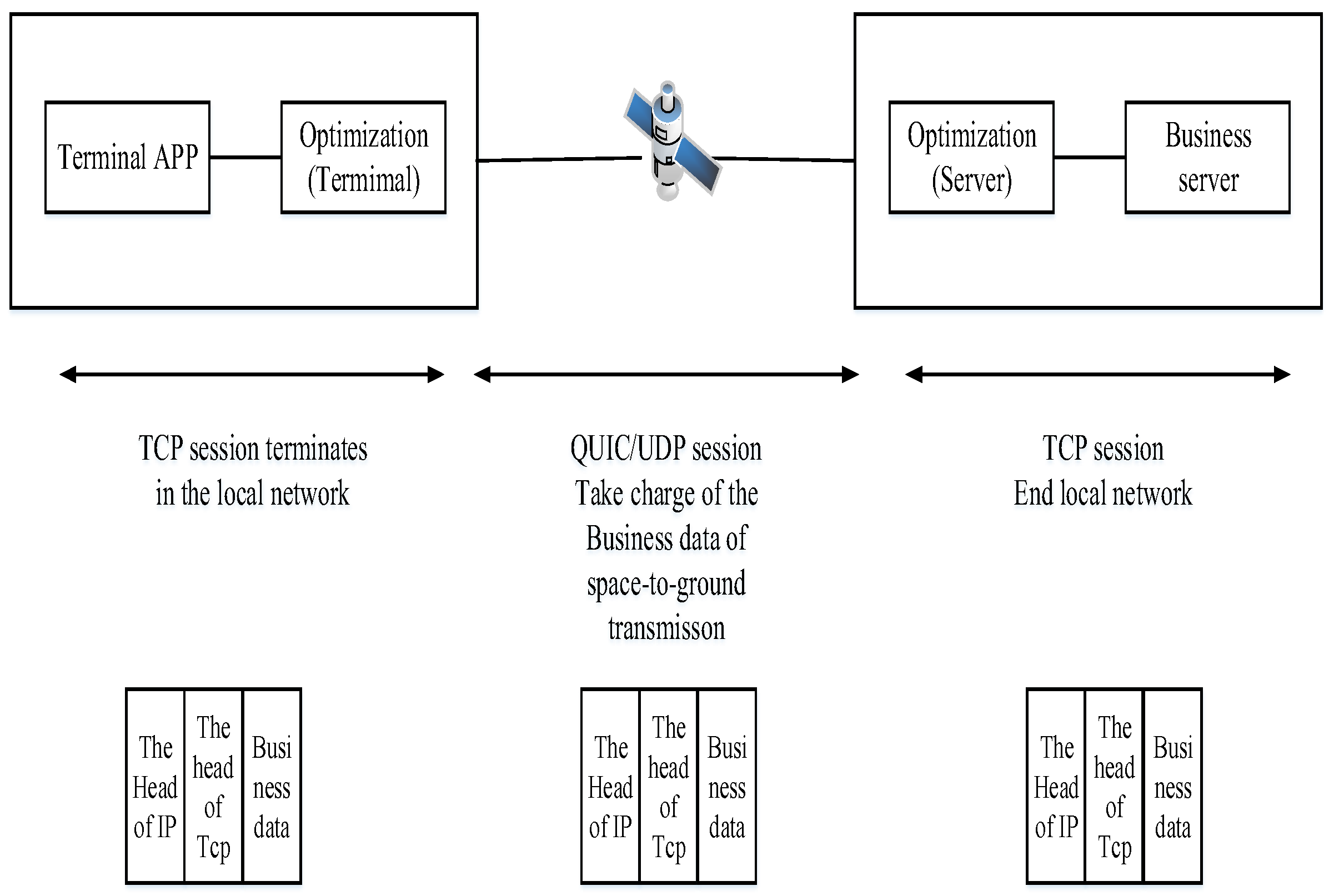
2.5. Lightweight TCP-QUIC Proxy Scheme (Scheme 5)
Scheme 5's design idea is to establish a QUIC/UDP transmission channel between the ground and in-orbit segments; break t he original long TCP session between the ground and in-orbit segments into two short TCP sessions [16], and connect and terminate them at the two local ends of the QUIC transmission channel. Compared with other schemes, this scheme can significantly improve the transmission rate without changing any underlying drivers, protocol stacks, and interfaces of the operating systems on both sides, and is transparent to upper-layer services, breaking through the original optimization framework and existing TCP optimization mechanisms.
The advantages of this scheme are:
- Flexible and efficient configuration: The lightweight proxy node is just ordinary software that can support different operating systems, and the installation/configuration/management is flexible and efficient.
- Improved transmission performance: The QUIC protocol is based on UDP and implements reliable transmission similar to TCP at the transport layer, with l ow latency and high concurrency, significantly improving data transmission speed and efficiency.
The disadvantages of this scheme is the Limited application layer optimization. The proxy scheme mainly optimizes at the transport layer, and for some scenarios that rely on specific application layer optimizations, such as specific HTTP protocol optimization and in-application caching strategies, it may not provide effective support, and the application performance improvement may not be obvious.
Considering the above improvements, the TCP session is terminated locally, completely solving the TCP window bottleneck problem, and the intermediate QUIC/UDP channel is optimized for high-speed transmission of business data. The disadvantage is that the application system's listening port needs to know the TCP proxy information in advance, but this can be solved through optimized design. Considering all factors, this Scheme is the optimal solution.
Figure 4.
Lightweight TCP-QUIC Proxy Scheme.
3. Lightweight TCP-QUIC Proxy Optimization Result
For the lightweight TCP-QUIC proxy optimization scheme, a prototype system of a network TCP transmission performance optimization system was developed. The FTP client and optimization system (client) on the left were deployed in one virtual machine, and the FTP server and optimization system (server) on the right were deployed in another virtual machine. The transmission link parameters between the two virtual machines were set as follows: the link bandwidth from the client to the server was 150Mbps, the delay was 270ms or 400ms, and the bit error rate was 1/106. The link bandwidth from the server to the client was 10Mbps, the delay was 270ms or 400ms, and the bit error rate was 1/106.
The hardware-in-the-loop experiment deployment was shown in Figure 5, including two physical hosts A and B. Host A ran the FTP client and TCP transmission optimization client software (prototype), which were interconnected through the local network to form a local TCP session; Host B ran the FTP server and TCP transmission optimization server software (prototype), which were also interconnected through the local network to form a local TCP session; the transmission optimization software of Host A and B were interconnected through the physical IP network to establish a high-speed QUIC transmission channel. In the above experimental network, the local network had no speed limit, no packet loss, and no delay, while the physical network card needed to be limited to simulate the satellite link.
To realistically simulate the satellite link, it is necessary to set the delay and packet loss on the receiving direction of both ends of A and B to simulate that the packet loss and delay occur on the satellite link rather than the local network; it is also necessary to set the bandwidth limit on the data sending of the physical network cards of both ends of AP to avoid occupying additional satellite link bandwidth.
It should be noted that the specific experimental para meter settings were slightly different according to the different file transmission directions, as follows.
1. When testing the FTP client to transfer files to the FTP server, the sending of the physical host A's network card was set to a speed limit of 150 Mbps, and the receiving is not limited. The sending of this NIC was not set with delay and packet loss, but the receiving was set with (one-way) delay of 270 or 400 ms and a loss rate of 0.2% (considering mainly ACK small packets). At the same time, the sending of the physical host B's network card (NIC) was set to a speed limit of 10 Mbps, and the receiving was not limited. The sending was this NIC is not set with delay and packet loss, but the receiving was set with (one-way) delay of 270 ms and a loss rate of 1.2% (considering data packets calculated according to MTU 1500 bytes). Under the above settings, we uploaded 512MB and 1024MB files 4 times each and recorded the experimental results.
2. When testing the FTP client to download files from the FTP server, we set the sending of the physical host A's network card NICA to a speed limit of 150 Mbps, and the receiving is not limited. The sending of NICA was not set with delay and packet loss, but the receiving was set with (one-way) delay of 270 or 400 ms and a loss rate of 1.2% (considering data packets calculated according to MTU 1500 bytes). At the same time, we set the sending of the physical host B's network card NICB to a speed limit of 10 Mbps, and the receiving was not limited. The sending of NICB was not set with delay and packet loss, but the receiving was set with (one-way) delay of 270 ms and a loss rate of 0.2% (considering mainly ACK small packets).
Under the above configuration requirements, the following four experimental scenarios were designed, and the experimental results were recorded.
**Scenario 1**: The physical link was set with a one-way delay of 270 ms, and the uplink transmitted data. The FTP client sent files, and the FTP server received data. The experimental data during the transmission process were tabulated in Table 1 and Table 2.
According to Table 1 and Table 2, the optimized downlink business transmission rate has been significantly improved, and the file transmission completion time has been significantly reduced.
**Scenario 2**: The physical link was set with a one-way delay of 270 ms, and the uplink transmitted data. The FTP server sent files, and the FTP client received data. The experimental data during the transmission process were tabulated in Table 3 and Table 4.
According to Table 3 and Table 4, the uplink service data transmission rate after optimization had been significantly improved, and the file transfer completion time had been significantly reduced.
In addition, according to the performance of the monitoring window during the experiment, after optimization, when the FTP client continuously uploaded files, the CPU (Intel 8550U, 1.8GHz) utilization rate at the sender increased from 5% when idle to 33%. When the CPU (Intel i9 - 9900k, 3.6GHz) was used at the sender, the utilization rate increased from 1% when idle to 10%. The data rate on the observed 150 Mbps bandwidth link was approximately 115 Mbps.
When the FTP client continuously downloaded files, the CPU (Intel 8550U, 1.8GHz) utilization rate at the receiver increased from 5% when idle to an average of 12%. When the CPU (Intel i9 - 9900k, 3.6GHz) was used, the utilization rate increased from 1% when idle to about 5%. The data rate on the observed 10Mbps bandwidth link was approximately 9.3 Mbps.
**Scenario 3**: The physical link was set with a one - way delay of 400 ms, and data was transmitted upstream. The FTP client sent files, and the FTP server received data. The experimental data during the transmission process were tabulated in Table 5 and Table 6.
According to Table 5 and Table 6, as the RTT increases (up to 800 ms), the optimized transmission rate decreased to some extent. However, the downlink service data rate still reached over 44 Mbps. Compared with before optimization, the downlink service transmission rate after optimization still had a significant increase, and the file transfer completion time was significantly reduced!
**Scenario 4**: The physical link was set with a one-way delay of 400 ms, and data was transmitted upstream. The FTP server sends files, and the FTP client receives data. The experimental data during the transmission process were tabulated in Table 7 and Table 8.
As can be seen from Table 7 and Table 8, as the RTT increased (up to 800 ms), the optimized transmission rate decreased to some extent. However, the uplink service data transmission rate after optimization still had a significant increase, and the file transfer completion time was significantly reduced.
The experimental results showed that the TCP transmission optimization system (prototype system) designed according to our proposed idea can greatly improve the service data transmission rate in both the uplink and downlink directions, with a very significant effect.
In the 150 Mbps downlink direction, the rate can be increased by more than 100 times, and in the 10 Mbps uplink direction, the rate can be increased by more than 7 times, far exceeding the usage requirements. Even if the round-trip delay increased from 540 ms to 800 ms, the optimized transmission results were still very significant. In addition, this technical solution was compatible with the original service interface, did not require modifying the network protocol stack and the underlying code of the operating system, was transparent to the service, and met the basic design requirements specified in the technical requirements document.
4. Summary of Technical Routes and Experimental Results of Each Scheme
Based on the scheme comparison and experimental verification results mentioned above, a summary table of the technical routes and experimental results of e ach scheme was presented, as shown in Table 9.
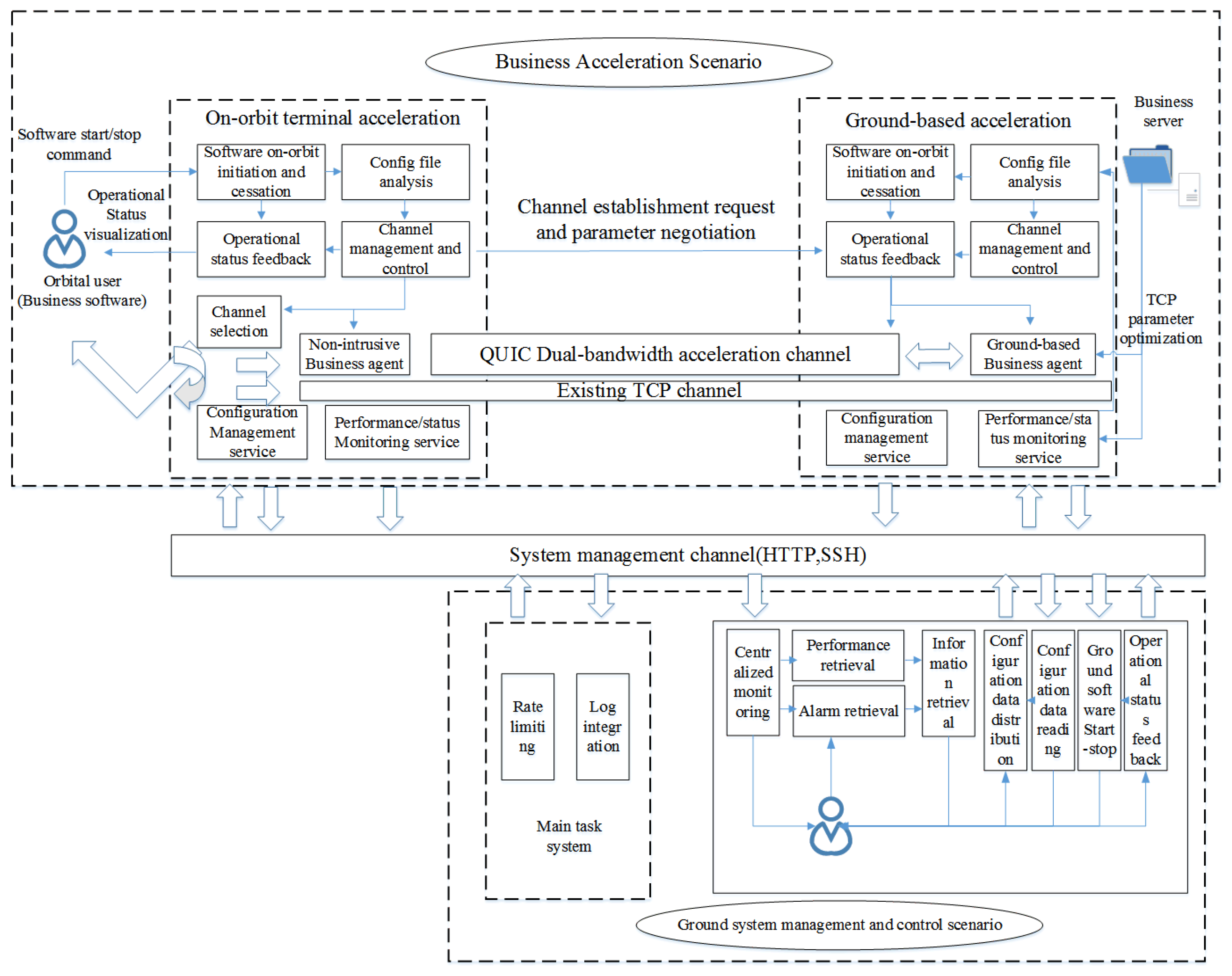
5. Business Acceleration Scenarios of the Lightweight TCP - QUlC Proxy Optimization Scheme
In the laboratory environment we established a ground-end and a simulated in-orbit end and designed two service channels: a QUIC dual - end acceleration channel and an existing TCP service channel. The QUIC dual-end acceleration channel was preferentially utilized for cross - orbit service transmission. In the event that this channel malfunctioned and was unable to support service transmission the system would automatica11y roll back to the original TCP service channel ensuring the smooth completion of the transmission service.
Figure 6.
Business Acceleration Scenario.
6. Analysis of the System Operating Environment
Currently, the operating environment of the lightweight TCP - QUIC proxy optimization system can support hardware platforms such as X86 - series hosts and microcomputers. It can run on domestic Kirin operating systems and Windows 7 64 - bit SP1 and above operating systems. In software design and implementation, mature technologies were adopted, and programming languages such as C, C++, and Java can be used. Due to the need for domestic substitution in recent years, the lightweight TCP - QUIC proxy optimization system for in-orbit satellite transmission needs to be deployed on domestic servers, and users also need to access through domestic terminals. Currently, mainstream domestic server/terminal chips include Loongson, Kunpeng, Phytium, and Shenwei. In the future, continuous research and system adaptation work with domestic chips need to be carried out to form an embedded domestic in-orbit satellite transmission optimization system. The advantages of domestic substitution are security and controllability, higher adaptability, improvement of local independent innovation capabilities, and mastering of core technical property rights. Disadvantages: From a technical perspective, currently, there is a gap between domestic products and international advanced levels in terms of performance, stability, and reliability. Domestic chips need to improve their computing power, and domestic software has compatibility issues. Domestic adaptation requires a large amount of resources for research and development, testing, and optimization. Adaptation involves multiple links and departments, with great coordination difficulties and low efficiency. From an ecological perspective, the application ecosystem of domestic products is relatively weak, and device compatibility is poor. From the perspectives of national security, industrial development, and technological innovation, the domestic substitution work will be studied and carried out as soon as possible.
7. Conclusions
This paper designed, compared and analyzed five mainstream transmission schemes for data transmission between the in-orbit end (high - orbit satellite) and the ground end (ground server): the double-size lightweight TCP parameter optimization scheme, the double-size heavyweight TCP kernel optimization scheme, the ground side single-side heavyweight TCP kernel optimization scheme, the heavyweight tunnel optimization scheme, and the lightweight TCP - QUIC proxy optimization scheme. Finally, only the lightweight TCP - QUIC proxy optimization scheme can meet the usage requirements. The results of the semi-physical simulation experiment using the established prototype system showed that after optimization, in the 150 Mbps downlink direction, the rate can be increased by more than 100 times, and in the 10 Mbps uplink direction, the rate can be increased by more than 7 times, far exceeding the usage requirements.
Therefore, the lightweight TCP - QUIC proxy optimization scheme can be used as a highly competitive standard technical scheme for high - orbit satellite data transmission in China in the future, and it will play an important application role.
Author Contributions
Conceptualization, W.D.; methodology T.S.; validation, B.W.; formal analysis, T.S.; investigation, T.S., Z.L.; resources, W.D.; data curation, B.W.; writing—original draft preparation, T.S.; writing—review and editing, Z.L.; visualization, T.S.; supervision, W.D.; project administration, T.S.; funding acquisition, W.D. All authors have read and agreed to the published version of the manuscript.
Funding
This research received no external funding.
Data Availability Statement
Data is unavailable due to privacy or ethical restrictions.
Conflicts of Interest
The authors declare no conflicts of interest.
Abbreviations
The following abbreviations are used in this manuscript:
| CPU | Central Processing Unit |
| E2E | End-to-End |
| FEC | Forward Err or Correction |
| FTP | File Transfer Protocol |
| NIC | Network Identification Card |
| QUIC | Quick UDP Internet Connections |
| RTT | Round Trip Time |
| TCP | Transmission Control Protocol |
| UDP | User Datagram Protocol |
| VPN | Virtual Private Network |
References
- Carlo Caini, Rosario Firrincieli, Daniele Lacamera. PEPsal: a Performance Enhancing Proxy for TCP satellite connections [C], Proc. of IEEE VTC’06 spring, Melbourne, May 2006, 22, B9–B16.
- Zeng, B.; Li, Z.; Xu, F. TCP Proxy for Satellite Networks. Journal of Software 2007, 18, 1695–1704. [Google Scholar] [CrossRef]
- Velenis, D.; Kalogeras, D.; Maglaris, B. SaTPEP: A TCP Performance Enhancing Proxy for Satellite Links Published in NETWORKING 19 May 2002 Computer Science, Engineering: 1233-1238.
- Wang, H.; Wang, L.; Wu, Z. Research on TCP Transmission Performance for Satellite Networks. Communications Technology 2008, 41, 145–149. [Google Scholar]
- Hou, X. Research on the Improvement of the TCP Vegas Algorithm Applicable to Satellite Networks. Science& Technology Vision 2015, 1, 119. [Google Scholar]
- Cao, X.; Zhang, X. SaTCP: Link-layer informed TCP adaptation for highly dynamic LEO satellite networks[C],IEEE INFOCOM, Hoboken, New Jersey, USA, 2023.
- Stevens, W. TCP/IP Illustrated, Volume I: The Protocols[M]. Beijing: Tsinghua University Press, 1994.
- Sibo Pan, Ruifeng Gao, Yingdong Hu, Ye Li. TCP Performance in Satellite Backhauling for Maritime Communications: A ns-3 Study[C], 14th International Conference on Wireless Communications and Signal Processing (WCSP), Nanjing, November 2022: 877-882.
- Red Hat Enterprise. Chapter 31. Tuning the network performance, in Monitoring and managing system status and performance: [M], 2024: 244-285.
- Jerry Chu. Tuning TCP Parameters for the 21st Century [C], 75th Internet Engineering Task Force Confernce, Stockholm , July 2009.
- Yuchung Cheng, Neal Cardwell, Making Linux TCP Fast[J], Netdev Conference, 2023.
- ExtraHop. Network Inc. Optimizing TCP: Nagle’s Algorithm and Beyond [R],2016https://assets.extrahop.com/whitepapers/T CP-Optimization-Guide-by-ExtraHop.pdf.
- Lin Lixiang, Liu Xudong, Liu Shaoteng, Xu Yuedong. Review of the Application of Forward Error Correction Coding in Network Transmission Protocols. Computer Science 2022, 49, 292–303. [Google Scholar]
- Esma Yildirim, Dengpan Yin, Tevfik Kosar, Balancing TCP Buffer vs Parallel Streams in Application Level Throughput Optimization[C], DADC'09, Munich, Germany. June 2009, 21–30.
- Sanadidi, M.Y.; Gerla, M.; Stepanek, J. On-board satellite ‘Split TCP’ Proxy. IEEE Journal on Selected Areas in Communications 2004, 22, 362–370. [Google Scholar]
Figure 1.
Double-Side TCP Lightweight Parameter Optimization.
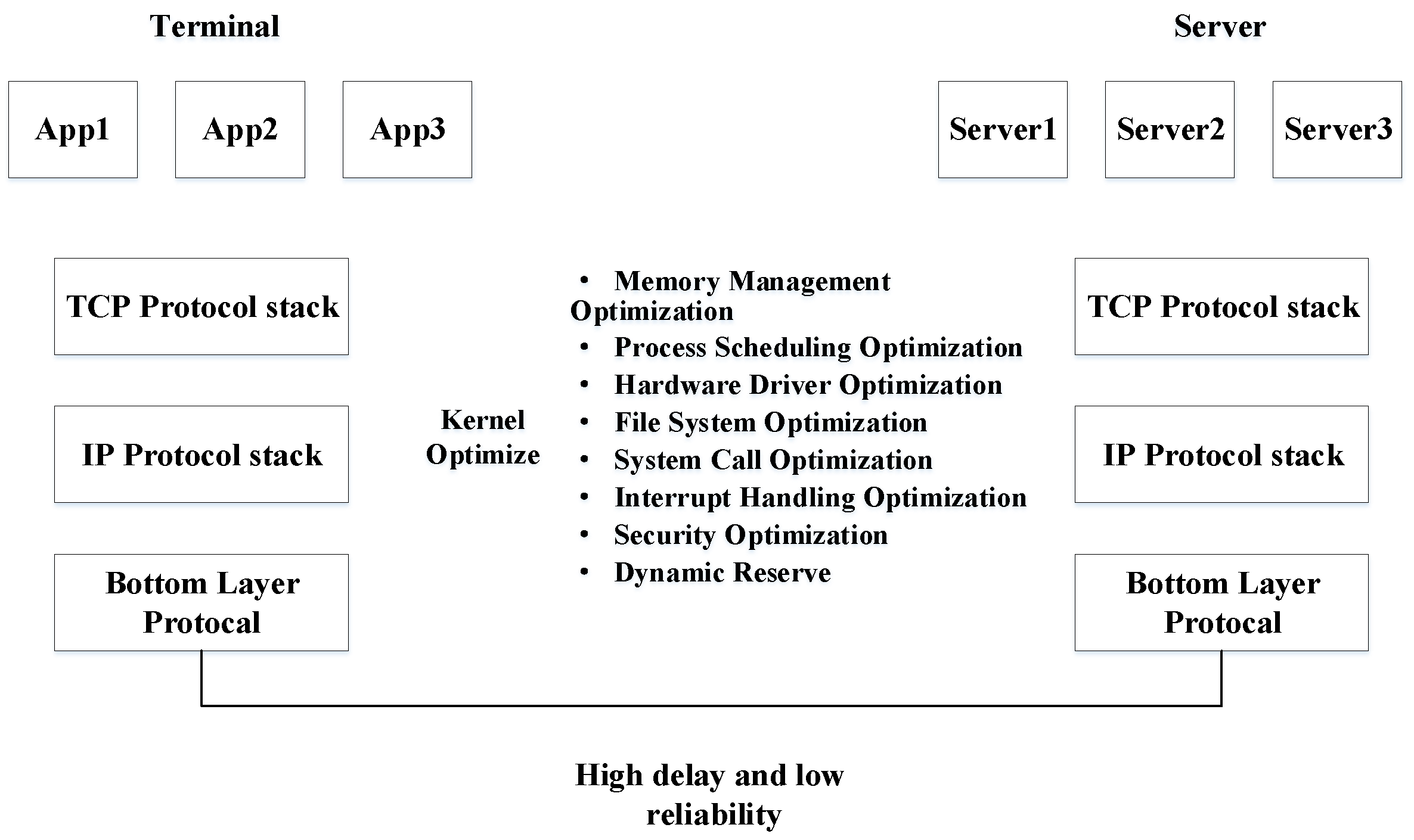
Figure 2.
Double-Side TCP Heavyweight Core Optimization Scheme.
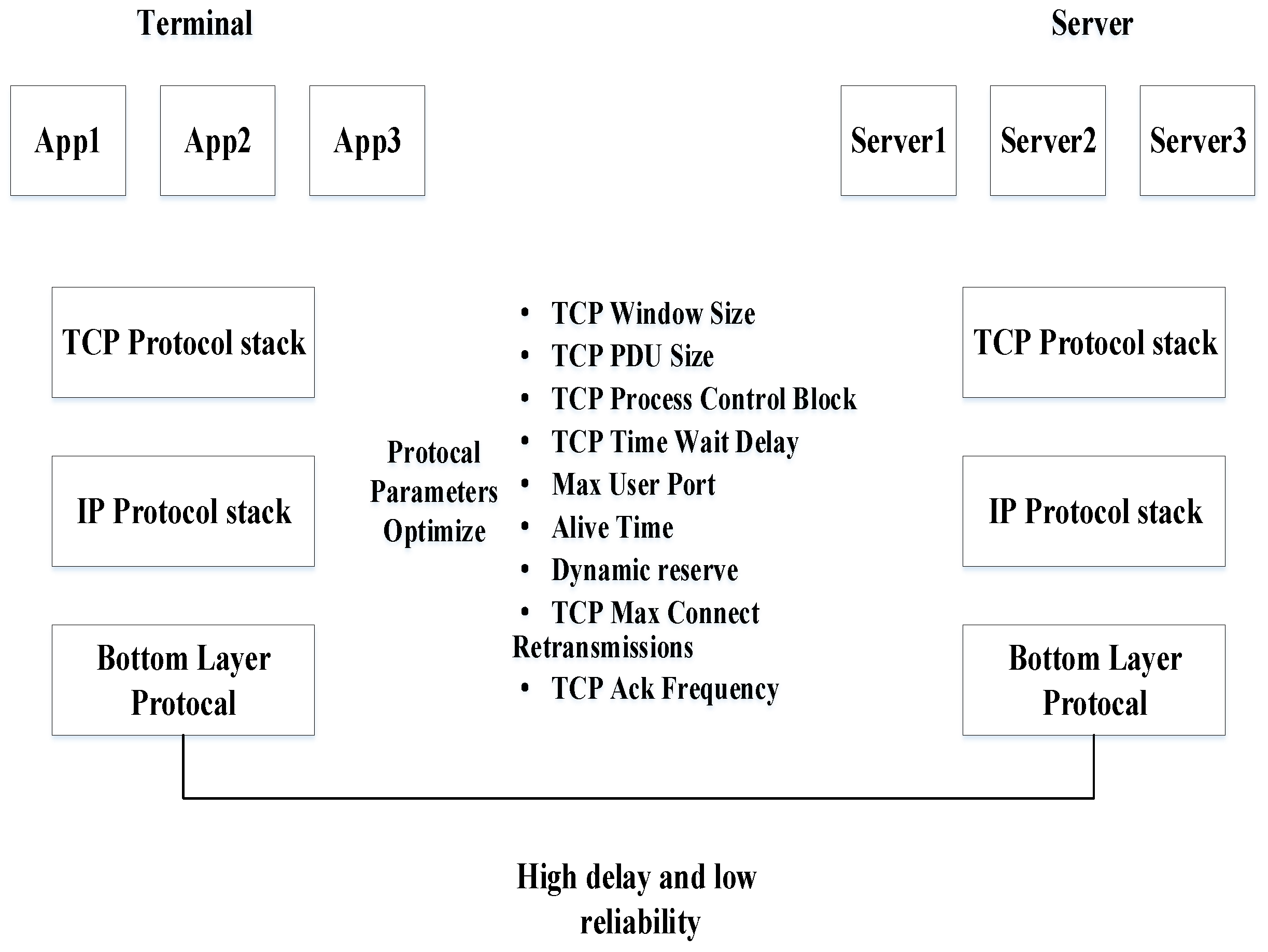
Figure 3.
Single-Side TCP Heavyweight Core Optimization Scheme.
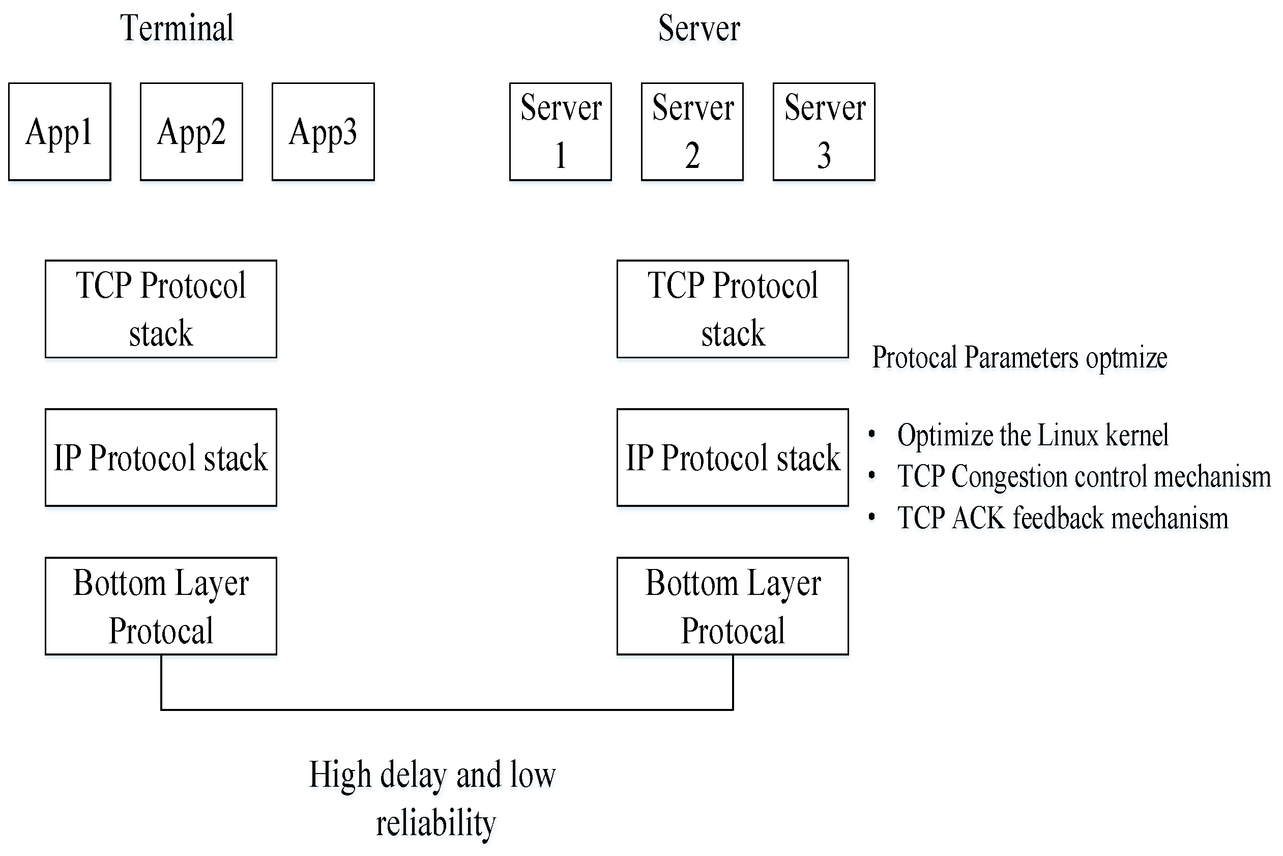
Figure 5.
Scheme 5 test bed configuration.
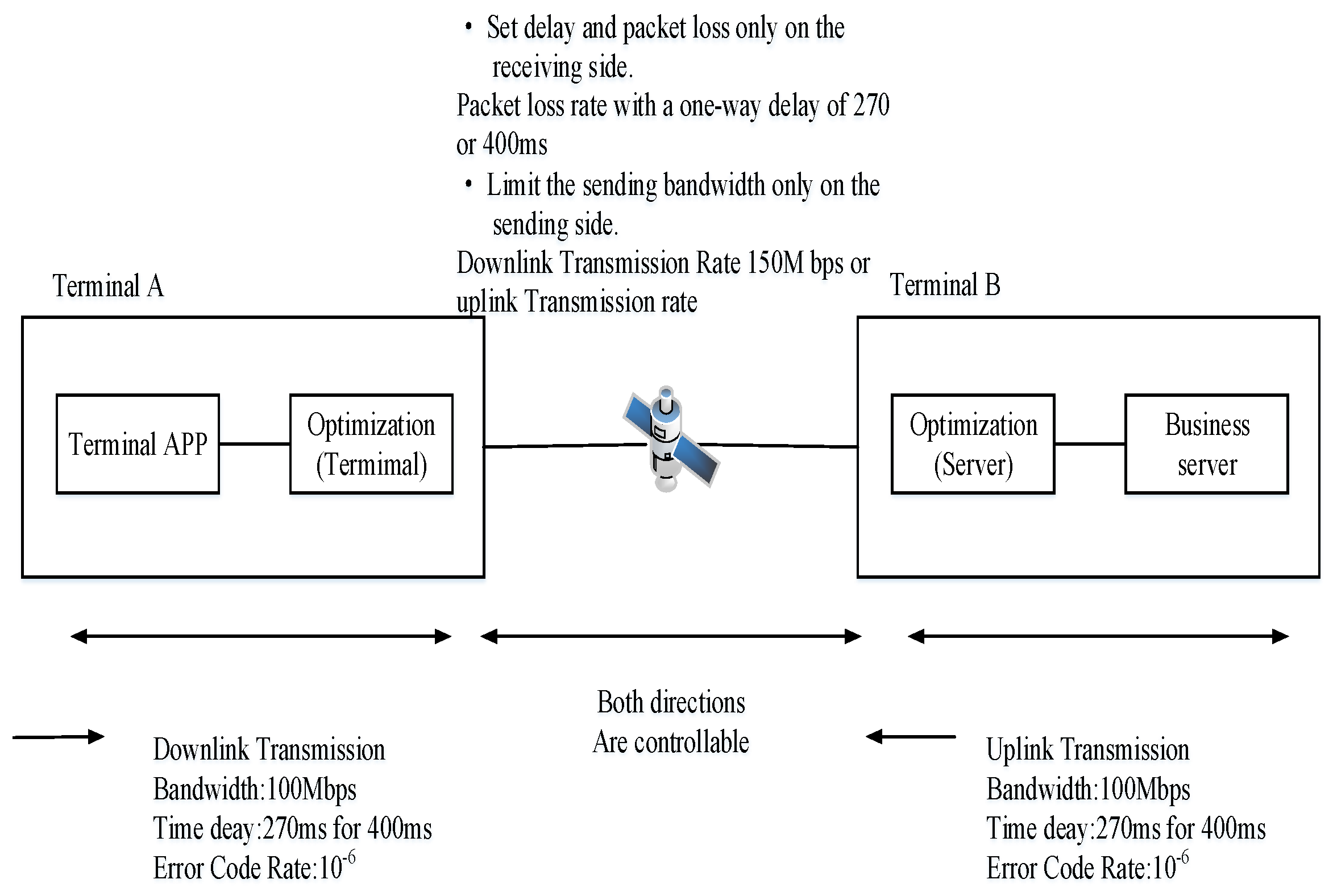

Table 1.
Business transmission rate during downlink transmission (Scenario 1).
| File Size | Optimized Rate (Mbps) | Pre-Optimized Rate (Mbps) | |||
|---|---|---|---|---|---|
| 1 | 2 | 3 | 4 | ||
| 512MB | 79 | 78 | 75 | 78 | ≈0.6 |
| 1024MB | 78 | 77 | 78 | 78 | ≈0.6 |
Table 2.
File transmission time during downlink transmission (Scenario 1).
| File Size | Optimized Transfer Time (s) | Pre-Optimized Transfer Time (s) | |||
|---|---|---|---|---|---|
| 1 | 2 | 3 | 4 | ||
| 512MB | 75 | 72 | 74 | 73 | ≈7200 |
| 1024MB | 118 | 124 | 123 | 123 | ≈1440 |
Table 3.
Business transmission rate during downlink transmission (Scenario 2).
| File Size | Optimized Rate (Mbps) | Pre-Optimized Rate (Mbps) | |||
|---|---|---|---|---|---|
| 1 | 2 | 3 | 4 | ||
| 8.6MB | 7.91 | 7.97 | 8.21 | 7.86 | ≈1.2 |
| 74MB | 8.36 | 8.34 | 8.34 | 8.34 | ≈1.2 |
Table 4.
File transmission time during downlink transmission (Scenario 2).
| File Size | Optimized Transfer Time (s) | Pre-Optimized Transfer Time (s) | |||
|---|---|---|---|---|---|
| 1 | 2 | 3 | 4 | ||
| 512MB | 75 | 72 | 74 | 73 | ≈7200 |
| 1024MB | 118 | 124 | 123 | 123 | ≈1440 |
Table 5.
Business transmission rate during downlink transmission (Scenario 3).
| File Size | Optimized Rate (Mbps) | Pre-Optimized Rate (Mbps) | |||
|---|---|---|---|---|---|
| 1 | 2 | 3 | 4 | ||
| 512MB | 46 | 44 | 45 | 49 | ≈0.42 |
| 1024MB | 45 | 46 | 45 | 48 | ≈0.42 |
Table 6.
File transmission time during downlink transmission (Scenario 3).
| File Size | Optimized Transfer Time (s) | Pre-Optimized Transfer Time (s) | |||
|---|---|---|---|---|---|
| 1 | 2 | 3 | 4 | ||
| 512MB | 91 | 93 | 89 | 92 | ≈10200 |
| 1024MB | 180 | 181 | 178 | 179 | ≈21000 |
Table 7.
Business transmission rate during downlink transmission (Scenario 4).
| File Size | Optimized Rate (Mbps) | Pre-Optimized Rate (Mbps) | |||
|---|---|---|---|---|---|
| 1 | 2 | 3 | 4 | ||
| 8.6MB | 7.07 | 7.12 | 7.08 | 7.10 | ≈0.72 |
| 74MB | 7.64 | 7.65 | 7.63 | 7.68 | ≈0.72 |
Table 8.
File transmission time during downlink transmission (Scenario 4).
| File Size | Optimized Transfer Time (s) | Pre-Optimized Transfer Time (s) | |||
|---|---|---|---|---|---|
| 1 | 2 | 3 | 4 | ||
| 8.6MB | 10 | 8 | 10 | 9 | ≈89 |
| 74MB | 71 | 73 | 71 | 72 | ≈760 |
Table 9.
Summary Table of Technical Routes and Experimental Results of Each Scheme.
| Scheme Number | Scheme Name | Technical Route | Experimental Result |
|---|---|---|---|
| 1 | Double-Side TCP Lightweight Parameter Optimization Scheme | Only by adjusting the socket interface parameters of the TCP stack that can be adjusted in the existing operating systems at the in-orbit and ground ends to optimize the two-way TCP transmission performance | The optimization effect of the lightweight optimization scheme is very limited and far from meeting the required transmission rate in the design |
| 2 | Double-Side TCP Heavyweight Core Optimization Scheme | Implements a new transmission control protocol that is compatible with the TCP interface in the operating system kernels at both the ground and on orbit ends to replace the traditional TCP transmission mechanism | If the Windows kernel is used at the on - orbit end, the logic is complex and the technical documentation is not open, resulting in extremely high actual design and development difficulties. If the Linux kernel is used at the in-orbit end, the actual transmission rate of the 100 Mbps uplink bandwidth can reach 20 - 30 Mbps, but the unknown risks brought by modifying the operating system cannot be controlled. |
| 3 | Ground-Side Single-Side TCP Heavyweight Core Optimization Scheme | Only deeply optimizes the TCP stack on the ground - side, without modifying the stack on the space side. This includes modifying/replacing the TCP congestion control algorithm to improve the space to ground transmission rate | Easy to implement: deep optimization on the ground side and no need to modify the space side. However, the experimental results showed that the actual transmission rate on a 10 Mbps link can be increased to a certain extent, reaching about 4Mbps, which does not meet the design requirements; the transmission rate achieved on a 100 Mbps link is about 6 Mbps, which also does not meet the requirements. |
| 4 | Heavyweight UDP/ FEC Tunnel Optimization Scheme |
Establish a VPN tunnel based on UDP/FEC between the ground and on orbit ends. The original TCP service data is transparently transmitted through this tunnel | Although FEC can reduce packet loss, UDP itself has no congestion control. However, the congestion control mechanism of the end to end TCP flow is still restricted by the large RTT, and the channel bandwidth cannot be fully utilized. The experimental results show that the actual transmission rate increase on 10/100 Mbps links is less than 1 Mbps, far from meeting the requirements |
| 5 | Lightweight TCP-Q UIC Proxy Scheme | Establish a QUIC/UDP transmission channel between the ground and on orbit ends; break the original long distance TCP sessions at the ground and on orbit ends into two short distance TCP sessions, which are respectively connected to and terminated at the two local ends of the QUIC transmission channel | Advantages: The TCP session is terminated locally, with a small RTT and no window bottleneck; the QUIC/UDP transmission channel is specially optimized for high latency/bandwidth/loss rate scenarios, so the channel bandwidth can be fully utilized. The experimental results show that the actual rate on a 10Mbps bandwidth can reach 8.5Mbps; the actual rate on a 100 Mbps bandwidth can be as high as 72.5 Mbps |
Disclaimer/Publisher’s Note: The statements, opinions and data contained in all publications are solely those of the individual author(s) and contributor(s) and not of MDPI and/or the editor(s). MDPI and/or the editor(s) disclaim responsibility for any injury to people or property resulting from any ideas, methods, instructions or products referred to in the content. |
© 2025 by the authors. Licensee MDPI, Basel, Switzerland. This article is an open access article distributed under the terms and conditions of the Creative Commons Attribution (CC BY) license (http://creativecommons.org/licenses/by/4.0/).
Copyright: This open access article is published under a Creative Commons CC BY 4.0 license, which permit the free download, distribution, and reuse, provided that the author and preprint are cited in any reuse.


