
Submitted:
11 August 2025
Posted:
13 August 2025
You are already at the latest version
Abstract
A novel sensorless rotor position and speed estimator is presented in this study. The method is based on the measurement of the current response to conventional space-vector pulse width modulated voltages (SV-PWM) for PMSM drives applications. Model-Reference Adaptive Systems (MRAS) estimators are often used for sensorless speed estimation. A MRAS typically uses two models: the reference model (voltage model) and the adaptive model (current model). The voltage model in flux-based MRAS uses integration of stator voltages to calculate the stator flux. The pure integrator is usually replaced by a low pass filter; however, this results in phase errors at low frequencies. The position is estimated using oversampling and averaging over a switching SV-PWM cycle, eliminating the need for integrators. Extensive experimental tests are presented to evaluate the performance of the proposed estimator. The results of the experiments demonstrate good performance at various speeds and under various load circumstances, in both motoring and regenerating mode. The proposed method also shows robustness to changes in motor parameters.
Keywords:
model reference adaptive system (MRAS)
; PMSM
; sensorless
; SV-PWM
; speed estimation
1. Introduction
The use of permanent magnet synchronous machines (PMSMs) is widespread in both industrial and high-performance applications, such as electric vehicles traction, due to their high efficiency, high power density, and simple structure [1]. PMSMs are typically controlled using field-oriented control, which offers high accuracy and rapid dynamic response [2]. Accurate rotor position measurement is essential for effective field orientation, and this is usually achieved through encoders or resolvers. However, in low-cost applications, the additional expenses related to position sensors—including size, weight, wiring, and associated electronic components—are often undesirable. This has led to a growing interest in sensorless control systems. Additionally, in high-performance applications where reliability is critical, such as in electric vehicle traction motors, resolvers are commonly employed. Nonetheless, sensorless estimation is frequently implemented as a backup solution to enhance drive reliability in the event of sensor failure. The literature presents a wide variety of methods for sensorless operation of PMSMs.
Several techniques for sensorless control have been proposed based on sliding modes (SM), Fuzzy Logic, artificial neural networks (ANNs), full-order flux observers, Extended Kalman filter (EKF), saliency and signal injection, and model reference adaptive systems (MRASs). Although SM method is robust against parameter variations, it suffers from chattering problem and heavy calculation demands [3]. Fuzzy Logic [4] and ANN-based methods [5] are popular, but they rely on complex computations and large memory requirements. The full-order flux observers are well-known model-based methods utilized for sensorless controls. [6] proposed a full-order flux observer to improve performance and robustness, but it experiences instability at low speeds due to high feedback gains. In response, [7] developed a full-order flux observer to address this instability, but this solution increases control complexity and requires careful tuning of feedback gains based on operating conditions. EKF-based methods [8] are robust to noise in the system, but they are computation-intensive. Signal injection methods [9] perform satisfactorily at zero and very low speed and are less sensitive to the motor parameters, but can generate additional acoustic noises and oscillations in torque and speed and require saliency in the machine.
At medium and high speeds, the rotor angle can be estimated from back-emf based methods [10], either by directly measuring the third harmonic of the back emf, which requires access to the neutral point of the motor, or from a voltage model of the motor, which is sensitive to parameter errors. MRAS-based methods are estimators belonging to the general class of back-EMF based methods [11]. MRAS based methods have proven popular due to their simplicity of implementation [12]. In [13], the comparison of MRAS, SM, and EKF highlights key performance differences. MRAS leads with a steady state and transient speed error of 0.42%, excellent resistance robustness, and 0.8% error under load changes. In contrast, SM shows higher speed errors (2% steady state, 4.2% transient) and poor load change robustness (10.4% error). EKF has a steady state error of 0.5% but lacks robustness, particularly to inductance changes, with a load change error of 4.2%. Power-based MRAS methods have been demonstrated to have good performance, but they can be unstable in certain operating points [14]. Instability of MRAS-based methods in certain operating conditions has been addressed recently in [15]. It has been demonstrated that flux-based MRAS estimators can perform excellently down to 5% of rated speed [16]. However, a significant limitation of this approach is the presence of a pure integrator in the reference model. The integrator has infinite gain at zero frequency and, therefore, can potentially amplify small offsets and initial conditions. To address this issue, one common solution is to replace the pure integrators with low-pass filters (LPF). However, LPFs introduce additional phase delays, which leads to angle estimation errors at low speeds.
In [17], programmable Low-Pass Filters are utilized for stator flux estimation to mitigate the issue of phase delay. However, reversing speeds can cause instability. A modified integration algorithm was presented in [18] to avoid problems in speed reversals. However, the method is sensitive to parameters. In [19], high-pass filters are employed in both voltage and current models to mitigate integrator issues. but the computational complexity of the fuzzy controller is the main drawback of this scheme, and it consumes time and effort to tune the three scaling factors. [20] proposed a solution to the problem of integration drift, offering advantages such as simplicity, fast response, and the absence of frequency-dependent phase shift in steady states. However, this method has potential limitations due to the open-loop nature of the estimator, including sensitivity to input signal quality, and operational conditions. Recently, [21] introduced a fourth-order generalized integrator with frequency-locked loop (FOGI-FLL) flux observer to eliminate the DC offset and harmonics in the estimated EMF, contributing to improving the position estimation. However, complexity is increased.
In this paper, a new flux-based MRAS is presented. Unlike the classical flux-based method, which relies on the voltage model integration, the proposed estimation technique is integrator-independent. This method employs a method similar to that presented in [22] where the q-axis voltage equation of a PMSM was used to derive an estimation of PM flux linkage. This paper uses a similar method based on the d-axis voltage equation to derive the reference model for the MRAS speed and angle estimator. Through extensive experimental tests in various operating conditions the accuracy of position and speed estimations is demonstrated as well as the good accuracy under parameters uncertainties. Performance at low speeds is improved compared to classical method. Furthermore, stability across all four operating quadrants is demonstrated.
2. Control and Estimation
2.1. Machine Model
The voltage equations of a PMSM represented in the rotating dq-reference frame are expressed as:
where , , , and are dq-axis voltages and currents, respectively; , , are the dq-axis inductances, is the stator resistance, is the rotor speed, and is the rotor PM flux linkage.
2.2. Classical Flux-Based MRAS Speed Estimator
The classical MRAS speed estimation compares estimated stator flux linkage from integrating back emf (3), with stator flux linkage from magnet flux and current (4).
Equation (4) is transformed to the stationary reference frame by using the Clarke to Park transform as:
where , , , are the estimated flux components for the voltage and current models, respectively; , , , are voltages and currents in the stationary α, β reference frame; , are the currents in the estimated dq-rotating frame, and is the estimated rotor position.
The estimated speed is obtained by minimising the angle error between the two stator flux linkages vectors estimations. This can be achieved by calculating the magnitude of the cross product of the two estimated fluxes as:
The error in (6) is then fed to a PI controller to produce an estimation of rotor speed which is integrated to obtain the estimated position. As shown in Figure 1, the position is fed back to the current model to drive the error to zero.
2.3. Novel PWM-Based Speed Estimator
Equation (1) can be represented in the estimated rotating dq-reference frame as:
where , , and are the estimated dq-axis voltages and currents, respectively; is the estimated rotor speed, and is the flux on the estimated q-axis.
Figure. 2 shows the simulation of three PWM gate signals, each with a period of 500μs controlling the top three transistors in a two-stage voltage source inverter. It also shows the corresponding and , sampled at 50μs.
Assuming that … (shown in Figure 2) are the time instants at which a different voltage vector is applied and is constant during one switching period, the equation (7) is discretized with a sampling time . The resultant relationships between two adjacent sampling points are given as:
where n is the integer number of sampling points in one switching cycle, is the starting point of the PWM period, and is the last sampling point in the period.
The derivative term can be approximated by:
Multiplying the n − 1 equations by and adding each equation to the next, it yields:
where , where is the switching frequency, k = 0,1 … n – 2, and is the th equation.
According to [22], the sum is equivalent to the average PWM voltage:
where , , , and are the results of the switching vectors being transformed from αβ -reference frame to estimated dq- rotating reference frame.
As the switching period consists of two symmetrical switching combinations, it can be easily verified that:
Therefore, after rearranging (11) to get now becomes:
The rotating voltage reference vector’s location on the space vector diagram is used to calculate the average PWM voltage at the beginning of a PWM switching period, hence the reference voltage on αβ stationary frame (, ) should take the form of a rotating space vector.
The actual reference magnet fluxes in the real dq-rotating frame, are represented as and 0. While, the estimated flux on the estimated -axis, will be proportional to the sine of the angle estimation error, Figure 3 shows the simulation result of . The vector product ϵ of the flux components, shown in (16), is fed into a PI controller, which produces the estimated speed. Finally, the integration of the speed gives the estimated position, as shown in Figure 4.
For vector controlled PMSM drive ( ), the equation (15) can be simplified as:
3. Experimental Setups
The experimental setup (Figure 5) consists of two identical 2.1 kW PMSMs, one dynamometer is connected to a three-phase two-levels inverter (Semikron IGBT module stack) and controlled by a Speedgoat real-time controller. The second Drive Unit is controlled by a Nidec Unidrive 700M drive. The two motors can be controlled in either speed or torque modes. The motor parameters are presented in Table 1. A 4096 counts/rev resolution quadrature encoder is used to measure the rotor position for verification purposes, and two TA189 current sensors are used for current phase measurements. Position and currents are sampled at 80μs. The inverter switching frequency is set to 3.125 kHz with a dead time of 0.5μs. The control strategy (FOC), illustrated in Figure 6 (the switch box is performed manually to compare the performance of the two methods), is executed at a sampling frequency of 80 μs using the Speedgoat real-time controller, which is fully integrated with MATLAB/Simulink. The estimation algorithm is executed using a MATLAB function block, and is triggered at the beginning of each PWM switching period. The ratio between the sampling frequency and the switching frequency is chosen to ensure that the number of sampling points, and thus the number of equations, within a switching period is an integer, while also ensuring sufficiently accurate results without excessive computational burden. The command voltages generated by the controller are used in place of the measured voltages. Therefore, inverter nonlinearity and dead time effects are not taken into account. The PI controller gains of the novel method are set to 500 and 2000, whereas the classical method employs gains of 200 and 2000. The trial-and-error approach is employed for tuning the gains. The current and speed control loop bandwidths are 318 Hz and 2 Hz respectively. A first-order LPF with a 3 Hz cut-off frequency is used in the classical method instead of the integrator to minimize drift and initial condition problems. However, it causes a position error of about 0.3 rad at 3 Hz. The trade-off between angle error and filtering is used as a design criterion.
4. Experimental Results
To evaluate the comparative performance of the proposed estimator and the classical flux-based MRAS scheme, extensive tests are performed in FOC under position sensorless operation. Both estimators’ performances are evaluated under the condition ( ) and with the same sampling time and switching frequency. As shown in Figure 7, a rotating signal injection method is used for zero speed starting as back-EMF is unobservable at zero speed for both the conventional and the proposed method. The injection frequency and amplitude of the injected voltage are 40 volts and 400 Hz respectively. Figure 6 shows that the drive operates smoothly during the gradual transitioning from injection method to the proposed method at 3 s. The position error by the injection method is driven to zero once the proposed method is activated as shown in Figure 7(b).
In Figure 8 and Figure 9, the performance of the novel and the classical methods are tested at low speeds with no load. From Figure 8(a) and Figure 9(a), it clearly shown that the speed oscillation is higher for the classical method compared to the novel method. Moreover, Figure 8(b) shows that as the speed decreases, the position accuracy in the steady period is nearly not affected in the proposed method, but the error increases in the classical MRAS until it fails at a speed of 10 rad/s as shown in Figure 9(b). The loss of control occurs because the estimated currents and deviate from their reference’s values and . This deviation occurs as the position error increases significantly. This is clearly noticed from Figure 8(d) and Figure 9(d) which show the phase currents for the two methods. It is evident from Figure 8(d) that the phase currents are not affected when switching from sensored mode to sensorless mode at 5s using the novel method, and the current decreases as the speed decreases. In contrast, the classical method produces larger currents due to a higher position error.
Both methods are tested in motoring and regenerative modes, as illustrated in Figure 10 and Figure 11, respectively. Initially, the reference speed is set to 50 rad/s with 20% of the rated torque applied, which is then increased to 40% of the rated torque. In motoring mode (Figure 10), it is clear that both the speed error and the position error during the steady state are smaller for the new method compared to the classical method. However, during the transient period, both speed and position errors generated by the new method are slightly higher than those produced by the classical method. The performance of the new method can be enhanced beyond that of the classical method during the transient period. This can be achieved by further tuning the PI gain of the estimator used in the new method. In regenerative mode (Figure 11), the classical method shows a higher speed error than the new method in both steady state and transient periods. Concerning position error, it is evident that as the load increases, nearly +0.05 rad is added to the error for every 20% increase in rated torque for both methods, as illustrated in Figure 11b,d.
Figure 12 shows the performance of the classical MRAS-based method at switching frequencies of 3.125 kHz and 6,25 kHz with a sampling time of 80 μs. The reference speed is initially set to 20 rad/s and then increased to 50 rad/s under no load conditions. The results indicate that there is only a minimal difference between the estimated speed and position error obtained using higher switching frequencies compared to lower switching frequencies.
To test the proposed scheme’s robustness against motor parameter variations and compare it with the classical method, two experimental tests have been carried out. In the first test, (Figure 13), the sensorless mode occurs at 2s and a change of 50% is applied to the stator resistance in the estimator models at 5s, then further increased to 100% at 8s. In the second test, (Figure 14), Lq in the estimator models changes by 20% at 5s, followed by an increase to 40% at 8s. It can be observed that the novel method shows robustness against motor parameter variations. This can be noted by comparing both the speed error and the position error produced by the novel method before and after the changes, as shown in Figure 13 and Figure 14. They show that both the position error and speed error are not affected. In contrast, in the classical method, the speed oscillation (speed error) increases as the resistance rises, though it is less sensitive to changes in Lq. It is clear from (3) that the stator flux linkage, obtained from stator voltages integration is dependent on the value of stator resistance. The proposed method, instead, is based on the estimation of the q-axis magnet flux which is independent of the stator resistance as given by (17) Therefore, we can conclude that the proposed method is, in principle, insensitive to stator resistance.
The performance of the novel method is also tested for ≠0 to investigate the effect of cancelling the voltage terms and in (7) on the position accuracy. Figure 15 shows the position error resulting from setting the d-axis current reference to nonzero values. In the test, the d-axis current reference is set to 0.5 A and 1 A at 7s and 10s respectively. The implementation of equation (17) shows that the accuracy of the position experiences only a slight decrease compared to the compensated error arising from the use of equation (15), where all voltage terms are fully considered. The current measurements can be affected by switching ringing noise. To address this, a 100kHz bandwidth low-pass filter has been implemented to filter high frequency switching noise without affecting the estimation bandwidth.
5. Conclusion
In this paper, a novel flux-based MRAS speed estimator has been proposed for sensorless control of PMSM drives. The method uses oversampling of PWM voltages and currents during a switching cycle. The new method is proved to perform better than the classical MRAS method, with smaller position errors in most operating conditions. Unlike the classical flux-based MRAS method, the position accuracy is not affected in the novel method at low speeds due to the lack of integrator. The proposed method is also shown to be less sensitive to parameters variation. Compensations for the inverter nonlinearity and a dead-time effects can be employed in further research to reduce speed oscillation at very low speeds. It is also recommended to extensively test the performance of this method on PM machines operating in the flux-weakening region, where ≠0.
Author Contributions
Conceptualization, A.G.; methodology, S.S.; software, S.S.; validation, S.S.; formal analysis, S.S.; investigation, S.S.; resources, A.G.; data curation, S.S.; writing—original draft preparation, S.S.; writing—review and editing, A.G.; visualization, S.S.; supervision, A.G.; project administration, A.G. All authors have read and agreed to the published version of the manuscript.
Funding
This research was funded by the Libyan embassy in London, UK during the PhD.
Institutional Review Board Statement
Not applicable.
Informed Consent Statement
Not applicable.
Data Availability Statement
Data sharing not applicable.
Conflicts of Interest
The authors declare no conflict of interest.
References
- Krishnan, R., Permanent Magnet Synchronous and Brushless DC Motor Drives. 2017: Cleveland, OH, USA.
- Bose, B.K, Power Electronics and Variable Frequency Drives. 1996, Wiley: USA.
- Zuo, Y. Lai, C. Iyer, K.L.V. A Review of Sliding Mode Observer Based Sensorless Control Methods for PMSM Drive. IEEE Trans. Power Electron. 2023, 38, 11352–11367.
- Mohan Krishna, S. and J.L. Febin Daya, MRAS speed estimator with fuzzy and PI stator resistance adaptation for sensorless induction motor drives using RT-lab. Perspectives in Science, 2016. 8: p. 121-126. [CrossRef]
- Maiti, S., et al., An Adaptive Speed Sensorless Induction Motor Drive with Artificial Neural Network for Stability Enhancement. IEEE Transactions on Industrial Informatics, 2012. 8(4): p. 757-766. [CrossRef]
- A. Matsumoto, M. Hasegawa, M. Tomita and K. Matsui, Algebraic design of full-order flux observer for IPMSM position sensorless control, IEEE International Electric Machines & Drives Conference (IEMDC), 2011, p. 1276-1281.
- K. -G. Lee, J. -S. Lee and K. -B. Lee, SPMSM sensorless control for wide speed range using full-order flux observer, IEEE International Conference on Industrial Technology (ICIT), 2014, p. 164-168.
- Xu Y, Yao M, Sun X. Overview of Position-Sensorless Technology for Permanent Magnet Synchronous Motor Systems. World Electric Vehicle Journal. 2023; 14(8):212 . [CrossRef]
- Xu, P.L. and Z.Q. Zhu. Comparison of carrier signal injection methods for sensorless control of PMSM drives. IEEE Energy Conversion Congress and Exposition (ECCE), 2015, p. 5616-5623.
- Z. Zhang, Sensorless Back EMF Based Control of Synchronous PM and Reluctance Motor Drives—A Review, in IEEE Transactions on Power Electronics, 2022; 37(9), p. 10290-10305. [CrossRef]
- X. Zhang, A. Bodrov, J. Apsley, A. Semjonovs and Y. Zbede, Speed Sensorless Control of a Surface-mounted Permanent Magnet Drive, 2019 10th International Conference on Power Electronics and ECCE Asia (ICPE 2019 - ECCE Asia), Busan, Korea (South), 2019, p. 2853-2859.
- R.Kumar, P. Syam, S. Das, and A. K. Chattopadhyay, Review on model reference adaptive system for sensorless vector control of induction motor drives, IET Elect. Power Appl., vol. 9, no. 7, pp. 496–511, Aug. 2015 . [CrossRef]
- Y. Zhao, C. Wei, Z. Zhang and W. Qiao, A Review on Position/Speed Sensorless Control for Permanent-Magnet Synchronous Machine-Based Wind Energy Conversion Systems, in IEEE Journal of Emerging and Selected Topics in Power Electronics, 2013 vol. 1, no. 4, p. 203-216. [CrossRef]
- Ravi Teja, A.V., V. Verma, and C. Chakraborty, A New Formulation of Reactive-Power-Based Model Reference Adaptive System for Sensorless Induction Motor Drive. IEEE Transactions on Industrial Electronics, 2015. 62(11): p. 6797-6808. [CrossRef]
- Karol W, Grzegorz T, Krzysztof S, Seiichiro K, Improving Regenerating Mode Operation of MRAS-Based Induction Motor Speed Estimation Using the Multilayer Technique, IEEE Access, vol.12, pp.153063-153073, 2024.
- Zbede, Y.B., S.M. Gadoue, and D.J. Atkinson, Model Predictive MRAS Estimator for Sensorless Induction Motor Drives. Ieee Transactions on Industrial Electronics, 2016. 63(6): p. 3511-3521 . [CrossRef]
- Myoung-Ho, S., et al., An improved stator flux estimation for speed sensorless stator flux orientation control of induction motors. IEEE Transactions on Power Electronics, 2000. 15(2): p. 312-318.
- M. Hinkkanen and J. Luomi, Modified integrator for voltage model flux estimation of induction motors, in IEEE Transactions on Industrial Electronics, 2003. 50(4):p. 818-820. [CrossRef]
- K. Huang, W. Li, S. Huang, L. Xiao, L. Zheng and Z. Xu, Sensorless control of direct-driven permanent magnet wind power generation system based on improved MRAS, 2011 International Conference on Electrical Machines and Systems, 2011, p. 1-5.
- T. Strinić, S. Silber, and W. Gruber, The Flux- Based Sensorless Field-Oriented Control of Permanent Magnet Synchronous Motors without Integrational Drift, Actuators, 2018, 7(3), p.35. [CrossRef]
- X, Wei, Y, Jiang, C, Mu, and F Blaabjerg. Improved nonlinear flux observer-based second-order soifo for PMSM sensorless control. IEEE Trans. Power Electron. 2019, 34(1), 565–579. [CrossRef]
- S. Xiao and A. Griffo, PWM-Based Flux Linkage and Rotor Temperature Estimations for Permanent Magnet Synchronous Machines, IEEE Trans. Power Electron, 2020. 35(6): p. 6061-6069. [CrossRef]
Figure 1.
Block diagram of the classical flux-based MRAS estimator.
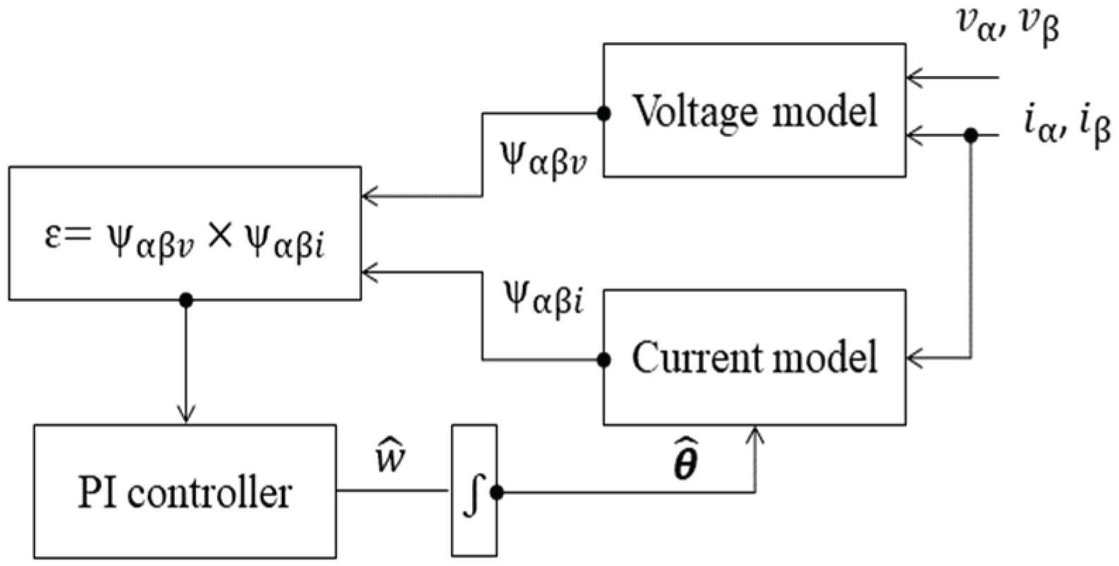
Figure 2.
Simulation of PWM signals and the corresponding d-q-currents in one switching period.
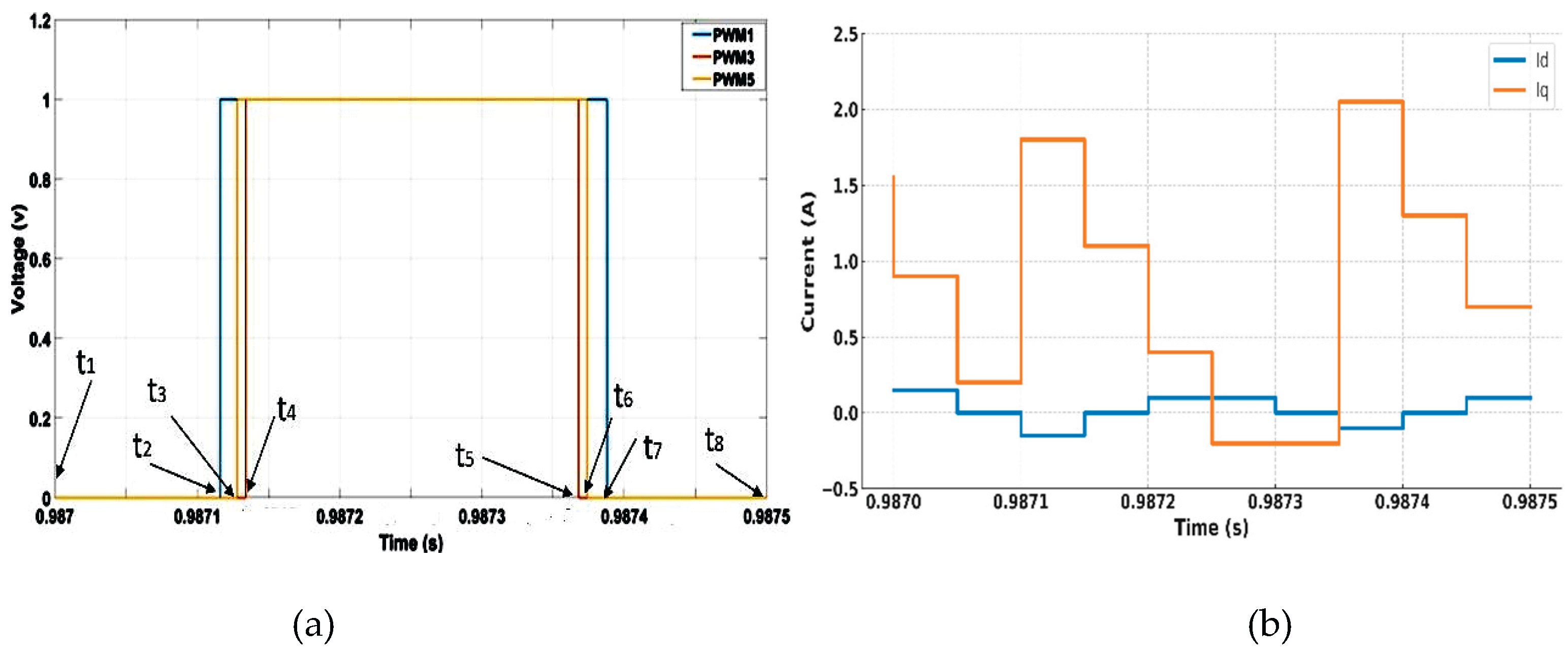
Figure 3.
Simulation result of , when speed changes from 40 to 100 rad/s at 2s under load of 3 Nm.
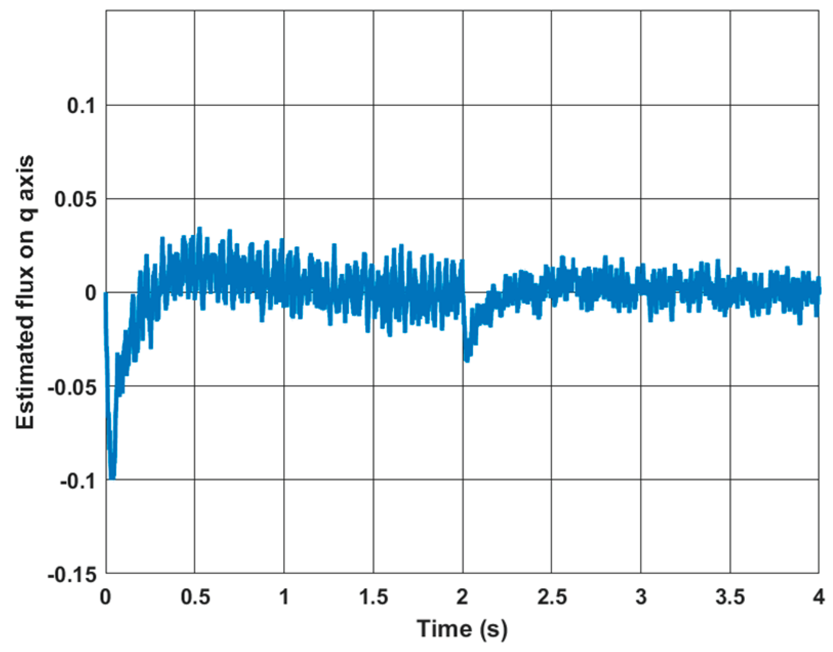
Figure 4.
Block diagram of the novel estimator.
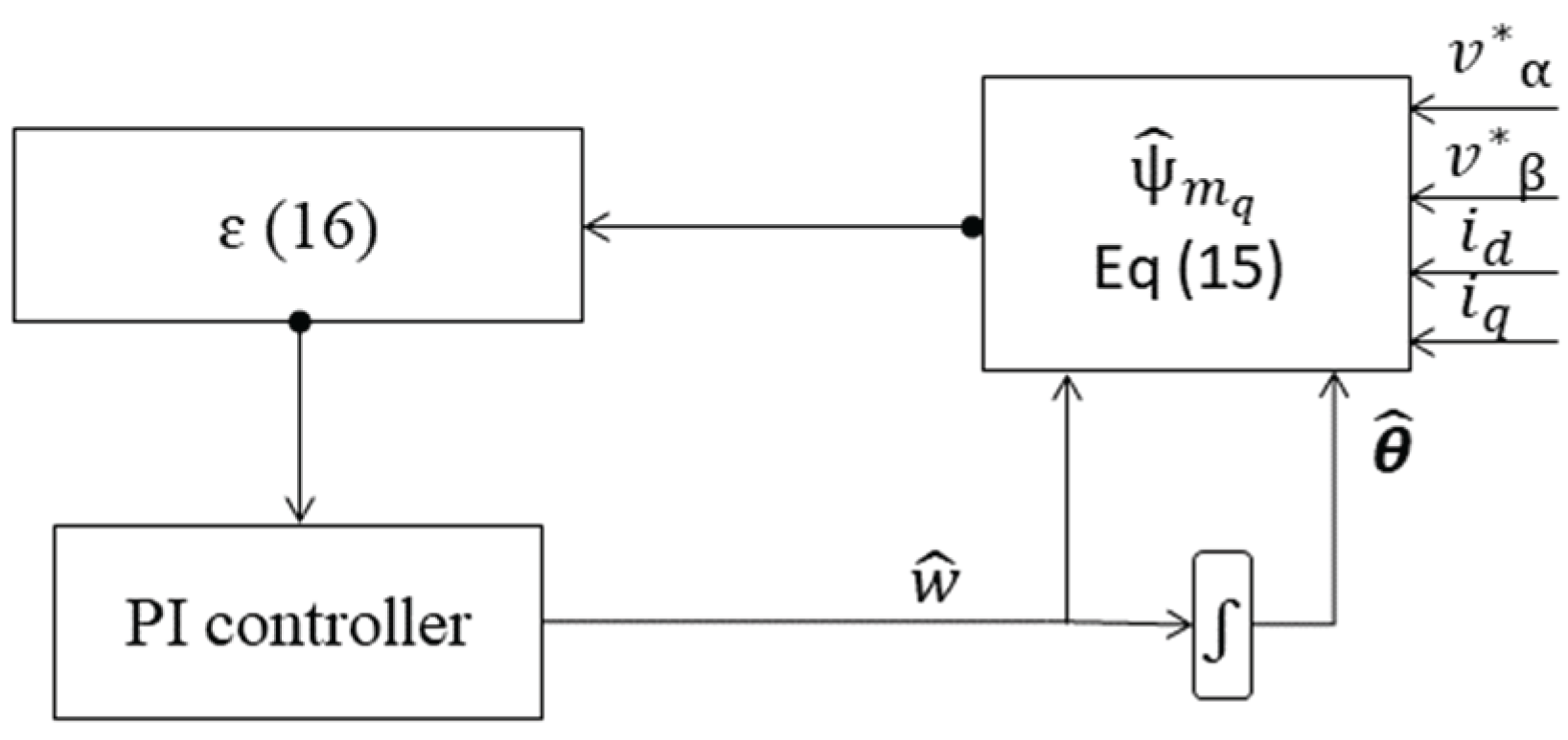
Figure 5.
Experimental test rig.
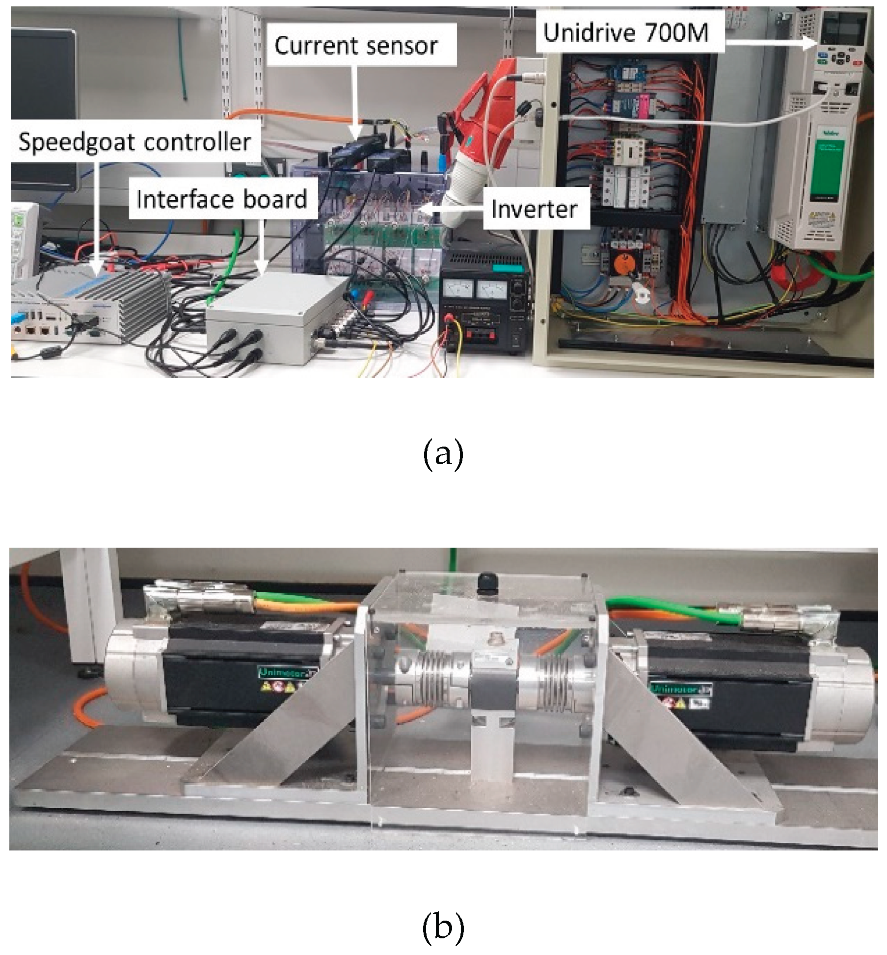
Figure 6.
The block diagram of both sensorless PMSM drives.
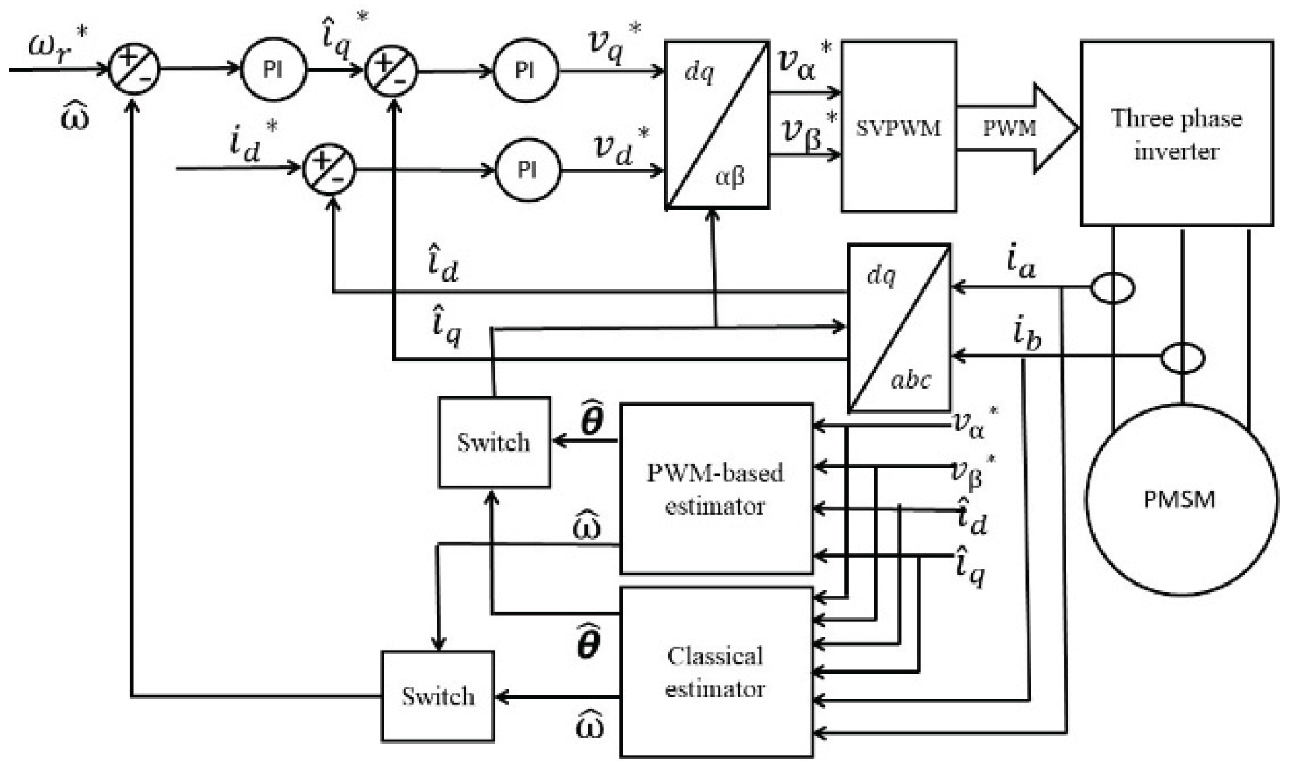
Figure 7.
Injection method combined with the novel method, (a) Speed response, (b) position error, (c) measured and estimated position for the new method, (d) phase currents.
Figure 7.
Injection method combined with the novel method, (a) Speed response, (b) position error, (c) measured and estimated position for the new method, (d) phase currents.
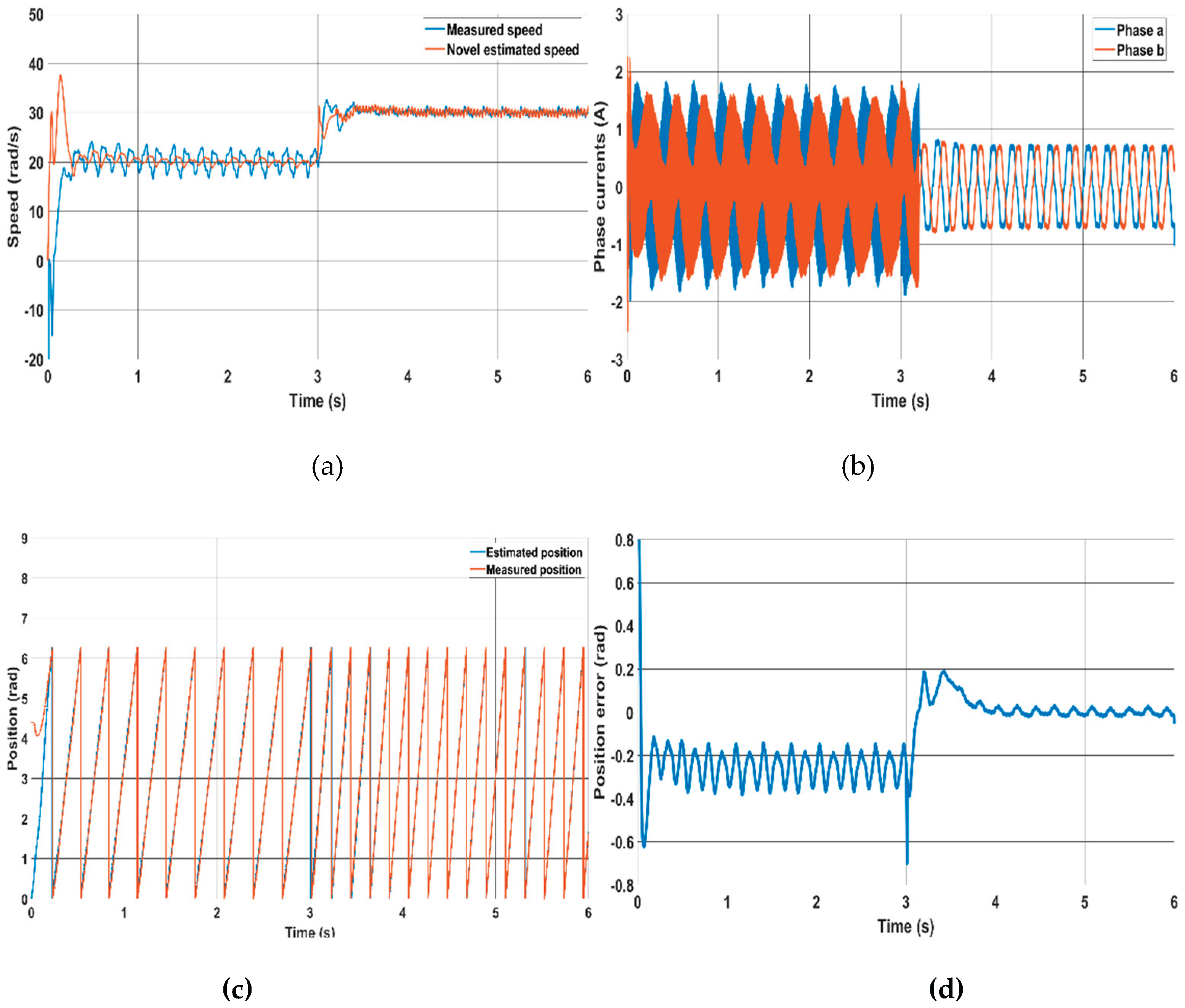
Figure 8.
Novel method performance at low speeds at 30 rad/s, 20 rad/s, 15 rad/s and 10 rad/s, (a) Speed response, (b) position error, (c) Rotor positions, (d) Phase currents, (e) d-q currents.
Figure 8.
Novel method performance at low speeds at 30 rad/s, 20 rad/s, 15 rad/s and 10 rad/s, (a) Speed response, (b) position error, (c) Rotor positions, (d) Phase currents, (e) d-q currents.
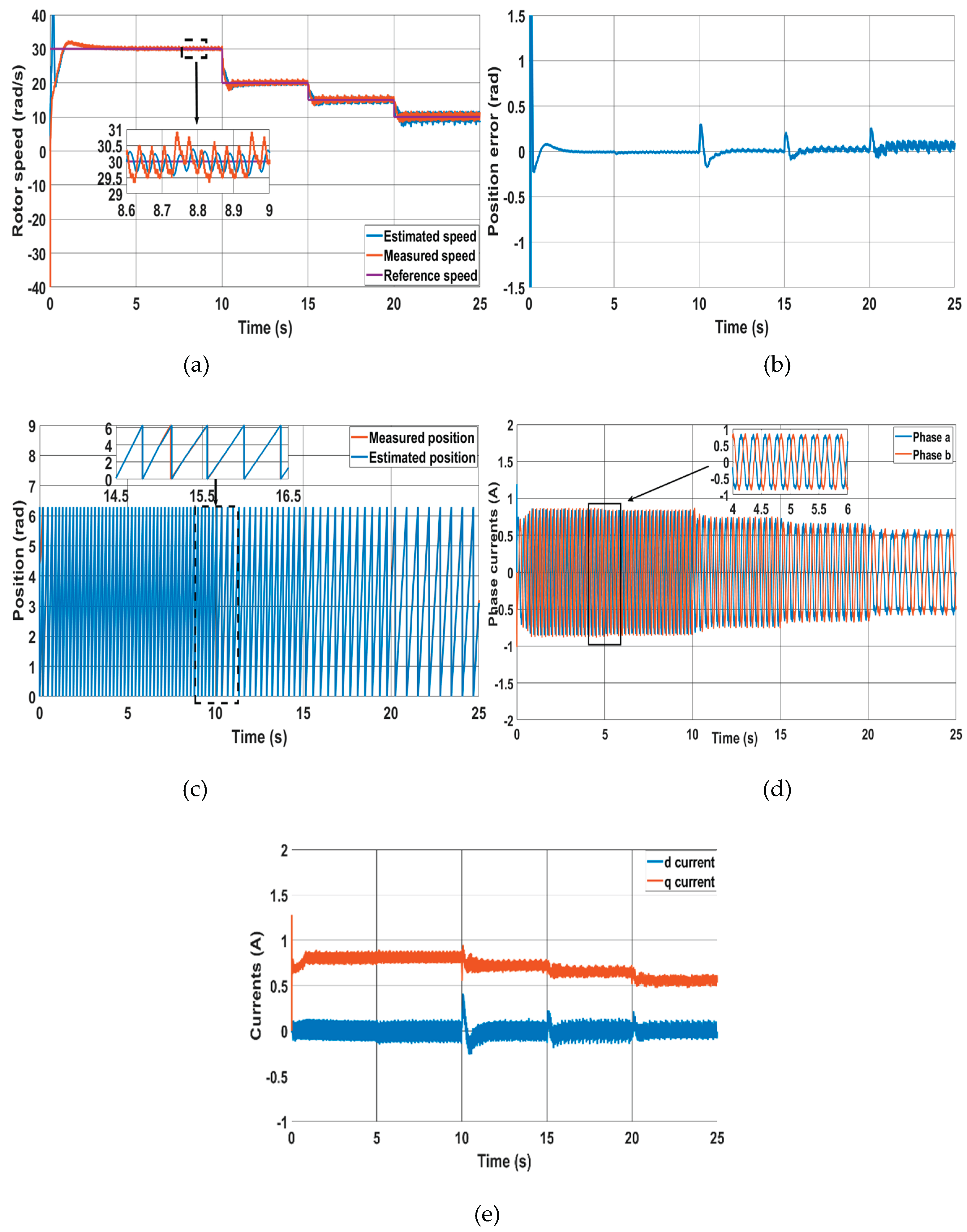
Figure 9.
Classical method at 30 rad/s, 20 rad/s, 15 rad/s and 10 rad/s, (a) Speed response, (b) position error, (c) Estimated and measured positions, (d) Phase currents, (e) d-q currents.
Figure 9.
Classical method at 30 rad/s, 20 rad/s, 15 rad/s and 10 rad/s, (a) Speed response, (b) position error, (c) Estimated and measured positions, (d) Phase currents, (e) d-q currents.
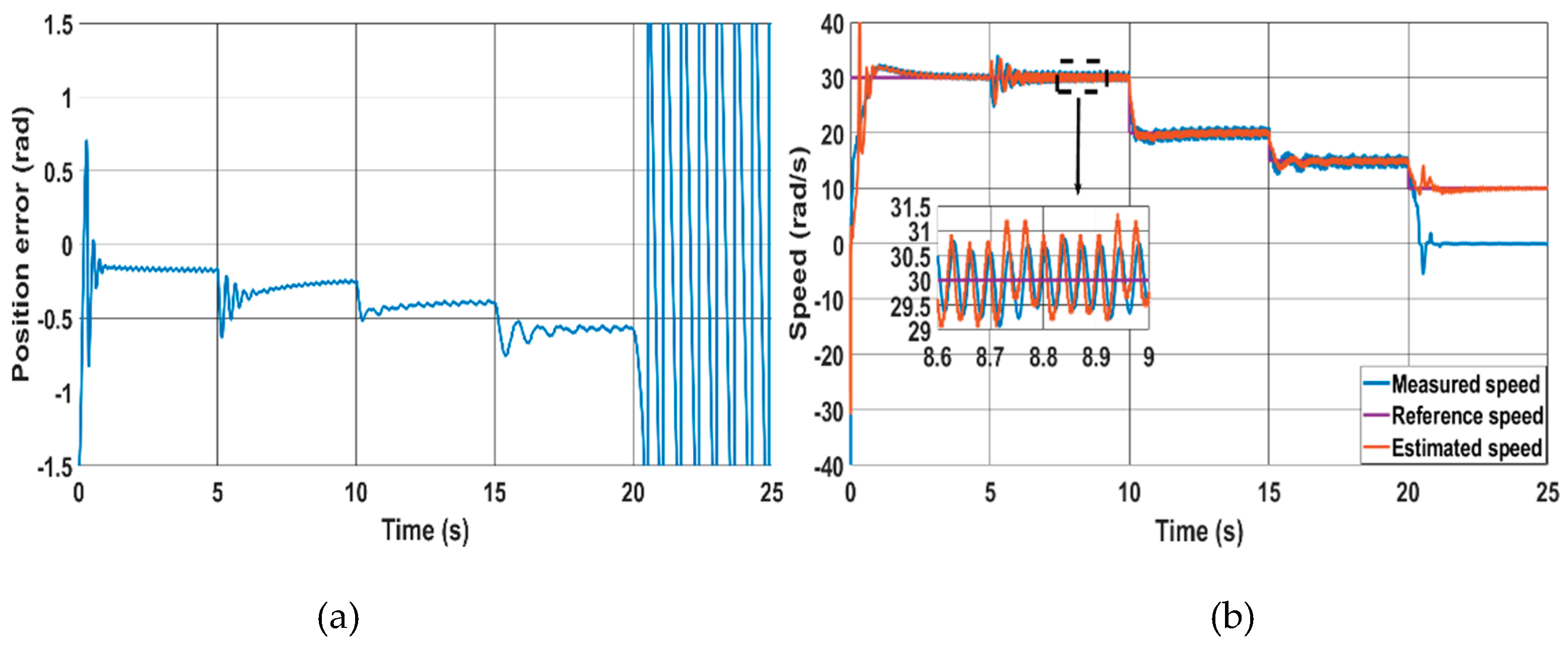
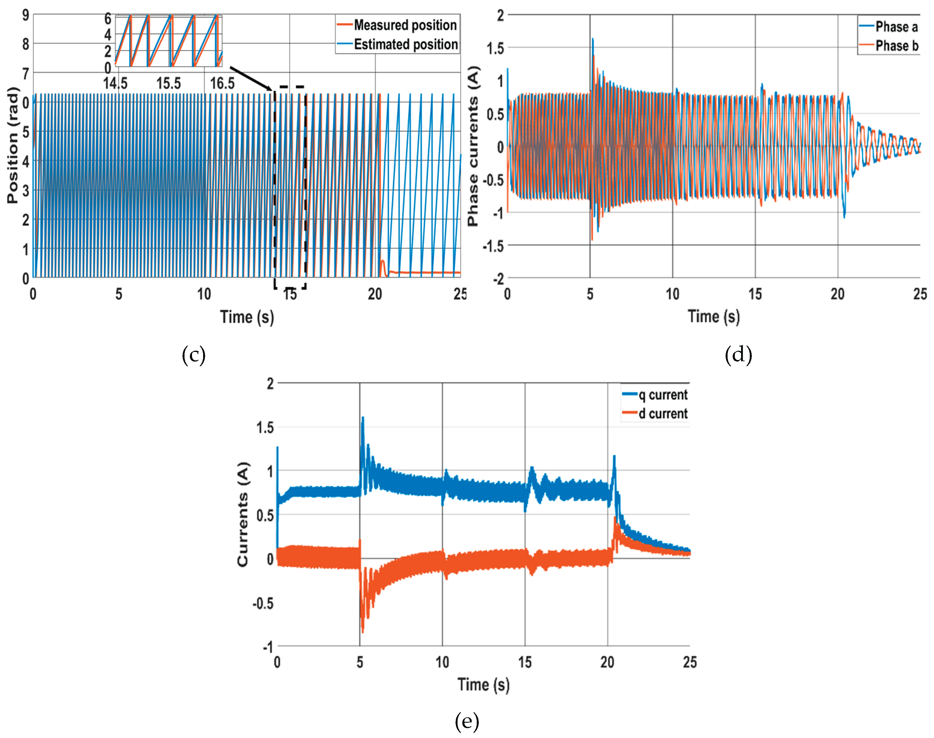
Figure 10.
Motoring mode at 20% and 40% of rated torque, (a) Speed error for the novel, (b) position error for the novel, (c) Speed error for the classical, (d) position error for the classical.
Figure 10.
Motoring mode at 20% and 40% of rated torque, (a) Speed error for the novel, (b) position error for the novel, (c) Speed error for the classical, (d) position error for the classical.
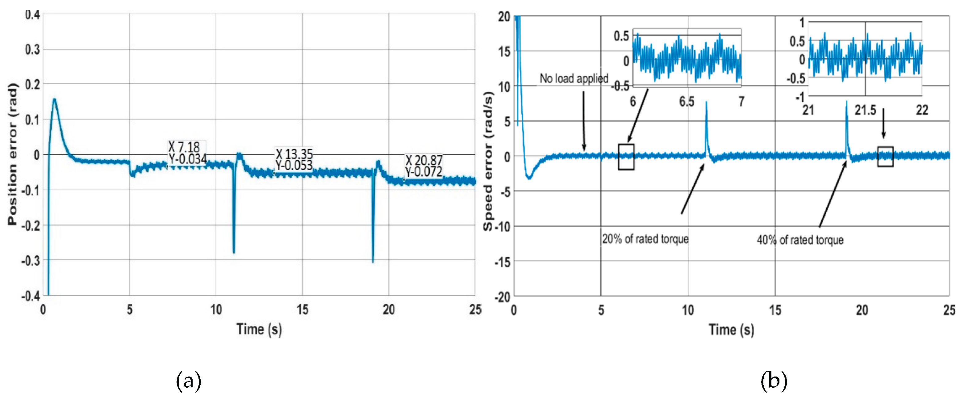
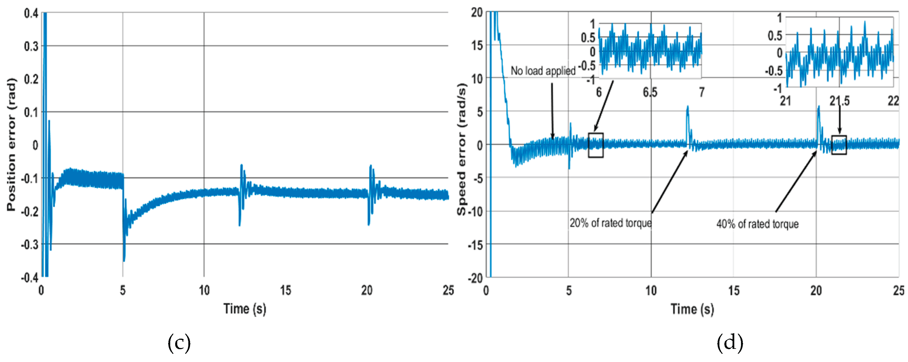
Figure 11.
Sensorless operation with regenerative mode at 20% and 40% of rated torque, (a) Speed error for the novel, (b) Corresponding position error for the novel, (c) Speed error for the classical MRAS, (d) Position error for the classical MRAS.
Figure 11.
Sensorless operation with regenerative mode at 20% and 40% of rated torque, (a) Speed error for the novel, (b) Corresponding position error for the novel, (c) Speed error for the classical MRAS, (d) Position error for the classical MRAS.
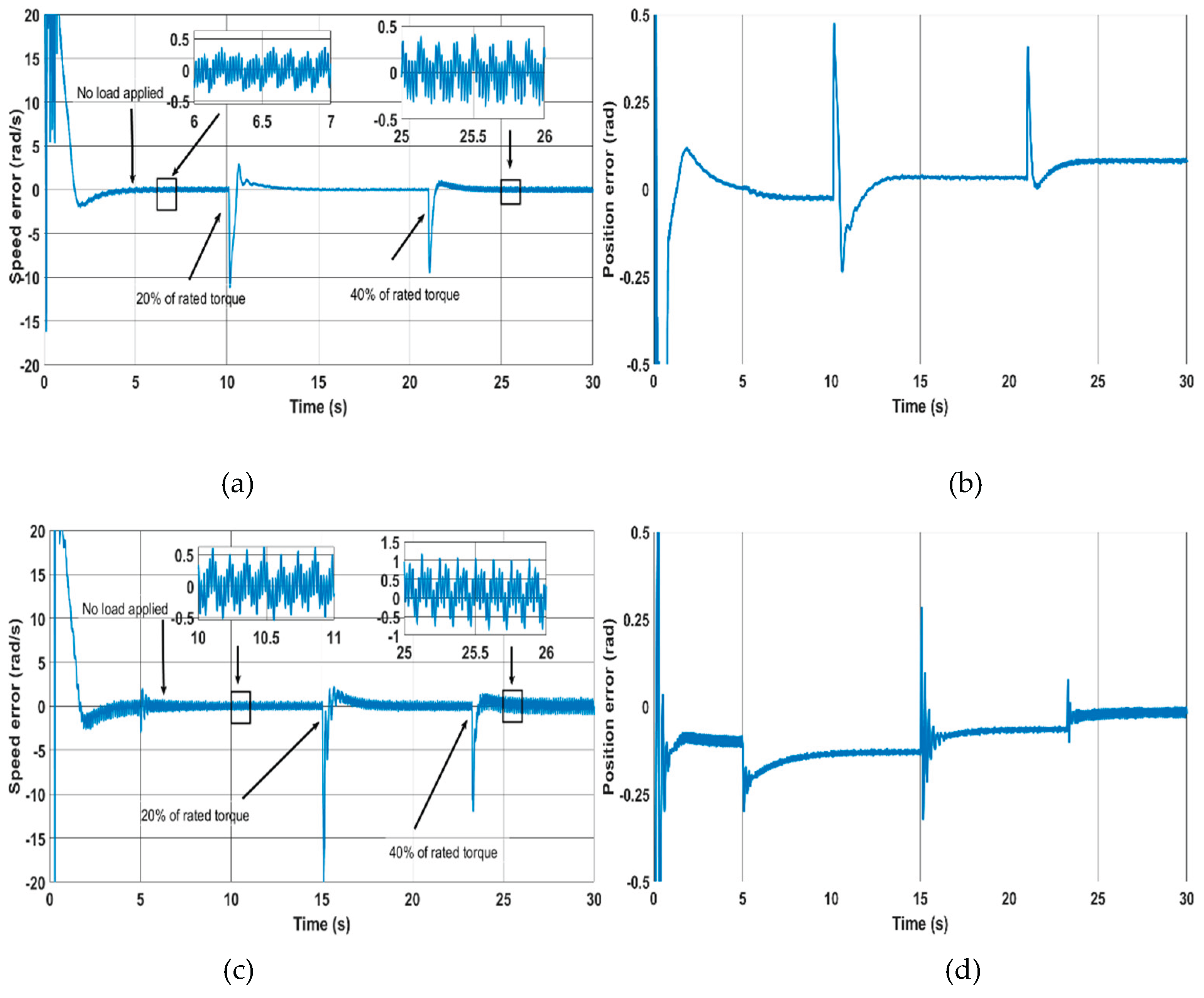
Figure 12.
Performance of the classical MRAS at different switching frequencies (a) speed response (b) position error.
Figure 12.
Performance of the classical MRAS at different switching frequencies (a) speed response (b) position error.
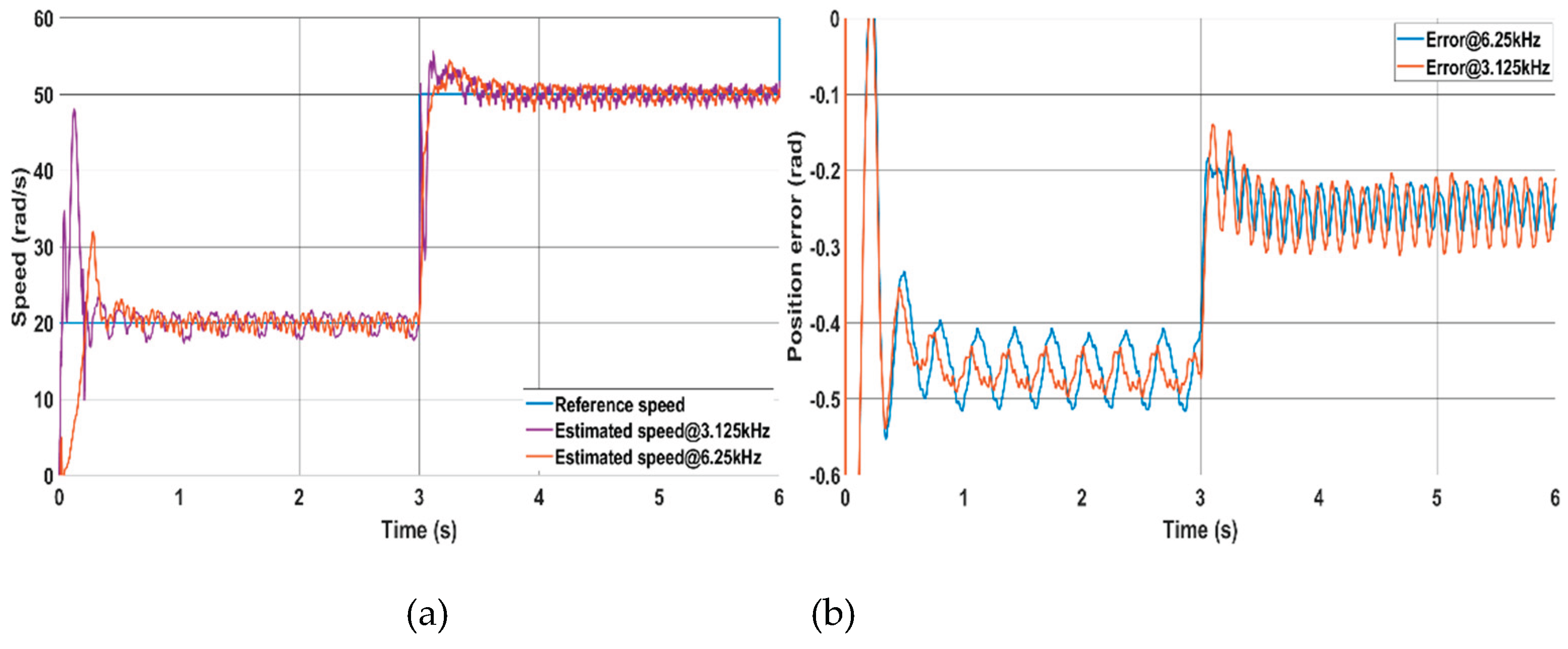
Figure 13.
Effect of stator resistance change on both methods (50% and 100% step changes), (a) speed response, (b) position error.
Figure 13.
Effect of stator resistance change on both methods (50% and 100% step changes), (a) speed response, (b) position error.
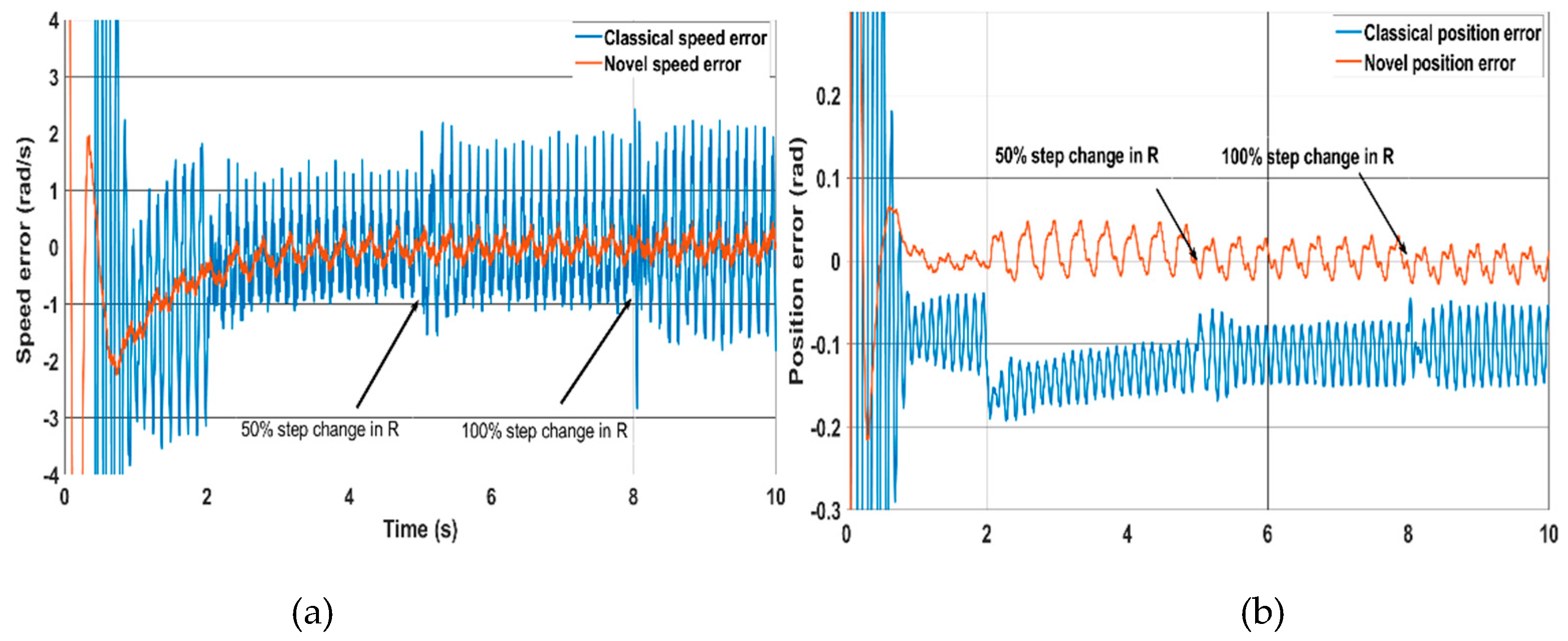
Figure 14.
Effect of q-inductance change on both methods (20% and 40% step changes), (a) speed error, (b) Corresponding position error.
Figure 14.
Effect of q-inductance change on both methods (20% and 40% step changes), (a) speed error, (b) Corresponding position error.
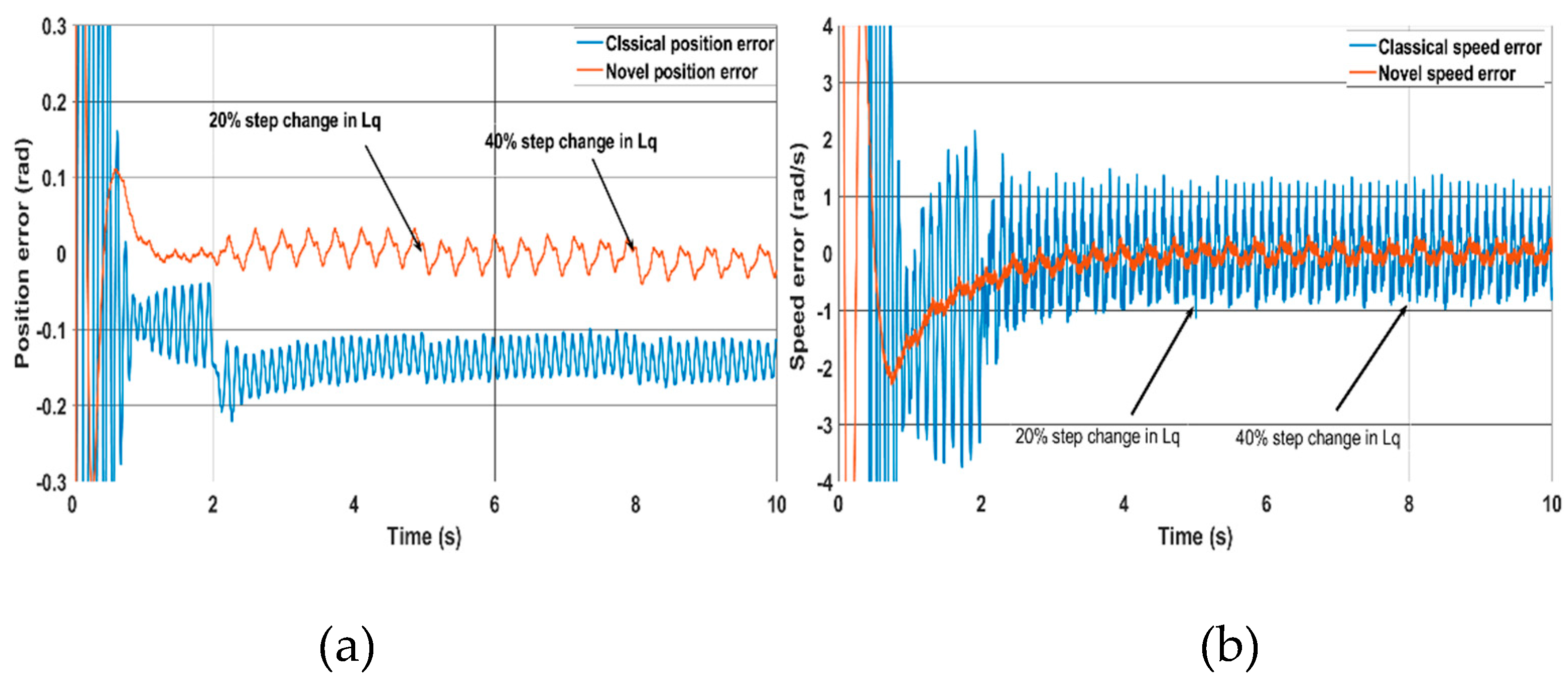
Figure 15.
Effect of nonzero d-Axis currents on the estimated position accuracy for the novel method.
Figure 15.
Effect of nonzero d-Axis currents on the estimated position accuracy for the novel method.
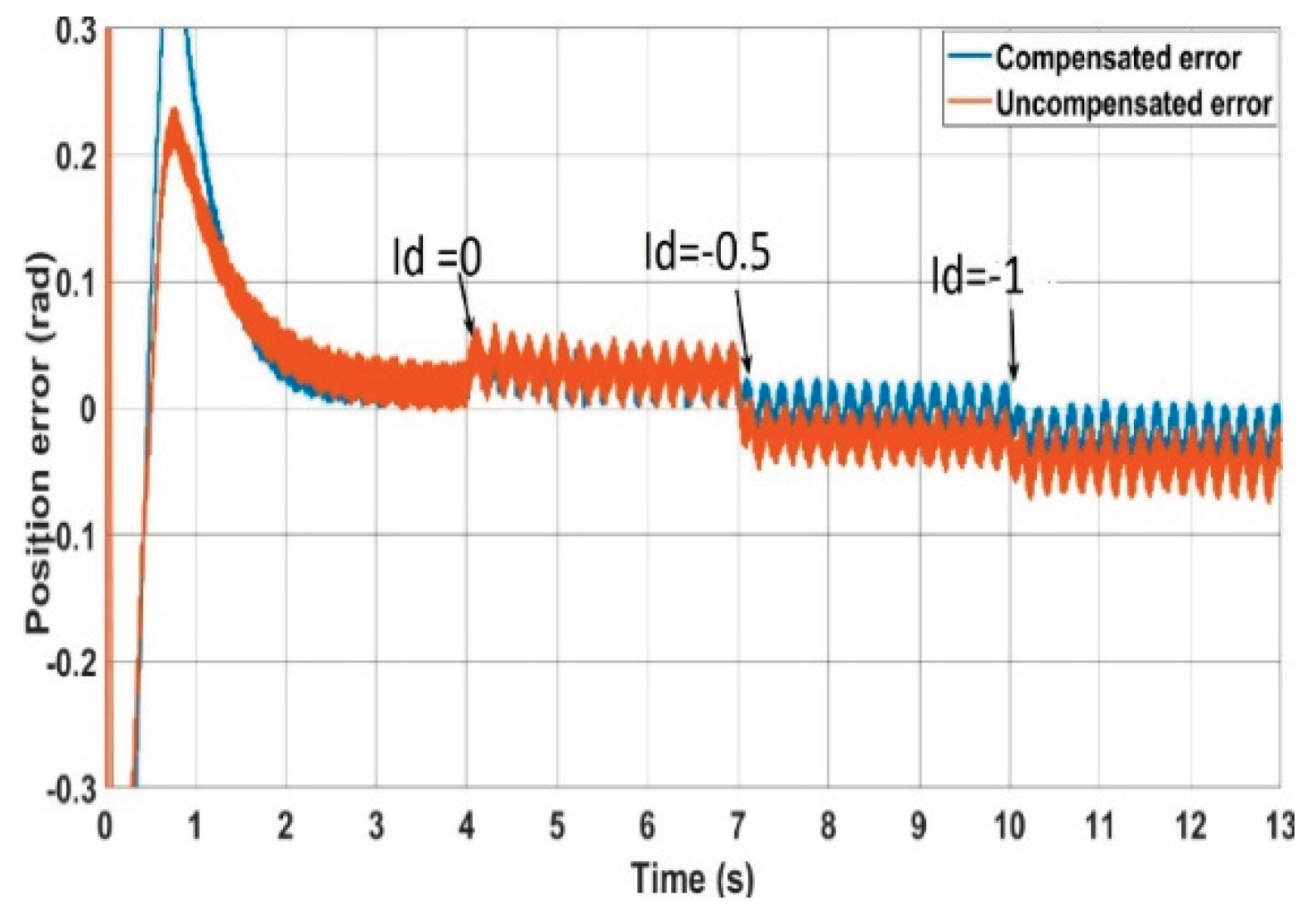

Table 1.
machine parameters.
| Quantity | Unit | Value |
| Pole-pairs | -- | 3 |
| Rated Power | kW | 2.1 |
| Stator resistance | Ω | 2.19 |
| Rated current | A | 4.2 |
| Base speed | rpm | 3000 |
| Rated torque | Nm | 6.7 |
| Torque constant | Nm/A | 1.6 |
| PM flux linkage | V/Hz | 0.356 |
| mH | 12.5 | |
| mH | 15 | |
| Inertia | Kg. | 0.00077 |
Disclaimer/Publisher’s Note: The statements, opinions and data contained in all publications are solely those of the individual author(s) and contributor(s) and not of MDPI and/or the editor(s). MDPI and/or the editor(s) disclaim responsibility for any injury to people or property resulting from any ideas, methods, instructions or products referred to in the content. |
© 2025 by the authors. Licensee MDPI, Basel, Switzerland. This article is an open access article distributed under the terms and conditions of the Creative Commons Attribution (CC BY) license (http://creativecommons.org/licenses/by/4.0/).
Copyright: This open access article is published under a Creative Commons CC BY 4.0 license, which permit the free download, distribution, and reuse, provided that the author and preprint are cited in any reuse.


