
Submitted:
08 August 2025
Posted:
12 August 2025
You are already at the latest version
Abstract
The very high energy electron (VHEE) beams, with energies ranging from 50 to 300 or to 400 MeV, are the subject of intense research investigation, drawing considerable interest in radiotherapy due to their accurate penetration into large and deeply seated tissue, sharp beam edges, high sparing properties, and low sensitivity to tissue density. The Very-High Energy Electron beam ranges from 50 to 400 MeV, and Ultra-High Energy Electron even to 1-2 GeV beams are considered extremely effective for human tumor therapy, while avoiding the spatial requirements and cost of proton and heavy ion facilities. Many research laboratories have developed advanced testing infrastructures with VHEE beams in the USA, Europe, Japan, and other countries. Those facilities aim to accelerate the transition to clinical application, following extensive simulations for beam transport that support preclinical trials and imminent clinical deployment. However, the clinical implementation of VHEE for FLASH radiation therapy requires advances in several areas: developing compact, stable, and efficient accelerators, defining sophisticated treatment planning, and establishing clinically validated protocols. In addition, the perspective of VHEE to access ultra-high dose–rate (UHDR) dosimetry regime presents a promising procedure for the practical integration of FLASH radiotherapy of deep tumors, enhancing normal tissue sparing while maintaining the inherent dosimetric advantages. In this paper, we explore the technological progress and the electron accelerator beam energy technology evolution getting via the ASTRA code simulation results for the VHEE and UHEE beam development provided to medical applications.
Keywords:
VHEE
; electron accelerator technology
; FLASH radiation therapy
; ultra high dose rate
; dosimetry
; ASTRA and FLUKA/FLAIR codes
1. Introduction
It has recently been reported [1,2] a continuous increase, from about 18 million to almost 30 million people, in cancer incidents over the recent years, towards 2040, necessitating the need for an advanced treatment method. A major part of cancer patients are treated with radiation therapy [3], an effective tool for treating cancer. A charged particle beam irradiates with a sufficient dose to eliminate tumor growth and minimize the damage to neighboring normal tissues. Figure 1 [4] shows the charged particle beam energy delivery inside the matter. Many charged particle irradiation therapeutic protocols have been developed, implementing proton/Carbon ion therapy [5,6], Very High Energy Electron-VHEE [7], and the FLASH radiation therapy (FLASH-RT) [8,9]. FLASH radiotherapy represents an innovative approach to radiotherapy, exploiting the radiobiological phenomenon known as the FLASH effect [10], and offers the possibility of delivering an extremely high dose rate (>40 Gy/s) while minimizing adverse effects on healthy tissues and organs at risk. This characteristic leads to the damage of cancer cells while causing minimal damage to healthy tissue. The potential advantages of FLASH-RT in cancer treatment were initially observed in 1966, and the interest in this method and its applications was re-revealed in 2014 in the work by Favaudon, V. et al. [11].
The VHEE beam energy regime development for the FLASH radiation therapy with ultra-high dose–rate (UHDR) dosimetry is reported for the accelerating facilities in the large High Energy Physics (HEP) laboratories in Europe, USA, Japan, etc., where the therapeutic schemes are examined according to the electron energy domain [12]. New scientific collaboration consortia have been launched, during the last ten years, as the CLEAR collaboration (CERN Linear Electron Accelerator for Research) [13] in Switzerland, the PRAE: Platform for Research and Applica6ons with Electrons project [14,15,16] in France, the ASTEC CLARA (Compact Linear Accelerator for Research and Applications) [17] in UK, the SPARC at LNF-INFN [18] in Italy and elsewhere. The purpose of these collaborations is to establish novel linear accelerator structures for electron beams, increasing their energies to some hundred MeV, creating testing facilities with ultra-brilliant electron beams that lead to FEL-intense radiation for scientific and industrial use, or to VHEE for medical applications. Those applications focusing on tumour treatment provide simulation studies of many parameters to determine the dose dependency on beam spot dimension, the beam central axis percentage-depth-dose (PDD), and the source-to-surface distance (SSD), as they have extensively reported [2]. Additional operation condition parameters of the accelerator provide the potential of the radiobiological experimental capabilities, defining the state-of-the-art technological design for future planned VHEE FLASH experiments [19].
There has been new interest in VHEE facilities, with the increase of the electron beam energy in the GeV era, due to the innovative technology of compact high-gradient, high-brightness RF-based and/or laser-plasma wakefield accelerators [20].
The wakefield accelerator technology provides a compact, cost-efficient improvement for the high-energy electron beam production [21], which can provide similar dose distributions to photon beams, connected to more intense and more précised electron beam bunches [22,23].
Another interesting advantage of the laser wakefield accelerators is their role in the delivery of FLASH (ultra-high dose rate) irradiations. Given that the FLASH effect can only be exploited under certain beam parameter conditions [24], the flexibility of the modulation of beam parameters afforded by these types of accelerators makes FLASH-VHEE treatments an exciting prospect. The FLASH-RT effect may be achieved under various beam characteristic conditions vs conventional electron beam irradiation, as summarized in Table 1 [2,11,12,25,26].
It is generally considered, the FLASH-RT effect conditions for a dose > 1 Gy, which is more orders of magnitude greater than the usual conventional electron pulse dose (<1 mGy/pulse) [2,11,12,25,26]. The FLASH-RT regime defines for the irradiation conditions of the beam have the following necessary operational parameters [13,14,27,28]:
- Irradiation time ti < 100 ms;
- Average dose rate > 100 Gy/s;
- In-peak dose rate p > 106 Gy/s;
- Pulse repetition frequency PRF > 100 Hz;
- Dose per pulse > 1 Gy.
2. VHEE Beam Energy Evolution to Treatment
The radiation therapy under new protocols implementation of very short pulses of ultra-high dose rate (FLASH) radiation therapy includes important radiobiological advantages [11] which can be facilitated by recent innovative technological developments available with the new generations of developed accelerators. There is tremendous accelerator technology progress with recent advantages providing compact, low-cost, and best performance facilities with high-gradient cavities, making it possible to enrich the medical applications. Very high-energy electron (VHEE) radiotherapy, in the energy range of 50 to 300 MeV, started around the 2000s, being particularly accurate and minimally affecting the healthy tissues be applicable in many deep anatomical tumour areas [29] has also been confirmed to be less expensive than particle therapy facilities (protons or Carbon ions). The VHEE performs tumour treatment via the electromagnetic scanning of electron beams, with high doses per fraction, thereby improving its effectiveness. The most characteristic feature to be taken advantage of is the FLASH effect conditions, under very high dose beam irradiation of the tissues in an extremely short time, preventing the increase in early and late complications of malignant tumours that affect normal tissues, while there has been the tumour maintains control.
The evolution of the current knowledge on ultra-high-dose rate VHEE radiation therapy is presented in the literature, considering the probable future implementation of VHEE therapy for clinical treatment. The advances of the two novel radiation therapy treatment combination have been put forward meaning the Very High Energy Electron (VHEE) beam under FLASH condition radiation therapies, for a single treatment beam shot, resulting in a substantial change in the field of radiotherapy, resulting to the therapeutic problems elimination for the patients [30].
Many years have passed since the use of electron beams by medical linac for radiation therapy, dating back to the early 1950s. Treatment examples on breast, chest, skin, eyes, salivary glands, or part of other organs, considered as a complementary method to the use of photon radiation therapy [31]. Many new techniques were developed with the electron beam collimation, by adaptation of multi-leaf collimators (MLC), to remove the field shaping cut-outs, usually mounted on electron applicators close to the patient [32]. A very common application of electron beam is the intraoperative technique (IOERT), consisting of the application of a dose during or after operation on the tumour mass with electron beam energies between 4 and 12 MeV [33].
A real technological and radiotherapeutic revolution is in progress, as many of the existing low-energy electron linacs have been modified or new ones have been designed to be used after the discovery of the new potential treatment method known as FLASH radiation therapy [11,34].
The VHEE under ultra-fast time pulse radiation treatment implements extreme high-dose rates orders of magnitude greater than those currently used. It has recently been published the efficiency of the FLASH radiation therapy with electrons for tumour inhibition, without damaging to healthy tissue [35,36]. The major advantage of the FLASH treatment is to spare normal tissues from the observed late complications after radiation therapy at conventional dose rate, providing the efficiency against tumour volumes unchanged. Normal tissue sparing by FLASH has been verified in most of the organs in small animal tests. The underlying biological effect mechanisms must be elaborated; the FLASH treatment effect has also been confirmed in a human tumour supporting further studies and clinical trials after the obtained promising results [9].
There is a general effort for the beam parameters related to the beam pulse length, the mean dose rate, the total dose, and the total irradiation time to be optimized to improve the clinical results, without leaving the adopted standard specifications for the FLASH effect, e.g., >1 Gy and 106 Gy/s, respectively, pulse repetition rate of few tens of Hz, and total irradiation time less than 100 ms. A great effort of research emerged aiming to fulfil the conditions for the FLASH effect with various novel technology options. The development and design of the 4th generation FEL accelerator, as the case of the CompactLight [37,38] and EuPRAXIA PP collaborations [39,40], the laser-driven accelerators, which are considered as the subsequent cost-effective accelerator generation for radiotherapy [41], as well as very high-energy electrons (VHEEs) arriving the electron beam energy of more than 100 MeV [42]. Most of the recent works refer to electrons for the FLASH effect, with a beam energy sufficient to deliver radiation to the proper tissues.
However, due to the innovative achievements in high-gradient accelerator technology during the last decades, VHEE radiation therapy involves the use of electron beams in the energy range 100–350 MeV and even more. The complications research study focused on beam delivery and treatment planning [25] with Monte Carlo simulations using the (TOol for PArticle Simulation) TOPAS/GEANT4 codes are indicating increased tissue penetration result versus with low-energy electrons, as shown in Figure 2a. Reduced lateral beam spread with increased energy compared the lower energy electrons, which is further demonstrated across several electron beam energies in Figure 2b. electrons, being lighter particles, also have the potential for rapid treatment delivery by rastering the beam, by electromagnets, over the tumour area [19].
Studies at the CLEAR user facility (CERN) have shown that VHEE beams have a reduced sensitivity to inhomogeneities compared with other charged particles, such as protons, resulting in reduced dose to healthy tissue in heterogeneous regions such as the lung or prostate in a clinical setting [43]. Currently, deep-seated tumours are usually treated due to the development of high-gradient accelerator technology achievements, where the increasing interest in using very high energy beam being able to penetrate to 20-50 cm depths within the patient body [44]. The dosimetry properties of particle beams at various density region interfaces are essential to plan and deliver optimal radiation therapy to patients. The possible discrepancies in high- and low-density regions in the irradiation volume, i.e. the lung, can significantly alter the delivered dose distribution. Those dose range uncertainties caused by such volume inhomogeneities may affect parts of the tumour, being sometimes significantly under-dosed or over-dosed.
There has recently been a real interest in VHEEs due to the novel technological benefits, which overcome many problems originally foreseen for VHEEs. The major problem was the necessary large size of the linear accelerator (LINAC) needed to obtain such high-energy beams, of 1 GeV or more of the electron beam. Simulation studies have shown that those beam energies are producing dose distributions comparable to that of photon beams. The delivery of electron beams is providing advantages over the photon radiation, due to its more precise manipulation with fewer facility components, and time duration shorter, with more intense electron bunches. It is underlined that the FLASH effect can only be exploited under certain beam parameter conditions, the flexibility of the modulation of the electron beam parameters afforded by these accelerators for FLASH-VHEE treatments, as an exciting prospect [24,34].
The double differential scattering cross sections (DDSC) are inversely proportional to the beam electron energy squared. Therefore, various scattering effects, inside the patient’s body, are relatively reduced by the energy increase. Consequently, the VHEE beam spot is much sharper for lower depths and increases for deep-seated targets. Additionally, simulation results exclusively for the case of the Ultra-High Energy Electron (UHEE) beams [45], up to 1.2 GeV determine the relative biological effectiveness (RBE) by assessing the cell survival of healthy and tumour tissues. It has been reported that the VHEE beam dose is not affected by tumour volume characteristics, as the surface obliquity or depth heterogeneity. The VHEE beam dose, indeed, is maintaining a sustained dose uniformity at organ-tissue interfaces for various densities of tissues: lung, muscle, bone, fat, and air cavities [46]. Subsequently, it has already been reported that this has been confirmed experimentally at CERN [43].
3. Current VHEE Facilities
The major European VHEE facilities currently available, or under development/upgrading, are focusing, aftermath their operation, on the FLASH capabilities for radiobiological applications or clinical treatment, are presented below:
- (i)
- (ii)
- (iii)
- (iv)
In Table 2 is summarized the VHEE facilities’ beam parameters, with the relative energy range (MeV), bunch charge (nC), pulse repetition frequency (Hz) and beam size range providing flexibility in the accelerator design for proper beam delivery.
4. FLASH Electron Beam Injector Simulation Studies
The FLASH effect requirements (see Table 1) define the necessary dose and irradiation time enabling the accelerator system design constraints and proper technical challenges. Similar photocathode and laser system design parameters are also defined.
Simulation results are produced for optimum electron accelerator setup parameters, shown in Table 3, with laser irradiated photocathode obtained via ASTRA code to get FLASH radiation therapy electron beam conditions [2].
The ASTRA code (Space Charge Tracking Algorithm) for the electron beam injector simulation parameters were performed. ASTRA is an open-source software package developed by DESY that permits beam generation and particle tracking through electromagnetic fields [57]. ASTRA is particularly and successfully simulating the space charge-dominated beam effects, applicable likely to our study, resulting to a proper generated beam profile and accelerator lattice with an optimized emittance.
One of the most important accelerator components is the photocathode material playing a definitive parameter role in an RF photoinjector. The well selected photocathode material defines the quantum efficiency (QE) of the electron source and consequently the intrinsic emittance. The semiconductor materials like Caesium Telluride (Cs2Te) are among the most efficient candidate for the photocathode, providing a quantum efficiency (QE) that is much larger in magnitude than metal photocathodes i.e. Copper (Cu) or Magnesium (Mg). Even though, many operators prefer the metal photocathodes due to their huge operational time relative to semiconductors [58]. In Figure 3 the electron accelerator block diagram, is presented, of total length 9.5m, providing an electron beam energy of 128.3 MeV. The accelerator has a Cs2Te photocathode, and an RF gun of 100 MV/m inserting the beam to two S-band accelerating structures, which are housed, each one, inside a strong homogeneous magnetic solenoid. A short-length RF e-gun solenoid just after the photocathode and an injector solenoid with four parts in sequence were selected to optimize the beam emittance. The ASTRA simulation results for the electron beam energy 128.3, 446.1 1 and 1200 MeV are presented in the Figure 4, Figure 5, Figure 6, Figure 7, Figure 8 and Figure 9, with proper important parameters for the optimum injector operation.
In this study there are presented: i) the produced longitudinal electric field Ez (MV/m) in Figure 4; it produces an impressive homogeneity for a proportional electron beam acceleration. ii) the injector solenoid with four sub-parts in sequence per S-band structure provides an homogenous solenoid field Bz (T) shown as a black line and the magnetic field gradient dBr/dr (T/m) shown as a red line vs the beam axis for the first 5 m injector length. The magnetic field was adequately focused on the electron beam after the photocathode along the injector. Additionally, iii) the transverse emittance is presented, where the electron beam is stabilized after the first 75 cm from its production, continuing to the beamline. Iv) the average beam energy is also shown for the first 9.5 m in the injector from the photocathode, with its characteristic proportionality after the 1m distance from the photocathode arriving to a final beam energy of 128.3 MeV. The transverse emittance seems to be constant with low value after some initial oscillations in the first 2 m length of the injector, which is foreseen due to the e-gun beam output.
The final simulation results with the specific characteristics of the e-gun and the injector elements, presented in Figure 4, support the FLASH-RT electron beam specifications, presented in Table 3, which were necessary for the electron dosimetry simulations. In Figure 5, there are presented major output beam distribution plots produced via the ASTRA code, with Cs2Te photocathode, in terms of transverse phase-space vs. z-axis (mm) and z-axis (mm) plus the transverse distribution vs. the x and y axis, respectively, for the beam energy of 128.3 MeV.
The simulation results in Figure 5, show a broader distribution of the transverse phase-space vs the axis x and y, due to the much higher beam energy of 128.3 MeV, instaed of the similar results nearby the e-gun [58] with better beam focusing. The transverse distribution vs. the axis x and y has a well symmetrical beam distributiion.
Similar simulation resulta are presented in Figure 6, Figure 7 and Figure 8 with final beam energy at 446.1 MeV.
The resulted beam parameters shown in the Figure 7 for beam energy 446.1 MeV are quite similar with those results in the Figure 4. There is, also, i) a homogeneity for a proportional electron beam acceleration. ii) the two injector solenoids, having each four parts housing S-band structure produce a homogenous solenoid field Bz (T) shown as a black line and the magnetic field gradient dBr/dr (T/m) shown as a red line vs. the beam axis for the first 10 m injector length. The magnetic field was adequately focused on the electron beam after the photocathode along the injector. Additionally, iii) the transverse emittance is shown, where the electron beam is stabilized after the first 2 m from its production and continues to the beamline. Iv) the average beam energy is also shown for the injector length 27.5 m from the photocathode, with its characteristic proportionality after 1 m from the photocathode arriving at a final beam energy to 446.1 MeV. The transverse emittance seems to be constant with low value after some initial oscillations in the first 2 m length of the injector, which is foreseen due to the e-gun beam output.
In Figure 8 there are presented major output beam distribution plots produced via the ASTRA code, with Cs2Te photocathode, in terms of transverse phase-space vs. z-axis (mm) and z-axis (mm) plus the transverse distribution vs. the x and y axis, respectively, for the beam energy of 446.1 MeV. These beam distribution output results are much broader on transverse phase-space vs. x-axis (mm) and y-axis (mm), due to the much higher energy of 446.1 MeV.
Similar simulation results can been obtained for the beam energy of 1.2 GeV, which confirms the possibility to get a VHEE condition, for FLASH RT, with a relatively much less cost than other electron accelerators with X-band cavities and more expensive RF supply.
5. Beam Dose Distribution Simulation Studies
Simulation studies for the beam dose rate and other parameters have usually been performed through variation of the experimental setup geometry, beam charge current, repetition rate, et.
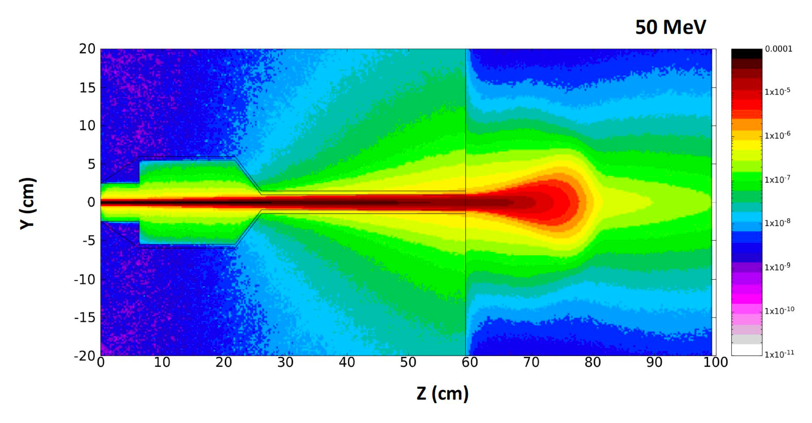
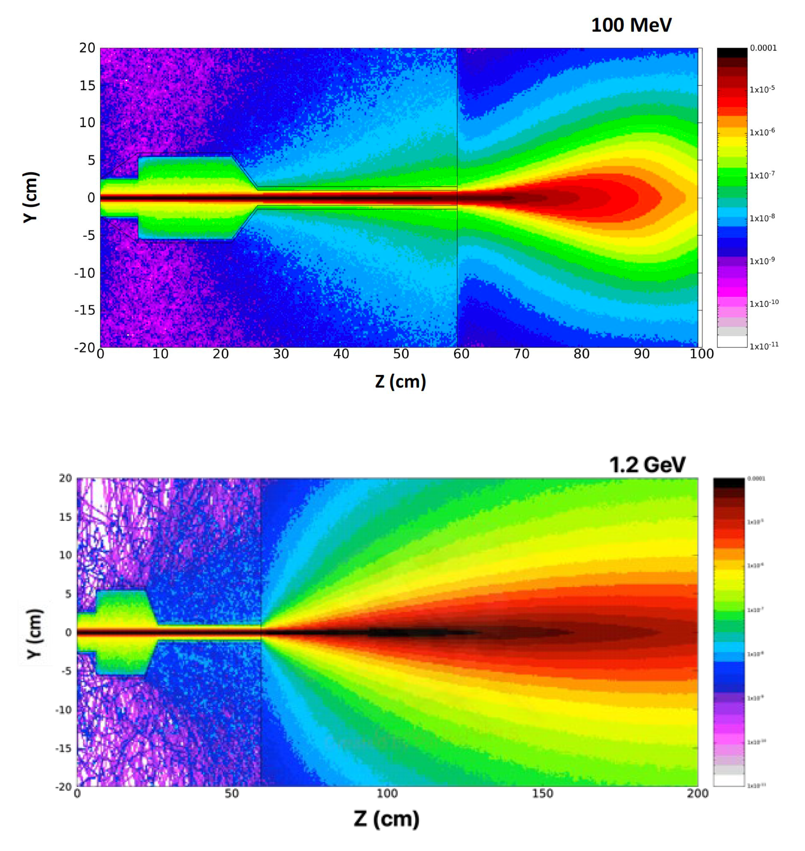
An accurate, user-friendly code is the TOPAS (TOol for PArticle Simulation), based on the GEANT4 particle tracking code, properly implemented for the large LHC experiments. Some characteristic simulaiton results of the 2D beam dose distribution, with the FLUKA code for the electron higher energies of 50, 100 MeV, and 1.2 GeV are presented in Figure 9 [2]
6. Conclusions
The practical range of electrons in matter depends on beam energy and beam width, due to lateral scattering of electrons in matter. Similarly, the VHEE dose profile depends on electron beam energy and beam width. The beam spread and the central-axis dose information from dose distributions perpendicular to the beam, and recorded in water at various depths, have been studied [2,8,10].
Some of the VHEE facilities in Europe with capabilities, under operation or development, to be used for FLASH radiation therapy potential application. Simulations of the beam parameters have been performed to explore the VHEE-FLASH irradiation options for further investigation [12,20].
The availability of VHEE and VHEE-FLASH facilities is emphtically increased in Europe and other well developed countries directing undoubtedly the accelerate research to modern radiotherapy techniques. The major target and interest is related to the FLASH radiation therapy [23,29,30], including a fundamental understanding of the biological mechanisms underpinning FLASH sparing in healthy tissue, in paralle with the accelerator parameters defined standardisation to generate a stable, reliable ultra-high dose rate capable in a FLASH effect conditions. Recently a quantitative simulation study based on the radiolytic oxygen depletion hypothesis reported to investigate the oxygen depletion affect during FLASH irradiation cellular response [35]. In this study the impact of radiolytic oxygen depletion (ROD) is analysed, determining the DNA damage on the cellular response by FLASH radiation therapy.
It is emphasized the accurate and reliable radiation dosimetry allowing for radiobiological study of FLASH mechanisms and healthy and tumour cell effects across the full VHEE clinical energy range, and comparison between facilities submitting a standardised VHEE-FLASH protocol to be established in terms of beam parameters and irradiation procedure [25,43,44,45,46]. This will prove an important step on the way of the VHEE-FLASH protocol to clinical implementation.
There are only a few accelerator systems, at present, that can operate at the ultra-high dose rates associated with the FLASH effect. Although most FLASH studies to date have been performed with experimental very low energies 4–6 MeV electron devices or modified clinical linacs [59]. It is needed to be understood the FLASH irradiation constitutes in terms of the technical beam parameters needed to induce the FLASH beam effect. It is also needed to understand the effects of the manipulation of the technical beam parameters on the magnitude of the FLASH effect. This knowledge may be used to elucidate the biological mechanism during the FLASH effect underlying among the irradiated cells and allow for an optimization during the FLASH radiation therapy in terms of normal tissue sparing to critical organ systems.
In 2021, the CHUV/Lausanne University Hospital team have succeeded using two electron beams of about 9 MeV (Mobetron/IntraOp and FLASH knife/PMB-Alcen) to treat superficial skin cancers and for intraoperative treatment of other types of cancer [60]. A sequential important approach is the established collaboration between CHUV and CERN, the European Council for Nuclear Research in Geneva (https://cerncourier.com/a/adapting-clic-techfor-flash-therapy), aiming to produce a very high energy electron (VHEE)-FLASH device that can deliver high doses at high dose rates to relatively large volumes and deep-seated tumours [61,62,63].
Author Contributions
N.G.; Accelerator design, conceptualization, software and methodology and editing, E.G., validation, formal analysis and investigation on medical application and editing.
Acknowledgments
This work has been supported in part by funded by the European Union’s Horizon 2020 research and innovation programme EuPRAXIA PP, under the Grant Agreement No. 101079773. The contents of this work reflect only the view of the authors. The European Commission is not responsible for any use that may be made of the information it contains. The authors are gratefult to our PhD student, Emmanuil Trachanas for his simulation work on the ASTRA code and to Anna Giribono for her support on the TW C-band structures field map.
Conflicts of Interest
The authors declare no conflicts of interest on this work.
References
- Abdel-Wahab, M.; Gondhowiardjo, S.S.; Rosa, A.A.; Lievens, Y.; El-Haj, N.; Rubio, J.A.P.; Ben Prajogi, G.; Helgadottir, H.; Zubizarreta, E.; Meghzifene, A.; et al. “Global Radiotherapy: Current Status and Future Directions—White Paper”. JCO Glob. Oncol. 2021, 7, 827–842. [CrossRef]
- Gazis, N.; Bignami, A.; Trachanas, E.; Moniaki, M.; Gazis, E.; Bandekas and D.; Vordos, N., “Simulation Dosimetry Studies for FLASH Radio Therapy with Ultra-High-Dose Rate (UHDR) Beam”, Quantum Beam Sci. 2024, 8, 13. [CrossRef]
- Gianfaldoni, S.; Gianfaldoni, R.; Wollina, U.; Lotti, J.; Tchernev, G. and Lotti, T.; “An Overview on Radiotherapy: From Its History to Its Current Applications in Dermatology”. Open Access Mac. Journal of Medical Sciences, 2017, 5(4), p.521. [CrossRef]
- Birindelli; G., “Entropic model for dose calculation in external beam radiotherapy and brachytherapy”, 2011, PhD thesis, U. de Bordeaux. https://tel.archives-ouvertes.fr/tel-03214566.
- Tsujii H. “Overview of Carbon-ion Radiotherapy”, IOP Conf. Series: Journal of Physics: Conf. Series 777 (2017) 012032. [CrossRef]
- Tian, X.; Liu, K.; Hou, Y.; Cheng, J.; and Zhang, J.; (2017). The evolution of proton beam therapy: Current and future status (Review). Molecular and Clinical Oncology, 8(1). [CrossRef]
- Panaino C.M.V.; Piccinini S.; Andreassi M.G.; Bandini G.; Borghini A.; Borgia M.; Di Naro A.; Labate L.U.; Maggiulli E.; Portaluri M.G.A.; and Gizzi L.A.; “Very High-Energy Electron therapy toward clinical implementation”, Cancers 2025, 17, 18. [CrossRef]
- Gagnebin, S.; Twerenbold, D.; Pedroni, E.; Meer, D.; Zenklusen, S.; and Bula, C.; “Experimental determination of the absorbed dose to water in a scanned proton beam using a water calorimeter and an ionization chamber”. NIM B: Beam Interactions with Materials and Atoms, 268(5) 2010, pp.524–528. [CrossRef]
- Bourhis, J.; Sozzi, W.J.; Jorge, P.G.; Gaide, O.; Bailat, C.; Duclos, F.; Patin, D.; Ozsahin, M.; Bochud, F.; Germond, J.F.; et al., “Clinical translation of FLASH radio-therapy: Why and how?” Radiother. Oncol., vol. 139, pp. 11–17, 2019. [CrossRef]
- Pratx, G.; Kapp, D.S.; “A computational model of radiolytic oxygen depletion during FLASH irradiation and its effect on the oxygen enhancement ratio,” Phys. Med. Biol, vol. 64, p. 185005., 2019. [CrossRef]
- Favaudon, V.; Caplier, L.; Monceau, V.; Pouzoulet, F.; Sayarath, M.; Fouillade, C.; Poupon, M.F.; Brito, I.; Hupe, P.; Bourhis, J.; et al, “Ultrahigh dose-rate FLASH irradiation increases the differential response between normal and tumor tissue in mice,” Sci. Transl. Med., vol. 12, no. 6, p. 1671, 2020. [CrossRef]
- Naceur A.; Bienvenue C.; Romano P.; Chilian C.; and Carrier J.-F.; “Extending deterministic transport capabilities for very-high and ultra-high energy electron beams”, Scient. Rep. 14: 2796 (2024). [CrossRef]
- Gamba D.; Corsini R.; Curt S.: Doebert S.; Frabolini W.; Mcmonagle G.; Skowronski P.K.; Tecket F.; Zeeshan S.; Adli E.; Lindstrom C.A.; Ross A.; Wroe L.M.; “The CLEAR user facility at CERN”, NIM A 909 (2018) 480-483. [CrossRef]
- Marchand D.; “A new platform for research and applications with electrons: the PRAE project”, EPJ web of Conferences 138, 01012 (2017), ISHEPP XXIII International Baldin Seminar on High Energy. [CrossRef]
- Delorme R.; Marchand D.; and Vallerand C.; “The PRAE Multidisciplinary Project”, Nucl. Phys News, 29, 2019 (1), 32-35. [CrossRef]
- Han Y.; Faus-Golfe A.; Vallerand C.; Bai B.; Duchesne P.; Prezado Y.; Delorme R.; Poortmans P.; Favaudon V.; Fouillade C.; Pouzoulet F.; Dosanjh M.; “Optics design and beam dynamics simulation for a a VHEE radiobiology beamline at PRAE accelerator”, 10th Int. Part. Acc. Conf. IPAC2019. [CrossRef]
- Angal-Kalinin D.a; Boogert S.; and Jones J.K.; “Potential of the CLARA test facility for VHEE rationteraly research”, Front. Phys. 12 (2024):1496850. [CrossRef]
- Ferrario M.; Alesini D.; Anania M.; Bacci A.; Bellaveglia M.; Bogdanov O.; Boni R.; Castellano M.; Chiadroni E.; Cianchi A.; et al., “SPARC_LAB present and future”, NIM B: 309 (2013) 183-188. [CrossRef]
- Small K.L.; Angal-Kalinin D.; Jones J.K.; and Jones R.J.; “VHEE facilities I Europe with the potential for FLASH dose irradiation; Conspectus and dose rate parameterisation”, NIM B 565 (2025) 165752. [CrossRef]
- Masilela T.A.M.; Delorme R.; and Prezado Y.; “Dosimetry and radioprotection evaluations of very-high energy electron beams”, Scient. Rep. 11: 20184 (2021). [CrossRef]
- Nakajima, K.; Yuan, J.; Chen, L.; and Sheng, Z.; “Laser-driven very high energy electron/photon beam radiation therapy in conjunction with a robotic system”, Appl. Sci. 5, 1–20, (2015). [CrossRef]
- DesRosiers, C.; Moskvin, V.; Cao, M.; Joshi, C. J.; and Langer, M.; “Laser-plasma generated very high energy electrons in radiation therapy of the prostate”, Proc. SPIE 6881, 49–62, (2008). [CrossRef]
- Kokurewicz, K.; Welsh G.H.; Wiggins S.M.; Boyd M.; Sorensen A.; et al., “Laser-plasma generated very high energy electrons (VHEEs) in radiotherapy”, Proc. SPIE 10239, (2017) 61–69. [CrossRef]
- Poppinga, D.; Kranzer R.; Farabolini W.; Gilardi A.; Corsini R.; Wyrwoll V.; Looe H.K.; Delfs B.; Gabrisch L.; and Poppe L.; “VHEE beam dosimetry at CERN linear electron accelerator for research under ultra-high dose rate conditions”, Biomed. Phys. Eng. Express 7, 015012 (2020). [CrossRef]
- Kokurewicz, K.; Brunetti, E.; Welsh, G.H.; Wiggins, S.M.; Boyd, M.; Sorensen, A.; Chalmers, A.J.; Schettino, G.; Subiel, A.; DesRosiers, C.; et al. “Focused very high-energy electron beams as a novel radiotherapy modality for producing high-dose volumetric elements”,. Sci. Rep. 2019, 9, 10837. [CrossRef]
- Kaiser, A.; Eley, J.G.; Onyeuku, N.E.; Rice, S.R.; Wright, C.C.; McGovern, N.E.; Sank, M.; Zhu, M.; Vujaskovic, Z.; Simone, C.B.; et al. “Proton Therapy Delivery and Its Clinical Application in Select Solid Tumor Malignancies”, J. Vis. Exp. 2019, 144, e58372. [CrossRef]
- Giuliano, L.; Franciosini, G.; Palumbo, L.; Aggar, L.; Dutreix, M.; Faillace, L.; Favaudon, V.; Felici, G.; Galante, F.; Mostacci, A.; et al. «Characterization of Ultra-High-Dose Rate Electron Beams with Electron FLASH Linac”, Appl. Sci. 2023, 13, 631. [CrossRef]
- Montay-Gruel, P.; Petersson, K.; Jaccard, M.; Boivin, G.; Germond, J.-F.; Petit, B.; Doenlen, R.; Favaudon, V.; Bochud, F.; Bailat, C.; et al., “Irradiation in a flash: Unique sparing of memory in mice after whole brain irradiation with dose rates above 100 Gy/s”, Radiother. Oncol. 2017, 124, 365–369. [CrossRef]
- Desrosiers, C.; Moskvin, V.; Bielajew, A.F.; Papiez, L.; “150–250 MeV electron beams in radiation therapy”, Phys. Med. Biol. 2000, 45, 1781–1805. [CrossRef]
- Rongo M.G.; Cavallone M.; Patriarca A.; Leite A.M.; Loap P.; Favaudon V.; Crehange G.; and De Marzi L., “Back to the Future: Very High-Energy Electrons (VHEEs) and their potential applications in Radiation Therapy”, Cancers 2021, 13, 4942. [CrossRef]
- Hogstrom, K.R.; Almond, P.R.; “Review of electron beam therapy physics”, Phys. Med. Biol. 2006, 51, R455–R489. [CrossRef]
- Mueller, S.; Fix, M.K.; Henzen, D.; Frei, D.; Frauchiger, D.; Loessl, K.; Stampanoni, M.F.M.; Manser, P.; “Electron beam collimation with a photon MLC for standard electron treatments”, Phys. Med. Biol. 2017, 63, 025017. [CrossRef]
- Krempien, R.; Roeder, F.; “Intraoperative radiation therapy (IORT) in pancreatic cancer”. Radiat. Oncol. 2017, 12, 8. [CrossRef]
- Vozenin, M.-C.; De Fornel, P.; Petersson, K.; Favaudon, V.; Jaccard, M.; Germond, J.-F.; Petit, B.; Burki, M.; Ferrand, G.; Patin, D.; et al. “The Advantage of FLASH Radiotherapy Confirmed in Mini-pig and Cat-cancer Patients”, Clin. Cancer Res. 2018, 25,35–42. [CrossRef]
- Vozenin, M.-C.; Hendry, J.; Limoli, C. “Biological Benefits of Ultra-high Dose Rate FLASH Radiotherapy: Sleeping Beauty Awoken”, Clin. Oncol. 2019, 31, 407–415. [CrossRef]
- Wilson, J.D.; Hammond, E.M.; Higgins, G.S.; Petersson, K.; “Ultra-High Dose Rate (FLASH) Radiotherapy: Silver Bullet or Fool’s Gold?”, Front. Oncol. 2020, 17, 1563. [CrossRef]
- Gazis N.; Bignami A.; Trachanas E.; Alexopoulos T.; Telali I.; Apostolopoulos T.; Pramatari K.; Karagiannaki K.; Kotsopoulos D; and Gazis E.; “The Innovative FEL design by the CompactLight collaboration”. J. Phys: Conf. Series 2375 (2022) 012006. [CrossRef]
- Gazis N.; Tanke E.; Apostolopoulos T.; “Pramatari K.; Rochow R.; and Gazis E.; Light source in Europe-Case Study: The CompactLight collaboration”. Instruments 3(3) 2019, 43. [CrossRef]
- https://www.eupraxia-pp.org/.
- Giribono A., Alesini D., Bacci A., Bellaveglia M., Cardelli F., Chiadroni E., Del Dotto A., Faillace L., Ferrario M., A Gallo M., et al., “Electron beam analysis and sensitivity studies for the EuPRAXIA@SPARC LAB RF injector”, JoPhys. Conf. Series 2687 (2024) 032022. [CrossRef]
- Bayart, E.; Flacco, A.; Delmas, O.; Pommarel, L.; Levy, D.; Cavallone, M.; Megnin-Chanet, F.; Deutsch, E.; and Malka, V.; “Fast dose fractionation using ultra-short laser accelerated proton pulses can increase cancer cell mortality, which relies on functional PARP1 protein”. Sci. Rep. 2019, 9, 10132. [CrossRef]
- Zhu H.; Li J.; Deng X.; Qiu R.; Wu Z.; and Zhang H.; “Modeling of cellular responses after FLASH irradiation: a quantitative analysis based on the radiolytic oxygen depletion hypothesis”. 2021. arXiv:2105.13138 [physics.med-ph]. [CrossRef]
- Bazalova-Carter, M.; Qu B.; Palma B.; Hardemark B.; Hynning E.; Jensen C.; and Maxim P.;, “Treatment planning for radiotherapy with very high-energy electron beams and comparison of VHEE and VMAT plans”, Med. Phys. 42 (2015) 2615–2625. [CrossRef]
- Lagzda Aangal-Kalinin D.; Jones J.; Aitkenhead A.; Kirkby K.J.; MacKay R.; Van Herk M.; Farabolini W.; Zeeshan S.; Jones R.M.;, “Influence of heterogeneous media on Very High Energy Electron (VHEE) penetration and a Monte Carlo-based comparison with existing radiotherapy modalities”. Nuclear Inst. and Methods in Physics Research, B. 482 (2020) 70–81. [CrossRef]
- Grunwald K.; Desch K.; Elsner D.; Proft D. and Thome L.; “Dose simulation of Ultra-High Energy Electron beam for novel FLASH radiaiton therapy applications”, JoPhys. Conference Series, IPAC 2023, 4993-4995. [CrossRef]
- DesRosiers, C.M.; “An evaluation of very high energy electron beams (up to 250 MeV) in radiation therapy”. PhD dissertation, Purdue University (2004). https://docs.lib.purdue.edu/dissertations/AAI3166611/.
- Maxim P.G.; Tantawi S.G.; Loo B.W.; “PHASER: A platform for clinical translation of FLASH cancer radiotherapy”. Radiother. Oncol. 139 (2019) 28–33. [CrossRef]
- Korysko P.; Dosanjh M.; Dyks L.A.; Bateman J.J.; Robertson C.; Corsini R.; Farabolini W.; Gilardi A.; Sjobak K.N.; and Ricker V.; “Updates, status and experiments of CLEAR, the CERN Linear Electron Accelerator for Research”. Proc. 13th Int. Particle Accelerator Conf. (2022). [CrossRef]
- Burkart F.; Assmann R.W.; Dinter H.; Jaster-Merz S.; Kuropka W.; Mayer F.; Stacey B.; and Vinatier T.; “The ARES linac at DESY”. Proc. 31st Int. Linear Accel. Conf. (2022). [CrossRef]
- Vinatier T.; Assmann R.W.; Burkart F.; Dinter H.; Jaster-Merz S.; Kellermeier M.; Kuropka W.; Mayer F.; and Stacey B.; “Characterization of relativistic electron bunch duration and travelling wave structure phase velocity based on momentum spectra”. Phys. Rev. Accel. Beams (2023). [CrossRef]
- Clarke J.A.; Angal-Kalinin D.; Bliss N.; Buckley R.; Buckley S.; Cash R.; Corlett P.; Cowie L.; Cox G.; Diakun G.P.; et al., “CLARA Conceptual Design Report”. Science and Technology Facilities Council, 2013. https://www.astec.stfc.ac.uk/Pages/CLARA_CDRv2.pdf.
- Angal-Kalinin D.; Bainbridge A,; Brynes A.D.; Buckley R.; Buckley S.; Burt G.C.; Cash R.; Castaneda H.M.; and Christie D.; “Design, specifications, and first beam measurements of the compact linear accelerator for research and applications front end”. Phys. Rev. Accel. Beams 23 (2020). [CrossRef]
- Angal-Kalinin D.; Bainbridge A.; Jones J.K.; Pacey T.H.; Saveliev Y.M.; and Snedden E.W.; “The design of the Full Energy Beam Exploitation (FEBE) beamline on CLARA”, Proc. 31st Int. Linear Accel. Conf. (2022). [CrossRef]
- E.W. Snedden, et al., Specification and design for full energy beam exploitation of the compact linear accelerator for research applications, Phys. Rev. Accel. Beams 27 (2024).
- Palumbo L.; Bosco F.; Carillo M.; Chiadroni E.; De Arcangelis D.; De Gregorio A.; Ficcadeni I.; Francescone D.; Franciosini G.; Guliano L.; et al, SAFEST: A compact C-band linear accelerator for VHEE-FLASH radiotherapy, Proc. 14th Int. Particle Accelerator Conf. (2023). [CrossRef]
- Guiliano L.; Carillo M.; Chiadroni E.; De Arcangelis D.; De Gregorio A.; Ficcadeni I.; Francescone D.; Franciosini G.; Magi M.; Migliorati M.; et al., SAFEST project, a compact C-band RF linac for VHEE FLASH radiotherapy, Proc. 15th Int. Particle Accelerator Conf. (2023). [CrossRef]
- Floettmann, K. ASTRA, A Space Charge Tracking Algorithm, Version 3.2; DESY: Hamburg, Germany, 2017.
- Gazis N.; Tanke E.; Trachanas E.; Apostolopoulos T.; Karagiannaki A.; Pramatari K.; Telali I.; Tzanetou K.; Gazis E.; “Photocathode study of the CompactLight Collaboration for a novel XFEL development”, Int. J. Mod Phys. Conf. Series, 50 (2020) 2060007. [CrossRef]
- Schuler, E.; Acharya, M.; Montay-Gruel, P.: Loo Jr., B.; Vozenin, M-C. and Maxim, G. P.; “Ultra-high dose rate electron beams and the FLASH effect: From preclinical evidence to a new radiotherapy paradigm”, Med. Phys. 4993) 2022: 2082-2095. [CrossRef]
- Wu YF, No HJ, Breitkreutz DY, et al. “Technological basis for clinical trials in FLASH radiation therapy: a review”, Appl Rad Oncol. 2021;10(2):6-14. (ISSN: 2334-5446). https://cdn.agilitycms.com/applied-radiation-oncology/PDFs/issues/ARO_06-21_all.pdf.
- Bazalova-Carter M, Qu B, Palma B, et al. «Treatment planning for radiotherapy with very high-energy electron beams and comparison of VHEE and VMAT plans”. Med Phys. 2015;42(5):2615-2625. [CrossRef]
- Schüler E,, Eriksson K., Hynning E, et al.Very high-energy electron (VHEE) beams in radiation therapy; treatment plan comparison between VHEE, VMAT, and PPBS. Med Phys. 2017;44(6):2544-2555. [CrossRef]
- Palma B., Bazalova-Carter M, Hårdemark B, Hynning E., Qu B., Loo B.W. and Maxim P.G.; “Assessment of the quality of very high- energy electron radiotherapy planning”. Radiother Oncol. 2016;119(1):154-158. [CrossRef]
| 1 | The simulated electron beam energies 128.3 and 446.1 MeV are not extracted, as they were exactly foreseen 120 and 450 MeV, due to the S-band cavities length. |
Figure 1.
The charged particle beams: electrons, protons, and Carbon ions, compared to the photon beam irradiation energy distribution versus the material depth [4].
Figure 1.
The charged particle beams: electrons, protons, and Carbon ions, compared to the photon beam irradiation energy distribution versus the material depth [4].
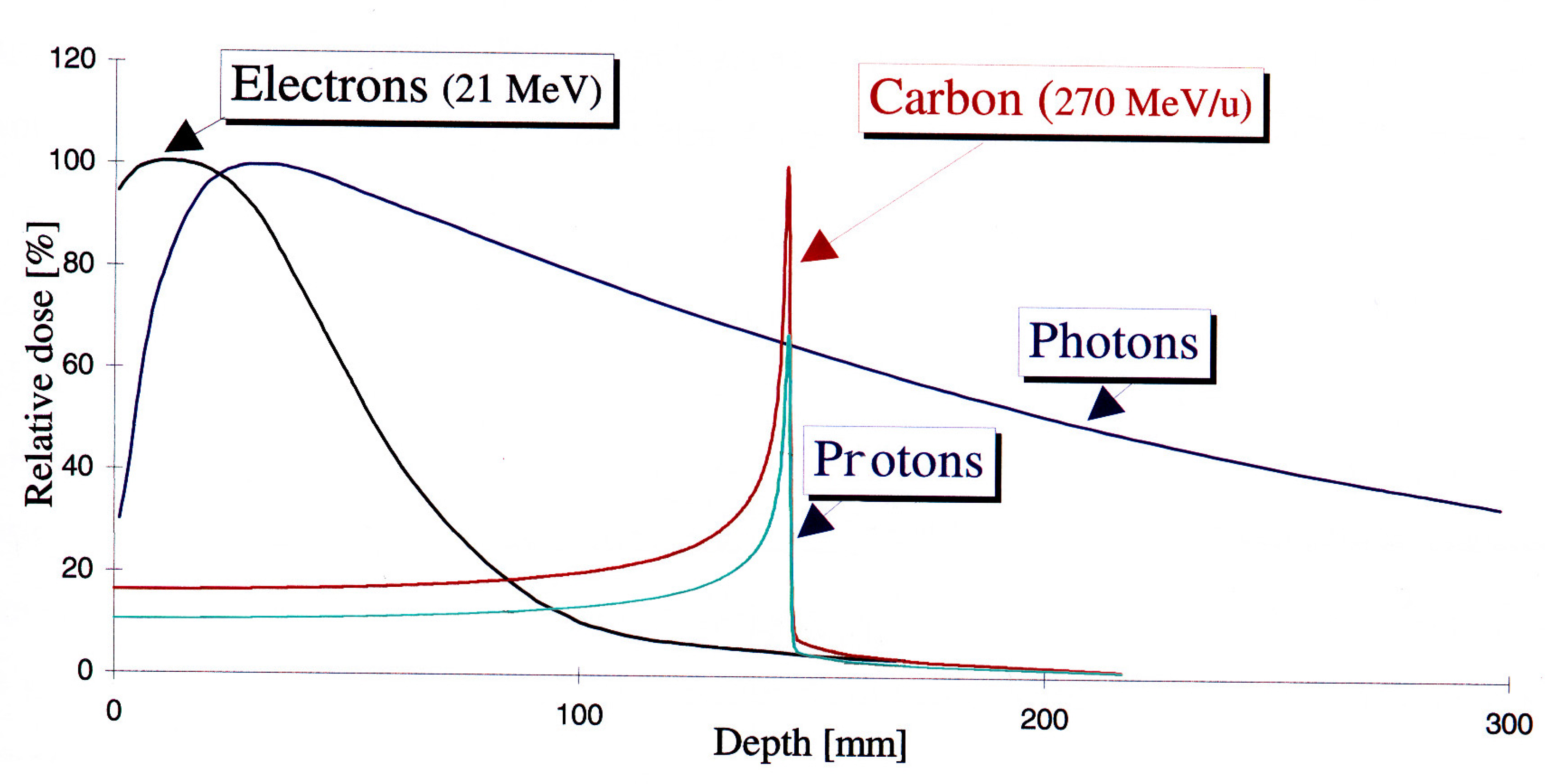
Figure 2.
a) On-axis percentage depth dose (PDD) simulation curves TOPAS/GEANT4 for radiotherapy modalities. Gaussian beam with standard deviation σ = 2 mm incident on a 30x30x30 cm3 water phantom, 301x301x301 bins with 106, 107, and 108 histories for protons, electrons, and photons, respectively. b) Lateral spread of Gaussian electron beam simulations, data with 107 particles [19].
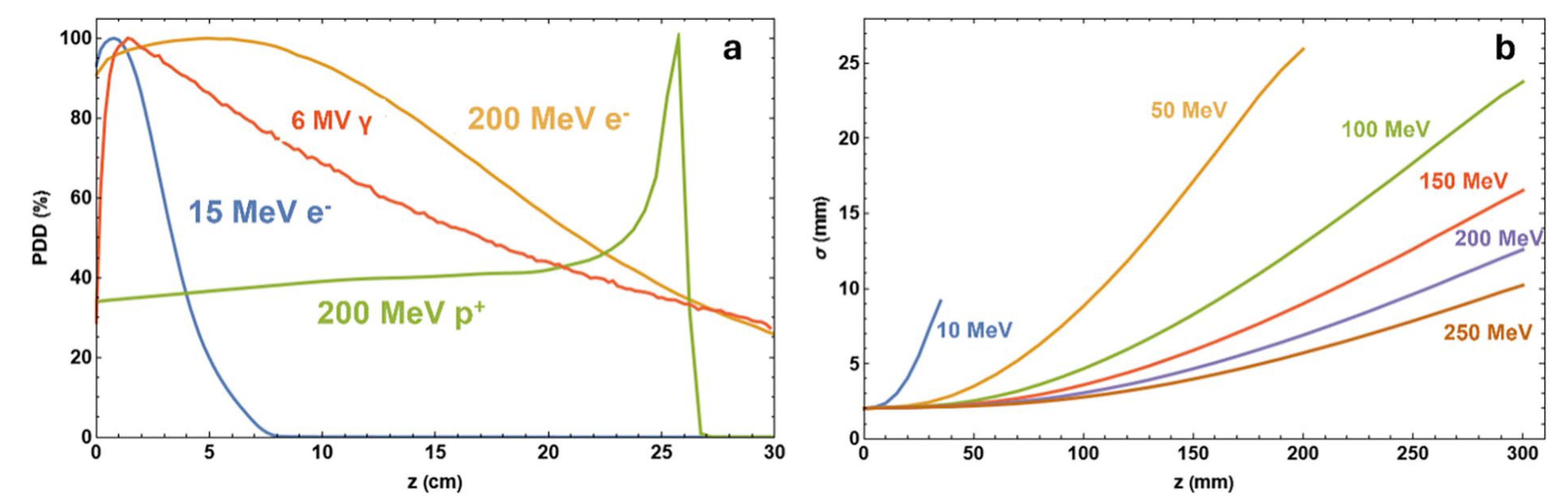
Figure 3.
The electron beam accelerator setup of energy 128.3 MeV, with photocathode, RF-gun and 2 S-band cavities housed in a solenoid each one. The total injector has 9.5 m length.
Figure 3.
The electron beam accelerator setup of energy 128.3 MeV, with photocathode, RF-gun and 2 S-band cavities housed in a solenoid each one. The total injector has 9.5 m length.
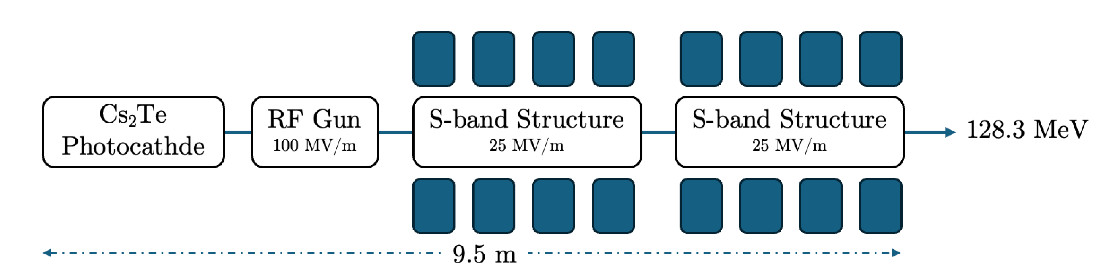
Figure 4.
a) The longitudinal electric field Ez (MV/m) vs the beam axis z(m), b) the solenoid field Bz (T), is shown as the black line, and the magnetic field gradient dBr/dr (T/m), is shown as the red line vs the beam axis z (m) at the injector, c) The electron beam transverse emittance vs the bam axis z (m) and d) The average electron beam energy to the final stage.
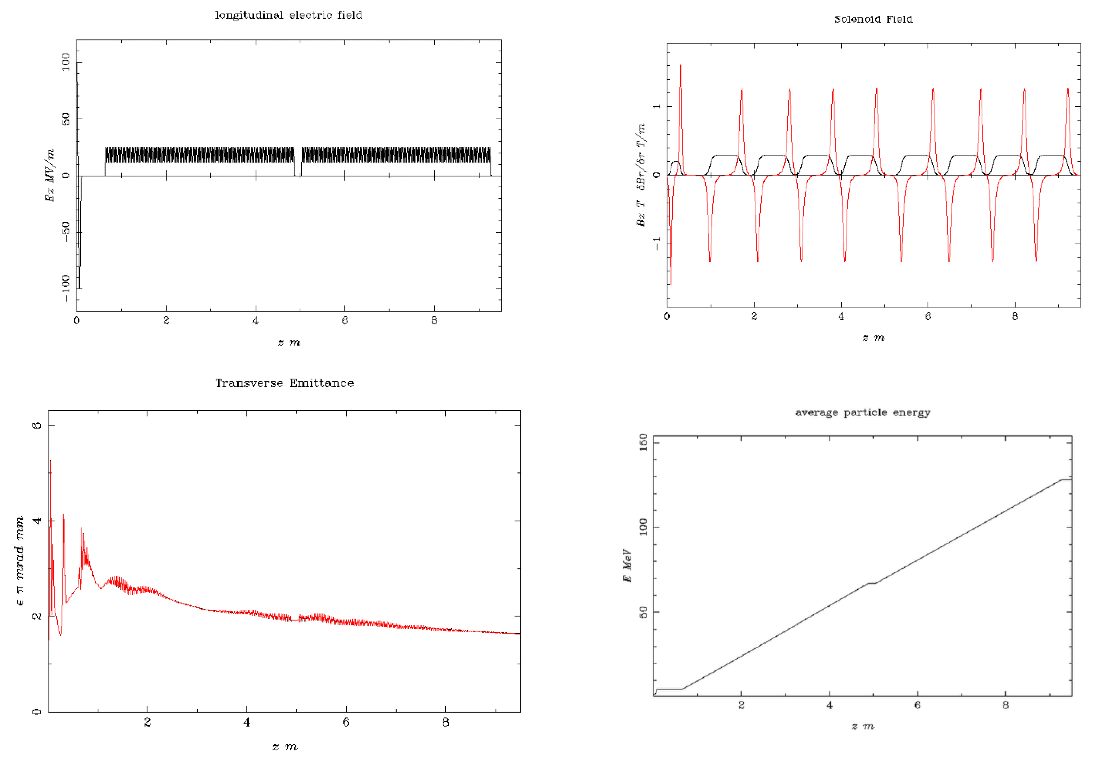
Figure 5.
The output beam distributions, are shown, in terms of transverse phase-space vs. z-axis (mm) and z-axis (mm) plus the transverse distribution vs. x-axis (mm) and y-axis (mm).
Figure 5.
The output beam distributions, are shown, in terms of transverse phase-space vs. z-axis (mm) and z-axis (mm) plus the transverse distribution vs. x-axis (mm) and y-axis (mm).
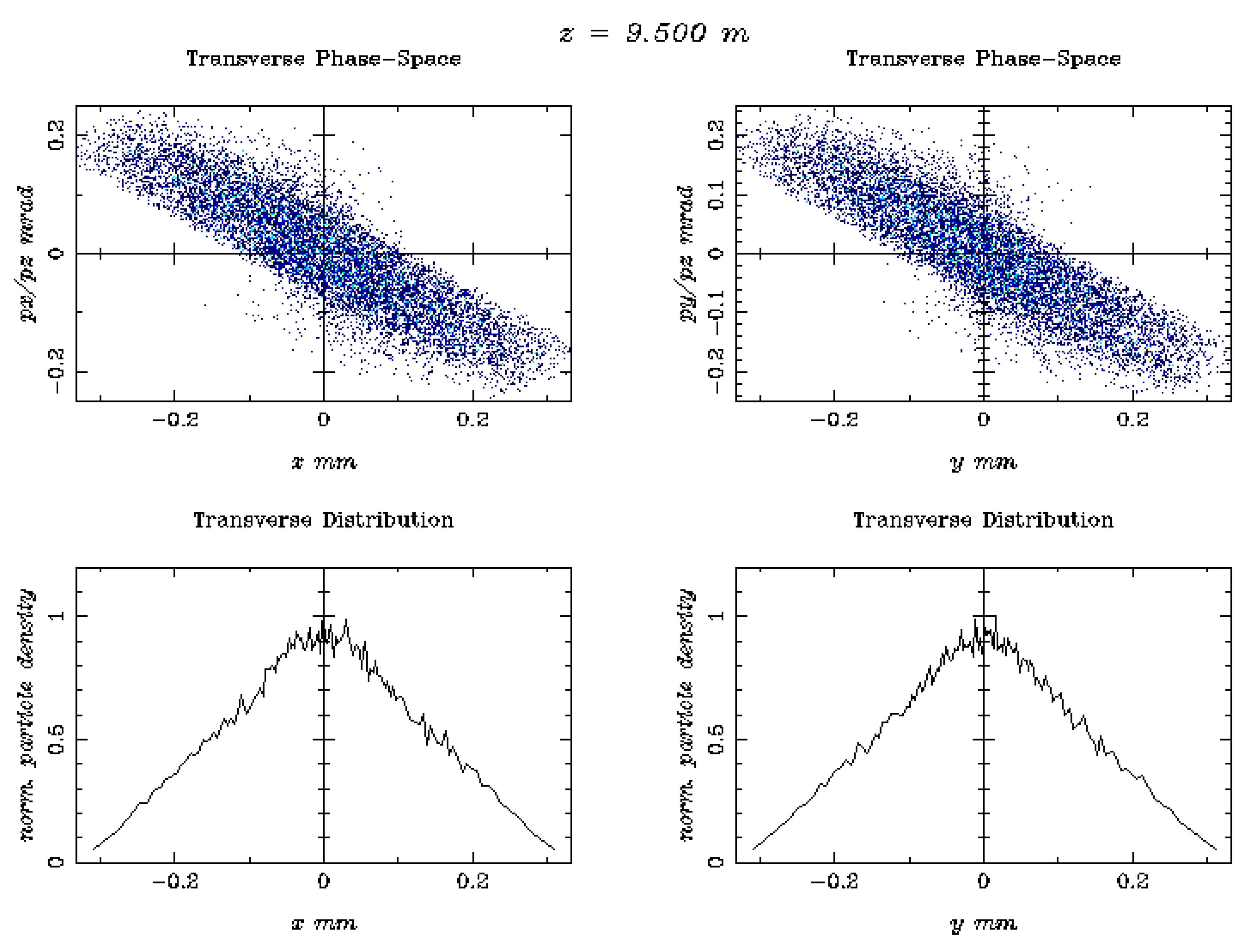
Figure 6.
The electron beam accelerator setup of energy 446.1 MeV, with photocathode, RF-gun and 2 S-band cavities housed in a solenoid each one plus four additional S-band structures. The total injector has 27.5 m length.
Figure 6.
The electron beam accelerator setup of energy 446.1 MeV, with photocathode, RF-gun and 2 S-band cavities housed in a solenoid each one plus four additional S-band structures. The total injector has 27.5 m length.
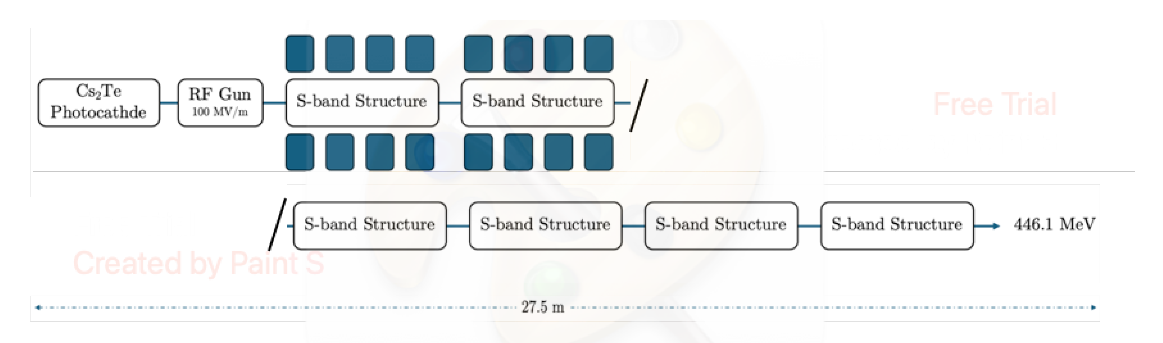
Figure 7.
a) The longitudinal electric field Ez (MV/m) vs the beam axis z(m), b) the solenoid field Bz (T), shown as the black line, and the magnetic field gradient dBr/dr (T/m), shown as the red line vs the beam axis z (m) at the injector, c) The electron beam transverse emittance vs. the bam axis z (m) and d) The average electron beam energy to the final stage.
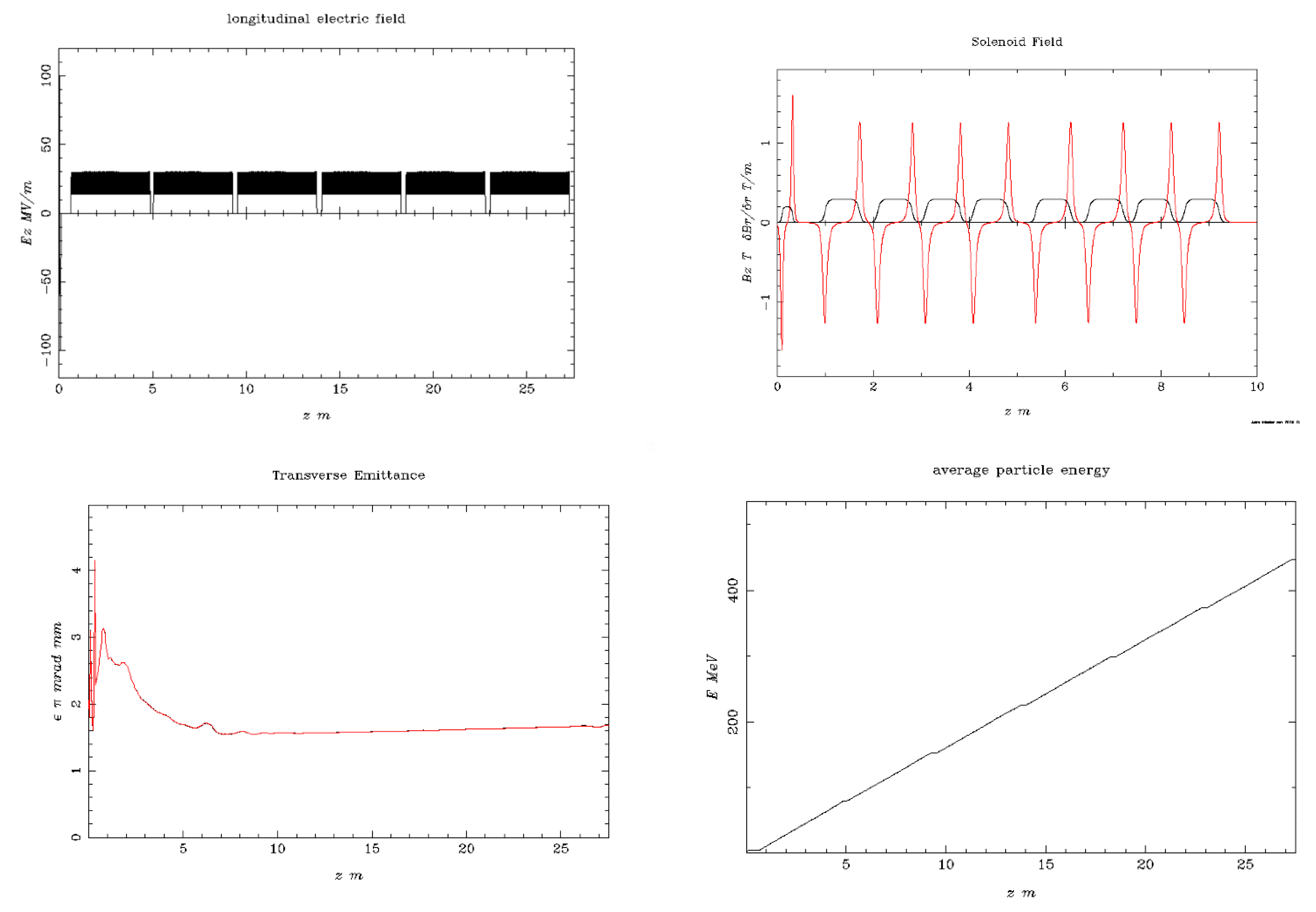
Figure 8.
The output beam distributions, are shown, in terms of transverse phase-space vs. z-axis (mm) and z-axis (mm) plus the transverse distribution vs. x-axis (mm) and y-axis (mm).
Figure 8.
The output beam distributions, are shown, in terms of transverse phase-space vs. z-axis (mm) and z-axis (mm) plus the transverse distribution vs. x-axis (mm) and y-axis (mm).

Figure 9.
Simulation 2D dose distribution plots by FLUKA code, using a range of electron energies, including 50, 100 MeV, and 1.2 GeV. It is underlined that the phantom dimension has been increased along the z-axis to 140 cm for the case of the 1.2 GeV beam energy [2].
Figure 9.
Simulation 2D dose distribution plots by FLUKA code, using a range of electron energies, including 50, 100 MeV, and 1.2 GeV. It is underlined that the phantom dimension has been increased along the z-axis to 140 cm for the case of the 1.2 GeV beam energy [2].

| Beam Characteristics | Conventional RT | FLASH RT |
|---|---|---|
| Dose Per Pulse | ~0.4 mGy | ~1 Gy |
| Dose Rate | ~102 Gy/s | ~105 Gy/s |
| Mean Dose Rate | ~0.1 Gy/s | ~100 Gy/s |
| Total Treatment Time | ~days/minutes | <500 ms |
Table 2.
Major key parameters for European VHEE beam facilities [19].
Table 2.
Major key parameters for European VHEE beam facilities [19].
| Beam Parameter | CLARA | CLEAR | ARES | SAFEST |
|---|---|---|---|---|
| Energy Range (MeV) | 50-250 | 60-220 | 59-155 | 80-100 |
| Bunch Charge (nC) | 0.005-0.25 | 0.01-1.5 | 0.00001-0.2 | 200 |
| Relative Energy | 0.01% (low | <0.2% | 0.039% | 0.2% |
| Spread | charge) | |||
| 0.1% (high | ||||
| Charge) | ||||
| Pulse Repetition | 1-100 | 0.8-10 | 1-50 | 100 |
| Frequency (Hz) | ||||
| Micro-bunches per | 1 | 1-150 | 1 | n/a |
| Train | ||||
| Beam Exit Window | 250 μm Be | 100 μm (Al) | 50 μm (Ti) | n/a |
Table 3.
The ASTRA simulation results for laser and photocathode parameters to achieve the FLASH-RT electron beam conditions.
Table 3.
The ASTRA simulation results for laser and photocathode parameters to achieve the FLASH-RT electron beam conditions.
| Parameters | Unit | Value |
|---|---|---|
| Photocathode material | - | Cs2Te |
| RMS laser spot size (XY) | mm | 0.90 |
| Laser pulse duration | ps | 10.00 |
| Laser rise/fall time | ps | 7.00 |
| Laser wavelength | nm | 262.0 (UVC) |
| Laser photon energy | eV | 4.73 |
| Initial kinetic energy | eV | 1.61 |
| Beam charge | nC | 1.00 |
| Electric field at cathode | MV/m | 99.00 |
| Energy distribution | Isotropic | |
| Longitudinal distribution | Uniform Ellipsoid | |
| Transverse distribution Radial |
Disclaimer/Publisher’s Note: The statements, opinions and data contained in all publications are solely those of the individual author(s) and contributor(s) and not of MDPI and/or the editor(s). MDPI and/or the editor(s) disclaim responsibility for any injury to people or property resulting from any ideas, methods, instructions or products referred to in the content. |
© 2025 by the authors. Licensee MDPI, Basel, Switzerland. This article is an open access article distributed under the terms and conditions of the Creative Commons Attribution (CC BY) license (http://creativecommons.org/licenses/by/4.0/).
Copyright: This open access article is published under a Creative Commons CC BY 4.0 license, which permit the free download, distribution, and reuse, provided that the author and preprint are cited in any reuse.


