
Submitted:
08 August 2025
Posted:
08 August 2025
You are already at the latest version
Abstract
Background/Objectives: Auricular epitheses play a vital role in restoring facial symmetry and patient confidence following congenital or acquired defects. Traditional wax-based fabrication is labor-intensive and lacks reproducibility. This study proposes and evaluates a simplified, digitally driven workflow for auricular prosthesis manufacturing, integrating virtual patient creation, mirrored ear design, and three-part mold fabrication using two design platforms—CATIA V5R21 (industrial CAD) and Blender (open-source graphics software). Key outcomes include mold reusability, patient-centered evaluation, and workflow feasibility; Methods: A 28-year-old female patient with right-sided microtia was selected. A light-based 3D facial scan was performed, and the intact contralateral ear was mirrored and adapted virtually to the defect site. Molds were designed in both CATIA and Blender using a standardized three-parallelepiped approach and printed using FDM technology (Elegoo Neptune 4 Plus). Five silicone epitheses were fabricated with each mold. Surface trueness was evaluated with Geomagic Control X, while subjective assessments were conducted by an independent prosthetic team and the patient using Visual Analogue Scales (VAS); Results: Both design workflows resulted in clinically usable prostheses. No statistically significant difference in RMS deviation was observed (p = 0.53), although CATIA-derived epitheses achieved higher subjective scores (mean 9.22/10) compared to Blender (mean 7.67/10). The preferred prosthesis (CATIA #4) was selected for final pigmentation and delivery. All molds were reused five times without structural damage; Conclusions: This study demonstrates that both CATIA and Blender can support an effective, patient-centered digital workflow for auricular prosthesis fabrication. The methodology enables reproducibility, mold reusability, and improved clinical accessibility of custom prosthetics.
Keywords:
auricular prosthesis
; digital workflow
; virtual patient
; facial scanning
; 3D printing
; patient-center evaluation
; Catia
; Blender
1. Introduction
Auricular soft prostheses (epitheses) restore the form and symmetry of a missing or malformed external ear, improving patients’ appearance and quality of life. Traditionally, fabricating a silicone auricular prosthesis is a labor-intensive, analog process reliant on skilled anaplastologists to sculpt wax patterns and create molds by hand [1]. This workflow involves numerous manual steps that are susceptible to human error and may result in surface irregularities or inconsistencies. Furthermore, these procedures are highly repetitive yet lack reproducibility, as each mold is individually crafted and cannot be reused or adapted for other patients, limiting standardization and scalability. These conventional methods often require multiple patient visits for impressions, try-ins, and adjustments, and they can be time-consuming and costly [2].
Recent years have witnessed a marked and inspiring step toward the integration of digital workflows—encompassing 3D imaging, computer-aided design/manufacturing (CAD/CAM), and additive manufacturing—as a means to enhance the precision and efficiency of auricular prosthesis fabrication. Digital techniques promise improved accuracy (by mirroring the patient’s intact ear anatomy), reduced fabrication time, and the possibility of remote or decentralized prosthetic care [2,3]. Moreover, once a digital workflow is established, verified, and successfully implemented, it can be efficiently reapplied and customized to suit the unique anatomical and clinical requirements of each individual patient, thereby increasing consistency and streamlining future prosthesis fabrication.
Several studies have described fully digital or hybrid approaches for auricular prosthesis fabrication, incorporating advanced data acquisition and modern CAD tools to streamline the process [1,4]. Despite the promising evolution of these workflows, limitations remain—particularly regarding knowledge, cost, accessibility, clinical usability, and reproducibility. Moreover, few studies systematically integrate patient feedback during the design phase or validate the fit and morphology of the final prosthesis using objective tools. In this context, we propose a simplified, predictable, easy to follow, and cost-effective hybrid workflow that combines digital design with conventional silicone processing to fabricate an auricular epithesis in a two-visit protocol. The workflow integrates:
- Minimally invasive data acquisition using structured-light scanning and processing;
- Virtual patient creation and mirroring of the contralateral ear;
- Precise adaptation and positioning of the mirrored ear to the defect site;
- Virtual visualization and incorporation of patient approval and feedback before final fabrication;
- Digital mold design using open-source or commercial engineering CAD, allowing for a balanced approach between cost and functionality.
- Conventional prosthesis manufacturing with medical-grade silicone, followed by manual extrinsic color customization for a better resemblance with a natural ear, that leads to a great comfort for the patient.
2. Materials and Methods
2.1. Clinical Scenario
This proof-of-concept workflow is illustrated through the treatment of a 34-year-old female patient presenting with unilateral microtia affecting the right side. The external auditory canal is anatomically present and covered by a thin epithelial layer, which permits functional hearing despite the absence of the auricle. The residual malformed external ear had been surgically removed during early childhood, prior to prosthetic rehabilitation.
At the time of presentation, the patient had been wearing a conventional standard silicone auricular epithesis for over five years. The prosthesis exhibited in time a significant degradation, including loss of elasticity and poor marginal positioning and adaptation. As a result, it required the application of excessive adhesive for daily retention. Additionally, exposure to water—such as during hair washing at a salon—often led to unintentional detachment. The patient’s main concerns included the unaesthetic appearance of the prosthesis, its hardened consistency, and discomfort during the use of over-ear headphones. Written informed consent was obtained from the patient for the entire clinical and digital workflow, including the use of images and data for research and publication purposes.
2.2. Digital Workflow Overview
The following steps outline the digital workflow employed for the design and fabrication of the auricular prosthesis.
2.2.1. Data Acquisition
Three-dimensional (3D) facial scanning was performed using a structured-light, light-based scanning system (Revopoint POP 2, Revopoint 3D Technologies Inc., Shenzhen, China), which captures data using an infrared structured light source and a dual-camera system. The scanner operates at a single-frame precision of up to 0.05 mm and a capture speed of up to 10 frames per second. Scans were acquired using the manufacturer’s proprietary software (Revo Scan), which was also used to align and reconstruct the 3D models.
Five 10 mm scan markers (consisting of a 6 mm white center and a 4 mm black border) were strategically placed on the subject’s face to facilitate accurate alignment and stitching during facial scanning. The markers were centered on the following anthropometric landmarks: subnasale, pogonion, glabella, and the left and right tragus. In addition, four radiopaque reference markers were applied to the defect side to enhance the accuracy of scan registration and spatial alignment in the area of interest.
The scanning procedure was performed under standardized conditions, with the subject maintaining a fixed head position and a horizontally aligned visual axis, ensuring that the Frankfort horizontal plane was parallel to the floor, in a uniformly illuminated environment. Illumination was provided by two Haiser Softbox units (6500K, 1200 lumens, Haiser, Germany). To ensure accuracy and prevent motion artifacts, the subject remained completely still throughout the scan, while the operator carefully maneuvered the scanning device around the head.
The resulting 3D mesh file was exported in PLY (Polygon File) format for further processing.
In addition, a photograph of the defect side and the contralateral healthy ear was taken under same standardized lighting conditions to support intrinsic silicone pigmentation matching during the final prosthesis fabrication. This visual reference was used to replicate skin tone, hue, and subtle surface details, ensuring optimal esthetic integration.
2.2.2. Digital Design of the Auricular Epithesis
Although Exocad DentalCAD does not offer a dedicated module for maxillofacial prosthetics, several core and optional modules can be effectively repurposed for the design of auricular epitheses. The following workflow outlines the step-by-step digital design process, highlighting the key modules and tools used. In this context, the software environment also supports the creation of a virtual patient, allowing for the superimposition of surface scan data (facial or intraoral scans) with Cone Beam Computed Tomography (CBCT) datasets, particularly in cases involving implant-supported epitheses. However, in the present case—where no osseointegrated implants were placed—CBCT imaging was not necessary, and all planning and design steps were completed based solely on high-resolution surface scanning and anatomical reference points.
The 3D facial scan of the patient, acquired in PLY format, was imported into Exocad DentalCAD 3.1 Rijeka (Exocad dental CAD, Darmstadt, Germany) using the DentalCAD Design module (Figure 1 a-c). This module, primarily developed for the design of dental restorations, was repurposed here to create a stable and controlled digital environment for the visualization and alignment of facial geometry. Orientation was achieved by referencing anatomical planes, aligning Camper’s plane — defined by the line connecting the inferior border of the ala of the nose to the superior border of the tragus of the ear— parallel to the digital horizontal (xy) plane.
The healthy (contralateral) ear was isolated and mirrored using the Mirror tool available in the alignment interface of Exocad. This generated a symmetrical copy, which was positioned on the defect side of the face. Due to noticeable facial asymmetry, the mirrored ear was uniformly reduced by 10% using the global scaling function within the Freeform tools (Expert Mode), to better match the spatial proportions and contour of the defect side.
Using Expert Mode, the mirrored ear was manually aligned to match the estimated natural position of the missing ear. Anatomical landmarks such as the tragus, orbital rim, and zygomatic arch were used as visual references to guide orientation and angulation. The following anthropometric criteria were considered during alignment: the superior pole of the ear was positioned to correspond with the superior tarsal crease, and the inferior lobule was aligned with the subnasale. The helical rim was set to protrude 1 to 2 cm from the scalp at an auriculocephalic angle of approximately 25°. Additionally, the long axis of the ear was tilted posteriorly by about 20° from the vertical to reflect natural anatomical inclination [5]. Due to facial asymmetry, minor scaling and positional adjustments were made to optimize aesthetic integration on the defect side.
The margin of the future epithesis was carefully delineated directly on the facial model using the Margin Lines function within the DentalCAD Design module. Although primarily intended for defining preparation lines in dental restorations, this tool enabled precise control over the outline of the ear prosthesis relative to the intended skin contact area.
Anatomical refinements were performed using the Freeform Sculpting tools available within the Full Denture module. Surface smoothing, margin softening, and anatomical detail correction were applied. The margins were gradually thinned to approximately 0.1 mm to create a seamless transition between prosthesis and skin.
The ear design, along with the facial scan, was initially saved in HTML format using Exocad’s built-in viewer export function. This format allows for easy visualization of the 3D design on any device, including smartphones and tablets, without the need for specialized software (Figure 2). The HTML file was shared with the entire prosthetic team and the patient to facilitate remote viewing, interdisciplinary communication, and esthetic validation. After receiving approval and confirming the proposed design, the finalized model was saved and exported in STL (Stereolithography) format, which is compatible with 3D printing technologies and mold design software. The STL file served as an input for subsequent mold generation and physical prosthesis fabrication.
2.2.3. Digital Mold Design Using Meshmixer and CATIA V5R21
After finalizing the design of the auricular epithesis in Exocad and exporting the model as an STL file, the file was first imported into Meshmixer (Autodesk Inc.) to verify mesh integrity, correct surface artifacts, and establish an optimal orientation for mold creation. Meshmixer was also used to visualize potential undercuts and adjust the model’s rotation to facilitate future splitting for mold fabrication (Figure 3).
Once the geometry was cleaned and properly oriented, the STL file was imported into CATIA V5R21 (Dassault Systèmes), where a complete three-part mold was developed using a combination of specialized workbenches: Quick Surface Reconstruction, Core & Cavity Design, Generative Shape Design, Part Design and STL Rapid Prototyping.
The process starts by importing the points cloud into Quick Surface Reconstruction workbench and perform an Automatic Surface recognition. The main purpose of this important step is to obtain a closed surface and convert it into a solid. Figure 4 presents the parameters used with Automatic Surface tool such as Mean surface deviation of 0.1 mm with a Surface detail of 500 and a Target ratio of 95.
Moving to the Part Design workbench allowed the authors to convert the obtained surface into a solid which will be used to create the cores and the cavities of the mold. The solid is shown in Figure 4 together with the parting lines.
For a simple part it is convenient, in most cases, to have a single parting line which splits the solid into two parts, the core and the cavity, having the pulling direction along the Z axis. But this ear model is more than a simple one, with complex surfaces which make the task of creating the parting line very difficult. That’s why a new pulling direction is added along the Y axis. Once the second pulling direction was added this makes the mold to be a three-component assembly.
The parting line along the Z axis is computed in the Core & Cavity Design workbench in CATIA V5R21. The result of this computation is presented in Figure 5. Because of the complexity of the part, CATIA V5R21 generates more parting lines for each direction, so there should be extracted the appropriate one, as in Figure 5.
In the analysis that CATIA V5R21 performed when computed the parting line, the undercuts along the Z axis direction were shown colored brown in Figure 6. The size of the undercut area was also the reason why the second pulling direction was needed.
Following the same procedure for the second pulling direction, the authors obtained the results shown in Figure 7.
Regarding the parting line along the Y axis, it is more complex than the one along the Z axis and it was a quite modeling challenge to extract the appropriate curves which would form the final parting line along the specified axis.
In order to be able to open the mold, the parting line needed to be adjusted and completed by adding two sketches as in Figure 8.
To create the components of the mold a surface was obtained based on the curves in Figure 6 and the sketches in Figure 8.
Once the parting lines are computed and adjusted, Generative Shape Design workbench was used to create the surfaces which were considered when splitting a parallelepiped to create the three-component mold. The surfaces obtained this way are presented in Figure 9.
The next step in the process was to create the three-component mold by using Part Design workbench and the previously created surfaces and the solid.
There were created three bodies in the shape of a parallelepiped, and it was applied three times a boolean operation of Remove to subtract a 3D solid indicated in Figure 9 from each body. Then, the surfaces indicated in Figure 8 were used to split and keep the appropriate solid body of the mold. To ensure the orientation of the components of the mold between each other there were added two spheres on each two components. The components of the mold are presented in Figure 10. The very good quality of the surfaces can be observed, which will be transmitted to the physical model (prosthesis).
The final step was to prepare the mold components for additive manufacturing by exporting them into the STL format. To achieve this goal, the STL Rapid Prototyping workbench of CATIA V5R21 was used. For each of the components was applied a Tessellation operation with the Sag parameter of 0.02 mm (which is the maximum distance between the triangles and the geometry), as seen in Figure 11.
2.2.4. Digital Design of a Three-Part Mold in Blender
The final auricular epithesis design, exported in STL format from Exocad, was directly imported into Blender 3D (version 4.4.3) for mold generation. A three-part mold was constructed using simple parallelepiped (cube) primitives, manipulated via Boolean operations. This mesh-based modeling strategy enabled accurate negative reproduction of the ear anatomy and ensured compatibility with standard 3D printing processes.
Base Mold Component (Cube 1 – Contact Surface Block): The first parallelepiped was added and precisely aligned with the posterior base of the ear, corresponding to the surface that would contact the patient’s skin on the defect side (Figure 12). This component formed the bottom mold, providing foundational support during casting and orienting the model within the mold geometry. Its shape enclosed the lower part of the ear, ensuring mechanical stability and ease of demolding.
Posterior Mold Component (Cube 2 – Angled Block): The second parallelepiped was introduced and rotated to match the natural auriculocephalic angle (25°), simulating the outward projection of the ear from the skull. Positioned to cover the posterior and superior aspects of the ear (including the helix), this block enabled an anatomically driven mold segmentation, while minimizing undercuts (Figure 13). Cube 2 was subtracted from the first cube using the Boolean Difference modifier to define precise interfacing surfaces.
Anterior Mold Component (Cube 3 – Upper Parallel Block): The third parallelepiped was aligned parallel to the base mold (Cube 1) and placed above it to enclose the anterior and lateral surfaces of the ear, including the antihelix, tragus and conchal area (Figure 14). It completed the upper segment of the mold and was shaped through Boolean subtraction against the previous blocks to ensure a seamless fit and proper mold closure. After applying the Boolean operations, several loose parts were observed—fragments generated during mesh subtraction that remained associated with Cube 3. These were corrected by selecting all related parts and applying the Object → Join function, resulting in a clean, unified mold component ready for export.
Each of the three mold parts was finalized using the Boolean Difference modifier with the ear STL model acting as the subtracting object. Uniform trimming of the external borders was performed using an auxiliary bounding cube to ensure clean and printable edges. The resulting mold components were separated using the 'Separate by Loose Parts' command, checked for mesh integrity in Solid View mode, and individually exported in STL format for high-resolution 3D printing.
2.2.53. D Printing of the Molds and Ear Prosthesis Manufacturing
Both three-part mold sets were printed simultaneously using PLA filament (eSUN, Shenzhen, China) and high-resolution settings, ensuring dimensional accuracy and internal surfaces appropriate for silicone casting. Printing was performed using the Elegoo Neptune 4 Plus, a high-speed Fused Deposition Modeling (FDM) 3D printer (Figure 15 a and b).
The final ear prosthesis was fabricated using Maxillofacial Silicone M511 (Technovent, Bridgend, UK), mixed in a 10:1 ratio by weight (Part A to Part B). The silicone was intrinsically pigmented to match the patient’s skin tone around the defect area prior to mixing. After thorough blending, the material was degasified under vacuum for 20 minutes to eliminate air bubbles.
The degassed silicone was carefully injected into each of the 3D-printed molds—designed via CATIA V5R21 and Blender workflows—and excess material was extruded through gentle manual pressure. The assembled molds were placed in an incubator at 100 °C and polymerized for one hour under mechanical pressure, following the manufacturer’s recommendations.
To assess reproducibility and consistency, a total of ten silicone ear prostheses were fabricated—five using the CATIA V5R21-generated mold and five using the Blender-generated mold. In each case, the same mold was reused for five consecutive castings without structural damage or deformation, demonstrating its durability and suitability for small-series production. The ability to reuse the 3D-printed molds for at least five cycles fulfilled the clinical requirements for auricular prosthetic fabrication, as multiple prostheses are often needed—for example, seasonal variants (summer and winter) to accommodate changes in skin tone or perspiration levels, or replacement units in the event of loss or damage. This reusability supports cost-effective, rapid reproduction of the prosthesis without repeating the mold-making process.
After curing, the silicone elastomer prostheses were removed from the molds and carefully trimmed to eliminate irregular or thin margins. Prior to extrinsic pigmentation, all prostheses were compared to evaluate surface quality, anatomical detail retention, and adaptation to the defect site through both objective and subjective analysis. Final extrinsic coloration was applied only to the prosthesis selected by the patient as the most suitable, based on combined clinical evaluation and personal preference, in order to reproduce fine skin details and ensure optimal aesthetic integration with the surrounding facial tissue.
2.2.6. Objective and Subjective Evaluation of the Final Prostheses (Prior to Extrinsic Pigmentation)
To compare the performance of the two mold fabrication workflows (CATIA V5R21 vs. Blender), both objective and subjective evaluation methods were applied:
Objective Evaluation
Surface trueness and dimensional accuracy of each prosthesis were assessed using 3D mesh analysis in Geomagic Control X (3D Systems, Rock Hill, SC, USA). Scanned models of the final silicone ears were superimposed onto the corresponding original STL design file. Root Mean Square (RMS) deviation values and color map deviation analysis were calculated to quantify discrepancies between the planned and fabricated models. Additionally, to assess consistency and material use, each prosthesis was weighed using a calibrated digital scale, at room temperature.
Subjective Evaluation
An independent prosthetic team (not involved in the mold design phase) evaluated each prosthesis based on surface texture, anatomic detail reproduction, ease of demolding and finishing. The evaluation used a 10-point Visual Analogue Scale (VAS), where 1 represented “not suitable for clinical use” and 10 indicated “ideal for use.”
The patient was also invited to assess both prototypes, rating perceived esthetics (including shape, contour, and color match), comfort and fit, and overall preference. Each criterion was scored using the same 10-point Visual Analogue Scale (VAS), with 10 indicating the highest preference and closest similarity to the patient’s natural ear shape and color.
The subjective evaluation was conducted in a blinded manner: both the independent prosthetic team and the patient were unaware of which software (CATIA or Blender) was used to generate each mold.
Statistical analysis
The root mean square (RMS) deviation values were analyzed to compare the accuracy of auricular epitheses produced using Catia- and Blender-designed molds using IBM® SPSS® version 25.0 (IBM Corp., Armonk, NY, SUA) software. Normality of the data was assessed using the Shapiro-Wilk test, and homogeneity of variances was evaluated with Levene’s test. As both assumptions were met, an independent samples t-test was applied to determine statistical significance between the two groups. A significance level of p < 0.05 was used for all analyses.
3. Results
Both the CATIA V5R21-based and Blender-based mold designs enabled the successful fabrication of clinically usable silicone auricular prostheses. While all prostheses met the essential criteria for anatomical fidelity, retention, and adaptation to the defect site, minor imperfections were noted in some units, such as small air bubbles or surface irregularities. These were correctable and did not compromise clinical applicability. Overall, the patient and prosthetic team confirmed that all prostheses were suitable for clinical use, although not all achieved an ideal finish without adjustment.
Figure 16 illustrates the ten final silicone prostheses fabricated using each mold design.
As no dedicated software was available for the design of maxillofacial prostheses [6], two different programs were employed: one industrial-software solution (CATIA V5R21) and one open-source computer graphics software (Blender). A comparative summary of the two mold design workflows is presented in Table 1.
Objective Evaluation
Trueness Analysis:
The 3D scans of the silicone prostheses were compared to the original STL design using metrology software Geomagic Control X.
RMS deviation values ranged from a mean of 0.41 (± 0.08) mm, [max. 0.52 mm – min. 0.33 mm] (CATIA V5R21) to 0.44 (± 0.05) mm, [max. 0.50 mm – min. 0.37 mm] (Blender), both within acceptable clinical tolerances for auricular epitheses. No statistically significant difference was observed in RMS values between the epitheses fabricated using CATIA- and Blender-designed molds (p = 0.53). A boxplot illustrating the RMS deviation by software platform (CATIA vs. Blender) is presented in Figure 17, highlighting the distribution, median, and variability of RMS values within each group.
Color map deviation analysis showed that over 90% of the surface area fell within ±0.3 mm of the reference geometry in both cases (Figure 18 a and b).
Weights of the Fabricated Ears
The mean weight of the ear prostheses fabricated using the CATIA-designed mold was 13.69 g (±0.48), with a maximum of 14.26 g and a minimum of 13.16 g. In comparison, prostheses fabricated using the Blender-designed mold had a mean weight of 12.74 g (±0.51), with a maximum of 13.28 g and a minimum of 12.18 g. These values were compared to the estimated mean weight of a natural human ear, calculated from the STL model using a cartilage density of 1300 kg/m³ [7]. The estimated weight was computed using CATIA’s material assignment function by converting the STL mesh into a solid model and associating it with a material of known density. This process yielded an estimated mass of 0.01446 kg (14.46 g), as illustrated in Figure 20.
The calculated mass of the natural ear (14.46 g) closely approximates the measured weights of the fabricated silicone prostheses, particularly those manufactured using the CATIA-designed mold (mean 13.69 g). This similarity suggests that the prostheses exhibit a weight profile comparable to the patient’s own ear, contributing to improved comfort and natural feel during daily wear.
Subjective Evaluation
Subjective assessments were conducted by an independent prosthetic team and the patient. The expert team rated each prosthesis on surface texture, anatomical detail, and ease of demolding/finishing using a 10-point Visual Analogue Scale (VAS), with CATIA-based prostheses achieving a higher average score (9.22/10) compared to those designed with Blender (7.67/10). The patient evaluated all ten prostheses based on esthetics, comfort, and overall preference, selecting CATIA prosthesis no. 4 as the preferred design (10/10). The mean VAS scores assigned by the patient were 8.6/10 for CATIA and 6.8/10 for Blender. Detailed results are presented in Table 2.
The patient’s preferred prosthesis was number 4, which was provided to the prosthetic team for extrinsic pigmentation prior to final delivery. The try-in with the selected epithesis is shown in Figure 21.
4. Discussion
This proof-of-concept study presents a streamlined, reproducible, and cost-effective hybrid workflow for the fabrication of auricular epitheses, comparing two digital mold design strategies—one based on industrial CAD software (CATIA V5R21) and the other on open-source mesh modeling software (Blender). The primary aim was to evaluate the accuracy, usability, and subjective acceptability of both workflows in a real clinical case.
Our findings support previous evidence that digital workflows can significantly improve the efficiency and reproducibility of auricular prosthesis fabrication compared to traditional manual methods. By incorporating structured-light scanning, virtual design, and three-part mold generation, this protocol eliminates the need for physical impressions and minimizes patient discomfort and clinical time. This aligns with prior studies advocating for the digitalization of maxillofacial prosthodontics to enhance patient-centered care [1,4,8,9,10,11,12,13].
While multiple studies have validated the feasibility of using digital tools in craniofacial prosthetics—including platforms such as Mimics, Freeform, or 3Shape—few directly compare open-source and proprietary CAD environments under similar clinical constraints [4,14,15]. Our investigation uniquely evaluates Blender and CATIA V5R21, offering quantifiable data and subjective feedback from both clinicians and patients.
The use of structured-light scanning combined with Exocad for mirroring and customizing the prosthetic ear enabled accurate virtual adaptation, leveraging anthropometric principles for aesthetic positioning [5,16].
Both digital mold design approaches—CATIA and Blender—yielded clinically acceptable silicone prostheses, demonstrating that open-source tools may serve as viable alternatives to expensive proprietary software when used by experienced operators. This confirms observations from published studies that emphasize the increasing accessibility of digital fabrication methods in prosthodontics [1,3,6].
Previous literature (Bos et al., 2015; Unkovskiy et al., 2019) has demonstrated sub-millimeter accuracy in mold fabrication, with mean deviations as low as 0.8 mm using advanced CAD tools such as Rhinoceros and Mimics [[3,16,17]. Our findings are consistent, with RMS deviation remaining within clinically acceptable limits for both CATIA and Blender-generated molds, with a maximum of 0.52 mm. The absence of a statistically significant difference in RMS (p = 0.53) further supports the interchangeability of the two platforms from a dimensional accuracy standpoint. However, subjective expert ratings and patient preference indicate that molds designed using CATIA yielded prostheses that were rated higher in terms of anatomical fidelity and surface quality. The fact that over 90% of surface deviation in both cases remained within ±0.3 mm further validates the clinical viability of both digital workflows.
The calculated mass of the natural ear (14.46 g), based on assigning a cartilage density to the STL file of the model, closely approximates the measured weights of the fabricated silicone prostheses—particularly those manufactured using the CATIA-designed mold (mean 13.69 g). This similarity suggests that the prostheses exhibit a weight profile comparable to the patient’s own ear, which may contribute to enhanced comfort, a balanced feel, and natural integration during daily wear. In contrast, the Blender-designed prostheses exhibited a slightly lower average weight (12.74 g), mainly due to reduced marginal extensions caused by some breakage during demolding. These failures were attributed to undercuts present in the contact region between the mold and the prosthetic surface, which were more difficult to control using Blender. To the authors’ knowledge, this is the first study to perform such a weight comparison between silicone auricular prostheses and the estimated weight of the natural human ear.
Subjective evaluations revealed higher mean VAS scores for CATIA-based prostheses from both the expert team and the patient. This may reflect the higher parametric control and surface quality achievable with CATIA’s engineering tools. The ease of mold opening and finishing was consistently better with the CATIA mold, possibly due to the refined design of the parting surfaces and automated parting line generation. Blender, while flexible and intuitive, required more manual correction steps, increasing the potential for minor errors or misalignments. These findings highlight an important trade-off between software accessibility and design precision.
Notably, the patient consistently preferred one of the CATIA-derived prostheses, both in terms of comfort and anatomical realism. This preference aligns with the minor trueness advantage and smoother surface morphology noted in the objective analysis. Importantly, however, all ten prostheses (from both workflows) were deemed suitable for clinical use, confirming the effectiveness of the hybrid approach in producing high-quality, reproducible outcomes.
The reusability of each 3D-printed mold up to five times without loss of detail or structural integrity offers substantial advantages in cost reduction and time efficiency. Previous literature rarely addresses mold durability and reusability; thus, our results contribute novel practical insights to the field.
With a robust mold on hand, new prostheses can be fabricated on demand without needing to re-design or re-print a mold each time. Our results confirmed that the printed mold maintained its accuracy and integrity over multiple casting cycles, with no observable distortion in the prosthesis dimensions. This outcome is consistent with reports by Ballo et al. and others, who note that molds produced by vacuum casting or high-resolution printing can be reused for multiple silicone pours without significant loss of dimensional accuracy [18]. By eliminating the need to print a fresh mold for each prosthesis, the overall workflow becomes more cost-effective once the initial mold is made. It also enables quicker fabrication of backup or replacement prostheses for the patient if needed (e.g. in case of damage), thereby improving long-term care.
In fabricating the mold itself, we carefully considered the choice of 3D printing technology. Stereolithography (SLA) and digital light processing (DLP) printers can produce molds with very high resolution and smooth surfaces – an attractive feature since the silicone will capture fine surface details from the mold [3,19,20]. Indeed, if surface finish were the only concern, resin-based printing would be ideal; an SLA-printed mold yields a prosthesis with minimal visible layer lines or texture artifacts. However, a critical issue with photopolymer resin molds is the risk of silicone cure inhibition [21,22]. Most facial prostheses use platinum-catalyzed (addition-cure) silicones, whose curing process can be poisoned by certain chemicals found in standard 3D printing resins. Uncured acrylate residues and photoinitiators (the “photoreticular” agents in SLA/DLP resins) are known to inhibit platinum-based silicone catalysts. If the resin mold is not thoroughly post-cured and cleaned, the poured silicone may remain tacky or fail to set properly. This phenomenon – documented both anecdotally and in materials research – could compromise the fabrication of a prosthesis (leading to wasted material and time). To avoid this problem, we chose to print the mold using fused deposition modeling (FDM) with PLA filament, a thermoplastic method that does not rely on UV-curing chemistry. The inert nature of FDM plastics ensured complete compatibility with our silicone; we encountered no curing issues when casting the prosthesis. The trade-off is that FDM printing produces a somewhat rougher surface. Layer striations were visible on the inner mold walls, and these translated into minor texture on the silicone prosthesis. In our case, this was not a major issue, as it could be addressed during extrinsic pigmentation and finishing. However, it was the main reason for the lower subjective evaluation scores. It is worth noting that many researchers still favor SLA/DLP for mold-making and have developed protocols to mitigate cure inhibition – for example, aggressive UV post-curing, solvent cleaning, or applying an inert coating to the mold. These procedures must be carefully applied to avoid compromising biocompatibility or introducing cytotoxic components. Another possible approach is using polyJet or other 3D printing materials specifically designed to be silicone-compatible, though those can be costly [23,24]. Given our resources and the specific silicone (with a platinum–“silver” catalyst) used in this project, FDM offered a reliable and cost-effective solution. In summary, while SLA/DLP printing provides superior smoothness and detail (benefiting the prosthesis aesthetics), FDM printing was justified in our workflow to ensure chemical compatibility and avoid cure inhibition problems [25,26,27]. This decision underscores an important practical point in digital prosthodontics: the choice of fabrication method must consider material interactions, not just geometric precision. By selecting FDM, we prioritized a robust curing process for the silicone over the marginal gains in surface finish, a compromise that ultimately paid off in a successful prosthesis outcome.
One limitation of this study is its single-patient design, which limits generalizability. However, the protocol was intentionally tested under controlled conditions to isolate workflow differences and assess reproducibility across multiple prostheses. Future research should involve multicenter validation in larger cohorts, including implant-retained epitheses and variable defect types. Furthermore, integrating AI-based modeling or deep learning for automatic landmark detection and mold segmentation may enhance both precision and workflow automation [6].
5. Conclusions
This proof-of-concept study successfully demonstrated a hybrid, accessible workflow for the fabrication of auricular epitheses, integrating virtual patient design and mold creation using both commercial (CATIA) and open-source (Blender) software.
Both workflows enabled the creation of clinically functional prostheses, with good anatomical fit and favorable adaptation to the defect site. However, the CATIA-based approach resulted in superior surface fidelity and anatomical detail, as confirmed by both objective RMS deviation analysis and subjective assessments by experts and the patient.
While Blender allowed for faster modeling and greater accessibility due to its open-source nature, it presented challenges in terms of mesh precision and segmentation accuracy, requiring more manual intervention.
The proposed workflow, requiring only two patient visits, emphasizes cost-effectiveness, predictability, and customizability, suggesting that it may be easily adopted in various clinical and educational settings, particularly where high-end equipment is not available.
Future studies should include a larger patient sample and explore implant-retained designs and long-term outcomes to further validate the clinical applicability of this approach.
Author Contributions
Conceptualization, C.I.T., C.M.C., O.E.B.V. and I.G.G.; methodology, C.I.T., C.M.C., O.E.B.V., and I.G.G.; software, C.I.T., C.M.C., I.G.G.; I.D., I.M.B.; validation, C.I.T., C.M.C., O.E.B.V. and I.G.G.; formal analysis, C.I.T., C.M.C., O.E.B.V., I.G.G.; investigation, C.M.C., O.E.B.V.; resources, C.I.T.; data curation, C.I.T., C.M.C., O.E.B.V., I.G.G.; writing—original draft preparation, C.I.T., C.M.C., O.E.B.V.,I.T., I.M.B. and I.G.G.; writing—review and editing, C.I.T., C.M.C., O.E.B.V. and I.G.G.; visualization, C.I.T., C.M.C., O.E.B.V. and I.G.G.; supervision, C.M.C.; project administration, C.I.T., C.M.C.; funding acquisition, C.M.C. All authors have read and agreed to the published version of the manuscript.
Funding
This research received no external funding.
Institutional Review Board Statement
The study was conducted in accordance with the Declaration of Helsinki.
Informed Consent Statement
Written informed consent was obtained from the involved in the study.
Data Availability Statement
Data are available from the corresponding authors upon reasonable request.
Conflicts of Interest
The authors declare no conflicts of interest.
Abbreviations
The following abbreviations are used in this manuscript:
| CAD/CAM | computer-aided design/manufacturing |
| PLY | Polygon File |
| HTML | HyperText Markup Language |
| STL | Stereolithography |
| PLA | Polylactic Acid |
| FDM | Fused Deposition Modeling |
| VAS | Visual Analogue Scale |
| NURBS | Non-Uniform Rational B-Splines |
| STEP | Standard for the Exchange of Product model data |
| IGES | Initial Graphics Exchange Specification |
| OBJ | Object File |
| RMS | Root mean square |
| DLP | Digital light processing |
References
- Tarba, C.I.; Cristache, M.A.; Baciu, I.M.; Cristache, C.M.; Burlacu Vatamanu, O.E.; Oancea, L. Advancements in Digital Workflows for 3D-Printed Maxillofacial Soft Prostheses: Exploring Design and Materials in Direct Additive Manufacturing: A Scoping Review. Appl. Sci. 2025, 15, 1701. [Google Scholar] [CrossRef]
- Domingue, D.; Glenn, N.C.; Vest, A.; White, J.R. Osseointegrated implant-retained auricular prosthesis constructed using cone-beam computed tomography and a prosthetically driven digital workflow: a case report. Clin Case Rep. 2020, 9, 37–45. [Google Scholar] [CrossRef] [PubMed]
- Unkovskiy, A.; Spintzyk, S.; Axmann, D.; Engel, E.M.; Weber, H.; Huettig, F. Additive Manufacturing: A Comparative Analysis of Dimensional Accuracy and Skin Texture Reproduction of Auricular Prostheses Replicas. J. Prosthodont. 2019, 28, e460–e468. [Google Scholar] [CrossRef]
- Bi, Y.; Zhou, M.; Wei, H. Digital workflow for auricular prosthesis fabrication with a negative mold. J. Prosthet. Dent. 2024, 131, 1254–1258. [Google Scholar] [CrossRef]
- Pickrell, B.B.; Hughes, C.D.; Maricevich, R.S. Partial Ear Defects. Semin. Plast. Surg. 2017, 31, 134–140. [Google Scholar] [CrossRef] [PubMed]
- Cristache, C.M.; Tudor, I.; Moraru, L.; Cristache, G.; Lanza, A.; Burlibasa, M. Digital Workflow in Maxillofacial Prosthodontics—An Update on Defect Data Acquisition, Editing and Design Using Open-Source and Commercial Available Software. Appl. Sci. 2021, 11, 973. [Google Scholar] [CrossRef]
- Tanaka, E. Biomechanical and tribological properties of the temporomandibular joint. Front. Oral Maxillofac. Med. 2021, 3. [Google Scholar] [CrossRef]
- Cruz, R.L.J.; Ross, M.T.; Skewes, J.; Allenby, M.C.; Powell, S.K.; Woodruff, M.A. An advanced prosthetic manufacturing framework for economic personalised ear prostheses. Sci. Rep. 2020. [Google Scholar] [CrossRef]
- Ciocca, L.; Gastaldi, G. Restoration of Facial Defects with Digital Technology; Elsevier: London, UK, 2022; ISBN 9780323902953. [Google Scholar]
- Unkovskiy, A. Digital workflow of facial prostheses manufacturing, Freie Universität Berlin, 2022.
- Heydenrych, A.; van der Walt, J.G.; van den Heever, H.J. Auricular prosthesis positioning using virtual planning in combination with additive manufacturing. J. Stomatol. oral Maxillofac. Surg. 2023, 124. [Google Scholar] [CrossRef]
- MS, A.; EAESAEM, T. Digital Designing of a 3D-Printed Stackable Ear Mold for Auricular Rehabilitation: A Technical Note. Int. J. Prosthodont. 2023, 36. [Google Scholar] [CrossRef]
- Bannink, T.; Bouman, S.; Wolterink, R.; van Veen, R.; van Alphen, M. Implementation of 3D technologies in the workflow of auricular prosthetics: A method using optical scanning and stereolithography 3D printing. J. Prosthet. Dent. 2021, 125, 708–713. [Google Scholar] [CrossRef]
- Tanveer, W.; Ridwan-Pramana, A.; Molinero-Mourelle, P.; Forouzanfar, T. Applications of CAD/CAM Technology for Craniofacial Implants Placement and Manufacturing of Auricular Prostheses—Systematic Review. J. Clin. Med. 2023, Vol. 12, Page 5950 2023, 12, 5950. [Google Scholar] [CrossRef] [PubMed]
- Ballo, A.M.; Nguyen, C.T.; Lee, V.S.K. Digital Workflow of Auricular Rehabilitation: A Technical Report Using an Intraoral Scanner. J. Prosthodont. 2019. [Google Scholar] [CrossRef]
- McHutchion, L.; Aalto, D. Simulation of tissue-prosthesis margin interface by using surface scanning and digital design for auricular prostheses. J. Prosthet. Dent. 2020. [Google Scholar] [CrossRef] [PubMed]
- Cruz, R.L.J.; Ross, M.T.; Nightingale, R.; Pickering, E.; Allenby, M.C.; Woodruff, M.A.; Powell, S.K. An automated parametric ear model to improve frugal 3D scanning methods for the advanced manufacturing of high-quality prosthetic ears. Comput. Biol. Med. 2023, 162, 107033. [Google Scholar] [CrossRef] [PubMed]
- Manju, V.; Babu, A.S.; Krishnapriya, V.N.; Chandrashekar, J. Rapid Prototyping Technology for Silicone Auricular Prosthesis Fabrication: A Pilot Study. J. Head Neck Physicians Surg. 2021, 9, 35–40. [Google Scholar] [CrossRef]
- Mukhtarkhanov, M.; Perveen, A.; Talamona, D. Application of Stereolithography Based 3D Printing Technology in Investment Casting. Micromachines 2020, Vol. 11, Page 946 2020, 11, 946. [Google Scholar] [CrossRef]
- Zhang, J.; Hu, Q.; Wang, S.; Tao, J.; Gou, M. Digital Light Processing Based Three-dimensional Printing for Medical Applications. Int. J. Bioprinting 2020, 6, 12–27. [Google Scholar] [CrossRef]
- Totu, E.E.; Cristache, C.M. Could the old poly(methylmethacrylate) face arrising challanges of new advanced technologies for dental prosthesis manufacturing? Rev. Chim. 2017, 68. [Google Scholar] [CrossRef]
- Guide to Inhibiting Cure of Addition-Cure Silicone in 3D Printed Molds. Available online: https://www.siliconeab.com/solutions/3Dprinted-molds-inhibiting-silicone.html (accessed on Jul 17, 2025).
- Salazar-Gamarra, R.; Cárdenas-Bocanegra, A.; Masch, U.; Da Costa Moraes, C.A.; Seelaus, R.; Lopes Da Silva, J.V.; Lauria Dib, L. Color translation from monoscopic photogrammetry +ID Methodology into a Polyjet final 3D printed facial prosthesis. F1000Research 2022 11582 2022, 11, 582. [Google Scholar] [CrossRef]
- Nuseir, A.; Hatamleh, M.M. d.; Alnazzawi, A.; Al-Rabab’ah, M.; Kamel, B.; Jaradat, E. Direct 3D Printing of Flexible Nasal Prosthesis: Optimized Digital Workflow from Scan to Fit. J. Prosthodont. 2019. [Google Scholar] [CrossRef] [PubMed]
- Vennam, S.; KN, V.; Pati, F. 3D printed personalized assistive devices: A material, technique, and medical condition perspective. Appl. Mater. Today 2024, 40, 102403. [Google Scholar] [CrossRef]
- Totu, E.E.; Voicila, E.; Pistritu, V.; Nechifor, G.; Cristache, C.M. Evaluation of Electrical Characteristics for PMMA-TiO2 Nanocomposites Used in Dentistry. REV.CHIM.(Bucharest) 2018, 69, 155. [Google Scholar] [CrossRef]
- Culmone, C.; Smit, G.; Breedveld, P. Additive manufacturing of medical instruments: A state-of-the-art review. Addit. Manuf. 2019, 27, 461–473. [Google Scholar] [CrossRef]
Figure 1.
3D facial scan of the patient imported in PLY format: (a) right lateral view, (b) frontal view, and (c) left lateral view.
Figure 1.
3D facial scan of the patient imported in PLY format: (a) right lateral view, (b) frontal view, and (c) left lateral view.
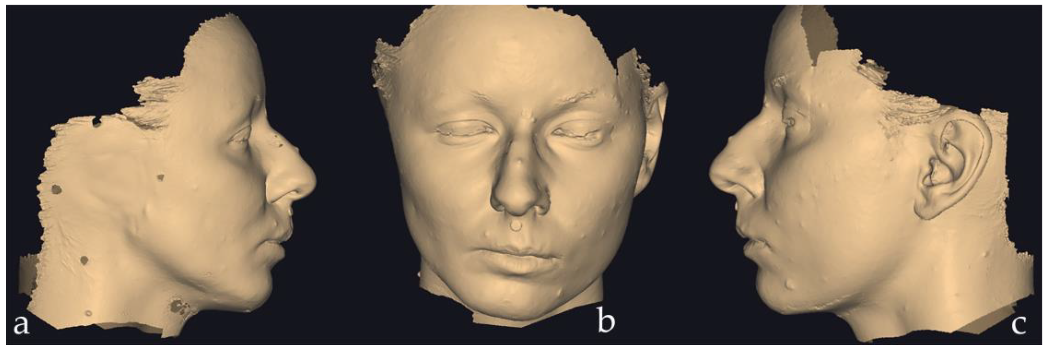
Figure 2.
Right lateral and frontal views of the epithesis design and its positioning on the patient’s face. The image is a screenshot from the Exocad HTML file, viewed using the freely available Exocad Webview platform.
Figure 2.
Right lateral and frontal views of the epithesis design and its positioning on the patient’s face. The image is a screenshot from the Exocad HTML file, viewed using the freely available Exocad Webview platform.
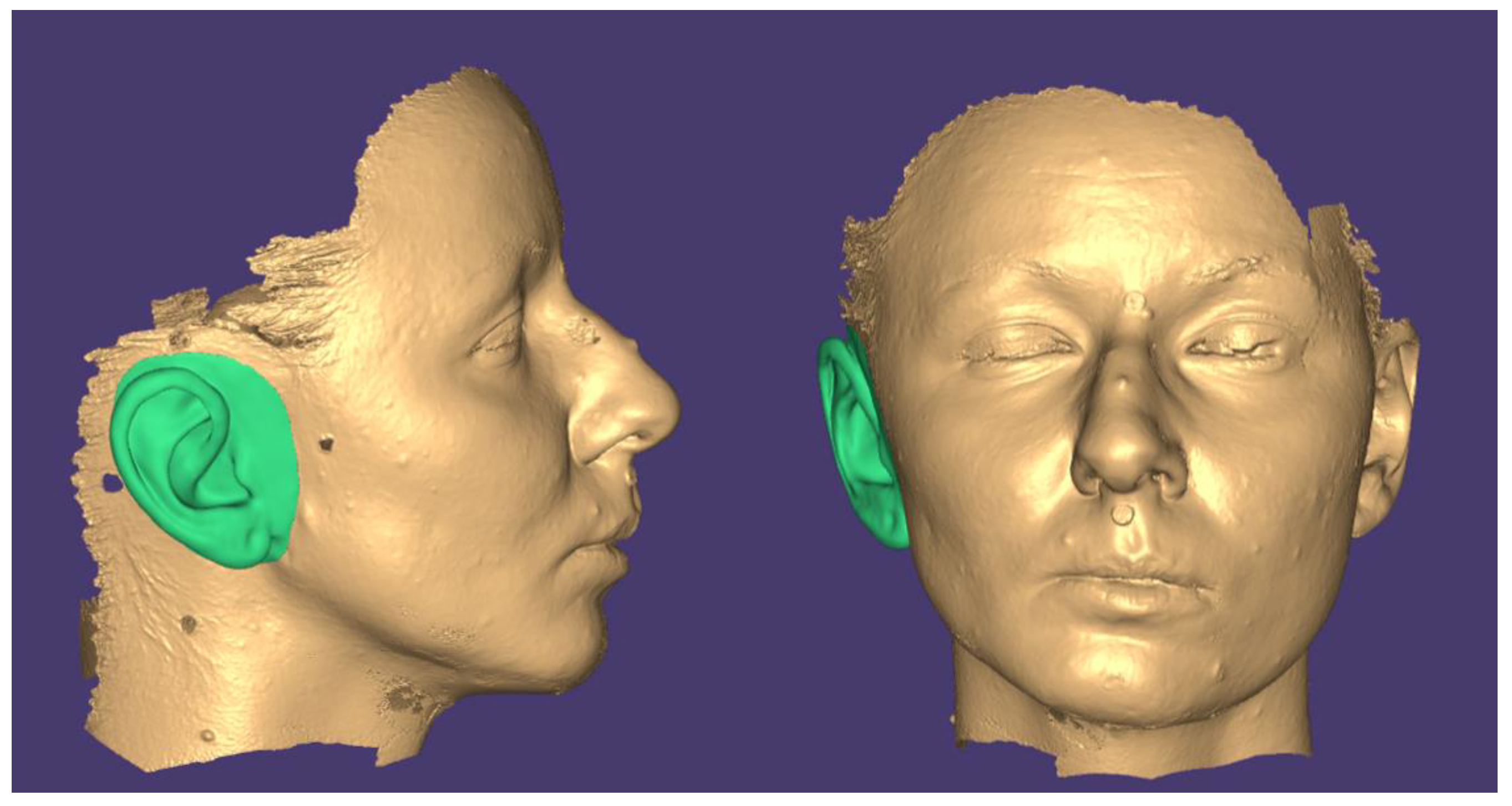
Figure 3.
The initial and final positions of the model in MeshLab: (a) front view, (b) right view, (c) top view and (d) isometric view.
Figure 3.
The initial and final positions of the model in MeshLab: (a) front view, (b) right view, (c) top view and (d) isometric view.
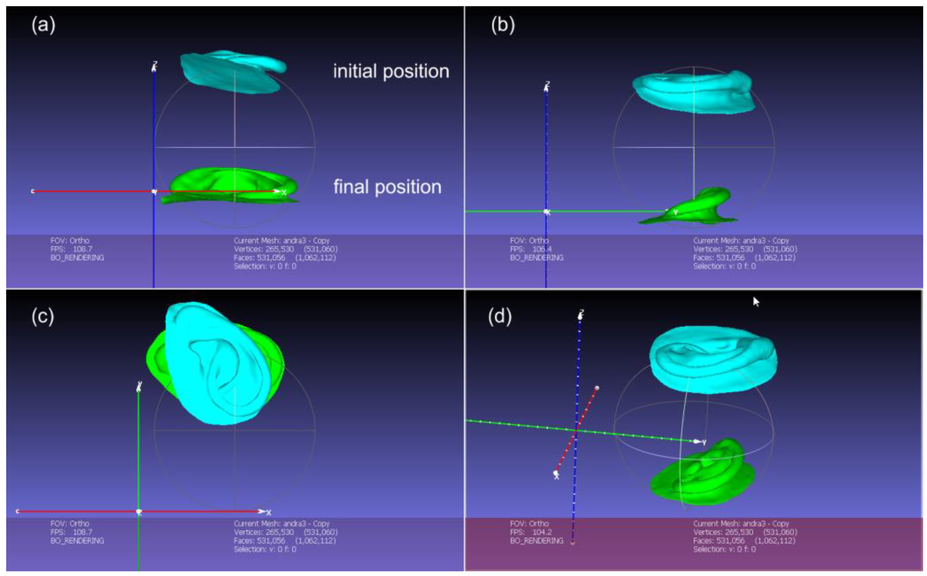
Figure 4.
The points cloud imported is represented in brown color, and the recognized surface in green color.
Figure 4.
The points cloud imported is represented in brown color, and the recognized surface in green color.
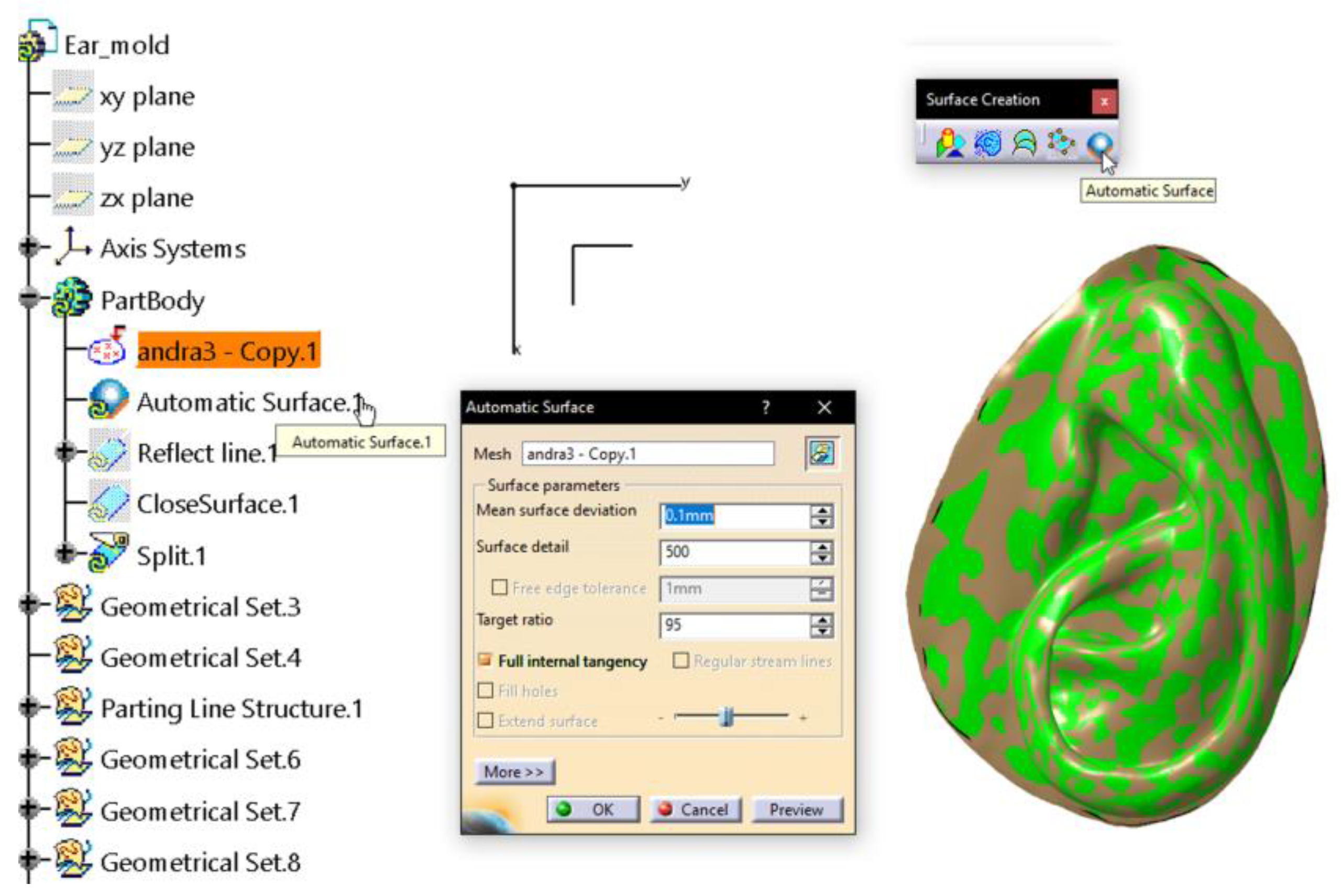
Figure 5.
The indicated purple curve is the parting line kept for the pulling direction along Z axis, provided by the vector [DX, DY, DZ] – [0,0,1]. The other curves are ditched.
Figure 5.
The indicated purple curve is the parting line kept for the pulling direction along Z axis, provided by the vector [DX, DY, DZ] – [0,0,1]. The other curves are ditched.
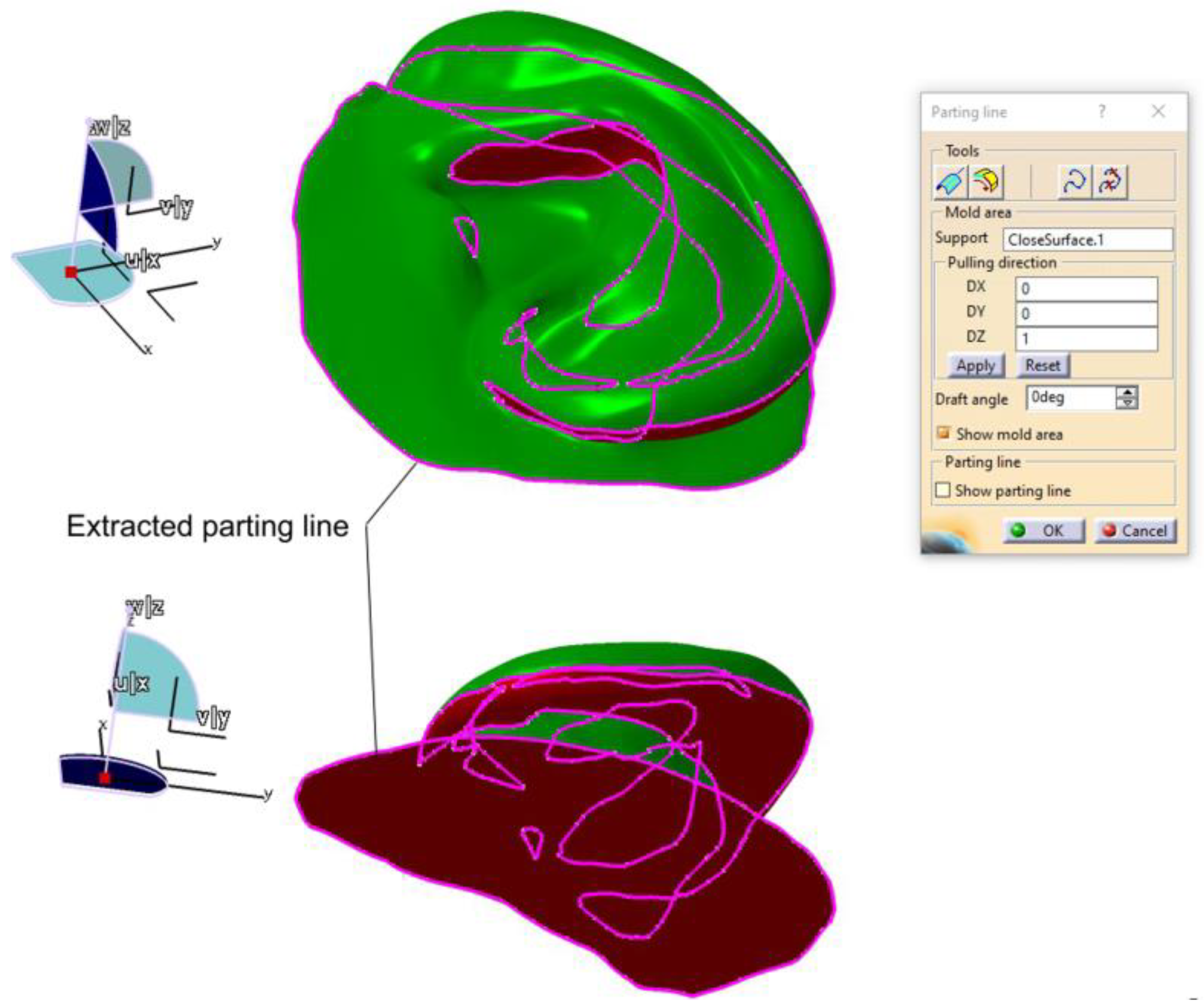
Figure 6.
The parting line computed along Y axis. Only the upper part of the parting line was kept and adjusted.
Figure 6.
The parting line computed along Y axis. Only the upper part of the parting line was kept and adjusted.
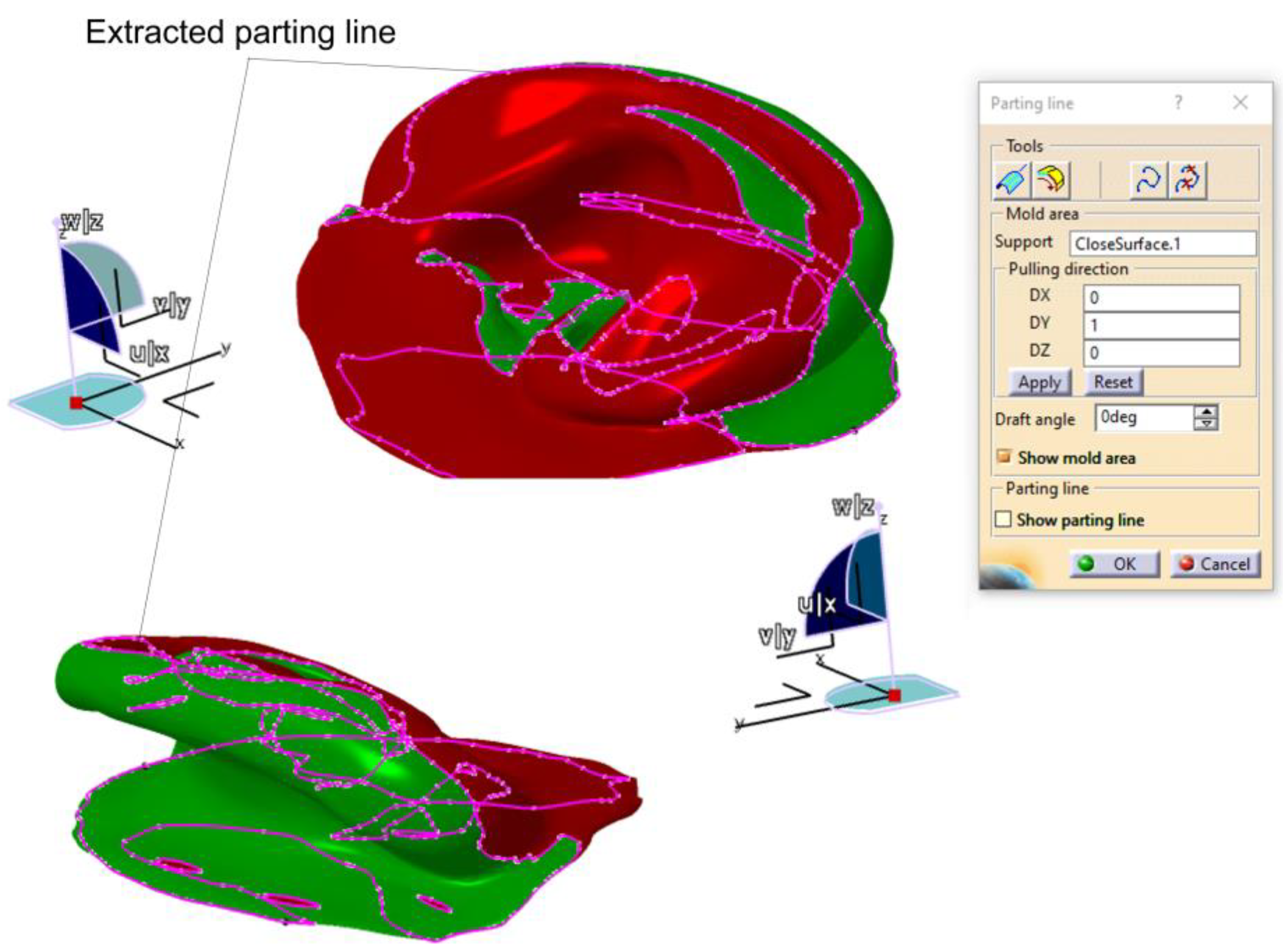
Figure 7.
The curves obtained as result of the automated process of defining the parting line along the Y axis and the curves kept for forming the actual parting line for the mold.
Figure 7.
The curves obtained as result of the automated process of defining the parting line along the Y axis and the curves kept for forming the actual parting line for the mold.
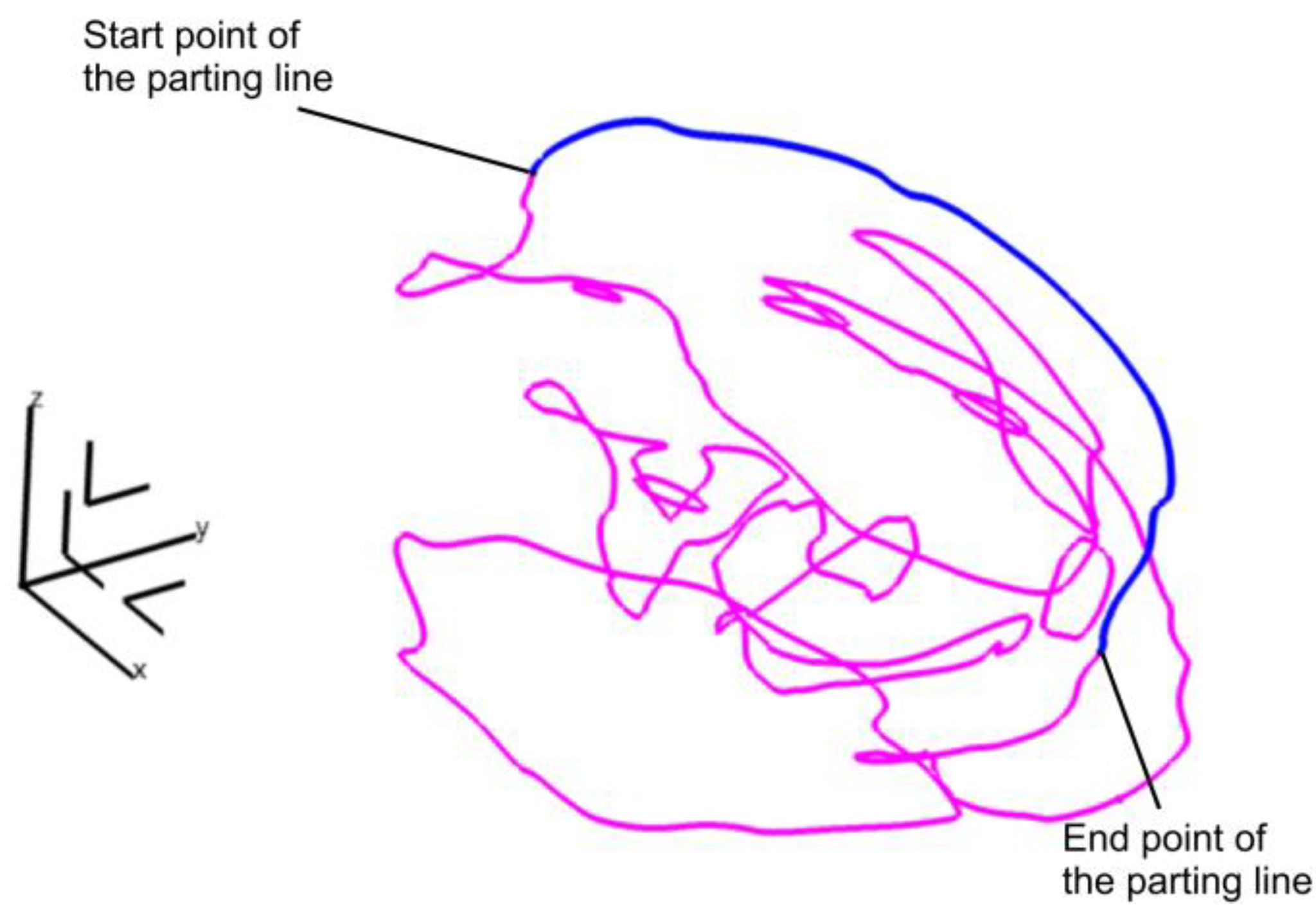
Figure 8.
The vertical surface is created and applied for splitting a solid body into two separate components.
Figure 8.
The vertical surface is created and applied for splitting a solid body into two separate components.
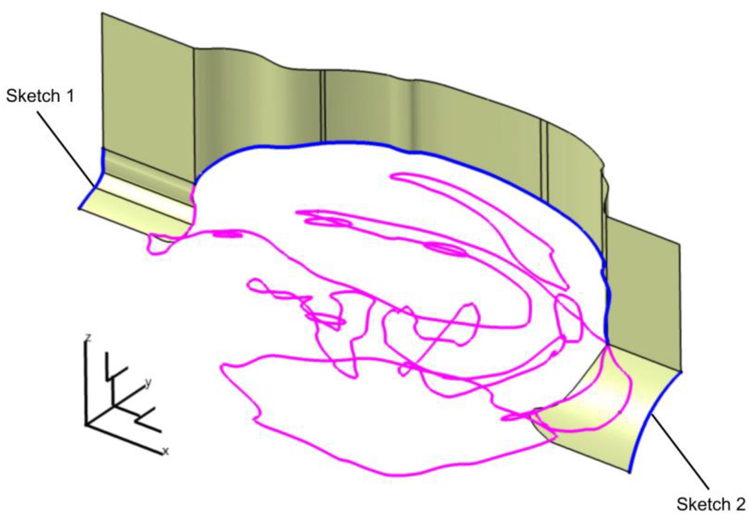
Figure 9.
The surfaces used to define the three-component mold.
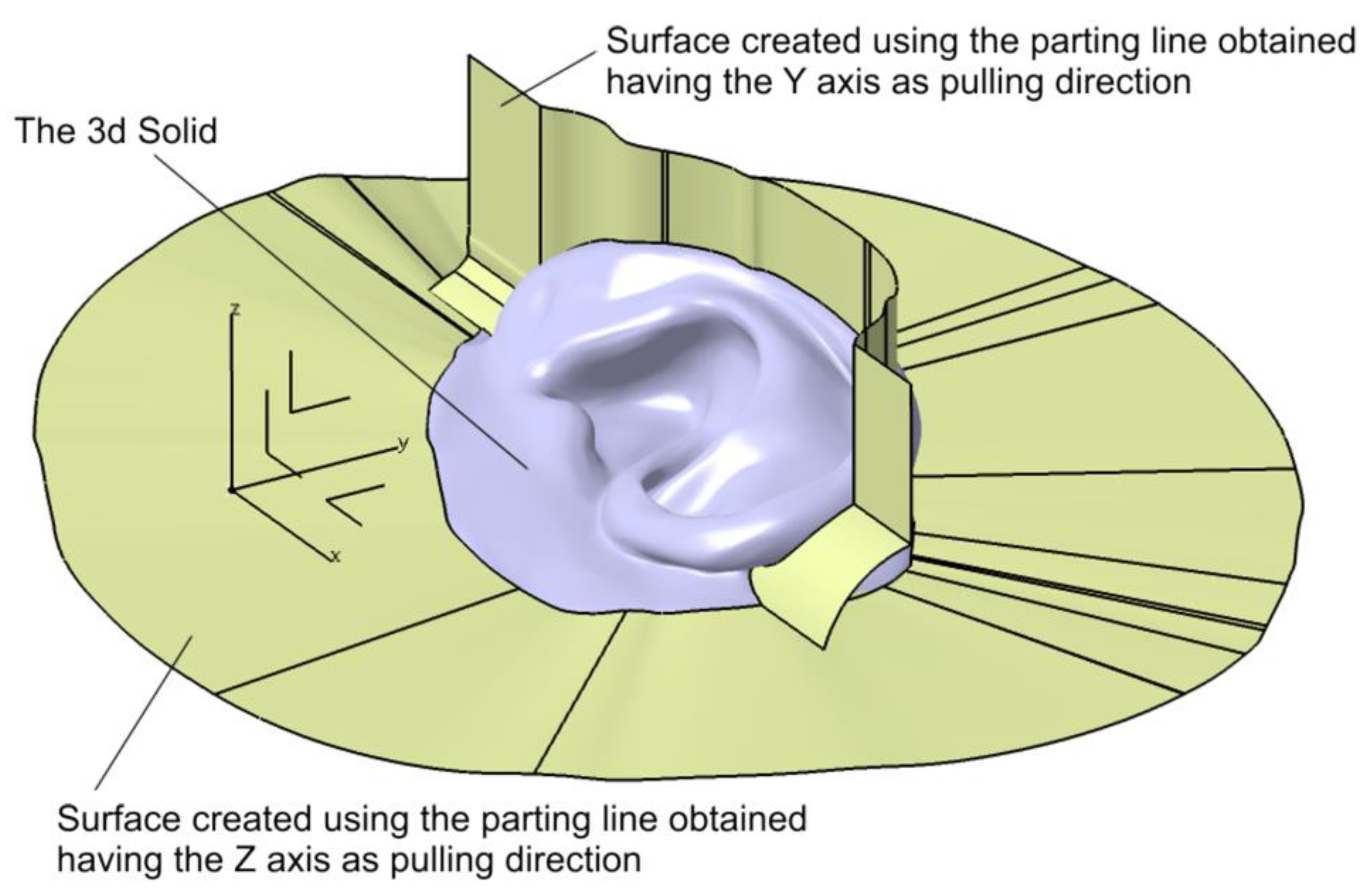
Figure 10.
The three – component mold assembly.
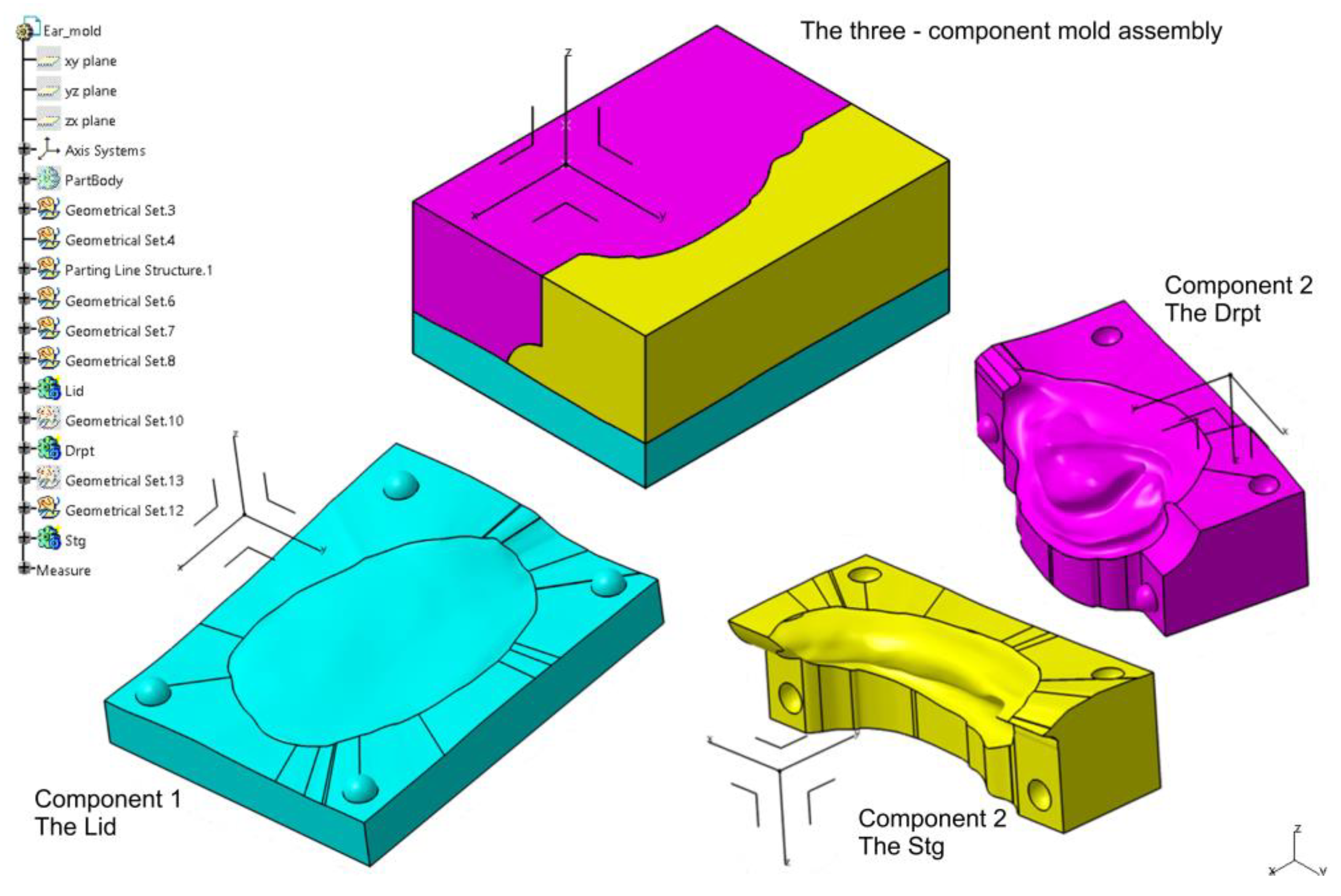
Figure 11.
The settings of the STL format of the Lid component of the mold.
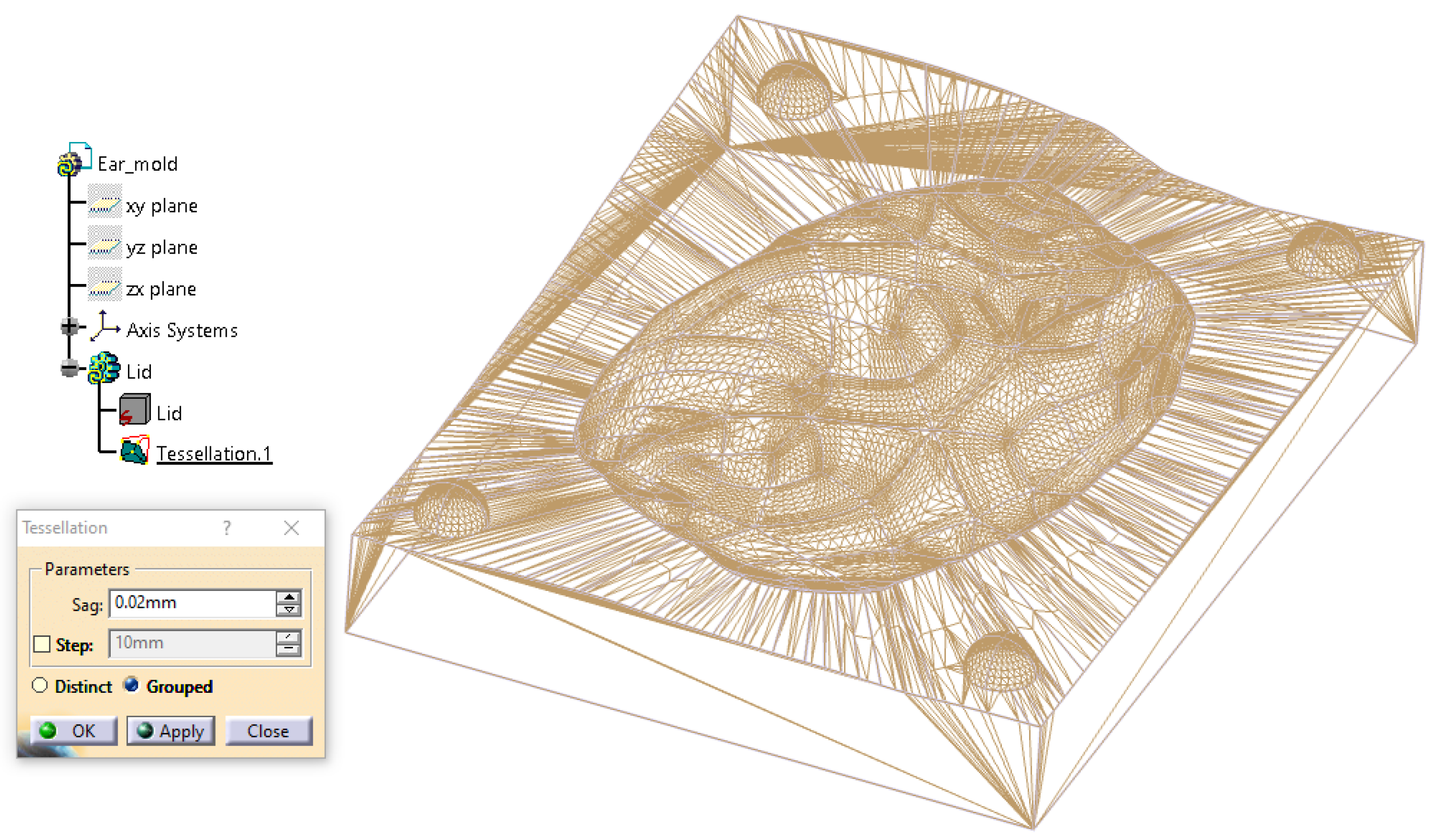
Figure 12.
Base mold (first segment) containing the posterior surface of the ear in contact with the defect site. This positioning is critical for the subsequent construction of the three-part mold, as the base defines the interface with the patient’s skin. Given the irregular anatomy of the prosthetic field, accurate placement in this component ensures proper alignment and facilitates safe and efficient demolding of the final silicone epithesis.
Figure 13.
Introduction of the second parallelepiped (Cube 2), rotated to match the auriculocephalic angle (25°) for posterior mold construction, simulating the natural ear projection.
Figure 13.
Introduction of the second parallelepiped (Cube 2), rotated to match the auriculocephalic angle (25°) for posterior mold construction, simulating the natural ear projection.
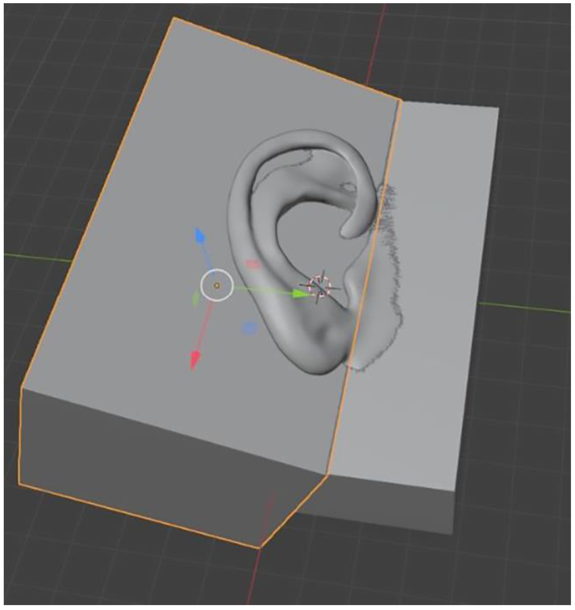
Figure 14.
Positioning of the third parallelepiped (Cube 3), aligned parallel to the base mold to form the anterior mold component.
Figure 14.
Positioning of the third parallelepiped (Cube 3), aligned parallel to the base mold to form the anterior mold component.
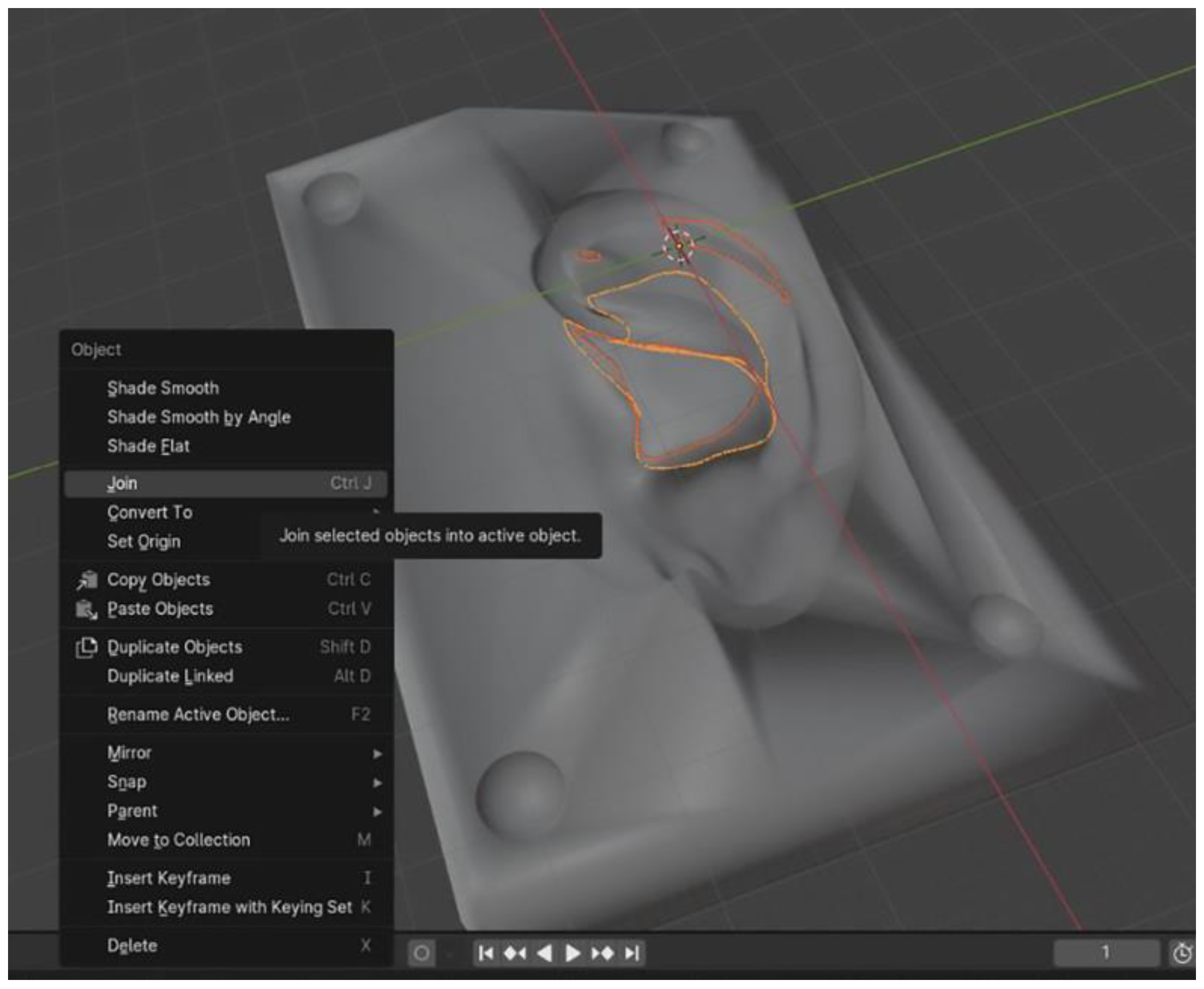
Figure 15.
Mold components positioned on the Elegoo Neptune 4 Plus build platform using the dedicated slicing software: (a) upper view and (b) lateral view. The three-part molds designed in Blender are placed on the right side, while those designed in CATIA V5R21 are positioned on the left side.
Figure 15.
Mold components positioned on the Elegoo Neptune 4 Plus build platform using the dedicated slicing software: (a) upper view and (b) lateral view. The three-part molds designed in Blender are placed on the right side, while those designed in CATIA V5R21 are positioned on the left side.
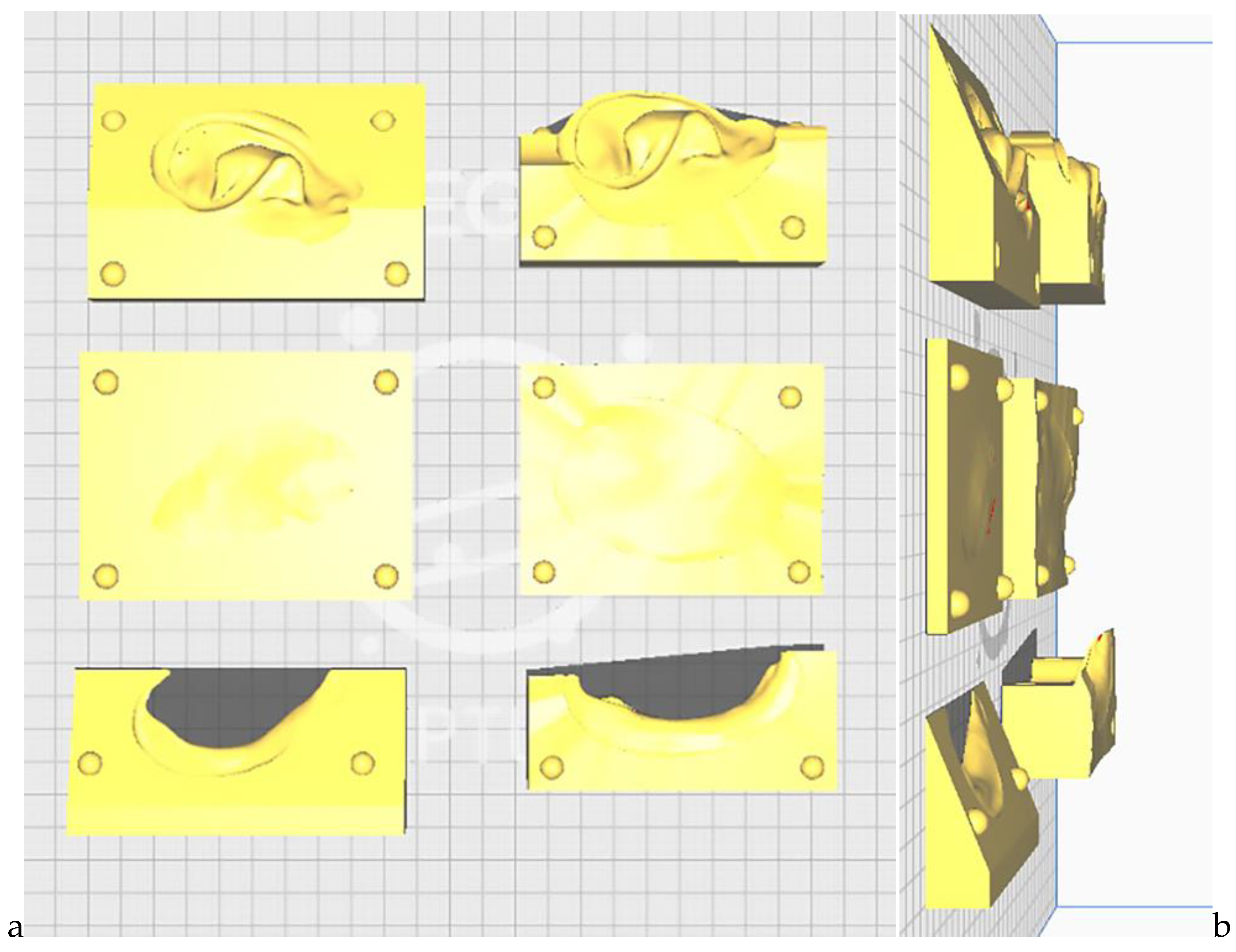
Figure 16.
The ten auricular epitheses fabricated using medical-grade HTV silicone: the upper row displays the five prostheses manufactured using the CATIA-designed molds, while the lower row shows those produced with the Blender-designed molds.
Figure 16.
The ten auricular epitheses fabricated using medical-grade HTV silicone: the upper row displays the five prostheses manufactured using the CATIA-designed molds, while the lower row shows those produced with the Blender-designed molds.
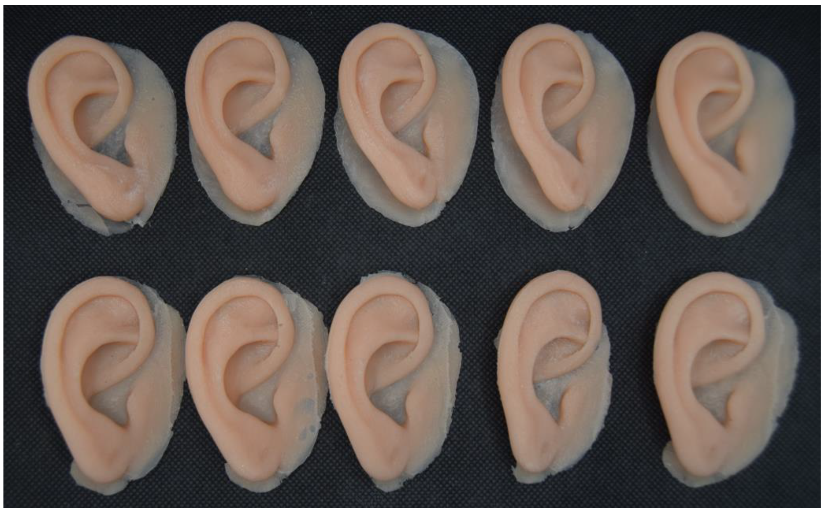
Figure 17.
Boxplot comparing Root Mean Square (RMS) deviation values, in mm, between epitheses fabricated using CATIA- and Blender-designed molds, highlighting the distribution, median, and variability within each group.
Figure 17.
Boxplot comparing Root Mean Square (RMS) deviation values, in mm, between epitheses fabricated using CATIA- and Blender-designed molds, highlighting the distribution, median, and variability within each group.
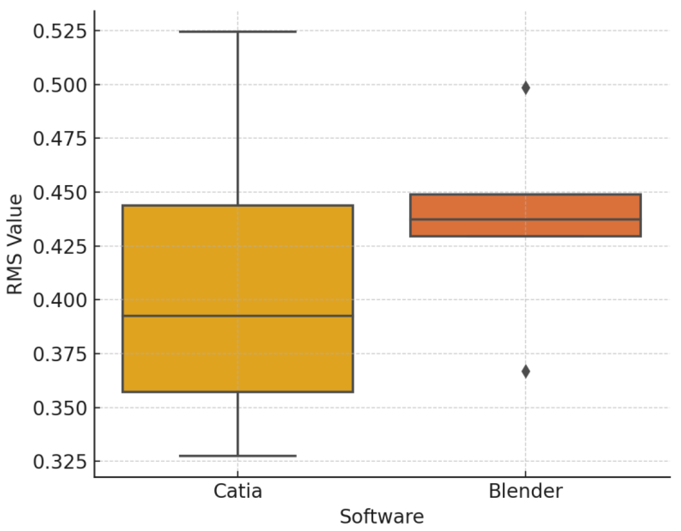
Figure 18.
Color map deviation analysis of the final silicone auricular prostheses fabricated using molds designed in (a) CATIA and (b) Blender. Over 90% of the surface area in both cases fell within ±0.3 mm of the reference STL geometry, indicating high surface trueness and dimensional fidelity.
Figure 18.
Color map deviation analysis of the final silicone auricular prostheses fabricated using molds designed in (a) CATIA and (b) Blender. Over 90% of the surface area in both cases fell within ±0.3 mm of the reference STL geometry, indicating high surface trueness and dimensional fidelity.
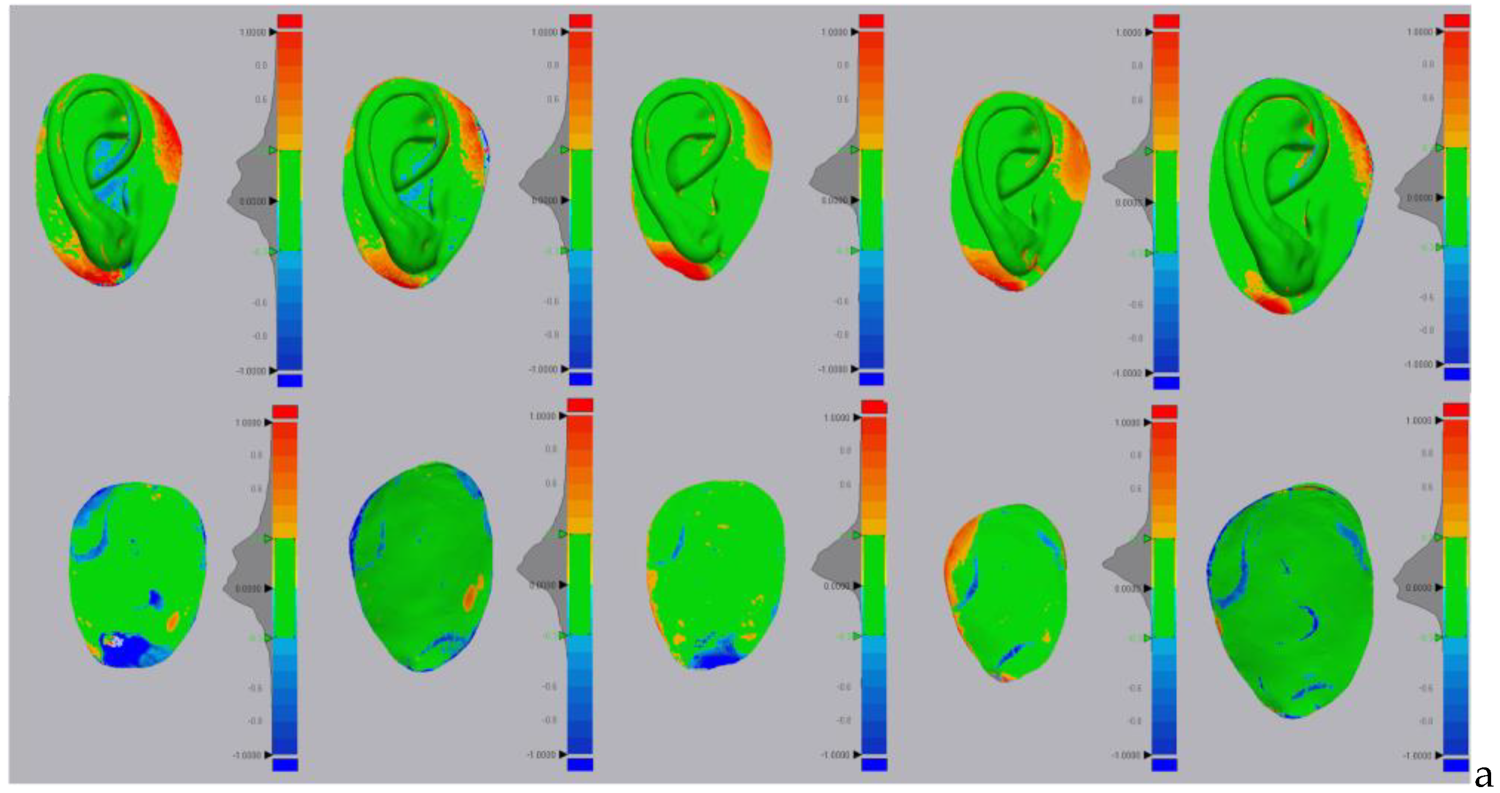
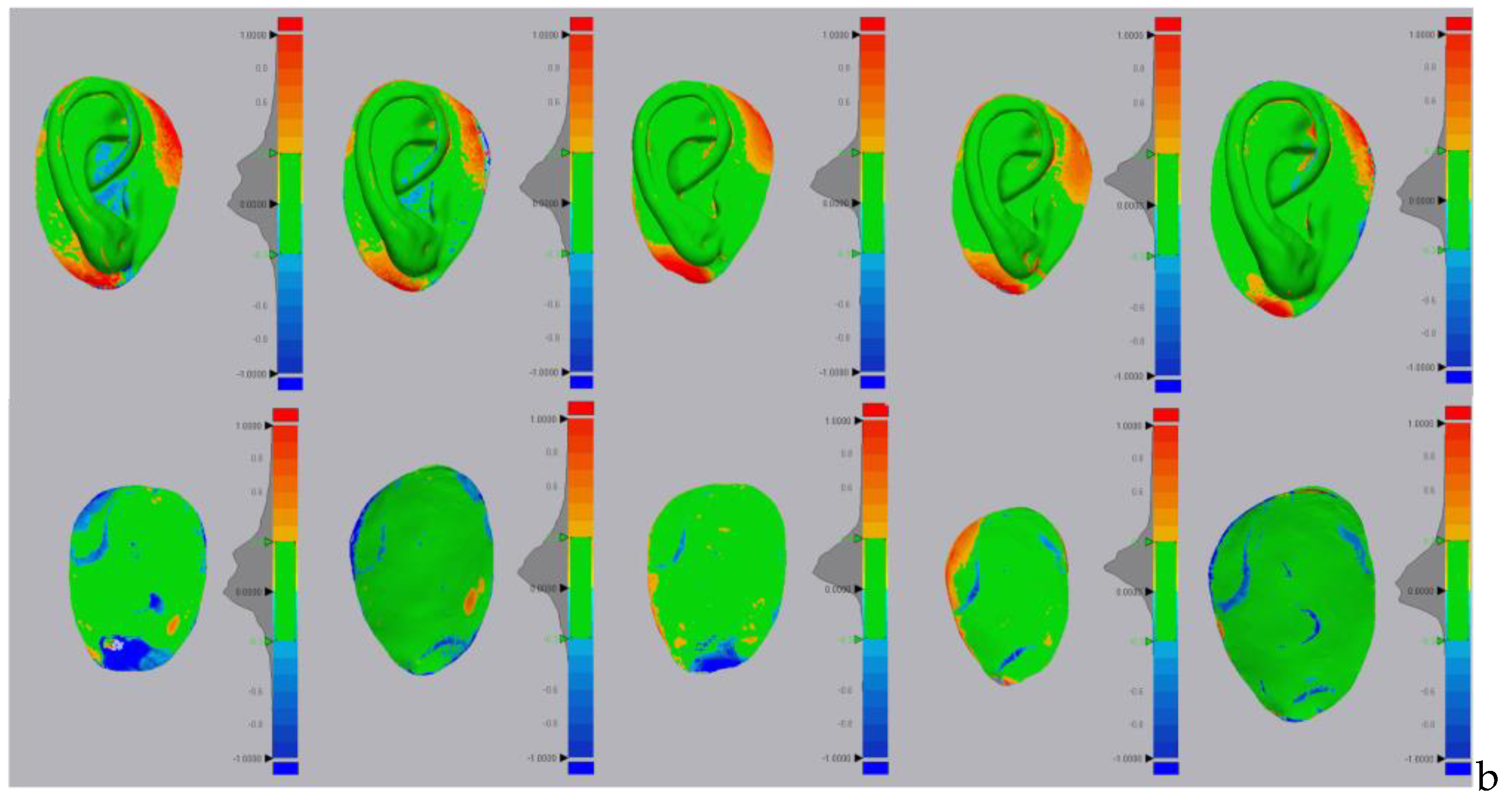
Figure 20.
Estimation of natural ear mass using CATIA software.
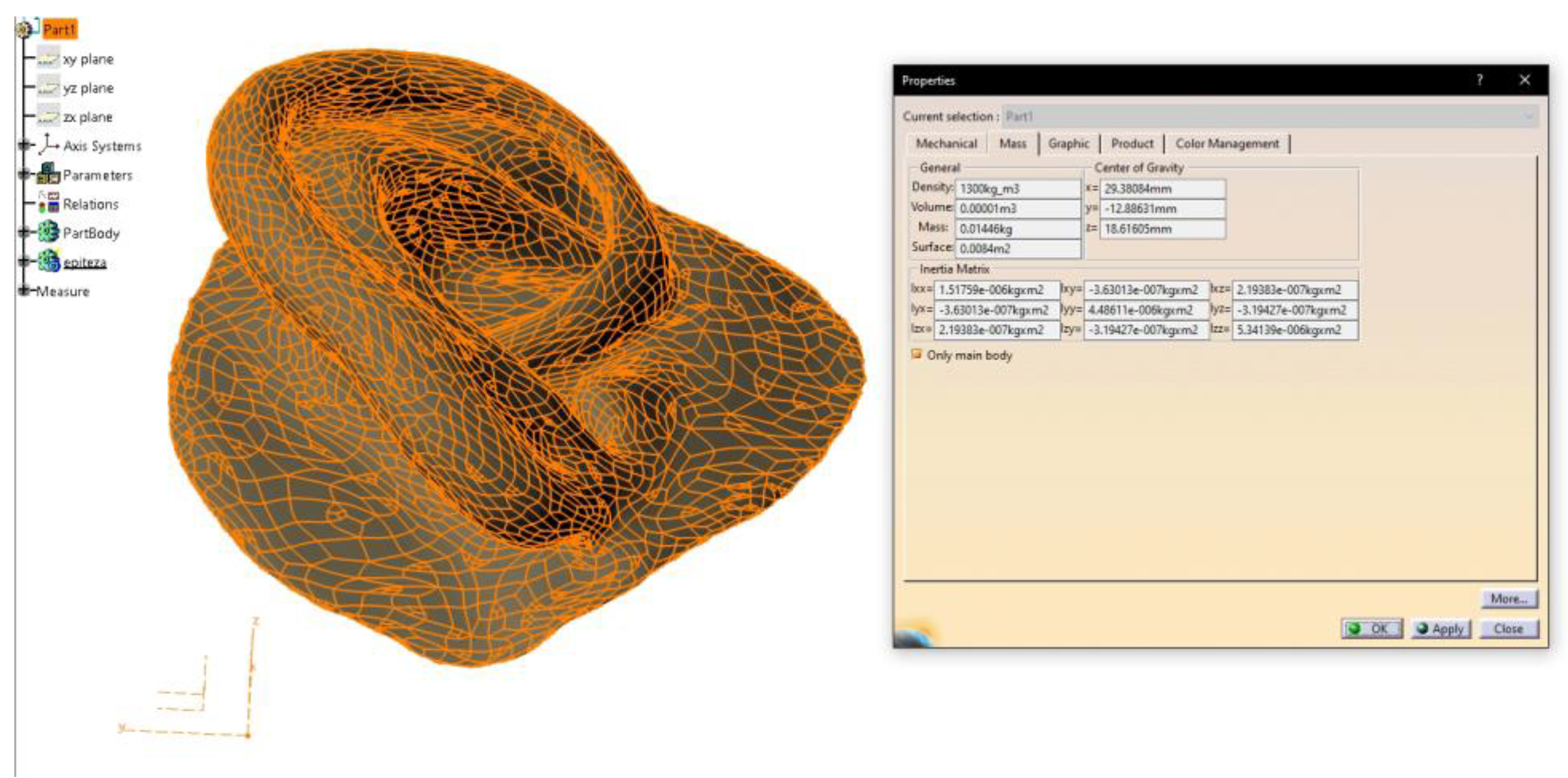
Figure 21.
Try-in of the patient’s preferred prosthesis (CATIA no. 4) prior to final delivery and extrinsic pigmentation. Views shown from left to right: right lateral view, posterior view, and left lateral view.
Figure 21.
Try-in of the patient’s preferred prosthesis (CATIA no. 4) prior to final delivery and extrinsic pigmentation. Views shown from left to right: right lateral view, posterior view, and left lateral view.
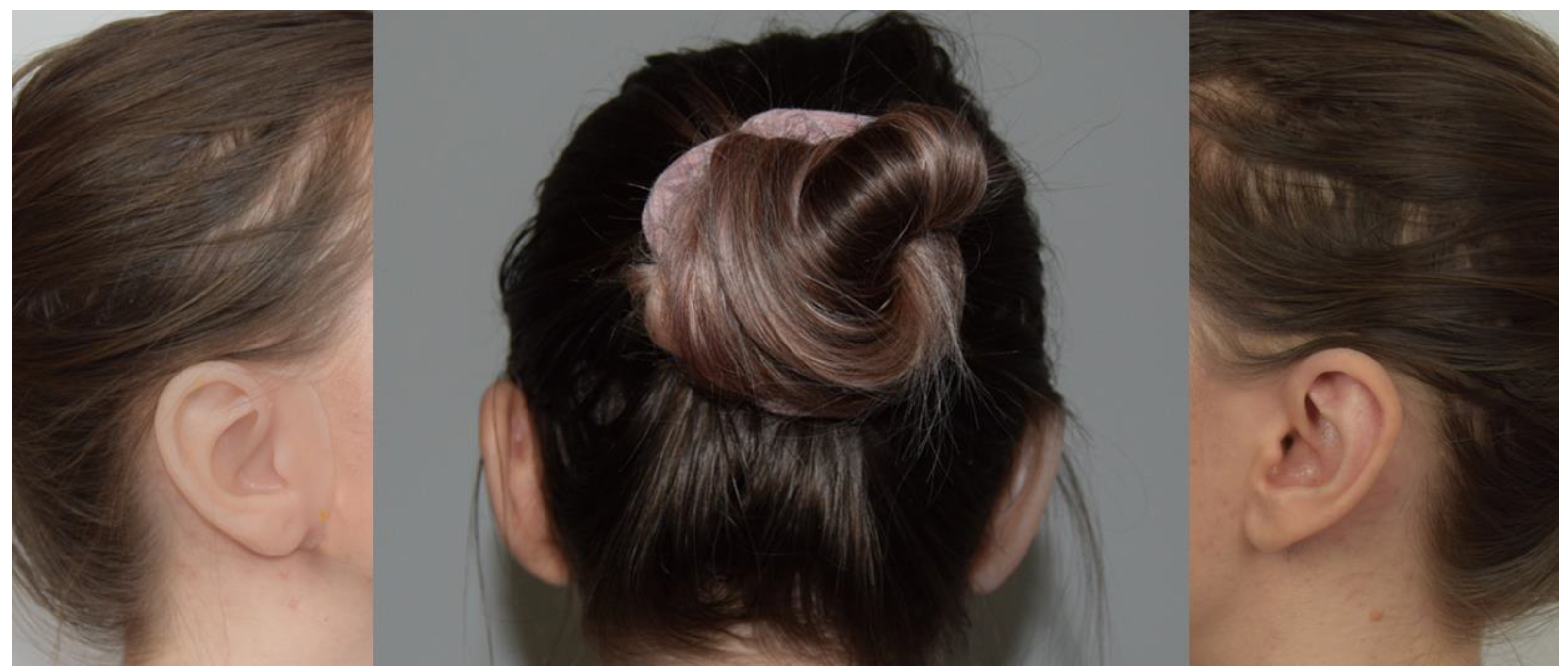

Table 1.
Comparative characteristics of the two software platforms used for auricular mold design (CATIA vs. Blender).
Table 1.
Comparative characteristics of the two software platforms used for auricular mold design (CATIA vs. Blender).
| Category | CATIA V5R21 (Proprietary CAD) | Blender (Open-Source) |
|---|---|---|
| Cost | High licensing fees | Free and open-source |
| User Interface | Engineering-oriented; steeper learning curve | Intuitive for artists/designers; community-supported |
| Design Precision | Very high, parametric and feature-based modeling making it suitable for any solid and surface design challenge | Moderate to high; mesh-based modeling |
| Workflow Structure | Modular (Generative Shape Design, Core & Cavity, etc.) | Non-parametric, flexible but more manual |
| Types of curves for 3D modeling | NURBS– default curves; but also supports Bézier Curves (less common) | Bézier Curves - default curve type; but also supports NURBS |
| Mold Alignment | Easier to define planes and alignment geometrically | Manual alignment using basic primitives and transforms |
| Export Compatibility | STL, STEP, IGES – excellent integration with industry tools | STL and OBJ – widely used, especially for 3D printing |
| Time to Final Mold | Slightly longer due to setup but repeatable and consistent | Faster for experienced users; requires manual steps |
| Learning Curve | Steep, especially for non-engineers | Moderate; easier for creative users |
| Mesh Handling | Native support for solids and surfaces | Native support for meshes and sculpting |
| Automation Potential | Higher for industrial workflows (via macros/scripts) | Moderate; can be scripted in Python but lacks built-in AI |
NURBS=Non-Uniform Rational B-Splines; STL=Stereolithography; STEP=Standard for the Exchange of Product model data; IGES=Initial Graphics Exchange Specification; OBJ=Object File.
Table 2.
Subjective evaluation results of the ten auricular prostheses performed by the independent prosthetic team and the patient.
Table 2.
Subjective evaluation results of the ten auricular prostheses performed by the independent prosthetic team and the patient.
| Mean (SD) | Catia | Blender |
|---|---|---|
| Patient evaluation | ||
| Esthetic | 9 (±0.71) | 6.6 (±0.55) |
| Comfort and Adaptation | 8.2 (±1.30) | 7.2 (±0.84) |
| Overall Preference | 8.6 (±0.89) | 6.6 (±0.55) |
| Overall Score | 8.6 (±0.40) | 6.8 (±0.35) |
| Experts Evaluation | ||
| Surface Texture | 8.73 (±0.76) | 7.89 (±0.18) |
| Anatomic Details | 9.27 (±0.68) | 7.67 (±0.00) |
| Ease of Handling | 9.67 (±0.00) | 7.47 (±0.18) |
| Overall Score | 9.22 (±0.47) | 7.67 (±0.20) |
Disclaimer/Publisher’s Note: The statements, opinions and data contained in all publications are solely those of the individual author(s) and contributor(s) and not of MDPI and/or the editor(s). MDPI and/or the editor(s) disclaim responsibility for any injury to people or property resulting from any ideas, methods, instructions or products referred to in the content. |
© 2025 by the authors. Licensee MDPI, Basel, Switzerland. This article is an open access article distributed under the terms and conditions of the Creative Commons Attribution (CC BY) license (http://creativecommons.org/licenses/by/4.0/).
Copyright: This open access article is published under a Creative Commons CC BY 4.0 license, which permit the free download, distribution, and reuse, provided that the author and preprint are cited in any reuse.


