
Submitted:
07 August 2025
Posted:
08 August 2025
You are already at the latest version
Abstract
The Building Information Modelling (BIM) methodology is currently the main support for the development of integrated and collaborative projects within the Construction industry, having been implemented in all sectors of activity and worldwide. The present study aims to disseminate the collaborative capabilities of BIM platforms on the development of multidisciplinary building projects, upon an integrated 3D BIM model, composed of architecture, structures, water network and electrical system disciplines. In addition, the study addresses the integration of BIM with Virtual Reality (VR) technology as a way of improving cooperation, understanding and accurate decision-making. The study describes the modelling processes of different disciplines, the analysis of conflicts between components, the establishment of the construction planning (4D BIM model) and the building cost estimation (5D BIM model). In order to cover in detail the various design components, the case study was limited to a specific area of a house, the sanitary room. This zone presents a sufficient complexity in the modelling process, in the identification and timing of construction steps associated with the necessary human resources, in the estimation of costs involved by discipline and construction component and in the application of VR software. The conflict analyses and the visual simulation of the construction planning were prepared using a BIM viewer. The VR and AR functionalities applied over the BIM model increases the potential of BIM in the construction sector, contributing to the achievement of a high level of collaboration and design correction supported in an immersive and interactive environment. The study allows to analyze the main advantages introduced in the construction industry and the barriers found in all the processes, concerning the creating a complete BIM model and its integration with VR and AR systems
Keywords:
BIM
; multidisciplinary BIM model
; Collaboration
; 4D model
; 5D model
; Virtual Reality
; Augmented Reality
; Integration BIM and VR/AR
1. Introduction
Following the government directives in order to increase the digital transformation in the Construction industry, the implementation of the Building Information Modelling (BIM) methodology has been introduced as a procedure supported by advanced technologies capable of speeding up the elaboration of integrated and collaborative projects, sustained and efficient, contributing to the achievement of accurate final products. In order to encourage BIM implementation in the construction industry, governments have been carried out oriented legislation to promote the increase of its adoption [1]. In addition, Virtual Reality (VR), a technology that allows users to interact in an immersive way with digital models, have been widely applied mainly in the context of building design, construction and maintenance [2]. The BIM methodology implementation has positively fomented the optimization of a higher productivity in the preparation of projects, in the quality control of construction and in the management and maintenance of buildings during the occupation stage [3].
The BIM digital model is created to characterize with precision in geometry and in physical properties the project under analysis. The virtual representation allows to mitigate eventual design errors, to reduce the duplication of information and to avoid the data inconsistency in transfer procedures between phases [4]. With the increase in the technology evolution underlying BIM, several software manufacturers have been adjusting their digital modelling products to include the BIM fundament, based on three-dimensional (3D) parametric modelling and, additionally, to develop specific scripts, plug-ins and extensions, aimed at the most diverse applications in the field of construction [5]. In the current state of the technology advances, the immersive VR stands out improvements in the construction sector, allowing users to create a simulated environment for interaction, transforming the traditional way the design, the plan, and the construction are elaborated [6].
BIM methodology has been adopted in different type of constructions, as recorded in numerous academic reports and in the description of practical building cases, demonstrating advantageous results [7,8]. However, it is noted that, there is some difficulty in introducing BIM in sectors such as structural design or energy simulation, due to a relevant level of inefficiency in the interoperability capacity that persists in model transfer processes between BIM-based systems [9]. The BIM methodology allows the creation of models with diverse volume and type of information, supporting the development of different tasks, and it is applied within the scope of a multidisciplinary project.
In the current study, a building case was considered [10]. The present work clear present the type of additional data that was necessary to obtain and inserted inside the initial 3D BIM model, created with the project information concerning the representation of the distinct disciplines [11]:
- The target of the modelling process, described in detail in the present study, allows professionals to understand the main advantages of BIM adoption, concerning the level of collaboration and the integration capacity between all disciplines. In the context of the application of BIM over the selected study case, the elaboration of the architectural project was first conceived, followed by the modelling of the structural solution and of the water and electricity networks. These components composes the 3D BIM model (item 4);
- In addition, the study put in evidence, the facility of obtaining the quantification of the material applied in distinct project components. This is a relevant task easily developed over the 3D model composed of all the disciplines, named the 4D BIM model. Following this perspective, the study demonstrates how the aspects of collaboration and budgeting, are tasks that can be elaborated in an agile, correct and complete, using a multidisciplinary 3D BIM model with a high level of detail and additional information incorporated (item 5);
- In the establishment of the construction planning activity, concerning the generation of the 5D BIM model, it was necessary to increase the information of the initial 3D BIM model. Namely, in relation to the identification of construction tasks and the calculation of the respective execution period. The association of data related to unit costs constitutes a complementary information that was added to the parametric objects used on the creation of the 3D model. As so, the required information for this activity was added, and this feature should be understood as a benefit and not a limitation [12]. The database of a complete 3D model, composed of tasks and unity costs, is insufficient to obtain correct 4D and 5D models (item 6).
- The present research also explores the association and integration of BIM with VR technology illustrating the improvement of the BIM methodology when incremented with VR functionalities. Two VR/AR software were used to support and review the design, improving stakeholder engagement by giving design teams the ability to present a realistic representation of a design in a early stage of its development (item 7).
2. Materials and Methods
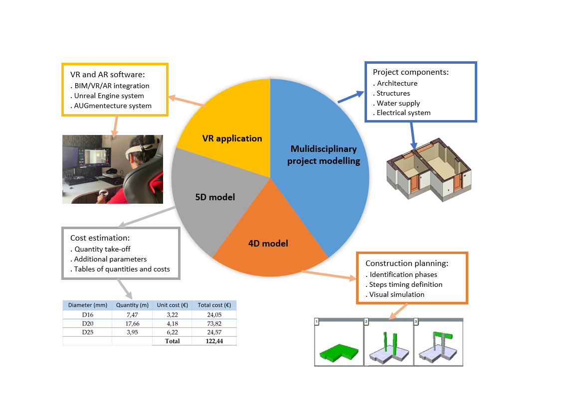
The present work aims to contribute to improve the dissemination of the potential of BIM concerning the integration and collaboration with the use of BIM and VR/AR software on the execution of tasks normally required in the preparation of a complete project (Figure 1):
- Collaboration between professionals from different disciplines can be strongly boosted with the generation of all components of the 3D BIM model, related to each field, and eventually developed by distinct professionals or located in remote locations, constituting a fundamental characteristic of BIM, but which in current practice is not yet sufficiently applied [13]. The 3D BIM model generated within the present study is composed of architecture, structures, water network and electrical system disciplines;
- In the context of the activity inherent to the industry, there is still a lack of some dissemination aimed at the potential of BIM in the construction planning process, with the possibility of simulating the animated visualization of the planed work, allowing users to compare the planned construction with the real one on site [14]. The design elaborated in this context is normally named the 4D BIM model;
- In addition, there is still some resistance to the understanding that a complete 3D BIM model, in terms of information associated with each project component, can constitute an appropriate database for the development of detailed budgets by discipline, component or construction zone [15]. This activity, known as the 5D BIM model, requires the elaboration of the quantity take-off activity and the insertion of the unity cost as new parameter of the objects applied in the model;
- The use of VR and AR systems in construction has been applied mainly in the design visualization and collaboration, but the development of more advanced technologies and the falling costs of VR/AR hardware have made it more accessible and widely adopted by the construction industry [16]. There are many benefits in using virtual reality in construction, including the ability to streamline project planning and coordination, facilitate project visualization, enhancing asset management and improving quality control. The present study links BIM and VR/AR.
3. Concepts and Technological Evolution of BIM and VR
3.1. Building Information Modeling (BIM)
Building Information Modelling (BIM) is a methodology supported by advanced technology software that allows the development of virtual digital models composed of parametric objects associated with a height level of comprehensive information about the materials and related physical properties. Using a BIM software, a model is created for each project in progress, presenting a great geometric detail and behavior precision, supporting the elaboration of different phases concerning the design evolution, the construction work and, after occupation, the management and maintenance activities [17].
Erik Jan Van Nederveen and Frits Tolman mentioned the first reference to the term BIM in 1992 [18]. However, since the 1960s, the base concept, that is modelling with embedded information, was referred to by the term Building Modelling. In 1975, Eastman [19] first mentioned the fundaments of the BIM methodology, referring to a hierarchical system of building components in the composition of a digital model, using the designation as Building Product Model (BPM). The author described a system that allows to create elements associated with shape, location, and property information.
As referred by Succar [6], the designation Building Information Modelling (BIM) was adopted, is a set of interacting policies, processes and technologies generating a methodology to manage the essential building design and project data in digital format throughout the building's life-cycle. Currently, BIM has been adopted by several countries. The elaboration of a building project, involving all disciplines and the required associated task, using the available BIM software, is provided in the form of a digital parametric model, containing the geometric details necessary for its realistic visualization, but it also incorporates several types of mechanical properties, such as density or modulus of elasticity of the applied materials. The BIM model offers a complete, updated, and accessible database, allowing data sharing between partners and phases, encompassing all stages of the life cycle of a building [20].
The final design, following the required specifications and adjustments according to the endorsed modifications in a collaborative and integrated way, allows to obtain a high-quality product. The enhanced capability, evident in teamwork, coordination, and collaboration, leads to improve performance of professionals and reduced costs associated with the project design, providing benefits to all experts involved. Currently, the resistance to its implementation has been changing, towards moderate acceptance by all professionals in the various areas covered by the industry. Companies have been recognizing that this transition is inevitable and its implementation in work practices should be understood as a mandatory requirement. In all areas of the construction industry, owners, designers, builders, and managers have been reporting the benefits of adopting the BIM methodology in their specific activities. This has contributed to the rapid and growing acceptance of BIM, leading government entities to establish guides and deadlines for mandatory implementation in public buildings [21]. Despite the relative benefits of implementing BIM in industry, its adoption in enterprises and project offices has been imposing significant organizational challenges related to internal cultural adaptation regarding ways of working, data transfer processes, and communication with partners [22].
Despite the constant effort in research, carried out in academic and business environments, the persistent limitation of interoperability in some of the tasks that require a model transfer process, in the pursuit of the development of different stages of the project, the technology market still does not provide a completely effective solution, negatively affecting its implementation [23]. This makes interoperability the main practical barrier to successful BIM adoption in the industry [24].
3.2. Virtual Reality
Virtual Reality (VR) is a technology with the ability to represent environments created by computers in order to provide users with an immersive virtual simulation [25]. VR allows the user to experience situations in an interactive virtual 3D background.
The first time the idea of immersing oneself in a virtual world, similar to the real world, and interacting with it, was mentioned by Ivan Sutherland, in 1965 [26]. In 1957, Morton Heilig created the first multi-sensory simulator, named The Sensorama Machine (Figure 2 a). This simulator was created with the purpose of allowing the user to experience sound, smell, wind and vibrations while watching a movie.
Thomas Furness produced the flight simulator, the Vehicular Collision Avoidance Support System (VCASS), in 1982. It presents technological advances, enabling a helmet to display and provide the necessary information for learning simulated flight training. The first VR device commercially available was the DataGlove, in 1985, and after the head-mounted display (HMD) (Figure 2 b). In 1965, Sutherland introduced the first helmet with integrated glasses, the Sword of Damocles, a device that allows the use to monitor the movements made by the head (Figure 2 c).
VR technology can make a significant impact on how construction project stakeholders can perceive and successfully complete their projects. For the construction sector, the main advantages are based on the use of VR as an aid tool in construction planning, in the more efficient layout of the construction site and in the verification of incompatibilities of execution on site. In addition, the development of new construction can be studied and trained within VR environments, improving the skills of the workers. In the search for solving feasibility problems, it is possible, in the design phase, to analyze the alternative solutions that best suit its uniqueness.
VR technology can be applied in addition to the BIM concept. The BIM model, composed with all the details defined for all specialties, can be exported to a VR system, allowing the user to experience the inherent advantages of immersion and interaction with the virtual space. The required export process of the BIM model to a VR software has been evaluated, in order to identify the degree of interoperability between the systems. Recently, more integrated systems have been developed, promoting better interoperability capacity and, therefore, improving the efficiency of BIM/VR processes [27].
VR technology has the potential to enhance the efficiency and effectiveness of all stages of a project, from initial conceptual design through detailed design, planning and preparation, to construction completion. The BIM model is an adequate basis for study and cooperation between partners, but the addition of VR leads to an increase in the ability to realistically visualize and understand the project. With the immersion of the user in the model space, the level of communication and understanding between the various stakeholders is thus increased [5]. The simulation of the construction evolution in a VR environment allows the analysis of the different approaches to the construction design and planning, which can lead to a reduction in costs and construction time, as well as saving in eventual errors and to verify that the planned construction methods are effectively viable. In the present study, in order to support the illustration of the applicability of BIM/VR two experience of VR/AR were applied over the 3D BIM model generated for the selected building case [11].
4. 3D BIM Model
The selected case study used to develop the multi-project in a BIM environment, is just a part of a single-family house, concerning the sanitary rooms [11]. Focusing only on the two sanitary facilities highlighted in the project provided, it was possible to definite, in a complete way, the model of the various disciplines and carry out its analysis of compliance with the possibility of overlapping models (architecture, structures and water and electricity networks). The complete and detailed BIM model allows the detection of physical conflicts between the various disciplines.
For the accommodation of the sanitary service facilities, it was necessary to first create the architectural component of the BIM model, after the structural solution, followed by the water and electrical supply systems. The modeler BIM system used was Revit (Autodesk) [28]. To support the modelling process, the design office provided the necessary CAD drawings.
4.1. Architectural Component
The generation of a BIM model begins with the selection of the template correspondent to the discipline to be created. The next steps correspond to the establishment of the work units, the identification of each floors considered in the model, and the alignments defined in the plan necessary for the insertion of vertical elements. The two toilets rooms are contiguous and are located on the first floor of the house. Following the information contained in the CAD drawings of the architectural project, a grid of alignments were considered as well the levels related to the 1st floor and roof with the values of elevation of 12.65m and 15.85m, respectively.
The generation of the architectural component initializes with the modelling of the surrounding walls of the area under study, having been created new parametric objects, representative of the exterior and interior walls and also of a short wall bordering the terrace roof (Figure 3 a):
- The exterior wall was defined with the required layers composed of different material and thickness (porcelain stoneware tile, mortar, stucco, 11cm brick, extruded polystyrene (XPS), air box, 15cm brick and plaster);
- Three type of interior walls were considered: 15cm thick (11cm brick panel covered with stoneware tile); 25cm thick, shared by the toilets and other divisions (7cm and 11cm brick panels with plaster coatings and ceramic elements); 21cm thick, shared by the two toilets (double brick panel of 11cm and 7cm, with rock wool insulation).
The doors and windows were placed according to the CAD design supplied. The Revit material library contains several type of materials, but for the model, new materials were created, through the Create New Material option, included in the material selection interface, for the porcelain stoneware and the XPS insulation layer. In addition, distinct information was inserted as values of some of the parameters that composes the new wall objects: the supplier, the selected model, the manufacturer's website and the material application guide (Figure 4 a).
Through the Graphics section of the parametric object it is possible to select the graphic patterns:
The terrace roof was initially modeled as a slab of constant thickness. After its upper surface was adjusted to the required flow slop (Modify Sub Elements option) (Figure 5).
4.2. Structural Component
The structural solution is composed of columns, beams and slabs. Within the columns family available in Revit it was selected the rectangular concrete cross-section option. Two columns were defined: 0.20x0.20m2 and 0.20x0.40m2 cross-section columns. In addition, a beam of rectangular cross-section was created with the dimensions 0.20x0.45m2. From the architectural component, two reinforced concrete slabs were retrieved (Figure 6).
The structural elements correspond only to the sanitary facilities area, necessary to later include the water and electrical network systems, and avoiding conflicts. In order to be able to automatically obtain from the model a correct quantification of the materials, the volume of the structural elements was deducted from the volume of the walls. In the Modify menu, when applied the Join option over the model, this functionality removes the wall volume equivalent to the structural element and merges the two elements in such a way that the two geometries are no longer accounted for in the same space. Thus, it is important at this stage to overlap the two disciplines and to proceed with the analysis of conflicts and inaccuracies in the BIM model composed of both disciplines.
4.3. Water Supply System
The water supply project was modelled based on the parametric objects selected from the library provided in Revit. The required sanitary equipment, such as bathtubs, showers, washbasins, taps, bidets and toilets, were easily accessed through the BimObject, from the website provided by Autodesk (Figure 7 a). The water supply network establishes the connection between the public network and the distinct equipment located in the sanitary rooms. Using again the BimObject website, the piping elements were imported in the material referred in the project, formed of multilayer. In the model, when selecting a device that requires a water supply, such as a basin tap, two blue and red icons are displayed, corresponding to cold and hot water, respectively. After selecting one of the icons, the chosen pipe network is generated, and it is necessary to indicate the characteristics of the pipe section such as the required diameter and the respective elevation, information retrieved from the CAD drawings (Figure 7 b).
The modelling of the water networks verified the recommendations and good practices expressed in the applicable national guide [29]:
- For the cold water, the interior plumbing was considered to have a coating greater than 2cm, and is not embedded either inside the structural elements or the floor slabs with a structural function. For the modelling of the hot water network, it was developed in parallel to the cold water pipes in a higher plane at a distance of not less than 5cm (Figure 8 a).
- The modelling of the piping network for water drainage the process is very similar to the design of the model for water distribution networks. As indicated in the project provided, the material applied corresponds to polyvinyl chloride (PVC). This material was created in Revit as a new material, and the properly established graphical appearance and associated properties were queried from the related product catalog (Figure 8 b).
Once the modelling process of the water networks is completed, the interference between disciplines was analyzed. Physical collisions between pipes and fittings, devices, walls and columns were detected and subsequently adjusted. In its resolution, some sections of pipe were moved and some pass fittings were also created, such as crossing unions, in order to avoid the intersection between pipes.
4.4. Electric System
For the modelling of the electricity project, parametric objects representing double switches, light points and single-phase earthed sockets were used. Through the Space option, the two sanitary facilities were designated as "WC 1", the largest space, and "WC 2 " the space of the smallest area. In the modeling of the project, the socket devices were selected, through the Power option, followed by the Edit Circuit icon, and were added to the circuit. Then, the required light points and switches on the walls in each sanitary installation were placed on the ceiling of the first floor. The electrical circuit has two components, one related to energy (Power) and the other related to switches (Switch). For the circuit of switches, only the lighting corresponding to each sanitary installation was selected and connected to the corresponding switch. The power circuit was connected to an electrical panel.
Considering that the model created refers to the two sanitary installations, the electrical devices are not connected to the panel, but only to each other. Finally, the network of electrical wires was laid. In this model, the automatic connection option has been used. However, some adjustments to the tracing of the wires were considered, and lines were removed and others added according to the project (Figure 9).
5. 4D BIM Model
Over the generated 3D BIM model, composed with the projects of the four considered disciplines, the correspondent 4D and 5D models were also generated.
Part of the information inserted in the 3D BIM model supports the establishment of the construction planning of the building component in analyses, enabling the visual simulation of the process and the monitoring of the real building work. For the generation of the 4D model (3D model + time factor), the BIM model was transferred to a BIM viewer, the Navisworks (AutoDesk) software, compatible with Revit. Navisworks allows the application of various type of activations over the created model, namely, the clash detection analyses or the photorealism representation.
5.1. Identification of Activities and Duration
In order to define a 4D BIM model, the periods to the construction tasks must be calculated and associated with the respective elements or set of elements of the 3D model. Fundamentally, a Gantt chart is a bar map where each line represents the start and finish dates of every construction task. A Gant chart can be generated using a planning construction software such as MS Project (Microsoft), Primavera (Oracle) or a simple Excel software (Microsoft). In the present study, it was selected the Excel, allowing to identify the construction stages and to calculate the respective execution time. The Revit model was then first exported to the Navisworks software. After the required Gantt map is correctly defining it was also transferred to the same software.
Within the scope of the present academic study, the development of a multidisciplinary project was conceived in a perspective of disseminating the understanding and knowing, concerning the required modes of action. The planning component was established based on the identification of tasks, chronology and sequence, listed in an Excel file, and forming a Gantt map. The columns of the table refer to the order of activities, designation, beginning and end time of each activity. The duration of each activity was stipulated based on tables of labor man-hour rate related to each type of construction work. The tasks that were considered initialize with the structural components (slabs; columns and beams), followed by the evolving architectural elements (walls and roof), the water and electricity networks, the architectural complements (windows, doors and sanitary equipment) and finalizing with the lighting devices. For the execution of all works, it were considered two men:
- Concreting the floor slab of the 1st floor corresponds to a man-hour rate of 1.25/m3, a rate that is then multiplied by the concrete volume of 2.6m3, a value obtained through the capacities of Revit. The result value is divided by the two workers, having been obtained the 1.60h (Table 1);
- The reinforcements work requires the cutting, the folding, the framing and the placement of arms in the place, inside the formwork of each structural element. The productivity associated with bars of diameter 10mm and 12 mm is distinct. The man-hour rate for the reinforcement is quantified per 10kg of steel and as so it was necessary to estimate the weight of all the reinforcements. It was obtained a total weight of 212.5kg and 118.8kg for the bars of diameter 10mm and 12mm, respectively, corresponding to 3.35h and 1.68h of work;
- The period of placing the formwork, forming the slabs, columns and beams, was also calculated. A hydraulic mortar was placed at the base of the cladding with a finish by gluing or cementing. The porcelain stoneware boards carried out by cementing and gluing thin stoneware tiles were applied;
- When building the columns, it was considered the application of concrete with normal consistency and the cutting, bending, framing and application of the steel bars of diameter 16mm, 12mm and 6mm. The execution of beams considered the activity of concreting, the bars preparation and placing the steel bars of diameter 20mm, 16mm, 12mm, 8mm and 6mm. Finally, the execution periods related to the roof and floor were calculated, considered as a reinforced concrete slabs, with the application of 10mm and 12mm steel bars;
- The short wall defined outlined the terrace considered the period of the formwork application, the preparation of bars of 6mm and 8mm diameter bars and concreting;
- In relation to the exterior wall, placing two brick panels, an intermediate thermal insulation board and the execution of the exterior and interior plastering were considered. In the process, the tasks of masters, projection and tightening, battening, repair and a 2nd batten for the execution of the wall were considered. Inside, the wall was covered by cementing or gluing ceramic tiles. The result of the calculations is listed in the Table 2. For the interior walls, the period of execution of the three types of walls was also quantified;
- The activity associated with the plumbing work consists of: opening cracks in the brick masonry walls, laying pipes and closing the holes; temporary safety of concrete pipes laid on the floor; placing the pipes with plastic fittings in concrete clamps. The man-hour rate of this activity was calculated on a per-m² basis. The man-hour rate is dependent on the quantity and type of the elements. The time of the installation of the sanitary equipment, with the connection of three washbasins, a bidet, two toilets, two showers and a bathtub was then calculated;
- Considering the electrical system, it was obtained the time involved in connection and assembly activities of switches and single-phase sockets, both of which are placed inside;
- Finally, the doors and windows were placed in the walls. The laying is carried out with dowels of diameter from 7mm to 9mm, with 25mm length. Each span bordering was completed with masonry material. For the installation of the elements, shoring, fastening, application of sealants, assembly and adjustment were considered.
It was considered the month of September 2014 as the beginning of the construction. The identification of activities and the calculations of durations described above are an important input for pursuing the associated procedures with the deadlines planning of construction works (establishing appropriate relationships between activities, mismatches, calculation of precedence diagrams, etc.). The diagram of Figure 10 simulates, in a very simplified way and only for demonstrating the potentialities under study, the result of a schedule of activities for the system of assets under analysis.
5.2. 4D Model Generation
The components of the 3D BIM model, imported by the Navisworks software, were grouped and identified according to the activities expressed in the Gantt chart:
- This condition allows the user to select groups of elements, whose category corresponds to a zone or type of component, in a semi-automatic way to be associated with an activity;
- For other activities, it was necessary to manually select the desired elements, by clicking over the model elements, as was the case of the different type of walls, because they are executed at different times;
- In addition, the category related to piping, requires separation of elements of the water distribution and the drainage system. Two conditions were created, one referring to System Type with elements associated with the Piping Systems category, the piping system, and the category Plumbing Fixtures, which considers only sanitary devices. Both present execution tasks with distinct temporal action.
Once the process of associating elements by group is completed, representing each construction activity, the TimeLiner functionality is selected in the Navisworks. In the visualized interface, the list of activities is displayed, presented according to the established chronological order. Each activity in the list is associated with the respective group of elements, using the Attach Set option. After, the animation of the construction simulation was activated, and the simulation of the work progress could be visualized. In it, the component in progress is presented with a green color and the finished component in gray or white, depending of the category (Figure 11).
6. 5D BIM Model
The database of the generated multidisciplinary BIM model can be manipulated in order to obtain the tables of quantities of components and material, associated with costs, and related to each modelled discipline. This type of task is referred in a BIM context, as the extracting of information from the model. The required tables were defined using the New Schedule/Quantities option, included in the Project Browser sector of Revit. Each discipline can be selected and the related parameters and variables are displayed:
In relation to walls, the variables to be listed and quantified refers to area, volume, length, thickness, base level, top level, height, and function. In relation to doors, the information collected corresponds to height and width, and for windows the options were height, width, transparency and thermal transmission coefficient;
- The table of quantities referring the structural elements, comprised the concrete volume and the steel weight of diameters associated to each elements (columns, beams, floor slab and roof slab);
- The quantity take-off table for the water distribution systems, includes the piping type and extension, accessories and devices. Each list includes the distribution of water and sewage and information regarding the type of system, cross-section diameter, length, main material and secondary material;
- The quantity table of the electricity project was obtained for the lighting devices, namely the light switches, the lighting accessories (lamps) and the electricity accessories (sockets).
For the estimate of the costs associated with each component, it was necessary to add the unit cost to each parametric object used in the model. The established cost includes the value related to the material, assembly and execution:
- In relation to the reinforced concrete columns, the cost estimated considers the dimensions of the cross-section of 20x20cm² and 20x40cm², a ceiling height of 3.0m, the wooden formwork, the metal elements struts, the concrete prepared on site and the concreting work. It was obtained a value of €853.06/m³ and €735.21/m³, for each type of column.
- The costs of the water supply pipe were assigned to each nominal diameter. For the multilayer pipes the polyethylene/aluminum/polyethylene material was considered (Table 3).
- The cost of the PVC drainage pipe system was also established associated with each type of diameter. The quantity elements is obtained automatically in the form of tables. The unit cost by diameter was assigned to each pipe type and the total of costs was obtained (Table 4);
- The present work involved several procedures in the field of BIM, from modelling to cost estimation. However, in the construction context, there is still a lack of disclosure aimed at the potential of BIM in the construction planning process, with the possibility of presenting a visual simulation of the work progress and comparing it real progress on site.
In the generation of the 4D and 5D models, it was necessary to add information to the initial 3D model in order to be able to elaborate the planning tasks (identification of tasks and calculation of the execution period) and cost estimation (material, human resources and unit costs). These requirements are just complementary characteristic to the modeling process that should be understood by the BIM users, as a benefit and not as a limitation. This work contributes to the recognition of the importance of BIM applied to these sectors.
7. VR and AR Application
A research concerning the VR systems available in the market was first made and their applicability and functionality were evaluated, in order to facilitate the choice for its application in the present study. Two VR and AR systems were selected and applied over the created 3D BIM model.
7.1. VR Software
Some software are simply used to observe the model through a VR walking inside the virtual model, other, add the opportunity to observe the model inside and insert avatars in it supporting a realistic collaboration between the professional team. In addition, a few systems allow user to make changes applied over the model:
- The Fuzor software allows the engineer to simulate the construction planning. Thus, it is possible to observe the progress of the work in loco and find out how the construction will take place through a virtual environment. Using this application, the management of materials and labor in the local is facilitated [30];
- For a more collaborative purposes, the Arkio software is a suitable VR application. This is frequently applied on the development of conceptual models visualized in a virtual environment, as it allows several users to participate simultaneously in the same project. This software contains modeling tools such as creating volumes, voids, changing colors or textures [31];
- The Unity software is other system developed by a enterprise focused on the gaming industry. This application allows user to develop immersive 3D environments, to select pre-made projects and to adjust it to new 3D models [32];
- The SentioVR software is a plug-in of Revit. It is not necessary to install external software in Revit, facilitating its integration and avoiding inefficient interoperability. This allows users to observe the virtual model and the collaboration between members [33];
- The Enscape software is other plug-in of Revit. It can be installed directly in Revit, allowing the user to visualize the model, giving the opportunity to demonstrate it to the client and other professionals and assist an elevated degree of communication among them [34];
- The Unreal Engine software, developed by the company Epic Games, is oriented towards the design of interactive games, created in 3D environments and with a high capacity for immersion and interaction. Although the company's main focus is on the entertainment sector, the software has been explored in other industries, such as the presentation of architectural projects or the simulation of car traffic and transport [35]. This software was applied in the present study considering the VR facility;
- AUGmenture system is an Augmented Reality (AR) software. Using a 3D geometric model, previously created, it is possible to observe the model as a mock-up from smartphones or tablets. It is frequently used as a collaborative tool supporting the discussion of ideas and alternative design solutions [36]. This software was also applied in the present study considering the AR facility.
7.2. BIM/VR Experience
The VR technology system selected was the Unreal Engine software, developed by the company Epic Games. This program is free and contains a wide range of templates, namely for the two required modes, the VR and the AR. The Unreal Engine 5.2 version was applied for the development of the VR experience.
The model developed in Revit was directly exported to the Unreal Engine system, using the Revit plug-in, Datasmith. With the plug-in installed in Revit, all the information required to be exported were first selected in Revit and then imported from the Unreal Engine system. A new VR project was then created in this software. After, it was necessary to select the Collab Viewer template, to promote the navigation and interaction with the model within a VR environment.
The VR model was placed next to the lower level of the virtual space. The user manipulates the model from the outside and the inside. The walkthrough made inside the model allowed to identify a problem related to the textures of some of the sanitary devices, namely the toilet and the bidet, in both sanitary rooms (Figure 12 a). The error found was due to the fact that the material applied, the porcelain, was defined in an inverted surface side, and with some transparency. The problem was quickly solved by rectifying the texture applied to the surface material of the equipment.
In an inside walkthroughs using the Unreal Engine system, the point of view can be selected according to photographs obtained in loco. The image of Figure 12 b is virtual and the image of Figure 12 c is a photography. From the comparison between the real and the virtual space, it is possible to evaluate the correctness of the model created observed in a VR environment. VR technology increases the perception of the space to be built and still in the design phase.
The peripheral devices of the type Meta Quest 2, a headset and two controllers, were linked with the computer, allowing the handling of the virtual model. The manipulation is apprehended through the movements with 6 degrees of freedom, according to the translational displacements in the three orthogonal directions and the rotations around the three coordinate axis (Figure 13 a). By placing the headset on the head and exercising control of the user's movement through the manipulation of the control devices, a very realistic appearance of the space can be observed and interacting with that in a immersive way.
On the computer screen, a circle is displayed on the surface of the plane where the user wants to be situated and to initialize the walkthrough (Figure 13 b). The ability to move the point of view of the viewer provides the user a realistic feeling of immersion inside the space and interaction with the modeled components. The user observes the virtual environment through the glasses. It is also possible for other people to see the same environment through the monitor that is connected to the computer. The user, using the control device, manipulates the walking path through the interior of the model.
Over the model, visualized in a virtual environment, it is also possible to add or change objects by replacing them with others of identical functionality. Taking the washbasin of one of the toilets as an example, the model applied can be replaced by another that corresponds to the user's desire. Various solutions can then be analyzed and presented to the customer.
In addition, the visualization and interaction with the model, manipulated in VR system, make it possible to observe the interior volume of the space, and evaluate the feeling of largeness or smallness that the future real place will convey. The notion immersed in the representative model of the project, allows the surrounding parts to assess the constraints that the real space will provide. The user can also understand which layout of the space will be more ergonomic inside. Thus, when the development phase of the project is in an early stage, it is possible to note what changes will need to be made, allowing to facilitate communication and justify alternative solutions to be transmitted to partners.
7.3. BIM/AR Experience
The AUGmentecture system is other Revit plug-in. The Revit model was transferred to this software and the 3D view option was selected. Over the imported model (Figure 14 a), it was possible to view the model as a 3D perspective, using the respective option, AUG 3D Viewer (Figure 14 b).
The user can zoom in, zoom out and move around without moving the model, allowing the user to view the details he/she wants, with the desired zoom and point of view. The user can also change the size, direction, and position of the model by interacting with it from the device's screen. By interacting with the AR model, the user allows to change the scale of the perspective. It is possible to modify the visualized scale, transmitting the user a realistic perception of immersion in the model. In this way, not only the required scale and necessary details can be visualized, but also the perception of displacement within the model is also obtained in a realistic way.
Depending on the level of experience of the user and/or the VR/AR system, it is possible to visualize the construction and, in this way, have an undeniable perception of the feasibility of the construction processes, the machines chosen and the distribution of the spaces on the construction site. However, as it is an immersive tool, there may be some difficulty for certain users to adjust to this environment, as it is something common to cause a certain discomfort. There are available distinct VR systems for different needs and each one requires different skills from the user, and it is also necessary to pay attention to the necessary skills that the computer needs to be able to put certain programs into practice.
VR/AR technology presents a strong potential to be applied in future and innovative uses in the field of BIM [37]. The visual simulation of the 4D BIM model can be enhanced with the use of this technology. In addition, VR/AR can improve the performance of other nD BIM models [38], such as 6D BIM model about the analyses of the environmental and economic sustainability [39], the 7D concerning the life cycle and maintenance facilities, the 8D focused on the safety aspects, the 9D regarding the risk management and the 10D oriented to the construction industrialization [40].
8. Discussion and Conclusions
The present study is focuses on the dissemination of the BIM methodology application in the construction industry. BIM is associated with an agile and reliable elaboration of 3D BIM models composed of the disciplines normally involved in a building project. The study demonstrate how the model can support the construction planning and the costs estimation. In addition, it analyses the use of VR/AR systems in the improvement of BIM performance:
- The applied modelling process for the different disciplines, allowed to generate all the components of the 3D BIM model with a rigorous detail in form and dimensions, in materials and physical properties, and in other type of information such as the supplier, the selected model or the manufacturer's website. The complete model is a valuable database for the integration of design steps, the collaboration within the team and the support to the development of complementary tasks;
- The development of construction planning requires the association of data to the 3D model, in order to create the respective 4D BIM model. This task required the identification of all the construction activities and the calculation of each period of execution. When compared to the traditional way of performing this task, over the digital drawings of each design, the manipulation of the 3D model is manifestly more agile, since the work of grouping elements and their association with activities and respective period of execution, is more direct than the measurement and identification of components over the drawing;
- The costs estimation (5D BIM model) is a task that must be performed rigorously over the 3D BIM model. The option of adding information throughout the development of the project and the elaboration of complementary tasks, such as budgeting, is a feature that is not yet properly recognized by construction professionals. All unit costs can be associated with the model by assigning them to specific parameters of the objects used in the modeling process;
- The tables of quantities associated with costs are an adequate support for the collaboration between professionals and the understanding with the promoters, allowing to easily obtain updated tables after any change made in the project, as all tables have a dynamic character. The comparison of solutions from any of the modeled disciplines can be easily studied based on the 3D model and respective dynamic tables of quantities and costs;
- The visualization of the model using VR systems allows to achieve a realist perception of feasibility on site, helping with aesthetic and functional decisions as well as ergonomic issues. It is possible, in an immersive way, to move within the model, make changes, take dimensions and place annotations for future modifications;
- Both VR and AR systems can be applied in any stage of development of the multidisciplinary project and construction phases of the 4D model. The perception of the evolution of the project and construction is improved with the application of VR/AR systems on the 3D BIM model and on the 4D model. Collaboration and communication between partners and the resolution of conflicts. In addition, the eventual errors are better-understood visulix8zed in a VR environment. After the errors can be resolved by manipulating the BIM model.
Supported on the recent promoting action defined by government entities, in the context of the digital transfer of the construction, it is expected that the use of BIM will increase. From the use of BIM-based tools that allow to improve the level of communication between the various professionals and stakeholders, it is also predictable to reduce errors, inconsistencies, delays, additional costs, legal consequences, eventual accidents and an increase in new approaches, solutions, techniques, efficiency and commitment.
BIM implementation should be extended to all activities, and not limited to 3D modelling. Although rigorous modelling requires a lot of geometric detail, and correction of the materials to be applied, the potential of the 3D BIM model, once created, is very vast. In the present work, the perspectives of construction planning and cost estimation were explored. It is also understood that the generation of the 3D model does not require that all the information that is lately required in complementary tasks, be initially inserted into the model, when it is generated. The various tasks that are performed over the model require the addition of information, which must be inserted when necessary by the professional responsible.
BIM + RV technology brings a higher level of detail on the generation and use of a BIM model. The governments of several countries have been implementing legislation that encourages the use of BIM, which can consequently increase the use of VR and AR. With the diversity of the software available, interoperability problems between BIM and VR/AR programs are mitigated because it is easy to find the most appropriate partnership among the various options. It was also possible to ascertain that both technologies are powerful tools with different possibilities.
Author Contributions
Conceptualization and methodology, A.Z. Sampaio and A. Gomes; software, validation and formal analysis, A.Z. Sampaio; investigation, resources and data curation, A.Z. Sampaio; writing—original draft preparation, A.Z. Sampaio and A. Gomes.; writing—review and editing, A.Z. Sampaio; visualization, supervision and project administration, A. Gomes. All authors have read and agreed to the published version of the manuscript.
Funding
This work is funded by national funds through the Foundation for Science and Technology's support through funding UIDB/04625/2020 from the research unit CERIS —Civil Engineering Research and Innovation for Sustainability, Lisbon, Portugal (DOI: 10.54499/UIDB/04625/2020).
Conflicts of Interest
The authors declare no conflict of interest.
References
- Al-Mohammad, M.S.; Haron, A.; Esa, M.; Aloko, M.N.; Alhammadi, Y.; Anandh, K.S.; Rahman, R.A. Factors affecting BIM implementation: evidence from countries with different income levels. Constr. Innov. 2022, 23, 683–710. [Google Scholar] [CrossRef]
- Haggard, K.E. Case Study on Virtual Reality in Construction. 2017. https://core.ac.uk/download/pdf/84280005.pdf.
- Sampaio, A.Z.; Gomes, A.M. Professional one-day training course in BIM: a practice overview of multi-applicability in Construction. J. softw. eng. appl, /: 15. https.
- Sacks, R.; Eastman, C.; Lee, G.; Teicholz, P. BIM handbook: A guide to Building Information Modeling for owners, managers, designers, engineers and contractors, 3rd ed., New Jersey: John Wiley & Sons, Inc. 2018, SBN: 978-1-119-28753-7.
- Sampaio, A.Z. Enhancing BIM Methodology with VR Technology, book: State of the Art Virtual Reality and Augmented Reality Knowhow, N. Mohamudally, Ed., Rijeka, IntechOpen, 2018. [CrossRef]
- Succar, B. Building information modelling framework: a research and delivery foundation for industry stakeholders. Automat. Constr 2008, 18, 357–375. [Google Scholar] [CrossRef]
- Smith, P. BIM Implementation: global strategies. Procedia Eng. 2014, 85, 482–492. [Google Scholar] [CrossRef]
- Charef, R.; Emmitt, S.; Alaka, H.A. Beyond the third dimension of BIM: a systematic review of literature and assessment of professional views. J. Build. Eng. 2018, 19, 242–257. [Google Scholar] [CrossRef]
- Ingram, J. Understanding BIM: the past, present and future. 2020, 1st ed.. https://www.routledge. 9780. [Google Scholar]
- Sacks, R.; Wang, Z.; Ouyang, B.; Utkucu, D. , Chen, S. Toward artificially intelligent a cloud-based building information modelling for collaborative multidisciplinary design. Adv. Eng. Inform. [CrossRef]
- Sarmento, R. S. BIM implementation in the development of the multidisciplinary project: 4D and 5D models and VR integration. MSc thesis in Construction 2023, Lisbon, Portugal. [Google Scholar]
- Teng, Y.; Xu, J.; Pan, W.; Zhang, Y. A systematic review of the integration of building information modelling into life cycle assessment. Buil. Environ. 2022, 221. [Google Scholar] [CrossRef]
- Sanchez-Lite, A.; Zulueta, P.; Sampaio, A.Z.; Gonzalez-Gaya, C. BIM for the Realization of Sustainable Digital Models in a University-Business Collaborative Learning Environment: Assessment of Use and Students’ Perception. Buildings 2022, 12. [Google Scholar] [CrossRef]
- Wang, J.; Wang, X.; Shou, W.; Chong, H.Y.; Guo, J. Building information modeling-based integration of MEP layout designs and constructability. Autom. Constr. 2016, 61, 134–146. [Google Scholar] [CrossRef]
- Salzano, A.; Miano, A.; Prota, A.; Jacobsson, R. The use of the BIM approach from the conceptual planning to the construction phase: the case study of the SHiP Experiment. Designs 2022, 6, 48. [Google Scholar] [CrossRef]
- Yu, X.; Yu, P.; Wang, C.; Wang, D.; Shi, W.; Shou, W.; Wang, J.; Wang, X. Integrating Virtual Reality and Building Information Modeling for improving highway tunnel emergency response training. Buildings 2022, 12, 1523. [Google Scholar] [CrossRef]
- Terreno, S.; Anumba, C.J.; Gannon, E.; Dubler, C. The Benefits of BIM Integration with Facilities Management: A Preliminary Case Study. Computing in Civil Engineering 2015. [CrossRef]
- Azhar, S. Building information modelling (BIM): trends, benefits, risks, and challenges for the AEC industry. Leadersh. Manag. Eng. 2011, 11, 241–252. [Google Scholar] [CrossRef]
- Eastman, C.M. The use of computers instead of drawings in building design. AIA J. /: 46–50, Reports on research at Carnegie-Mellon University. https, 1142; 50. [Google Scholar]
- Wong, K.W.; Zhou, J. Enhancing environmental sustainability over building life-cycles through green BIM: A review. Automat. Constr 2015, 57, 156–165. [Google Scholar] [CrossRef]
- Sampaio, A.Z. Maturity of BIM implementation in the construction industry: Governmental Policies. Int. J. Eng. Technol. 2021, 69, 92–100. [Google Scholar] [CrossRef]
- Shehzad, H.M.; Ibrahim, R.B.; Yusof, A.F.; Khaidzir, K.A. Building information modelling: factors affecting the adoption in the AEC industry. 2019; -6. [Google Scholar] [CrossRef]
- Birkemo, A.S. , Hjortland, S.C., Samarakoon, M.S. Improvements for the workflow interoperability between BIM and FEM tools. WIT Trans. Built Environ. 2019, 192, 317–327. [Google Scholar] [CrossRef]
- Gomes, A.M.; Sampaio, A.Z.; Azevedo, G.; Sanchez-Lite, A. BIM in structural project: Interoperability analyses and data management. Appl. Sci. 2023, 12, 8814. [Google Scholar] [CrossRef]
- Gigante, M.A. Virtual Reality: definitions, history and applications, Virtual Reality Systems. Academic Press, 1993, 3-14. [CrossRef]
- Interrante, V.; Höllerer, T.; Lécuyer, A. Virtual and Augmented Reality. IEEE Comput. Graph. Appl. 2018, 38, 28–30. [Google Scholar] [CrossRef]
- Johansson, M.; Roupé, M. Real-world applications of BIM and immersive VR in construction. Autom. Constr. 2024, 158, 105233. [Google Scholar] [CrossRef]
- Revit (Autodesk) https://www.autodesk.com/.
- EPAL's Building Networks Manual, (in portuguese). 2023, EPAL documentation, Lisbon, Portugal.
- Fuzor. https://www.kalloctech.
- Arkio. https://www.arkio.
- Unity. https://unity.
- SentioVR. https://www.sentiovr.
- Enscape. https://enscape3d.
- Unreal Engine. https://www.unrealengine.
- AUGmenture. https://www.augmentecture.
- Tang, S.; Shelden, D.R.; Eastman, C.M.; Bozorgi, P.P.; Gao, X. A review of building information modeling (BIM) and the internet of things (IoT) devices integration: Present status and future trends. Automat. Constr. 2019, 101, 127–139. [Google Scholar] [CrossRef]
- Koutamanis, A. Dimensionality in BIM: why BIM cannot have more than four dimensions? Automat. Constr. 2020, 114, 103153. [Google Scholar] [CrossRef]
- Schley, M.; Haines, B.; Roperm, K.; Williams, B. BIM for facility management, Version 2.1. 2016. https://it.ifma.org/wp-content/uploads/2019/04/BIM-FM-Consortium-BIM-Guide-v2_1.
- Mahmoud, E.; Marcus, J.; Peter, D. , Moe, M., Implementation of Building Information Modelling in infrastructure construction projects: a study of dimensions and strategies. Int. J. Inf. Syst. Proj. Manag. 2021, 9, 43–59. [Google Scholar] [CrossRef]
Figure 1.
Disciplines and tasks elaborated within the study case.
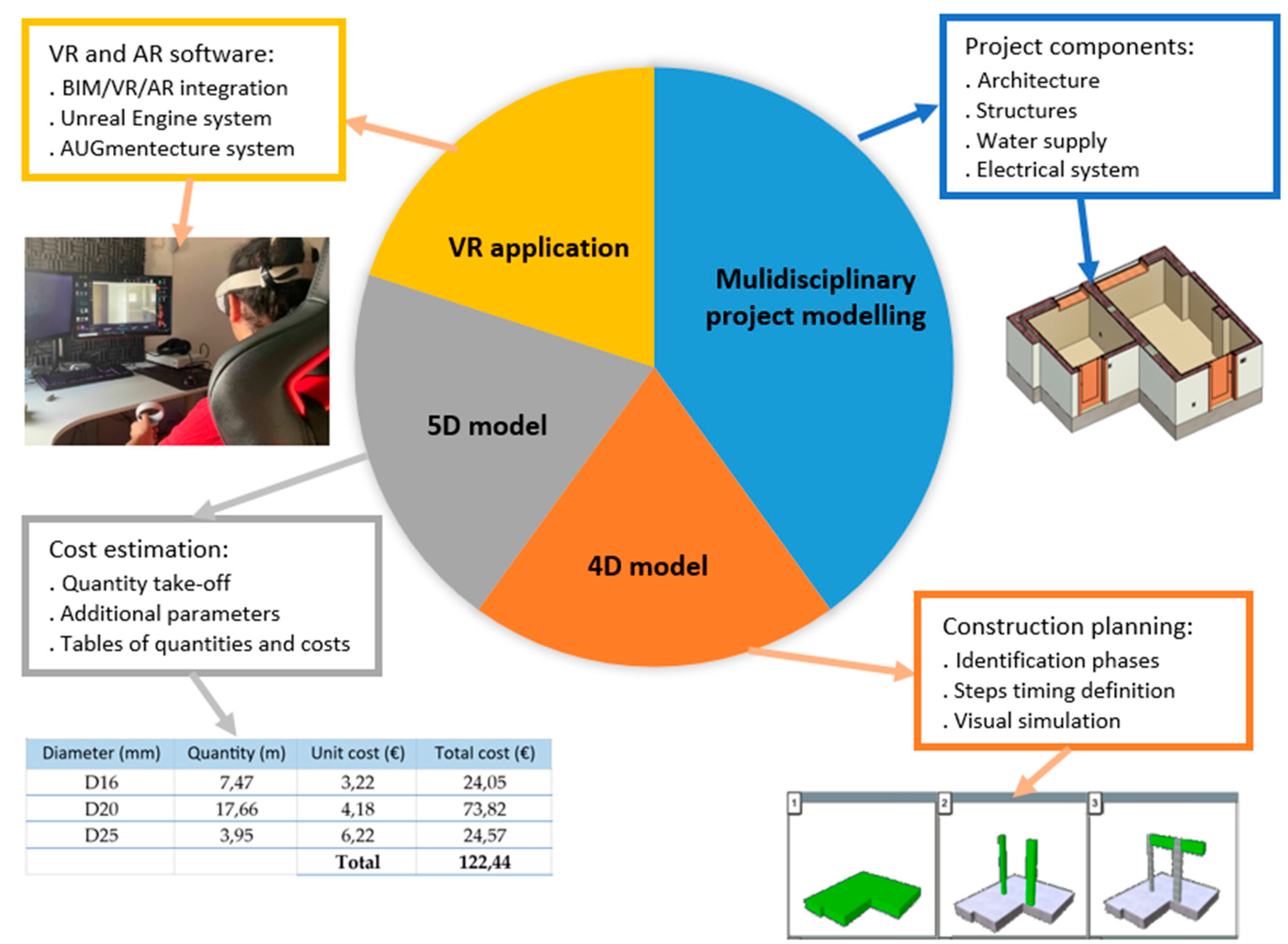
Figure 2.
The Sensorama Machine (a), Head-Mounted Display (b) and Sword of Damocles (c).
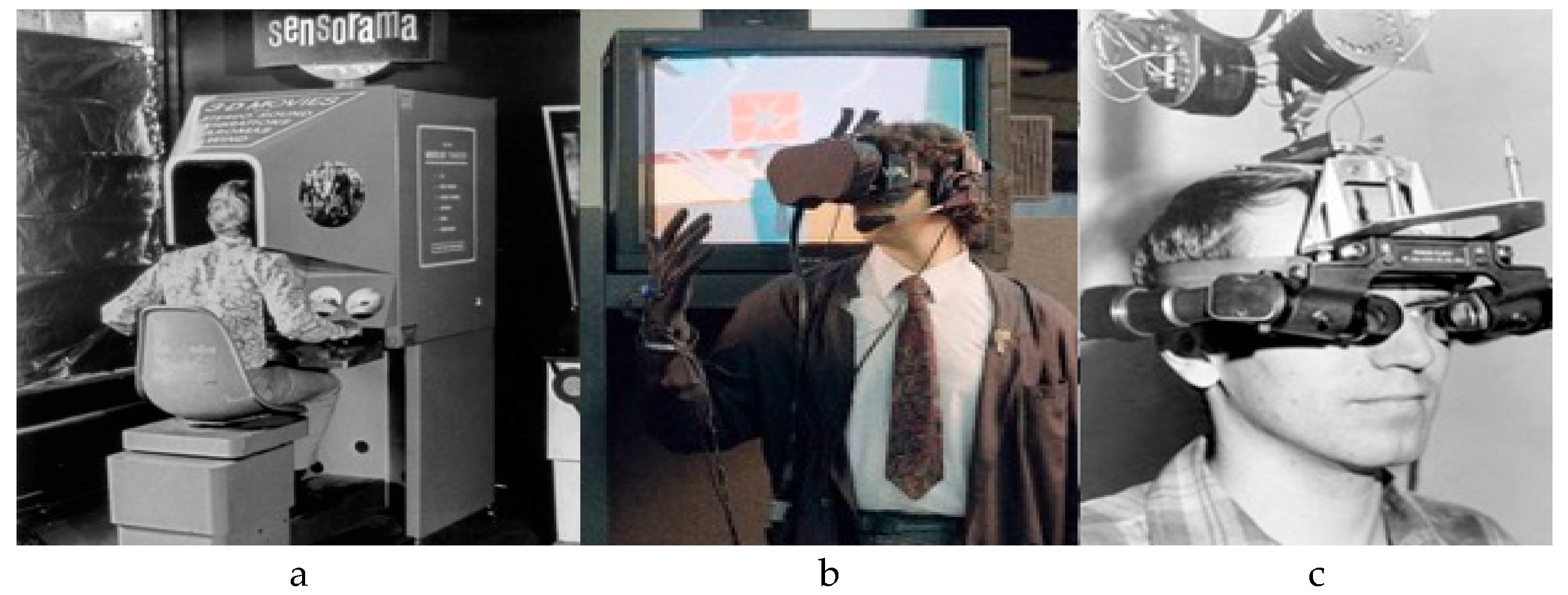
Figure 3.
Composition of the parametric objects representative of the walls (a) and their insertion in the model (b).
Figure 3.
Composition of the parametric objects representative of the walls (a) and their insertion in the model (b).
Figure 4.
Features considered for the new ceramic coating material.
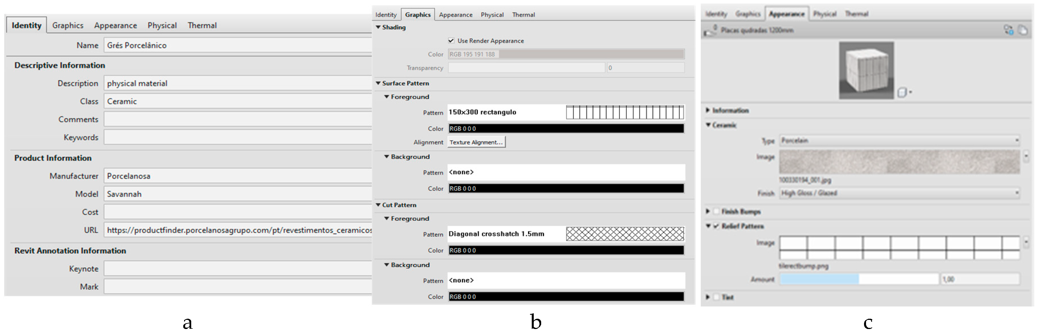
Figure 5.
Representation of the floor, walls and roof of the model, in vertical cut (a) and in perspective (b).
Figure 5.
Representation of the floor, walls and roof of the model, in vertical cut (a) and in perspective (b).
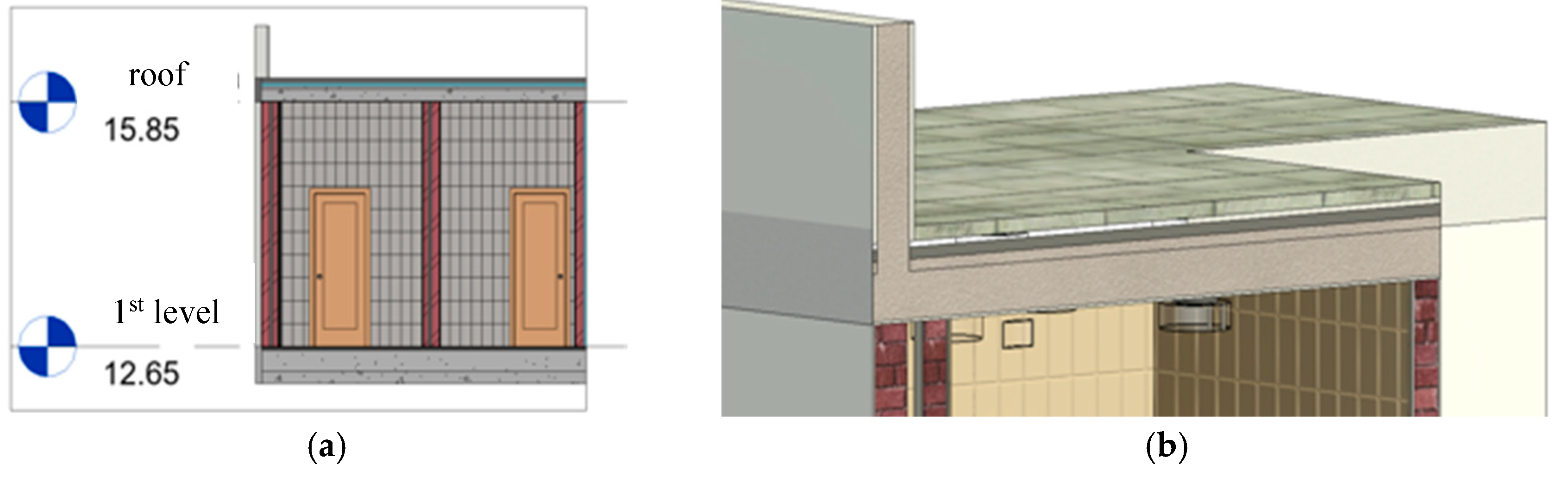
Figure 6.
Model of the structural component.
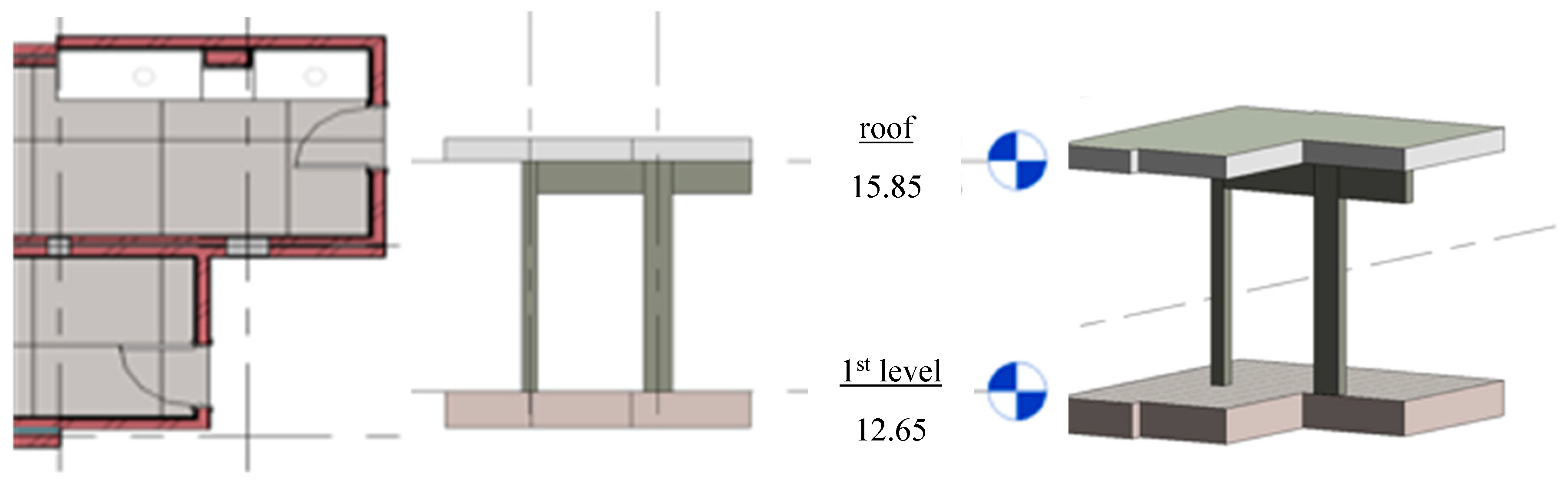
Figure 7.
Sanitary devices inserted in the model (a) and water supply network (b).
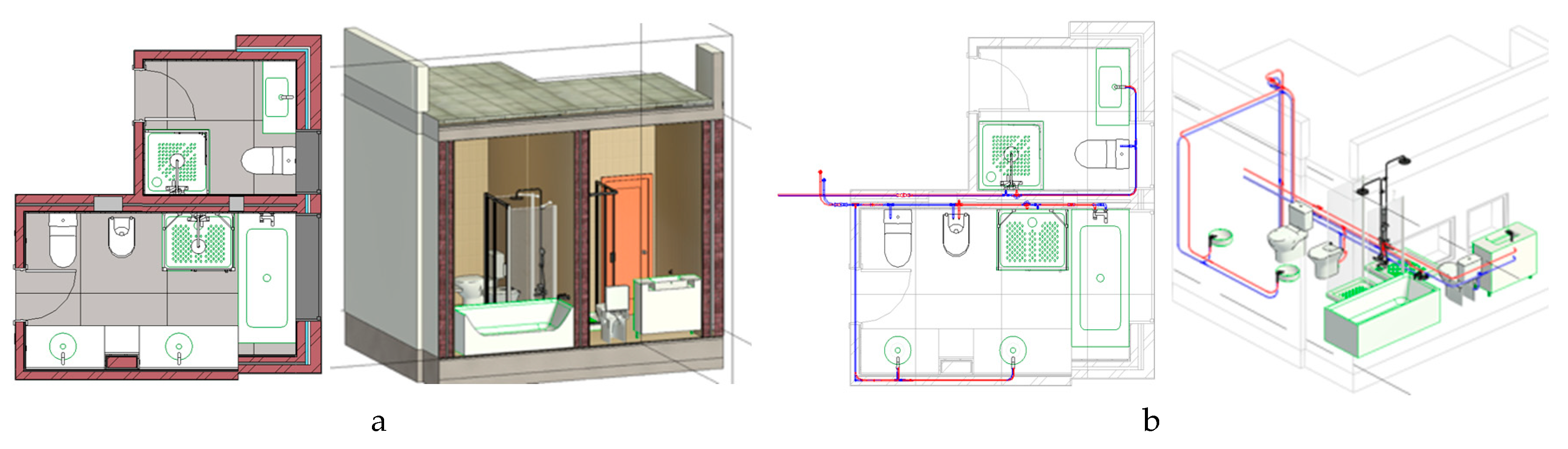
Figure 8.
Readjusted water distribution network (a) and drainage network (b).
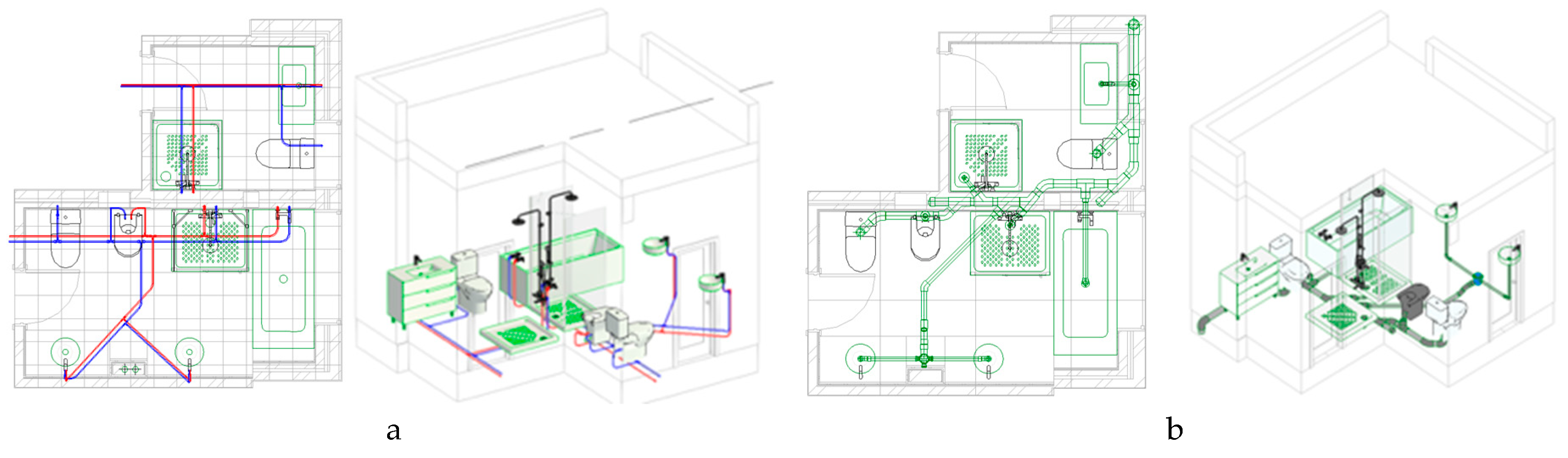
Figure 9.
Electrical network.
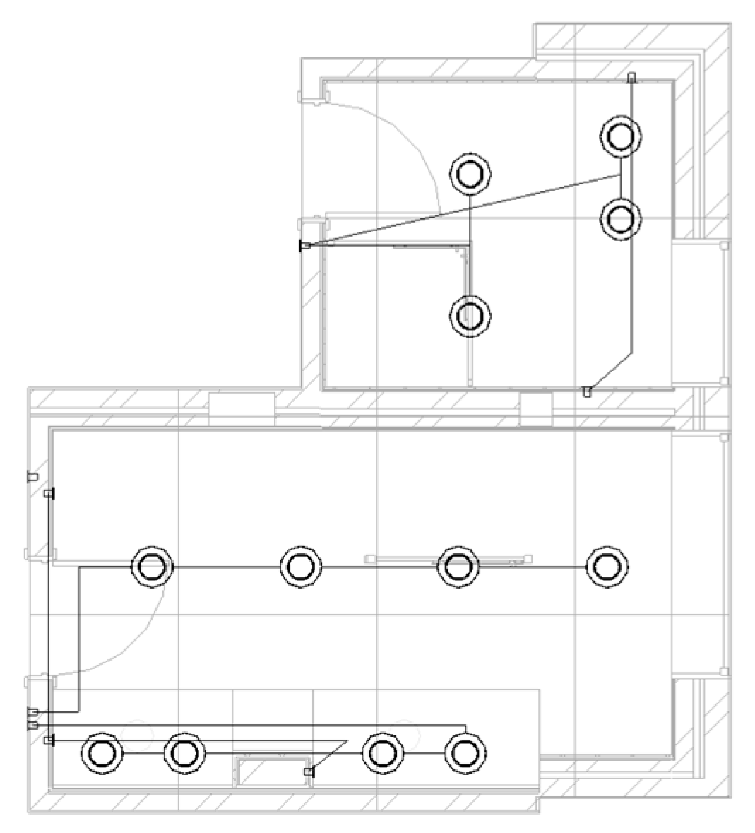
Figure 10.
Simplified Gantt chart.
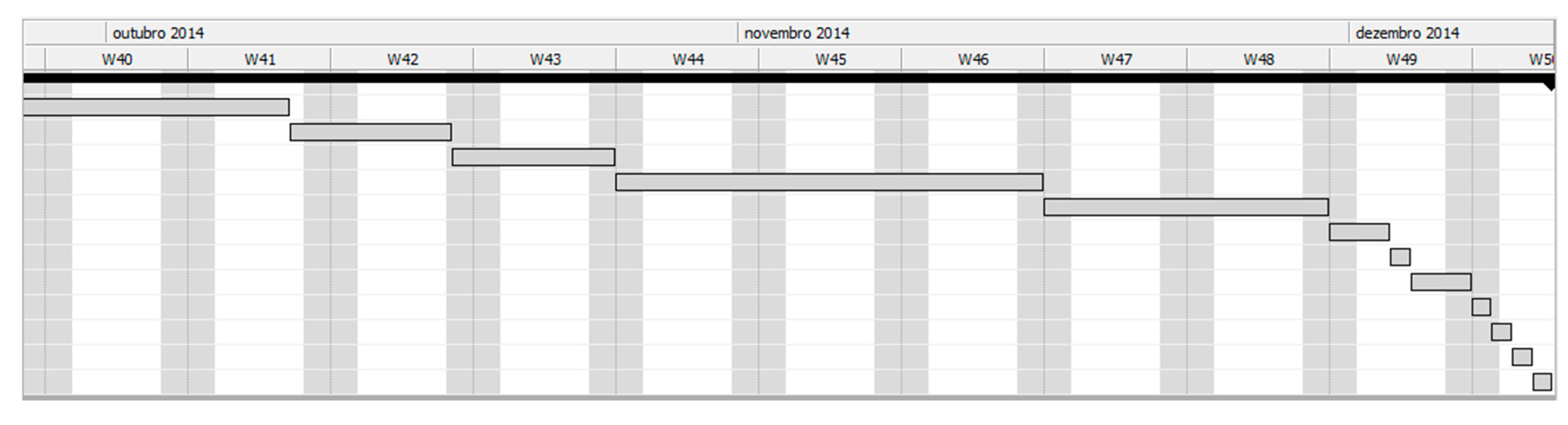
Figure 11.
Sequence of the visual simulation of the planned work.
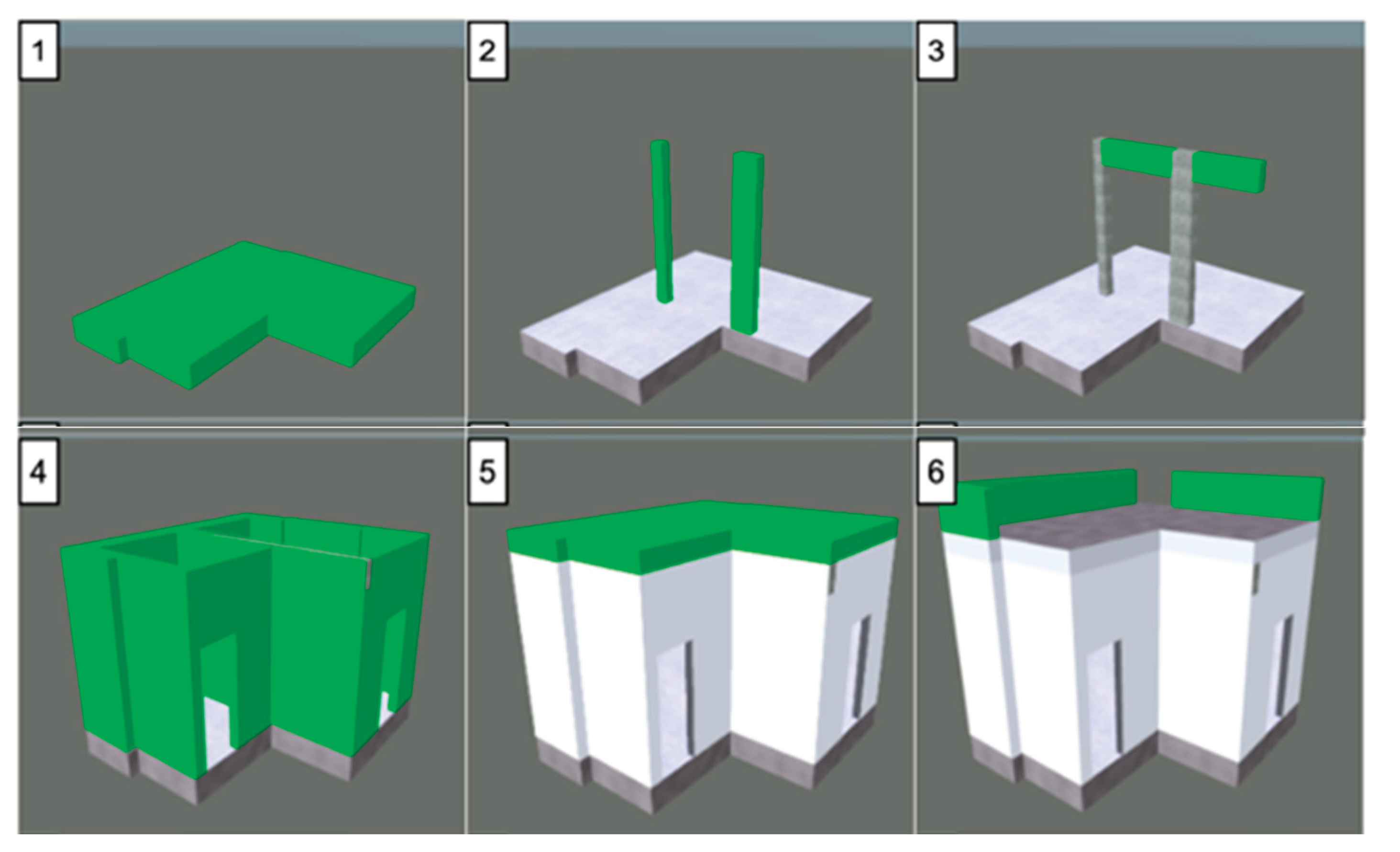
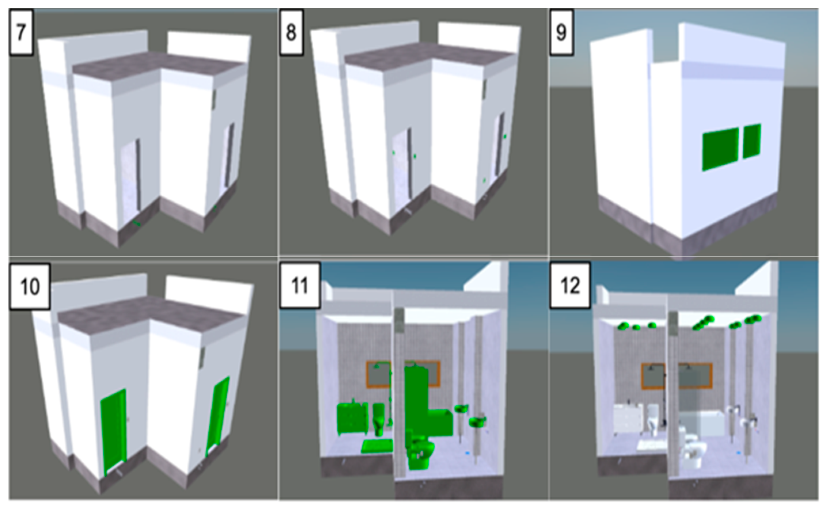
Figure 12.
Visualization of the VR model with an error (a) and after correction (b) and the photography of the real space (c).
Figure 12.
Visualization of the VR model with an error (a) and after correction (b) and the photography of the real space (c).
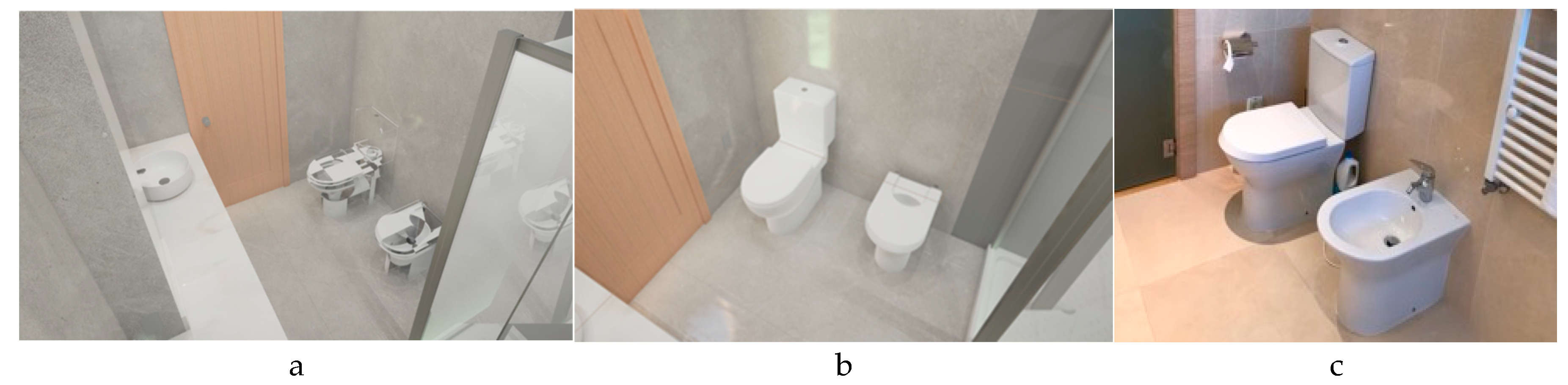
Figure 13.
User manipulating the model in Unreal Engine software using Meta Quest 2 devices (a) and the identification of user position and orientation (b).
Figure 13.
User manipulating the model in Unreal Engine software using Meta Quest 2 devices (a) and the identification of user position and orientation (b).
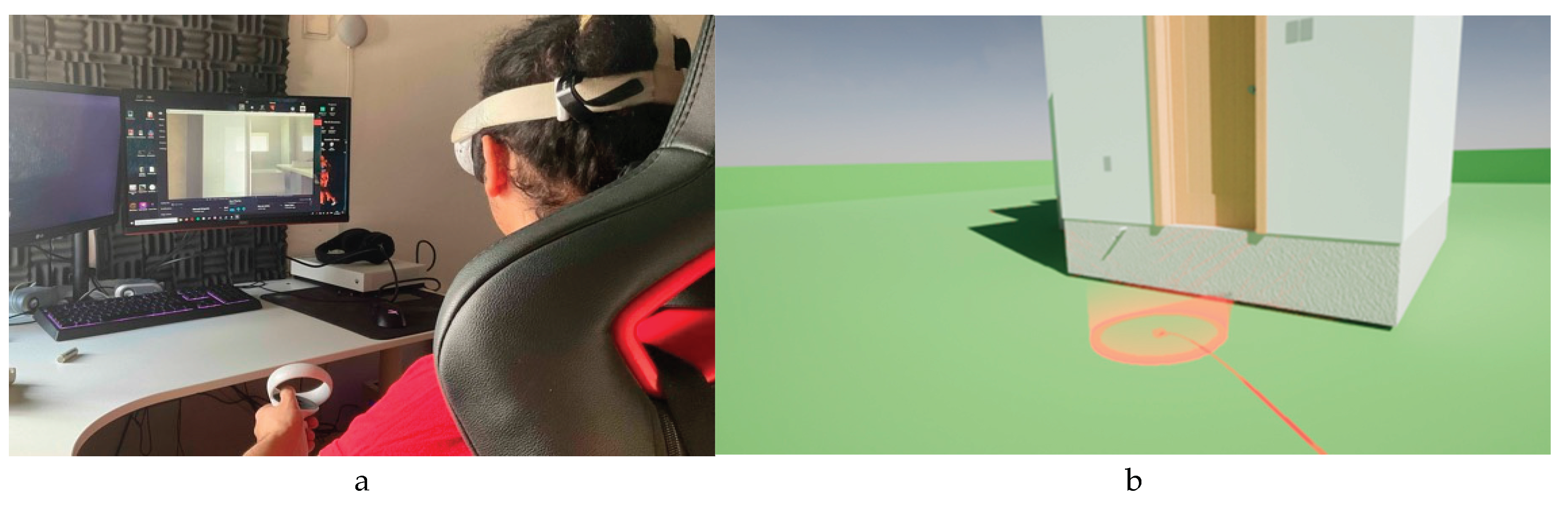
Figure 14.
Model imported by the AUGmentecture software (a) and the use of the AUG 3D Viewer option.
Figure 14.
Model imported by the AUGmentecture software (a) and the use of the AUG 3D Viewer option.
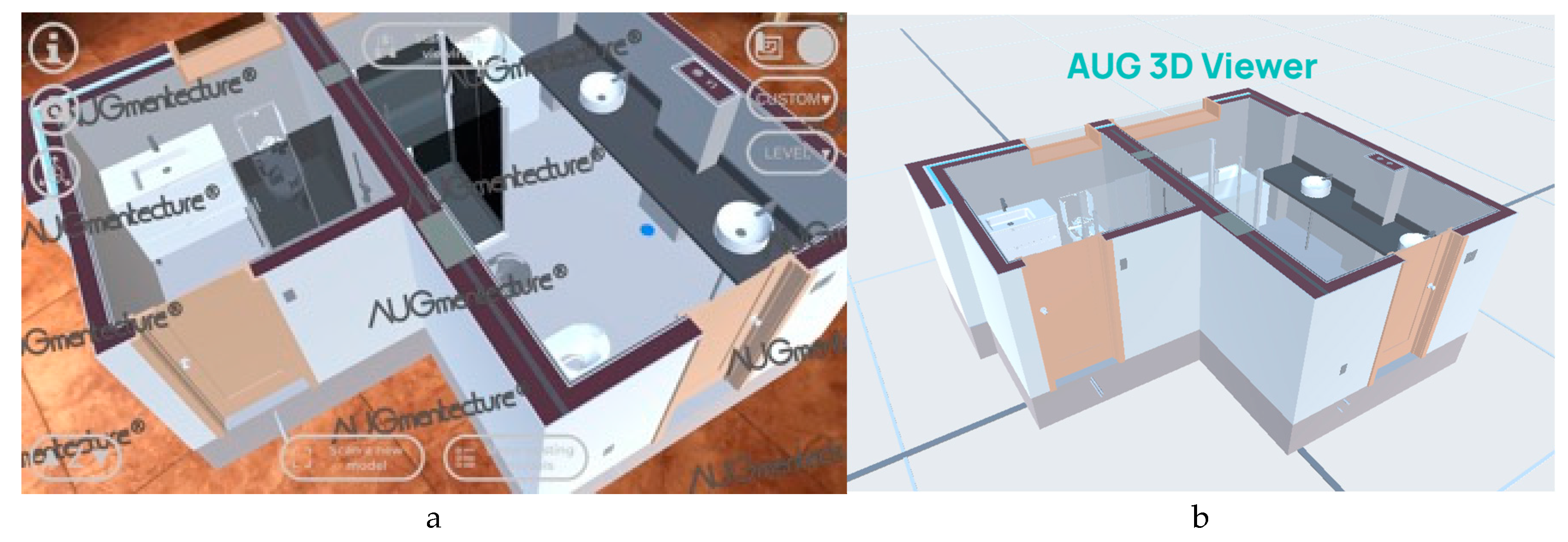

Table 1.
Calculation of the activity time associated with the floor slab execution.
| Activity | Quantity m-h/uni. | Unity | Men | Quantity | Uni. | Hours |
| Concreting | 1.250 | m.h/m³ | 2 | 2.6 | m³ | 2 |
| Armor (D10 mm) | 0.315 | m.h/10kg | 2 | 212.5 | kg | 3 |
| Armor (D12 mm) | 0.283 | m.h/10kg | 2 | 118.8 | kg | 2 |
| Formwork | 2.500 | m.h/m² | 2 | 16.0 | m² | 20 |
| Shape layer application | 1.550 | m.h/m² | 2 | 16.0 | m² | 12 |
| Application of screed | 0.940 | m.h/m² | 2 | 16.0 | m² | 8 |
| Laying porcelain stoneware | 1.390 | m.h/m² | 2 | 16.0 | m² | 11 |
| Total | 58 |
Table 2.
Calculation of the periods of construction associated with the exterior walls.
| Activity | Quantity (m-h/m2) | Men | Quantity (m2) | Hours |
| Execution of 15cm brick masonry | 2.215 | 2 | 16 | 17.7 |
| Execution of 11cm brick masonry | 2.923 | 2 | 16 | 23.4 |
| Paint application | 0.400 | 2 | 16 | 3.2 |
| Laying thermal insulation | 0.400 | 2 | 16 | 3.2 |
| Plastering application | 2.440 | 2 | 16 | 19.5 |
| Laying porcelain stoneware | 0.900 | 2 | 16 | 7.2 |
| Total | 73.2 |
Table 3.
Costs of multilayer pipe segments.
| Diameter (mm) | Quantity (m) | Unit cost (€/m) | Total cost (€) |
| D16 | 7,47 | 3,22 | 24,05 |
| D20 | 17,66 | 4,18 | 73,82 |
| D25 | 3,95 | 6,22 | 24,57 |
| Total | 122,44 |
Table 4.
Costs of PVC pipe segments.
| Diameter (mm) | Quantity (m) | Unit cost (€/m) | Total cost (€) |
| D32 | 2 | 5,06 | 10,12 |
| D40 | 2,2 | 5,69 | 12,52 |
| D50 | 1,26 | 6,73 | 8,48 |
| D75 | 1,54 | 8,22 | 12,66 |
| D90 | 2,24 | 10,02 | 22,44 |
| D110 | 0,99 | 12,6 | 12,47 |
| Total | 78,70 |
Disclaimer/Publisher’s Note: The statements, opinions and data contained in all publications are solely those of the individual author(s) and contributor(s) and not of MDPI and/or the editor(s). MDPI and/or the editor(s) disclaim responsibility for any injury to people or property resulting from any ideas, methods, instructions or products referred to in the content. |
© 2025 by the authors. Licensee MDPI, Basel, Switzerland. This article is an open access article distributed under the terms and conditions of the Creative Commons Attribution (CC BY) license (http://creativecommons.org/licenses/by/4.0/).
Copyright: This open access article is published under a Creative Commons CC BY 4.0 license, which permit the free download, distribution, and reuse, provided that the author and preprint are cited in any reuse.


