
Submitted:
05 August 2025
Posted:
06 August 2025
You are already at the latest version
Abstract
Schenberg is a resonant mass gravitational wave (GW) detector built in Brazil, it works by the detection of vibrations when a GW passes through a spherical mass and excites it quadrupole vibrational modes. The sphere is a 65 cm in diameter made of Cu 6% Al alloy casted in Brazil, this alloy was chosen because it can be cooled down to milliKelvin temperatures with a good mechanical quality factor. The quadrupole mode frequencies were measured at 4 Kelvin and presented a frequency band of about 67.5 Hz. This sphere was simulated in SolidWork FEM software and the band calculated for a free sphere was of about 30 Hz. Another simulation was made with Ansys and the same result was obtained. Then the suspension was included in the simulation and the same results persisted, then gravity was included which made the bandwidth even smaller. Finally a close bandwidth to the measured one was obtained including variation on the sphere microstructure due to differences in cooling time during the sphere casting, for a good mechanical quality factor the sphere did not have a homogenization. In order to reach the correct frequency modes distribution a small deviation from the vertical axle was needed and a reasonable frequency distribution was found.
Keywords:
Schenberg detector
; quadrupole frequencies
; microstructure
; symmetry breaking
; sphere casting
1. Introduction
Gravitational waves (GW) were theoretically predicted by A. Einstein more than a century ago as a consequence of general relativity (GR). After many decades of debates and experimental developments, the announcement of the first successful direct detection of these waves was delivered in 2015 by the LIGO-Virgo collaboration [1]. In GR gravitational waves are modeled as space-time distortions that propagate at the speed of light. They are expected to weakly interact with matter, and in massive objects they would excite their normal modes. This behavior led to the construction of GW detectors with resonant-mass technology long before the present interferometric GW detectors (IGD) were designed [2].
Resonant-mass GW detectors (RMD) are nowadays being investigated as a technology to pursue in collaboration with the interferometric ones. RMD are cheaper to build and have narrower bandwidth, making them useful, for instance, to aid in the calibration of the large interferometers or for coincidence detection with the latter to confirm GW arrival [3].
A particularly efficient geometry for a RMD is the sphere, whose symmetry favors omnidirectionality in respect to the GW direction of arrival. In principle, a spherical RMD should be able to yield the direction of arrival of a GW [4,5,6,7], an information that is not possible to acquire from a single IGD. Indeed, in the first direct detection of GW by the LIGO-Virgo-Kagra collaboration the direction of the source was possible to be obtained because all three interferometers of the collaboration were working in coincidence [8].
A prototype of a spherical RMD has been developed, named SCHENBERG in memory of the Brazilian scientist Mario Schenberg, known for his remarkable astrophysical studies. A schematics of the detector can be seen in Figure 1. Data from this prototype was collected in a few runs, aimed at testing the technology for a possible larger detector [9,10]. The SCHENBERG prototype could work as a detector if GW around 3200 Hz arrived with enough intensity. The coalescence of a binary system involving a neutron star and a black hole (NS-BH merger) is expected to emit strong GW in a wide spectrum of frequencies that encompasses SCHENBERG’S band. With enough sensitivity this detector would have a significant chance of detecting NS-BH mergers of 1.4 – 3.0 [11]. The unique symmetry of this RMD could also be used to investigate whether space-time ripples could be scaled by a tiny action, for which sensitivities beyond the standard quantum limit are needed [12]. As well, SCHENBERG could also allow the test of alternative theories of gravitation, as in the work by de Paula et al. [13] that involves a massive graviton, implying six polarization states.
The geometric symmetry of the massive sphere that acts as a GW antenna in SCHENBERG is essential for its best performance. The transducers that detect the antenna’s subtle motions are also distributed throughout the surface following the symmetrical shape of a truncated icosahedron [14]. They allow the monitoring of the sphere’s five quadrupole modes that mechanically vibrate in the presence of a GW within the band of 3.15 - 3.26 kHz. SCHENBERG’s antenna is made of a CuAl(6%) alloy with high mechanical quality factor when operating at low temperatures (∼ 4K), weighing 1124kg with a radius of 32.33cm. Details on the transducers, suspension system and cryogenics can be found in the literature [15,16,17,18,19,20,21].
In this work we investigate how the quadrupole frequencies of SCHENBERG sphere are influenced by breaking of symmetric due to many factors: hole for the suspension, presence of gravity and microstructure of the sphere caused by the casting process. The goal is to find the correct bandwidth of the sphere quadrupole modes. In Sect. 2 SCHENBERG sensitivity curve is explained. In Sect. 3 a summary on the interaction of GW with matter is presented. In Sect. 4 the symmetry breaking processes in the spherical antenna are presented. In Sect. 5 a FEM modeling of the spherical antenna in the presence of gravity is presented. In Sect. 6 a new perspective in the importance of the sphere’s microstructure is presented. In Sect. 7 a FEM model for the inhomogeneous sphere and its consequences are presented. Finally in Sect. 8 the conclusions are presented.
2. SCHENBERG’s sensitivity curve with 6 transducers
The solutions of the equation of motion for the displacement vector field of a solid spherical body subjected to an external force density and to the boundary condition of zero tension at its surface are the natural modes of the sphere. They involve two families of solutions: toroidal modes and spheroidal modes [22]. Toroidal modes do not generate radial motion and SCHENBERG’s transducers are not sensitive to them, nor these modes are excited by GW. On the other hand, in general relativity GW are quadrupolar, implying that only the 5 spheroidal quadrupolar modes of the antenna couple to a GW, allowing the detection of the latter through the antenna’s mechanical response. For SCHENBERG’s physical characteristics these 5 degenerate modes have a frequency around 3.2 kHz.
The mechanical oscillations of SCHENBERG’s antenna are monitored by transducers positioned in its surface. Johnson and Merkowitz [23] showed how the output of six transducers distributed on the antenna’s surface could be mathematically related to the quadrupolar modes of the sphere. This relation allows the determination of the parameters that characterize the incident GW from measured data [6,7].
SCHENBERG had nine transducers attached to the surface of its antenna, six of which were distributed according to the truncated icosahedron configuration proposed by Johnson and Merkowitz [14]. The other three transducers performed auxiliary functions [17,18,19,20,21]. Those 6 transducers introduced new resonant frequencies to the detector and enlarged its band. The mathematical model of the detector when the 6 transducers are added show the presence of 11 modes: 5 from the antenna and 6 from the transducers [11].
In general, a complex detector like SCHENBERG is subject to various kinds of noise that were extensively studied in order to be minimized and increase the detector’s sensitivity [11]. Noises that significantly influenced the detector’s performance were: thermal noise (from the antenna and the suspension system); noises from the dilution refrigerator and the mixing chamber; external noises.
One method to determine the influence of the noise on the detector’s sensitivity is to calculate its GW-equivalent signal, i.e., to determine its intensity as if it was a GW hitting the detector [11]. Figure 2 shows a typical sensitivity curve for SCHENBERG in the presence of noise with 6 transducers distributed according to the truncated icosahedron geometry in one of the antenna’s hemispheres [11]. The curve basically shows the energy spectrum in the output of the detector (in a convenient unit) as a function of frequency when no GW is present, thus presenting how the coupled system behaves in the frequency domain in view of its physical characteristics. Particularly important for this study are the 3 lowest dips of this figure, between 3080 Hz and 3170 Hz. They indicate the frequencies of the antenna’s quadrupole modes for a perfect sphere coupled with the transducer, which we will discuss in detail below.
3. Summary on the interaction of GW with matter
A GW generates a tidal force on any matter located at time t and at position , whose density is given by
where a sum over repeated indices is implied and . The letter represents the mass density of the matter and the second time derivative of the GW amplitude, .
Since SCHENBERG’S antenna should resonate with GW with frequencies about 3 kHz, the wavelength of such detectable GW is about 100 km since in GR these waves are expected to travel at the speed of light in vacuum (c). Therefore, the antenna can be considered small enough relative to the wave’s wavelength to allow the use in the calculations of the value of only at the center of the sphere.
The solution of (1) introduces spherical harmonics, from which only quadrupole modes remain for GW given by GR [24]. This simplification allows the modeling of the action of a GW on SCHENBERG’S antenna both analytically and computationally for many cases of interest.
We now focus on the mechanical response of SCHENBERG to external forces, which include forces due to GW. The equation of motion for the displacement vector field of a solid subjected to an external force density is given by [25]
where and are, respectively, the tangential and volumetric Lamé coefficients of the material, with initial conditions and . This problem has been solved in the literature [26]. In particular, in the description of the motion of the surface of an uncoupled sphere (free of tension on its surface) spheroidal modes are found to be the relevant ones considering the kind of transducers used in SCHENBERG, which detect radial motions only. For this reason these are the modes used in this work to monitor the sphere’s motion.
4. Symmetry breaking in the spherical antenna
Although SCHENBERG’s antenna was designed with a symmetric, very well studied geometry (the sphere), the need for suspension resulted in changes in the geometry. One important modification was the drilling of a hole through one axis of the sphere to host the suspension at its center, which made the antenna no longer a perfect sphere and resulted in more complex calculations.
For a perfect sphere the frequencies of the 5 quadrupole vibrational modes are degenerate, all having the same value of ∼3.2 KHz. Regarding mode vibration, one of the modes () is called prolate-oblate because its vibration causes the sphere to change from a prolate to an oblate shape. The other four modes are rotations of a motion in which the poles that move the most in the prolate-oblate mode stay still. These 4 modes resemble a tangerine with four segments where 2 opposite segments vibrate in phase while the other 2 segments vibrate in phase opposition. Two of these modes ( and ) differ only by a 45 degree rotation relative to the poles. The other two modes ( and ) behave similarly, but the axis through the poles is rotated 45 degrees in one direction plus another 45 degrees in a different direction. In Figure 3 the modes are displayed.
As the hole is machined in the sphere there is a break in the spherical symmetry. Suppose the hole was machined in the direction of the two poles that vibrate in the prolate-oblate mode. It breaks the spherical symmetry and the prolate-oblate mode has its frequency changed in a way different from the frequency change in modes and , which also differs from modes and . The 5 modes shift from a quintuplet configuration to a configuration with two doublets and a singlet.
The spherical symmetry is also broken by machining 9 small holes to house the transducers in the upper hemisphere. The study and evaluation of the new frequencies is no longer analytical and it is performed through simulations with finite element modeling (FEM); in this work the FEM program used was SolidWorks and Ansys SpaceClaim TM. Using this method several sets of definitions can be adopted, like the mesh size or the presence of gravity, normally affecting the results obtained and having a great impact on the simulation running time. The two programs got the same results for the sphere quadrupole modes of a homogeneous sphere not symmetrical.

Table 1.
Parameters of the Schenberg antenna. Source: Adapted from [11]
Table 1.
Parameters of the Schenberg antenna. Source: Adapted from [11]
| Description | Value | Method |
|---|---|---|
| 3 Quadrupole frequencies at 2 K | 3172.485, 3213.623, 3222.900 ± Hz | measured |
| 2 Quadrupole frequencies at 2 K | 3183, 3240 ± Hz | measured |
| Quadrupole frequencies at 300 K | 3045, 3056, 3086, 3095, 3102 ± | measured |
| Monopole frequency at 300 K | measured | |
| Antenna’s radius at 300 K | measured | |
| Antenna mass | measured | |
| Antenna’s density at 300 K | measured | |
| Transducer first stage mass | measured | |
| Transducer second stage mass | measured | |
| Monopole frequency at 4 K | calculated | |
| Mean quadrupole frequency at 4 K | calculated | |
| Longitudinal sound velocity at 4 K | calculated [11] | |
| Transversal sound velocity at 4 K | calculated [11] | |
| Linear thermal expansion coef. at 273.15 K | reference [28] | |
| Weight average of CuAl6 Debye temp. | reference [29] | |
| Weight average of CuAl6 Fermi temp. | reference [29] | |
| Weight average CuAl6 Gruneisen coef. | reference [30] | |
| Sound velocities ratio | calculated [11] | |
| Poisson ratio | calculated [11] | |
| Sphere radius as 4 K | calculated [11] | |
| Sphere density at 4 K | calculated | |
| Volumetric Lamé coefficient | calculated [11] | |
| Tangential Lamé coefficient | calculated [11] | |
| Young modulus | calculated [11] | |
| Bulk modulus | calculated [11] | |
| Chi factor | calculated [11] | |
| Radial component factor at | ||
| Antenna equivalent mass | ||
| Antenna effective mass | ||
| Transducer amplification factor | 4740 |
Using FEM SolidWorks and Ansys SpaceClaim TM, performed a simulation considering all the details of an sphere in the absence and presence of gravity, while in an experiment with the sphere [27] the quadrupole frequencies were identified. As can be seen in Table 2, a significant difference in the bandwidth of the quadrupole modes was found between both results: the simulation yielded a bandwidth of 35 Hz while the experiment yielded a bandwidth of 67.5 Hz.
Also a small twist in gravity was tested (5 degree from the vertical direction) was tested to simulate a misaligmnent in the sphere suspension, but again, the results does not reproduced the measured quadrupole frequencies.
5. FEM model of the spherical antenna in the presence of gravity
In works done previously [31,32,33,34], the GW antenna was isolated from the rest of the experiment and free of the influence of gravity, which greatly simplified the problem and required a reasonable computer processing time.
In this work gravity is taken into account in the simulation to try and explain the quadrupole frequencies previously measured in the detector. This is done also by introducing a constraint in the location where the sphere is connected to the suspension [34]. Also, a small misalignment in the suspension mounting is included by considering gravity inclined by a small angle. This work was possible due the interdisciplinary research group involved.
In order to make the sphere a GW detector, 9 holes were drilled on its surface to house the transducers, 6 of which would specifically monitor the quadrupolar modes, positioned according to a half-dodecahedron distribution. Another transducer would act as a calibration device and two others would monitor monopolar vibrations (to aid in vetoing spurious signals). All these holes were included in the simulation, as well as an axial hole that contains in its center a conical shape surface where the suspension central rod is connected. Figure 4 displays the model containing the surface holes and the central conical surface where the sphere is connected to the suspension rod.
The study of the effect of gravity on SCHENBERG’s quadrupolar frequencies starts with a static analysis of gravity on its sphere. The gravitational force is applied vertically and the displacements caused by it are identified. In Figure 5 the result of the static simulation applying gravity to the sphere can be seen, including the iso-displacements of the spherical antenna due to its own weight. Iso-displacements belong to surfaces where the displacements have the same magnitude. We found that the surface of the sphere drops 0.8977 micrometers under the influence of gravity.
The same procedure was used to evaluate if some misalignment in the mounting of the suspension could be responsible for the scattering of the antenna mode frequencies. For this evaluation the direction of gravity was tilted by 5 degrees, which was the maximum angle that could be allowed in the mounting of the suspension without being detected in the mounting. This emulated a misalignment in the mounting.
We found (see Table 2) that the effect of gravity on the quadrupole frequencies was to increase the frequencies as a whole while reducing the bandwidth. We also noted that the increase in frequency was smaller the higher the doublet frequency. The absolute value of the frequencies is not important as it can be caused by differences in the material properties, but the decrease found in this case for the bandwidth does not solve the problem of the mismatch between the theoretical value of the bandwidth and the measured one.
As well, no frequency change due to the tilted gravity was obtained. Therefore, we found that no change in frequency due to small misalignment problems should be expected in actual detectors.
In both cases where gravity was included in the simulations, it is possible that the change on the antenna’s shape due to gravity might be responsible for the narrower bandwidth. Indeed, gravity is likely to make the sphere more prolate in the vertical direction, possibly favoring the oscillations of the quadrupole modes towards a dominant frequency. As a consequence of this part of our study, it seems that the gravitational pull is not responsible for the wider bandwidth found in the real detector. Therefore we proceeded to investigate another aspect, as follows.
6. A new perspective: the importance of the sphere’s microstructure
As the bandwidth of the measured frequencies seemed to have no explanation in terms of the gravitational pull, we hypothesized problems resulting from the FEM simulation program (two different programs were used yielding the same results) and problems due to the microstructure of the sphere (the quality factor of the sphere was too hith to allow any large discontinuities in the sphere macrostructure). However, we suspected that the main cause could lay in the microstructure.
Figure 6 shows the ingot from which SCHENBERG’s sphere was machined. The sphere was produced from the lower part of the ingot as the mechanical quality factor of this part should be higher, since the defects of the metal should move to the upper part during solidification when the ingot was casted.
During casting the ingot solidified faster on the sides and on the bottom. When the ingot was ready the sphere was machined from its lower part, in the region of the circle in Figure 7. It is important to note that, because of need for a high mechanical quality factor, the ingot was not homogenized.
The regions of the ingot on its side and on its bottom, which solidify faster, are known in the literature to become harder depending on the speed of the cooling process. Figure 8 shows how the hardness of the material changes with the cooling speed [35]. According to reference [35], the hardness and the Young modulus of the CuAl alloy can vary by 20%.
7. The FEM model for the inhomogeneous sphere
Given this new physical model that we devised for the sphere’s internal structure, the idea behind the FEM model was to separate the sphere’s volume in two parts, in which the external one was made of a material 20% harder than that of the internal part, as seen in Figure 9. To allow for a small difference in the cooling distribution according to the directions, a mismatch of 5 cm was created for the vertical symmetry axis of the internal part relative to the vertical symmetry axis of the external part. This mismatch is essential to break the suppose duplet from modes and , this mismatch will break it as it appears in the measurements.
Using this model, 3 different simulations were performed, as there is no access to the actual internal structure of the material. The idea was to make the 3 simulations and check if any of the results yielded the measured bandwidth. The dimensions used in each case are presented in Table 3. The cylinder’s diameter was kept constant as the microstructure model of Figure 7 indicates that this diameter is central enough to basically not change in the casting.
Once the dimensions were chosen for each case, then the Young modulus of the parts were determined, aiming at a total variation from 20% to 30% as argued above. The values that yielded the best bandwidth results for each case are presented in Table 4. The Sphere II case demanded a larger variation between the Young modulus of each part in order to yield an interesting bandwidth.
Figure 10, Figure 11 and Figure 12 show the results of the FEM simulations. In Figure 10 the vibrational shapes of the 5 quadrupolar modes are shown with their respective frequencies for the Sphere I case, which has a bottom thickness of intermediate width, chosen to be equal to the radius of the internal cylinder for symmetry. Also, the internal part is softer than the external one by . The bandwidth obtained from this simulation was 52.5 Hz, a value 22.2% smaller than the experimental value presented in Table 2 (67.5 Hz) but quite better than the bandwidth of 35.0 Hz obtained from the simulation of a homogeneous sphere. The antenna’s vibrations are clearly less symmetric than those of the homogeneous sphere, shown in Figure 3.
Figure 11 shows the vibrational shapes and their respective frequencies for the Sphere II case, which has the widest bottom thickness. The internal part is even softer than the external one (by 30%), compared to the Sphere I case. The bandwidth obtained from this simulation was 57.6 Hz, a 14.7% smaller than the experimental one (67.5 Hz) and a better result than the bandwidth of the homogeneous sphere. The antenna’s vibrations are quite less symmetric compared to those of the homogeneous sphere, shown in Figure 3. The result is better but this as the difference in the young modulus is too big, another simulation set up was made.
Figure 12 shows the vibrational shapes and their respective frequencies for the Sphere III case, which has the narrowest bottom thickness. The relation between the Young modulus of each part is the same of that of the Sphere I case. The bandwidth obtained from this simulation was 63,2 Hz, a value smaller than the experimental one by , a much better result than the bandwidth of the homogeneous sphere. The antenna’s vibrations are less symmetric compared to those of the homogeneous sphere, shown in Figure 3.
8. Conclusions
In this work we analyzed the spherical, resonant-mass gravitational wave antenna of the SCHENBERG detector under new physical circumstances: in the presence of gravity (with and without suspension tilt) and considering effects of the material microstructure on the antenna’s quadrupole mode frequencies. We accomplished these investigations simulating the antenna using FEM.
When analyzing the effect of the action of gravity on the frequencies of the quadrupole modes of SCHENBERG’s antenna, an increase in the frequency values was noted, as well as a reduction in its bandwidth, relative to the free sphere case. It was also noted that the increase in frequency was larger for doublets with lower frequency. This was an interesting result which, however, could not explain the experimental bandwidth. It confirmed numerically, on the other hand, that the effect of Earth’s gravitational pull on the antenna is not expected to significantly influence the detector’s signal.
Through an unprecedented analysis of the antenna’s microstructure resulting from the casting process, we created an original numerical model to apply in the FEM study of 3 cases. The cases also included different hardness throughout the sphere’s volume. The best bandwidth found among these cases was 63.5 Hz (Sphere III), the closest to the measured bandwidth of 67.5 Hz. This case involved an external part harder than the internal part and with a relatively thin bottom.
On the other hand, it is possible that more accurate measurements of the detector bandwidth could result in a narrower bandwidth for SCHENBERG’s quadrupole frequencies. In this case, the Sphere III model would be even more precise in describing the antenna’s physical model. Consequently, better theoretical models could be developed in regard to GW characterization from SCHENBERG’s data.
The simulations performed in this research show that the microstructure of the metal that constitutes the spherical antenna plays a significant role in the determination of the quadrupole modes’ bandwidth of the SCHENBERG GW detector. This microstructure is in general not symmetrically distributed when the antenna is casted, a feature that enhances its influence on the detector’s performance.
In the continuation of this work all the quadrupole frequencies will be analyzed in detail to obtain a better description of the system. In the future it is possible that the analysis of the vibrational frequencies can be used to identify the internal microstructure.
Author Contributions
Conceptualization, C.F. and N.S.M.; methodology, C.F, N.V.G, F.S.B and S.T.S; validation, C.F., N.S.M., N.V.G, F.S.B and S.T.S; formal analysis, C.F. and N.S.M.; investigation, C.F., N.S.M., N.V.G, F.S.B and S.T.S; resources, C.F., N.S.M., N.V.G, F.S.B and S.T.S; writing—original draft preparation, C.F. and N.S.M. ; writing—review and editing, C.F. and N.S.M.; visualization, C.F.; supervision, C.F, and N.S.M. ; funding acquisition, C.F. All authors have read and agreed to the published version of the manuscript.
Funding
This research received no external funding.
Institutional Review Board Statement
Not applicable.
Informed Consent Statement
Not applicable.
Data Availability Statement
Not applicable.
Acknowledgments
CF acknowledges FAPESP for support (thematic project #2013/26258-4) as well as CPNq (Brazil) for support (grant #312454/2021-0). The authors thank Vinicius Torres dos Santos for fruitful discussions.
Conflicts of Interest
The authors declare no conflicts of interest.
References
- Abbott, B.P.; Abbott, R.; Abbott, T.D.; Abernathy, M.R.; Acernese, F.; Ackley, K.; Adams, C.; Adams, T.; Addesso, P.; Adhikari, R.X.; et al. Observation of Gravitational Waves from a Binary Black Hole Merger. Physical Review Letters 2016, 116, 061102, [arXiv:gr-qc/1602.03837]. [Google Scholar] [CrossRef]
- Thorne, K.S. Sources of gravitational waves and prospects for their detection. In Proceedings of the Recent Advances in General Relativity. Essays in honor of Ted Newman; Janis, A.I.; Porter, J.R., Eds., 1992, pp. 196–229.
- Frajuca, C.; Prado, A.R.C.; Souza, M.A.; Magalhaes, N.S. The challenge of calibrating a laser-interferometric gravitational wave detector. Astronomische Nachrichten 2021, 342, 115–122. [Google Scholar] [CrossRef]
- Magalhaes, N.S.; Johnson, W.W.; Frajuca, C.; Aguiar, O.D. Determination of astrophysical parameters from the spherical gravitational wave detector data. Mnras 1995, 274, 670–678. [Google Scholar] [CrossRef]
- Magalhães, N.S.; Johnson, W.W.; Frajuca, C.; Aguiar, O.D. A Geometric Method for Location of Gravitational Wave Sources. Apj 1997, 475, 462–468. [Google Scholar] [CrossRef]
- Lenzi, C.H.; Magalhães, N.S.; Marinho, R.M.; Costa, C.A.; Araújo, H.A.B.; Aguiar, O.D. Solution of the inverse problem in spherical gravitational wave detectors using a model with independent bars. Phys. Rev. D 2008, 78, 062005. [Google Scholar] [CrossRef]
- Lenzi, C.H.; Magalhães, N.S.; Marinho, R.M.; Costa, C.A.; Araújo, H.A.B.; Aguiar, O.D. Astrophysics from data analysis of spherical gravitational wave detectors. Gen. Relativ. Gravit. 2008, 40, 183. [Google Scholar] [CrossRef]
- Abbott, B.P.; Abbott, R.; Abbott, T.D.; Acernese, F.; Ackley, K.; Adams, C.; Adams, T.; Addesso, P.; Adhikari, R.X.; Adya, V.B.; et al. GW170817: Observation of Gravitational Waves from a Binary Neutron Star Inspiral. Physical Review Letters 2017, 119, 161101, [arXiv:gr-qc/1710.05832]. [Google Scholar] [CrossRef]
- Aguiar, O.D.; Andrade, L.A.; Barroso, J.J.; Bortoli, F.; Carneiro, L.A.; Castro, P.J.; Costa, C.A.; Costa, K.M.F.; de Araujo, J.C.N.; de Lucena, A.U.; et al. The Brazilian gravitational wave detector Mario Schenberg: Status report. Classical and Quantum Gravity 2006, 23, S239–S244. [Google Scholar] [CrossRef]
- Aguiar, O.D.; Barroso, J.J.; Carvalho, N.C.; Castro, P.J.; M, C.E.C.n.; da Silva Costa, C.F.; de Araujo, J.C.N.; Evangelista, E.F.D.; Furtado, S.R.; Miranda, O.D.; et al. Status Report of the Schenberg Gravitational Wave Antenna. In Proceedings of the Journal of Physics Conference Series, 2012, Vol. 363, Journal of Physics Conference Series, p. 012003. [CrossRef]
- Liccardo, V.; Lenzi, C.; Marinho, R.; Aguiar, O.; Frajuca, C.; da Silva Bortoli, F.; Costa, C. The design strain sensitivity of the schenberg spherical resonant antenna for gravitational waves. Scientific Reports 2023, 13. [Google Scholar] [CrossRef] [PubMed]
- Messina, J.F. Question of Planckian “Action” in Gravitational Wave Detection Experiments. Progress in Physics 2015, 11, 202–203. [Google Scholar]
- de Paula, W.L.S.; Miranda, O.D.; Marinho, R.M. Polarization states of gravitational waves with a massive graviton. Classical and Quantum Gravity 2004, 21, 4595–4605. [Google Scholar] [CrossRef]
- Johnson, W.W.; Merkowitz, S.M. Truncated icosahedral gravitational wave antenna. Physical Review Letters 1993, 70, 2367–2370. [Google Scholar] [CrossRef]
- Melo, J.L.; Velloso, Jr., W. F.; Aguiar, O.D. Vibration isolation support design for the SCHENBERG detector. Classical and Quantum Gravity 2002, 19, 1985–1989. [Google Scholar] [CrossRef]
- da Silva Bortoli, F.; Frajuca, C.; de Sousa, S.T.; de Waard, A.; Magalhaes, N.S.; de Aguiar, O.D. On the Massive Antenna Suspension System in the Brazilian Gravitational Wave Detector SCHENBERG. Brazilian Journal of Physics 2016, 46, 308–315, Cited By :23. [Google Scholar] [CrossRef]
- de Paula, L.A.N.; Ferreira, E.C.; Carvalho, N.C.; Aguiar, O.D. High sensitivity niobium parametric transducer for the Mario Schenberg gravitational wave detector. Journal of Instrumentation 2015, 10, P03001. [Google Scholar] [CrossRef]
- Liccardo, V.; França, E.K.; Aguiar, O.D.; Oliveira, R.M.; Ribeiro, K.L.; Silva, M.M.N.F. Study of the effect of NbN on microwave Niobium cavities for gravitational wave detectors. Journal of Instrumentation 2016, 11, P07004. [Google Scholar] [CrossRef]
- da Silva Bortoli, F.; Frajuca, C.; Magalhaes, N.S.; Aguiar, O.D.; de Souza, S.T. On the Cabling Seismic Isolation for the Microwave Transducers of the Schenberg Detector. Brazilian Journal of Physics 2019, 49, 133–139, Cited By :15. [Google Scholar] [CrossRef]
- Frajuca, C.; Souza, M.A.; Coppedé, D.; Nogueira, P.R.M.; Bortoli, F.S.; Santos, G.A.; Nakamoto, F.Y. Optimization of a composite quadrupole mass at high-speed rotation. Journal of the Brazilian Society of Mechanical Sciences and Engineering 2018, 40. Cited By :13. [Google Scholar] [CrossRef]
- Bortoli, F.S.; Frajuca, C.; Magalhaes, N.S.; de Souza, S.T.; da Silva Junior, W.C. On the Dilution Refrigerator Thermal Connection for the SCHENBERG Gravitational Wave Detector. Brazilian Journal of Physics 2020, 50, 541–547, Cited By :8. [Google Scholar] [CrossRef]
- Lobo, J.A. What can we learn about gravitational wave physics with an elastic spherical antenna. Phys. Rev. D 1995, 52, 591–604. [Google Scholar] [CrossRef]
- Merkowitz, S.M.; Johnson, W.W. Techniques for detecting gravitational waves with a spherical antenna. Phys. Rev. D 1997, 56, 7513–7528. [Google Scholar] [CrossRef]
- Lobo, J.A. Multiple mode gravitational wave detection with a spherical antenna. Mnras 2000, 316, 173–194. [Google Scholar] [CrossRef]
- Landau, L.D.; Lifshitz, E.M. Theory of Elasticity, 3 ed.; Vol. 7, 6, Pergamon Press: Great Britain, 1986. [Google Scholar]
- Landau, L.D.; Lifshitz, E.M. Mechanique, 2 ed.; Vol. 1, 1, MIR: Moscou, 1966. [Google Scholar]
- Aguiar, O.; Andrade, L.; Barroso, J.; Camargo Filho, L.; Carneiro, L.; Castro, C.; Castro, P.; Costa, C.; Costa, K.; De Araujo, J.; et al. The Brazilian spherical detector: Progress and plans. Classical and Quantum Gravity 2004, 21, S457–S463. [Google Scholar] [CrossRef]
- Ross, R.B. Metallic Materials Specification Handbook; Springer, 1992.
- Ashcroft, N. W.; Mermin, N.D. Solid State Physics; Harcourt College Publishers, 1976.
- Callen, H.B. Thermodynamics; John Wiley & Sons, 1960.
- Frajuca, C.; Bortoli, F.D.S.; Magalhães, N.S. Resonant transducers for spherical gravitational wave detectors. Brazilian Journal of Physics 2005, 35, 1201–1203. [Google Scholar] [CrossRef]
- Frajuca, C.; Da Silva Bortoli, F.; Magalhaes, N.S. Studying a new shape for mechanical impedance matchers in Mario Schenberg transducers. 2006, Vol. 32, p. 319 – 322.
- Bortoli, F.; Frajuca, C.; Magalhaes, N.; Duarte, E. A physical criterion for validating the method used to design mechanical impedance matchers for Mario Schenberg’s transducers. 2010, Vol. 228.
- da Silva Bortoli, F.; Frajuca, C.; de Sousa, S.T.; de Waard, A.; Magalhaes, N.S.; de Aguiar, O.D. On the Massive Antenna Suspension System in the Brazilian Gravitational Wave Detector SCHENBERG. Brazilian Journal of Physics 2016, 46, 308–315. [Google Scholar] [CrossRef]
- Santo, V.T. Correlacao entre as Variaveis Termica de Solidificacao, Microestrutura, Microdureza e Dureza da Liga Bronze-Aluminio-Niquel CuAl10Ni5Fe5. Master’s thesis, Sao Paulo Federal Institute, 2017.
Figure 1.
Schematics of the SCHENBERG gravitational wave detector prototype. The spherical antenna is suspended by a rod attached to its center through a hole. Nine small holes were drilled on its surface for transducer attachment. Source: From the authors.
Figure 1.
Schematics of the SCHENBERG gravitational wave detector prototype. The spherical antenna is suspended by a rod attached to its center through a hole. Nine small holes were drilled on its surface for transducer attachment. Source: From the authors.
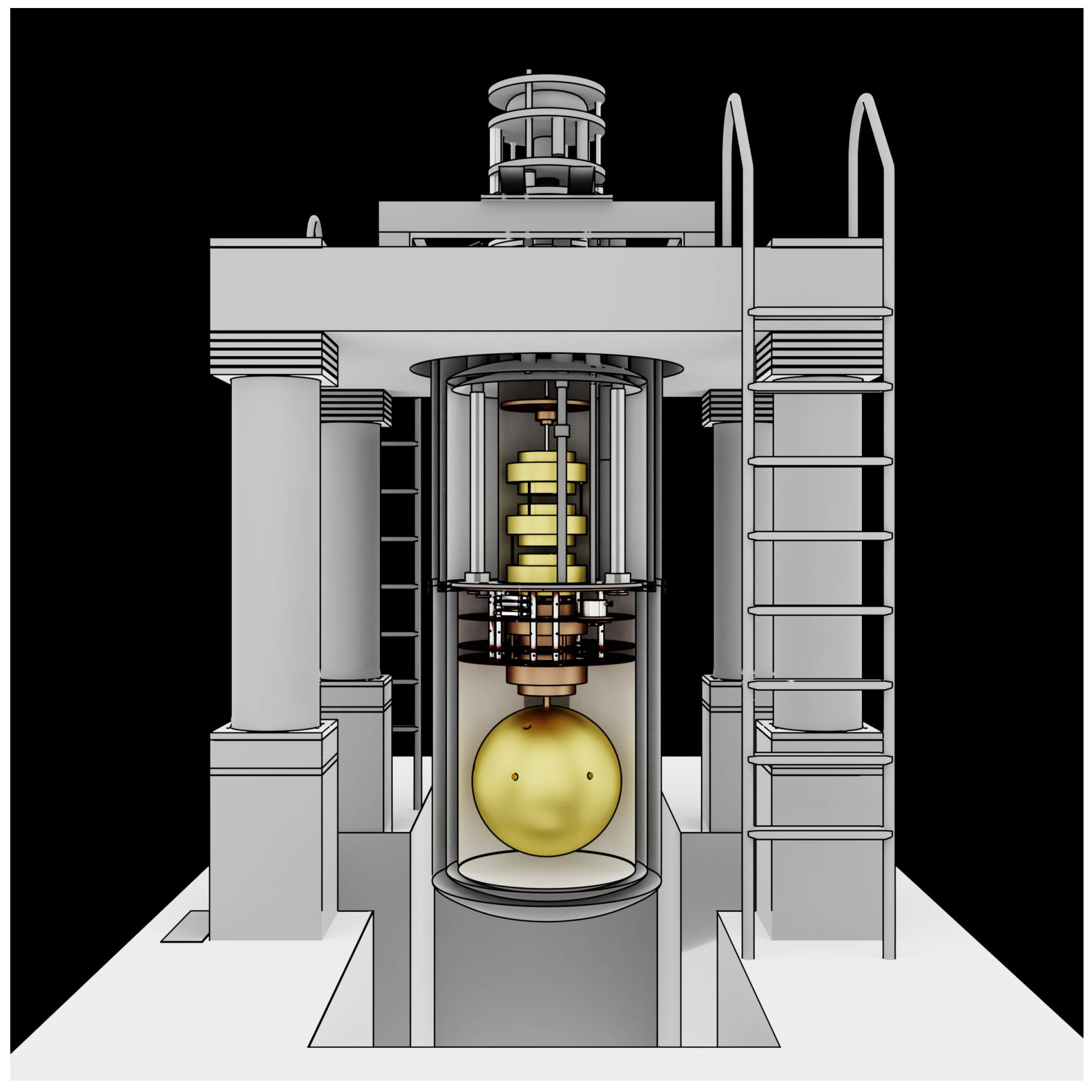
Figure 2.
Example of a theoretical sensitivity curve of SCHENBERG’s antenna coupled to 6 transducers attached to its surface in the presence of noise. The 3 lowest dips shown are related to the antenna’s quadrupole modes. Source: [11]
Figure 2.
Example of a theoretical sensitivity curve of SCHENBERG’s antenna coupled to 6 transducers attached to its surface in the presence of noise. The 3 lowest dips shown are related to the antenna’s quadrupole modes. Source: [11]
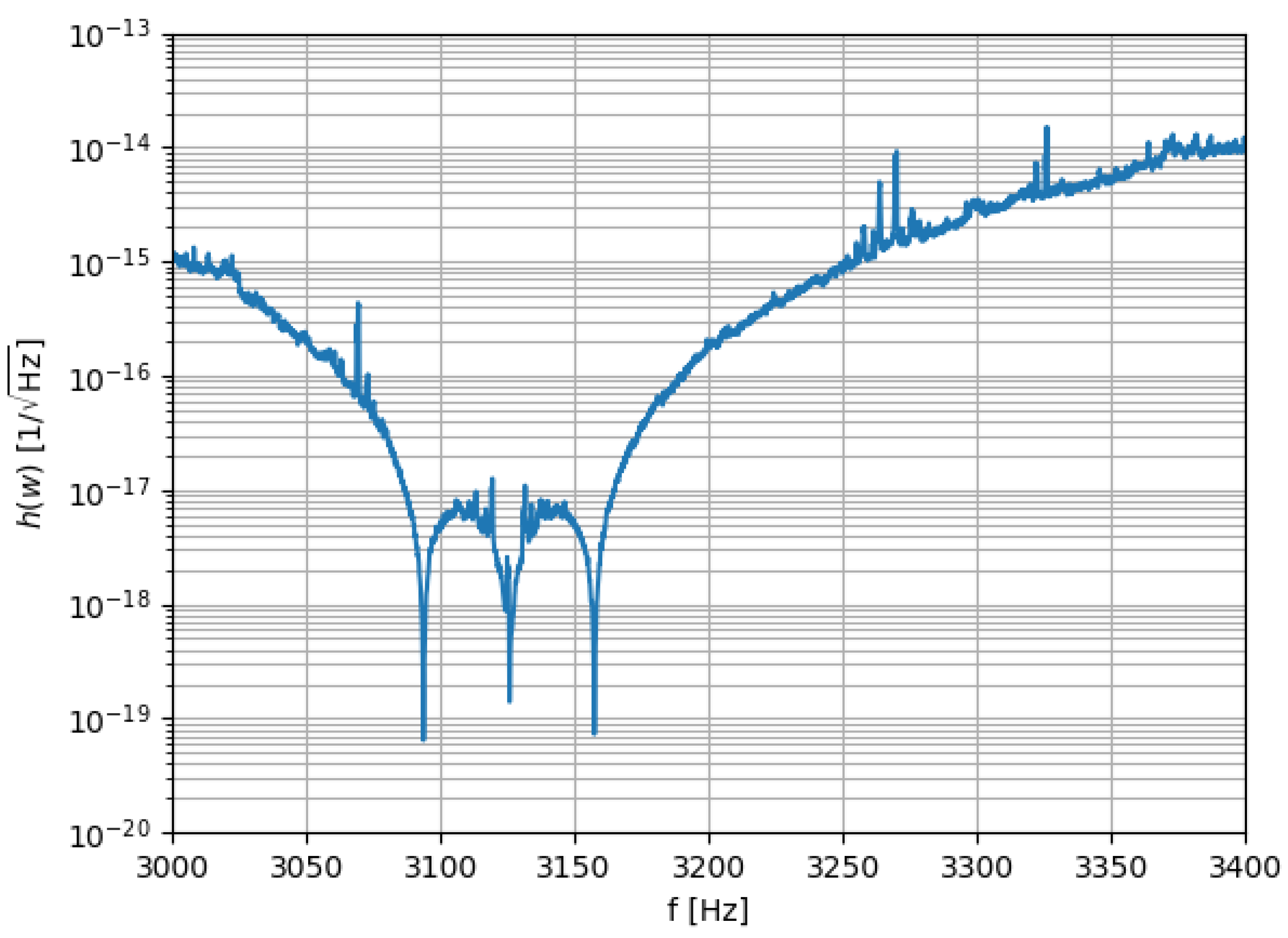
Figure 3.
Vibrations of the quadrupole modes of the spherical antenna. Red areas vibrate in phase opposition to blue areas. On the right is mode (prolate-oblate). On the left is mode and a 45-degree rotation of it relative to the vertical axis yields mode . In the middle is mode and a 45-degree rotation of it relative to the horizontal axis yields mode . Source: Adapted from Wikipedia.

Figure 4.
Antenna modeling used in the simulations to obtain the frequency modes with and without gravity. Source: The authors.
Figure 4.
Antenna modeling used in the simulations to obtain the frequency modes with and without gravity. Source: The authors.
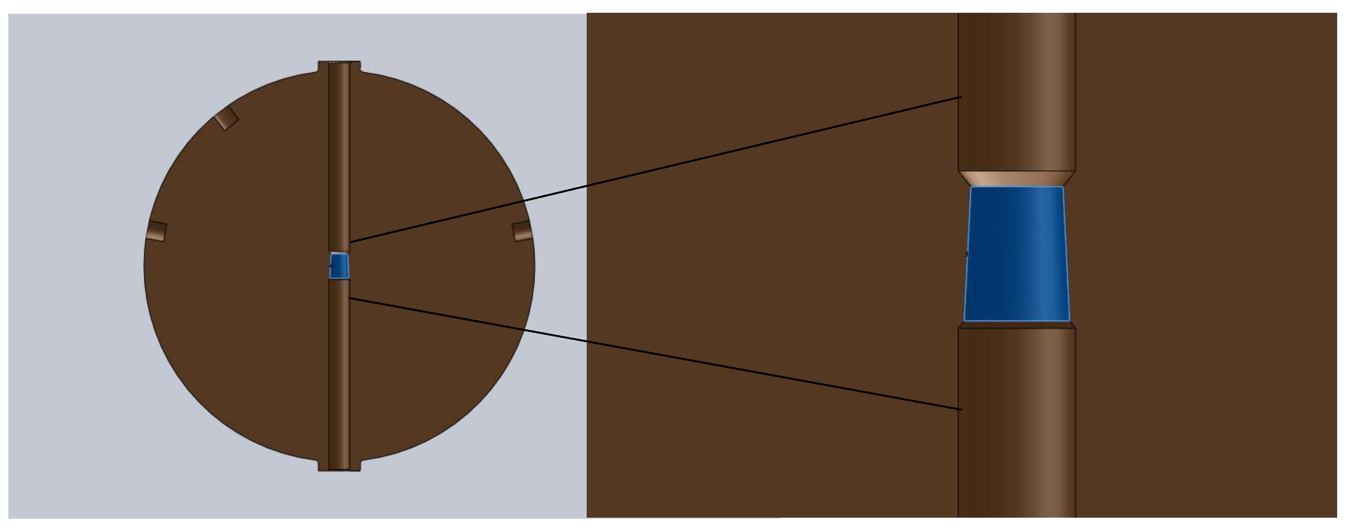
Figure 5.
Results of the simulations showing the surfaces where the displacements have the same magnitude (iso-displacements). The final result is the sphere dropping 0.8977 micrometers. Source: The authors.
Figure 5.
Results of the simulations showing the surfaces where the displacements have the same magnitude (iso-displacements). The final result is the sphere dropping 0.8977 micrometers. Source: The authors.
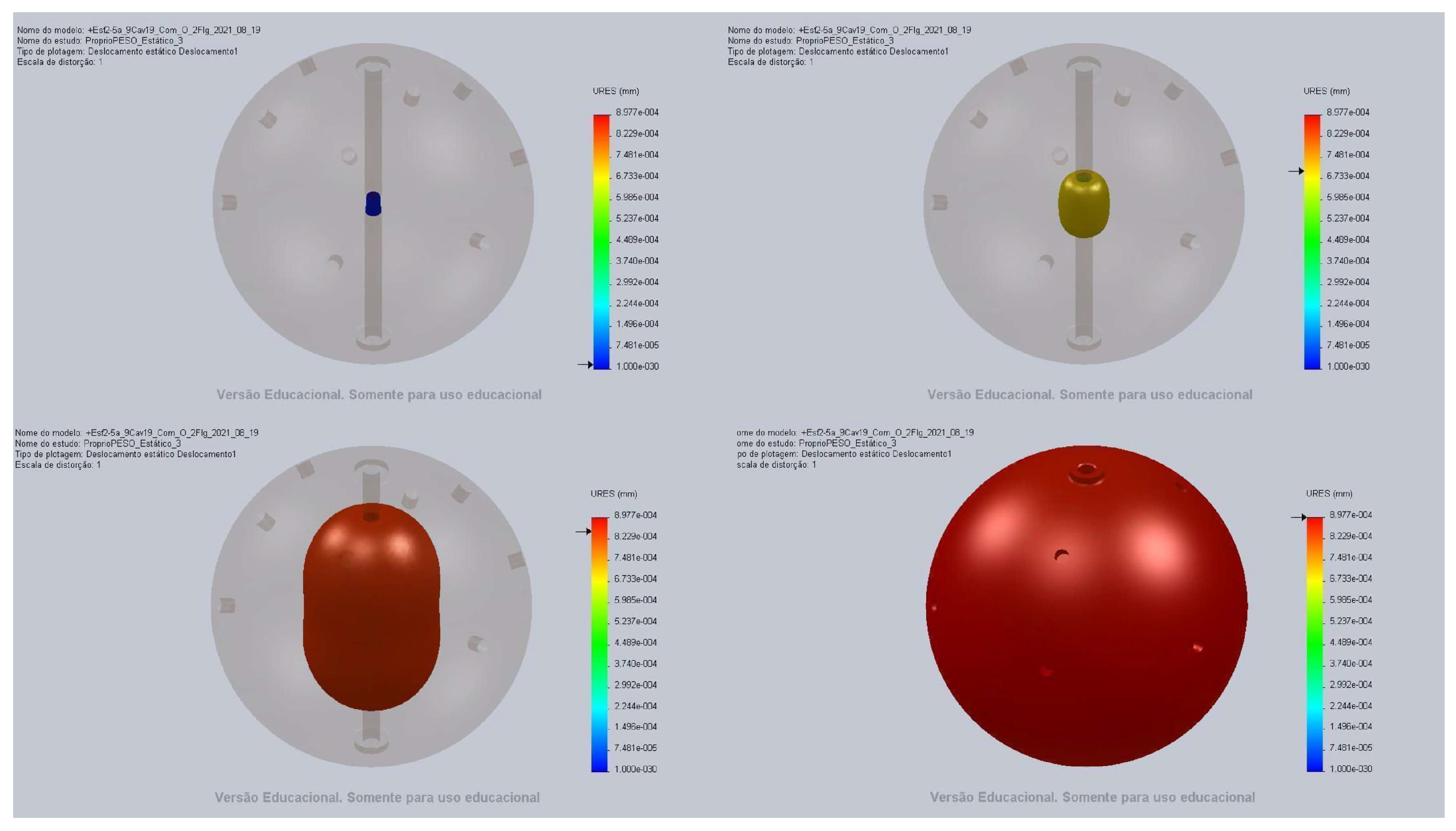
Figure 6.
Ingot from which the sphere was machined. Courtesy of Odylio D. Aguiar.
Figure 7.
Representation of the possible internal microstructure of the ingot and the region where the sphere was machined from. Source: Adapted by the authors from the free Internet image in <https://artpictures.club/autumn-2023.html>; access on June 21, 2025.
Figure 7.
Representation of the possible internal microstructure of the ingot and the region where the sphere was machined from. Source: Adapted by the authors from the free Internet image in <https://artpictures.club/autumn-2023.html>; access on June 21, 2025.
Figure 8.
Graphic of the Brinell hardness of CuAl as a function of the cooling speed. Source: [35].
Figure 8.
Graphic of the Brinell hardness of CuAl as a function of the cooling speed. Source: [35].
Figure 9.
Drawing of the antenna’s model that was simulated, showing its 2 parts. The spherical, external part was considered harder than the internal, cylindrical part by 20%. Source: The authors.
Figure 9.
Drawing of the antenna’s model that was simulated, showing its 2 parts. The spherical, external part was considered harder than the internal, cylindrical part by 20%. Source: The authors.
Figure 10.
For the Sphere I case (with intermediate bottom width of the external part and 20% difference in the Young modulus) these are the mode shapes with their respective frequencies and a bandwidth of 52.5 Hz. Source: The authors.
Figure 10.
For the Sphere I case (with intermediate bottom width of the external part and 20% difference in the Young modulus) these are the mode shapes with their respective frequencies and a bandwidth of 52.5 Hz. Source: The authors.
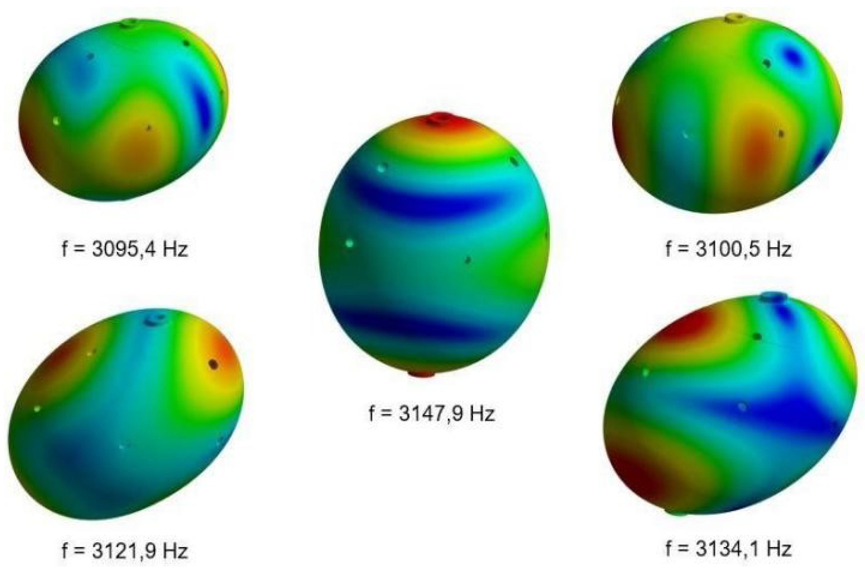
Figure 11.
For the Sphere II case (with largest bottom width of the external part and 30% difference in the Young modulus) these are the mode shapes with their respective frequencies and a bandwidth of 57.6 Hz. Source: The authors.
Figure 11.
For the Sphere II case (with largest bottom width of the external part and 30% difference in the Young modulus) these are the mode shapes with their respective frequencies and a bandwidth of 57.6 Hz. Source: The authors.
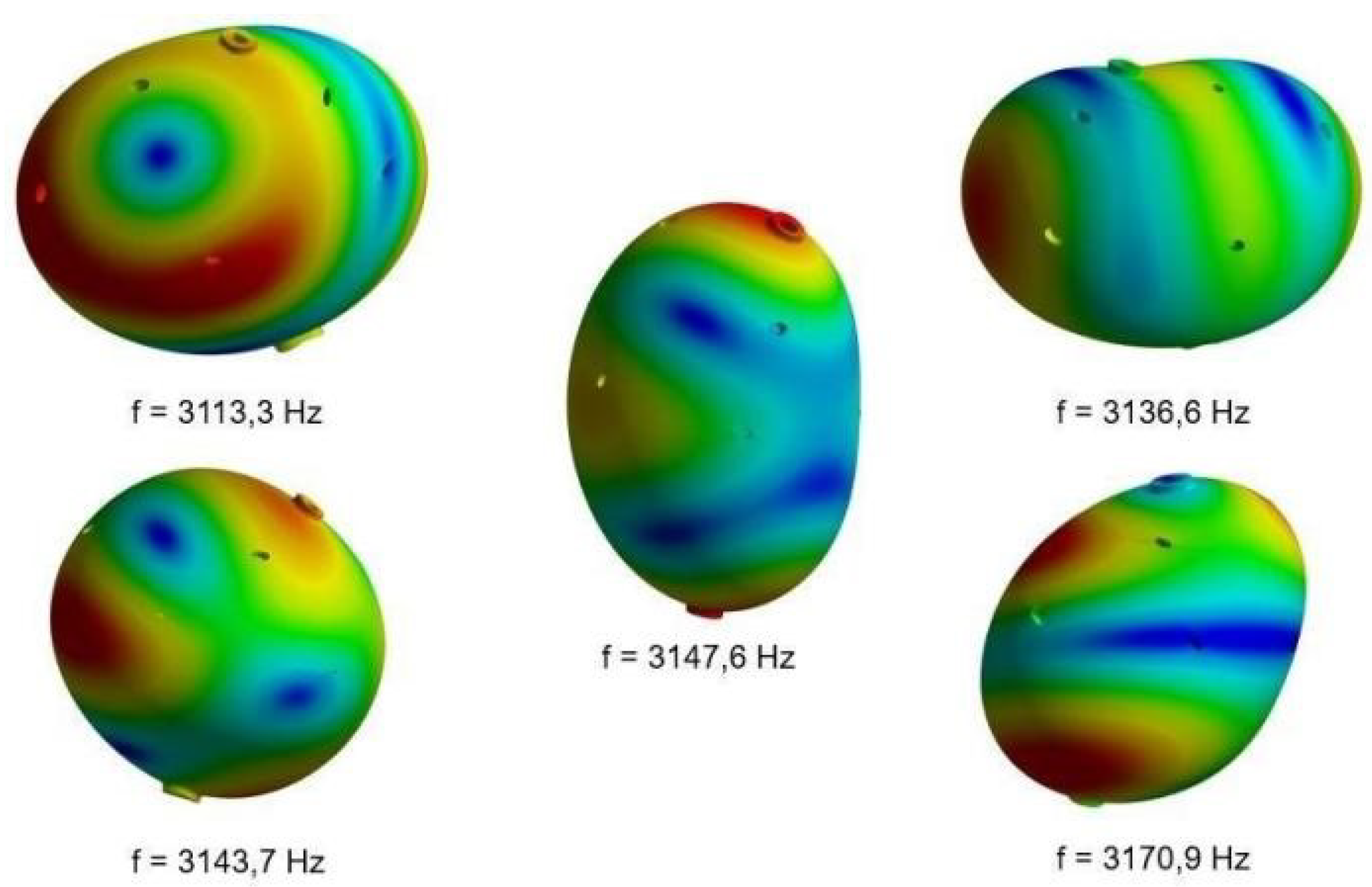
Figure 12.
For the Sphere III case (with narrowest bottom width of the external part and 20% difference in the Young modulus) these are the mode shapes with their respective frequencies and a bandwidth of 63.2 Hz. Source: The authors.
Figure 12.
For the Sphere III case (with narrowest bottom width of the external part and 20% difference in the Young modulus) these are the mode shapes with their respective frequencies and a bandwidth of 63.2 Hz. Source: The authors.
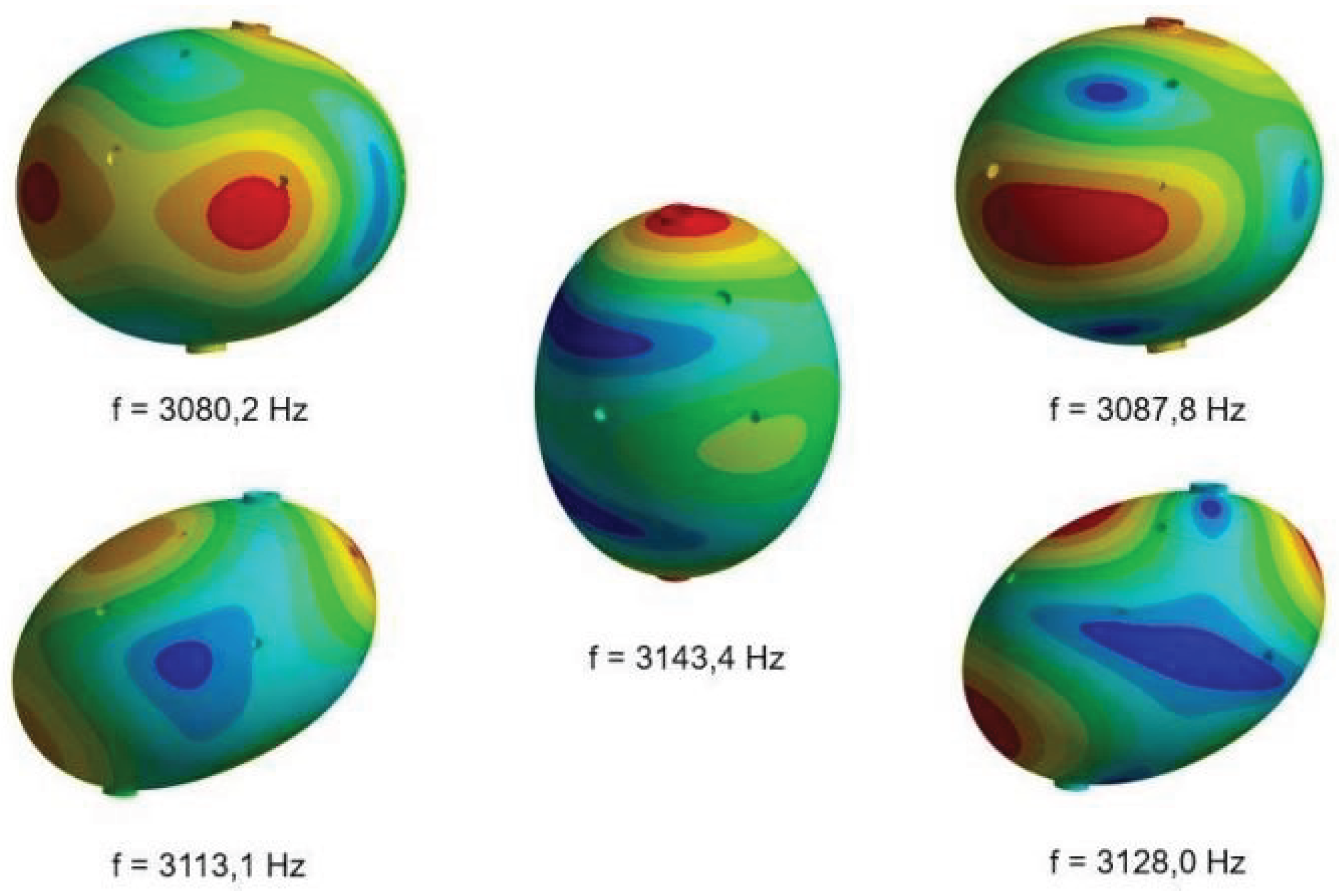
Table 2.
The first column displays the frequencies obtained experimentally with the detector cooled down to 5K; the second column displays the frequencies obtained by simulation without gravity; the third column shows the simulated frequencies considering the effect of gravity; and in the fourth column a twist of 5 degrees in the direction of gravity was assumed in the simulation to include some misalignment.
| Experimental Frequency | Frequencies | Frequencies (Gravity) |
Frequency (Gravity and twist) |
|---|---|---|---|
| 3,172.5 Hz [16] | 3,173.6 Hz | 3,183.2 Hz | 3,183.2 Hz |
| 3,183.0 Hz [16] | 3,173.7 Hz | 3,183.3 Hz | 3,183.3 Hz |
| 3,213.6 Hz [16] | 3,193.4 Hz | 3,200.3 Hz | 3,200.3 Hz |
| 3,222.0 Hz [16] | 3,193.4 Hz | 3,200.4 Hz | 3,200.4 Hz |
| 3,240.0 Hz [16] | 3,208.6 Hz | 3,212.4 Hz | 3,212.4 Hz |
| Band 67.5 Hz | Band 35.0 Hz | Band 29.2 Hz | Band 29.2 Hz |
Table 3.
For the model displayed in Figure 9 this table presents the 3 cases simulated, called Sphere I, Sphere II and Sphere III. The dimensions shown in columns 2 and 3 refer to the diameter of the internal part and the bottom thickness of the external part of the model that were assumed in each case.
| Internal part’s diameter (mm) | Bottom thickness (mm) | |
|---|---|---|
| Sphere I | 325 | 162.5 |
| Sphere II | 325 | 200 |
| Sphere III | 325 | 100 |
Table 4.
For the model displayed in Figure 9 this table presents the 3 cases simulated (Sphere I, Sphere II and Sphere III). The letter E represents the Young modulus for the material in each part of the model, shown in columns 2 and 3. Column 4 shows the approximate variations of E relative to the Young modulus of the antenna (128.621 GPa, see Table 1); the plus sign refers to the external part and the minus signal refers to the internal one.
| E of the external part (GPa) | E of internal part (GPa) | Variation (%) | |
| Sphere I | 143 | 117 | |
| Sphere II | 149 | 110 | |
| Sphere III | 143 | 117 |
Disclaimer/Publisher’s Note: The statements, opinions and data contained in all publications are solely those of the individual author(s) and contributor(s) and not of MDPI and/or the editor(s). MDPI and/or the editor(s) disclaim responsibility for any injury to people or property resulting from any ideas, methods, instructions or products referred to in the content. |
© 2025 by the authors. Licensee MDPI, Basel, Switzerland. This article is an open access article distributed under the terms and conditions of the Creative Commons Attribution (CC BY) license (http://creativecommons.org/licenses/by/4.0/).
Copyright: This open access article is published under a Creative Commons CC BY 4.0 license, which permit the free download, distribution, and reuse, provided that the author and preprint are cited in any reuse.


