
Submitted:
28 July 2025
Posted:
29 July 2025
You are already at the latest version
Abstract
Currently, robots are widely used in orthopedics for surgical operations in the world. The use of robots in orthopedics has increased the accuracy of bone cutting and im-plant placement, which has improved the results of surgical operations. Most robots used in orthopedics have a serial or parallel structural scheme. However, serial robots have low load capacity and rigidity and insufficient accuracy. The disadvantages of the parallel structural scheme of the robot are a smaller workspace and the presence of singular configurations compared to serial ones. To eliminate the above disadvantages of surgical robots for knee joint operations and to create an inexpensive robot, a hybrid Cartesian robot for knee joint surgery has been developed. The hybrid Cartesian robot has the strengths of parallel and serial robots, potentially smoothing out the main dis-advantages of their designs. The forward and reverse kinematics of the proposed robot are analyzed. A 3D model of a hybrid Cartesian robot for knee joint surgery is devel-oped and its prototype is designed in a simplified form based on it. The simplified pro-totype of a hybrid Cartesian robot for knee joint surgery provides sufficient accuracy in resection of hard bone and has good prospects for practical use.
Keywords:
orthopedic surgery
; robot
; hybrid Cartesian robot
; end effector
; cutter
; prototype
1. Introduction
Currently, thanks to the development of robotics, robotic systems are widely used in orthopedics. Robotic systems in orthopedics have shown improved surgical results due to increased accuracy of bone cutting and implant placement, and reduced surgery time [1,2,3]. Robotic systems (RS) are divided into three systems: autonomous, manual, and remote-controlled [4]. Autonomous RS means that the robot can perform the operation completely independently, while the surgeon can only interrupt it with an emergency stop [5]. Manual RS is equivalent to semi-autonomous RS in orthopedic surgery. Here, the surgeon and the robot jointly move the surgical instrument mounted on the robot's end effector [4]. Remote-controlled RS is a standard telecontrol system of two robots, master-slave.
Manual (semi-autonomous) RS, in contrast to autonomous RS, are more common among surgeons due to the possibility of full control of the operation. The robot included in the RS in all configurations ensures control over the movement of the instrument using speed and force tracking schemes, ensuring patient safety. The force exerted by the robot's end effector on the patient's bone is adequately tactilely transmitted to the surgeon's hand. The robot fixes the instrument in the planned position in the event of a program failure or loss of power source. When the robot's end effector moves, it automatically avoids collisions with surrounding objects. The robot's end effector and all its links, drives are in a controlled sterile environment.
Robotic systems developed for orthopedics in recent decades perform mainly cutting, positioning and aligning of bones, with a tendency to increase precision. The use of autonomous RS is still limited due to concerns about the safety of operations associated with autonomous operation. When the procedure is stopped, which occurs during bone cutting, re-registration is required, which can lead to interruption of the operation. Manual RS are most convenient for surgeons due to the ability to control the robot and interrupt the operation at any time, and then continue without significant problems. Manual RS currently provide maximum patient safety.
A critical unique feature of the design of manual RS in orthopedics is that they must be able to handle high forces due to the high rigidity of bone. The main advantages of manual RS used in orthopedics include increased precision and accuracy of implant positioning, improved reproducibility, improved implant stability and less pain. The main disadvantages of manual RS include safety issues, high economic costs and long operating times.
Manual RS widely used in surgery:
- ACROBOT is a semi-autonomous robot for unilateral knee arthroplasty. ACROBOT was developed for knee joint surgery [6]. It uses active constraint control, which limits the robot's movement within a specified working area, and the surgeon can safely cut the bone with high precision;
- RS RIO is an interactive orthopedic robotic arm developed by MAKO Surgical Corp., Fort Lauderdale, Florida, USA [7]. RS RIO has tactile and auditory feedback, a force-controlled tip, and an in-circuit surgeon;
- RS Navio PFS is a computer-aided orthopedic navigation and surgical drilling system, and a semi-autonomous, manual and image-free system [8,9,10];
- RS MAKO is an image-based system with tactile and auditory feedback [11]. RS MAKO is a human-robot interaction system using user input and robotic control, and an emergency automatic shutdown as a safety strategy;
The development of new manual RS for minimally invasive orthopedic surgeries has great potential [12,13]. The main problem with most of the existing semi-autonomous RS is that they take up a lot of space in the operating room and are relatively expensive. Mostly, semi-autonomous RS are serial type robots with a large workspace relative to the task. The serial robot consists of a single kinematic chain of links and joints connected in series from the base to the actuator, and have relatively low rigidity and accuracy, and have a low nominal load-to-weight ratio. To overcome the above disadvantages of semi-autonomous RS, several small bone-anchored surgical robots have been developed. In [14], a mini bone-anchored robotic system (MBARS) was developed for knee arthroplasty. This hexapod robot is rigidly attached directly to the bone. The robot scans the femur shape directly, eliminating the need for preoperative imaging or intraoperative bone registration and tracking. The disadvantages of the MBARS RM are its large weight, small workspace, and lack of normal surgeon access to the surgical field. In [15], a lighter robot HyBAR with a parallel structure was created. In the HyBAR robot, it was possible to move most of the mechanism from under the cutting instrument, thereby increasing the surgeon's access to the surgical field.
The advantages of the parallel structure for surgical robots are undeniable and allow maintaining rigidity against significant reaction forces from high-speed bone cutting. In addition, the known disadvantages of the parallel structure are mainly based on the typical hexapod robot. To eliminate these disadvantages of the parallel structure, robots for knee joint surgery based on a Cartesian parallel robot were developed in [16,17], which eliminated some of the disadvantages of the hexapod in terms of safety, cutting accuracy, kinematics and control. Although Cartesian parallel robots have a less simple structure compared to the hexapod, the cross-linkage between the links also makes its kinematics and dynamics more complex than in a serial robot. It is difficult to derive an analytical solution for the workspace of a parallel manipulator in terms of the geometric parameters of the links. Therefore, it is difficult to know what the exact workspace is for certain designed link parameters. A special problem is the detection of special points (singularities) in Cartesian parallel robots.
To eliminate the above disadvantages of surgical robots for knee joint operations and to create a low-cost robot, a hybrid Cartesian robot for knee joint surgery is developed.
2. Materials and Methods
2.1. Structure of 6-DoF Hybrid Cartesian Robot
To develop a hybrid Cartesian robot, we use a combination of a Cartesian manipulator with three degrees of freedom and a serial manipulator with three degrees of freedom. In this structural diagram, the Cartesian manipulator provides accurate and effective positioning of the end effector, and the serial manipulator provides flexibility in the orientation of the end effector. The hybrid Cartesian robot has the following structural scheme 3P3R (3 prismatic and 3 revolute joints), shown in Figure 1. There are three linear links 1,2,3 and three rotary links 4,5,6, which are mounted on a rectangular frame 0. The end effector 7 is rigidly attached to link 6.
Figure 1.
Structural scheme of the 6-DoF hybrid Cartesian robot.
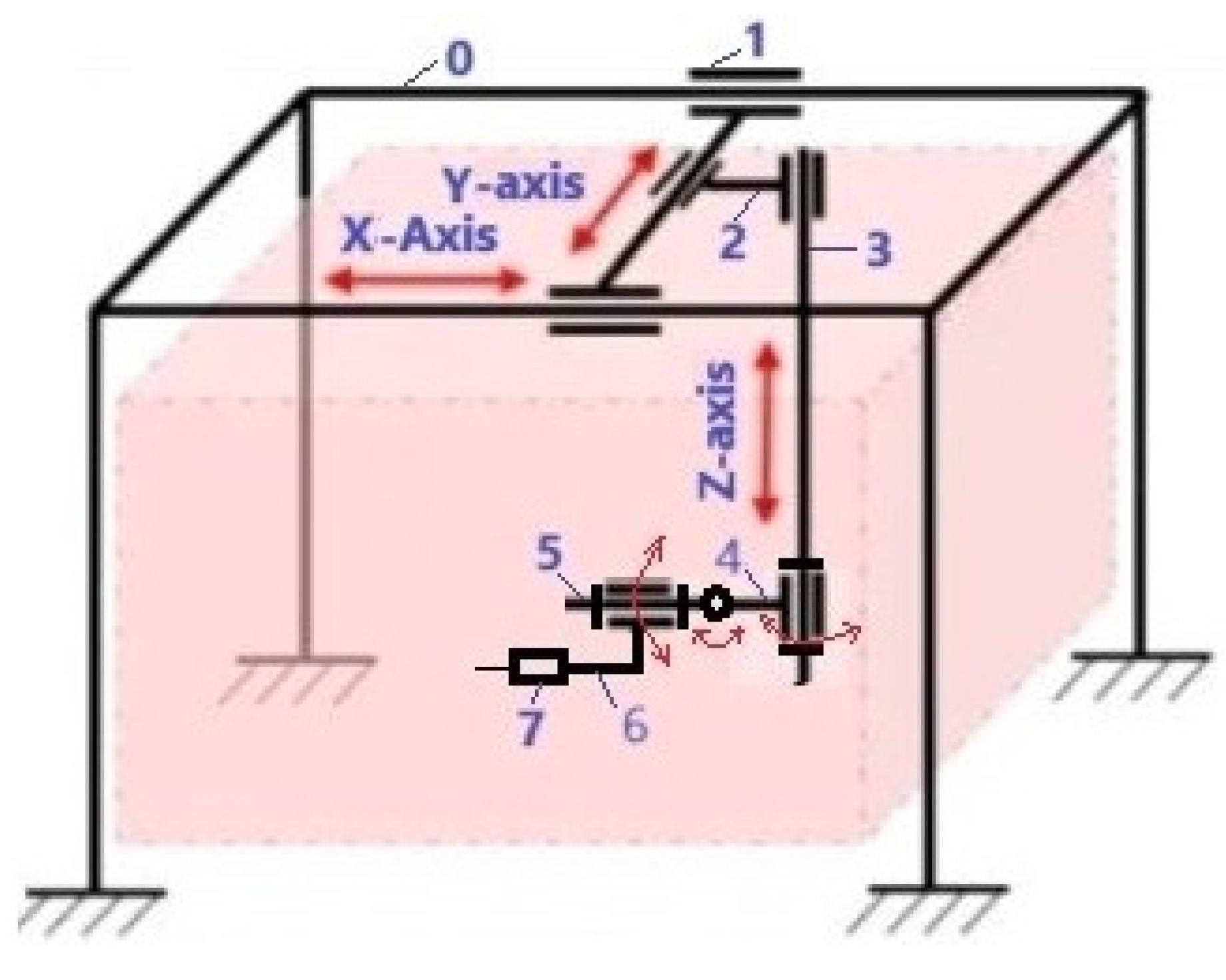
The hybrid Cartesian robot has six degrees of freedom (6-DoF). The first three links are designed for linear movement of the end effector along the X, Y and Z axes, and three rotational links are needed to adjust the orientation of the end effector. The end effector of the robot 7 is an orthopedic multifunctional drill, with a force sensor and a 6-axis force sensor built into the handle, which are assembled as a single module.
2.2. Kinematic Analysis of 6-DoF Hybrid Cartesian Robot
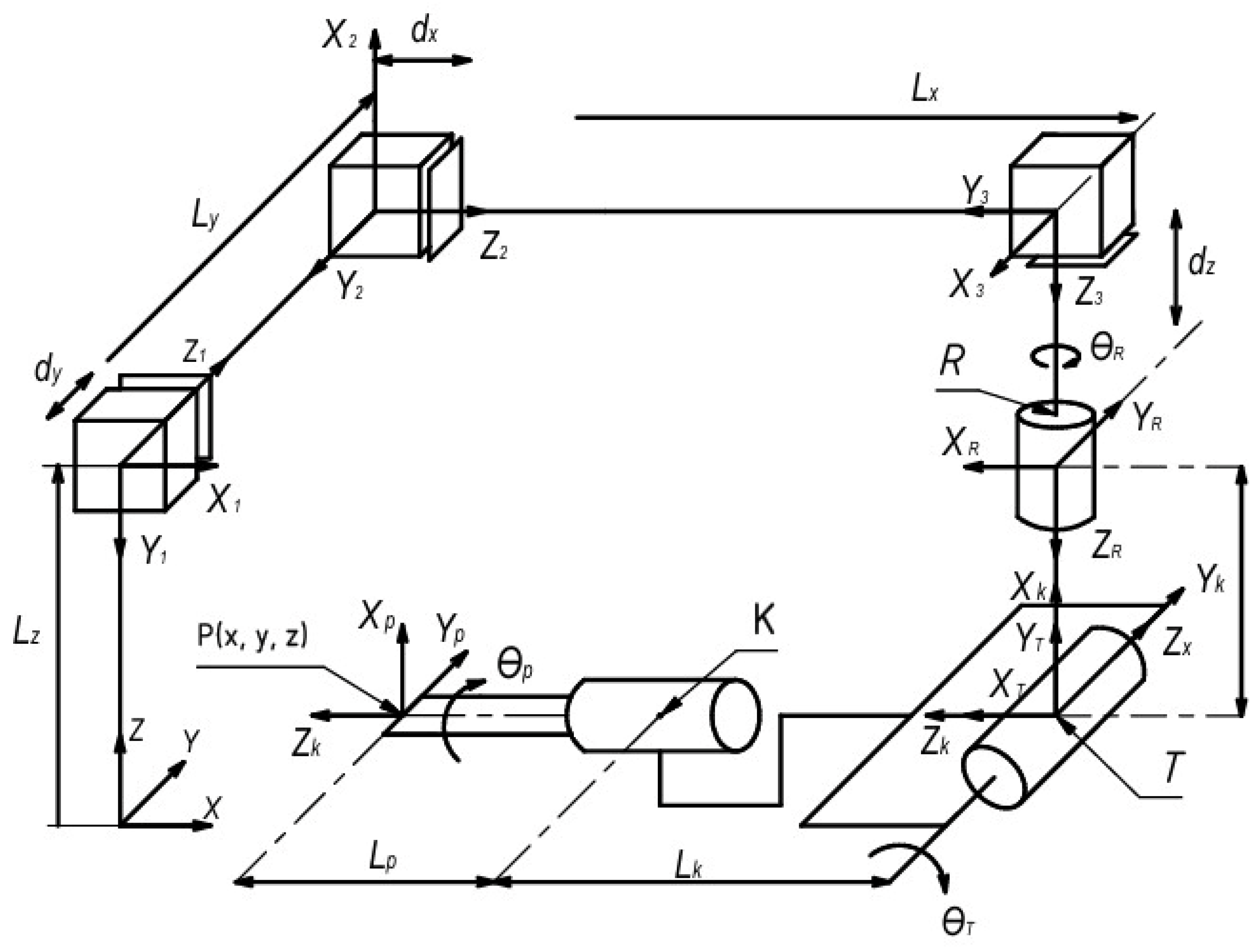
The hybrid Cartesian robot has six degrees of freedom (6-DoF) and can perform 3 translational linear motions and three rotational motions of the end effector. The kinematic diagram of the 6-DoF hybrid Cartesian robot is shown in Figure 2. The following notations are introduced:
are the initial lengths of the robot's linear links along the X, Y, Z axes, respectively;
are the movements of the carriages of the linear guides of the X, Y, and Z axes due to the robot's drives;
x, y, z are the coordinates of the position of the point P of end effector in the XYZ coordinate system;
R is the rotational link that rotates by an angle of about the Z axis;
T is the rotational link attached perpendicularly to the R link, which tilts the end effector by an angle of about the Y axis;
K is a rotary link attached perpendicularly to the T link, which tilts the end effector by an angle of around the X axis;
The R, T and K rotary links allow the end effector to be precisely oriented during bone cutting by entering the values of the angles , , .
is the distance from the center of the R link to the center of the T link.
is the distance from the center of the T link to the center of the K link.
is the distance from the center of the K link to the tip of the end effector at point P.
Figure 2.
Kinematic scheme of a 6-DoF hybrid Cartesian robot.
To solve the forward and reverse kinematic analysis of a hybrid Cartesian robot, we use the Denavit-Hartenberg matrix method. It is known that the position and orientation of a rigid body in space is uniquely determined by six coordinates: three linear (Cartesian) and three angular (Euler angles). Using the method proposed in 1955 by scientists Jacques Denavit and Richard Hartenberg, this number can be reduced to four parameters, called the Denavit-Hartenberg parameters. This simplification is achieved using a standardized algorithm for binding coordinate systems to robot links. According to the Denavit-Hartenberg method, solving a direct kinematics problem consists of the following stages: binding coordinate systems to robot links, determining the Denavit-Hartenberg parameters, and constructing homogeneous transformation matrices.
The Denavit–Hartenberg parameters consist of a set of four parameters for each joint of the 6-DOF robot and serve to define the geometry and spatial relationships between successive links in the robot, is a transformation matrix representing the current state (i) from the previous state (i − 1).
Here,
is the rotation matrix, the link rotation by angle around the Z axis;
is the translation matrix, the link displacement along the Z axis;
is the rotation matrix, the link rotation angle around the X axis;
is the translation matrix, the length of the link along the X axis;
The Denavit-Hartenberg parameters for the 6-DoF Cartesian hybrid robot are shown in Table 1.

Table 1.
Denavit-Hartenberg parameters for the 6-DoF Cartesian hybrid robot.
| Link i | Link length |
Link offset |
Link angle |
Link angle |
|---|---|---|---|---|
| 1 | 0 | |||
| 2 | 0 | |||
| 3 | 0 | |||
| R | 0 | |||
| T | 0 | |||
| K | 0 | 0 | ||
| P | 0 |
Let's perform a direct kinematic analysis of a hybrid Cartesian robot. Direct kinematic analysis is necessary to model the motion of a hybrid Cartesian robot for given control system parameters. Here we will use a homogeneous transformation matrix to organize fixed and variable elements, describing the relationship between coordinate systems.
Equations (1–5) represent the homogeneous transformation matrix for the three prismatic joints, their position and orientation. We denote
then the transformation matrices of the axes R, T, K look like this
The position of the end effector is determined by the full transformation matrix
The resulting full transformation matrix (8) is used to determine the position and orientation of the end effector. The position of the end effector is represented by the last column of the full transformation matrix, and the orientation is represented by the first three columns of the matrix.
The position of the point P(x,y,z) of end effector is represented by its coordinates x, y, z and is determined from equation (9), which are functions of – the movements of the carriages of the linear guides of the axes X, Y and Z and the angles , , - they are set depending on the required orientation of the working tool for cutting bone.
The solution of the inverse kinematic problem is necessary to determine the parameters of the control system of a hybrid Cartesian robot. Unlike direct kinematics, inverse kinematics it is necessary to determine the linear movements of the links , for given coordinates x, y, z of the position of the point P of end effector , and angles , , - the orientation of the working tool for cutting bone (see Figure 2). From equations (9) it is easy to determine
Equations (10) allow us to determine the laws of motion of servomotors that perform linear movements of links , which provide the required trajectory of the end effector of a hybrid Cartesian robot.
2.3. 3D Model of a 6-DOF Hybrid Cartesian Robot
Designing a 6-DOF hybrid Cartesian robot requires taking into account several factors to ensure normal operation, reliability and safety. These factors include:
- requirements for the rigidity of the robot structure to reduce deformation under load, which increases the accuracy of the end effector;
- ensuring smooth and controlled movement of the end effector, minimizing vibrations and ensuring accuracy.
- the ability to effectively reproduce specified trajectories of the end effector.
- the ability of the robot to operate stably with the maximum weight of the end effector.
- the choice of materials for the manufacture of the robot taking into account strength, durability and the possibility of sterilization.
- it is necessary to select servomotors to ensure smooth and accurate movement of the end effector with a given mass.
To develop a 3D model of a hybrid Cartesian robot that has greater rigidity and accuracy of positioning of the end effector during knee joint surgery, we adopted the following dimensions of the rectangular frame: length 1500 mm, width 600 mm, height 1600 mm. The payload on the end effector is no more than 10 kg. The range and speed of change of angles and movements of the end effector are given in Table 2.
Table 2.
Range and speed of change of angles and movements of the end effector.
| Angles and axes | Range | Speed |
|---|---|---|
| Angle around the X axis | ±900 | 450/s |
| Angle around the Y axis | ±900 | 450/s |
| Angle around the Z axis | ±1800 | 450/s |
| X-axis | 400 mm | 100 mm/s |
| Y-axis | 400 mm | 100 mm/s |
| Z-axis | 400 mm | 50 mm/s |
The basis of this robot is a Cartesian manipulator responsible for precise linear movement in the X, Y and Z directions. This manipulator consists of:
- a rectangular fixed frame made of 80x80 structural aluminum profiles;
- servomotors with drivers: for linear movement;
- linear guides with a ball screw transmission for converting the rotational movement of servomotors into linear movement.
The three-axis Cartesian manipulator provides highly accurate and repeatable movements, which is very important for knee joint surgery. The parameters of the corresponding servomotors, linear guides with a ball screw transmission for converting the rotational movement of servomotors into linear movement are selected by us in order to ensure precise linear movements, with a given speed of the end effector.
The serial manipulator with three degrees of freedom has flexible control to provide angular orientation in workspace of the end effector, which makes it ideal for knee joint surgery. The end effector can move smoothly along the entire range of motion, providing the required angular orientation. The serial manipulator achieves its flexibility due to the 3R-joint, which includes three rotary drives that provide both rotation around the Z-axis and tilts of the end effector around the X and Y axes. Located at an angle of 90 degrees, the Z and X, Y axes drives provide the necessary required movements. The axis of the 3R rotary joint, running parallel to the Z-axis, is fixed at the base of its linear guide. Each rotary drive uses motors paired with gearbox systems with brakes for high-precision angular holding of the end effector in workspace.
Figure 3 shows a 3D model of a hybrid Cartesian robot for knee joint surgery. The following notations are used: 1-frame, 2-servomotors, 3-profile guide of the X-axis, 4-profile guide of the Y-axis, 5-profile guide of the Z-axis, 6-rotary link with a servomotor for rotating the working element around the Z-axis, 7-rotary link with a servomotor for rotating the end effector around the Y-axis, 8-rotary link with a servomotor for rotating the end effector around the X-axis, 9- end effector in the form of an orthopedic saw, 10-patient's knee joint, 11-operating table.
Figure 3.
3D model of the hybrid Cartesian robot for knee surgery.
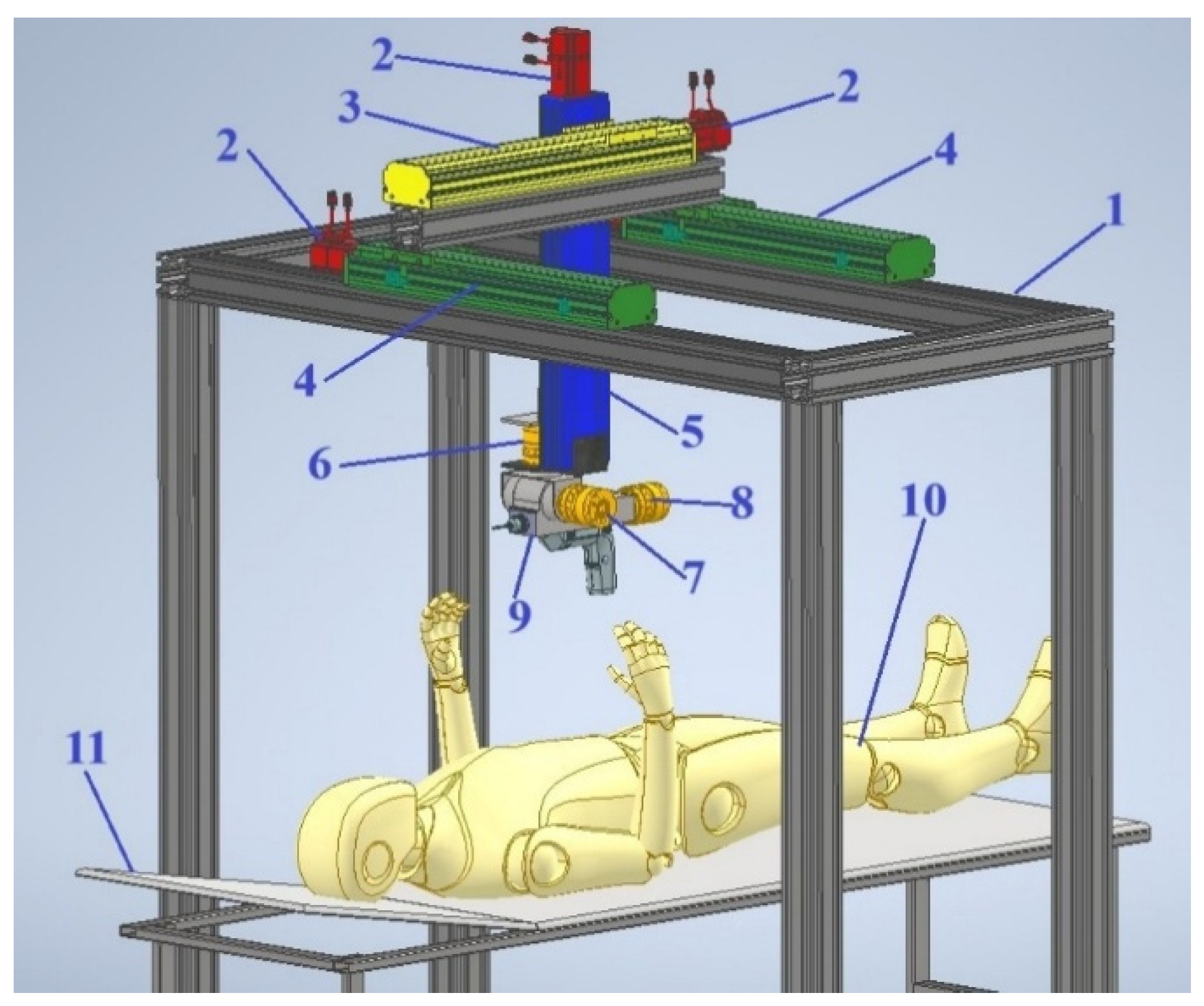
Figure 4 shows a top view of the 3D model of the hybrid Cartesian robot for knee surgery.
Figure 4.
Top view of the 3D model of the hybrid Cartesian robot for knee surgery.
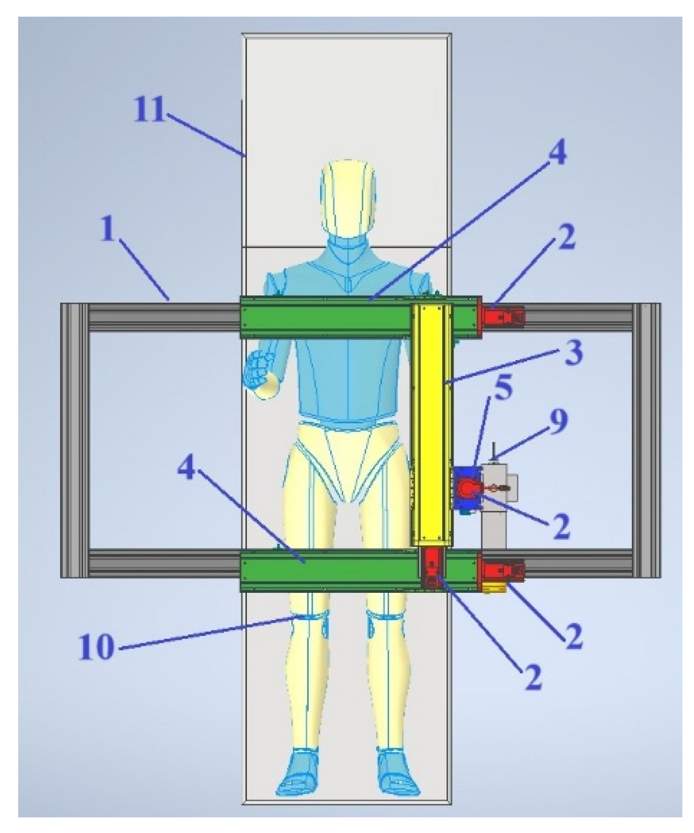
Figure 5 shows the front view of the 3D model of the hybrid Cartesian robot for knee surgery.
Figure 5.
Front view of the 3D model of the hybrid Cartesian robot for knee surgery.
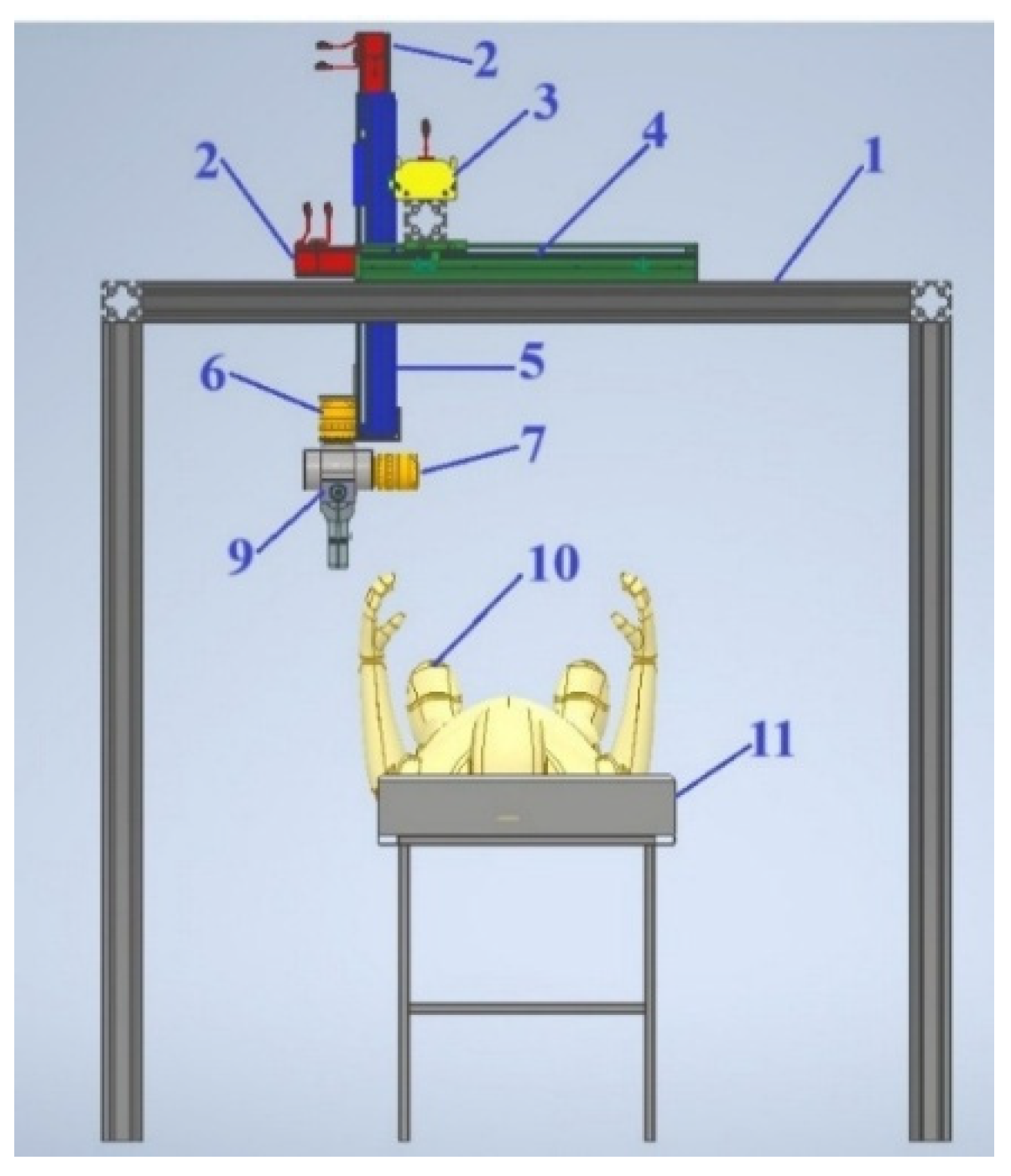
Figure 6 shows the side view of the 3D model of the hybrid Cartesian robot for knee surgery.
Figure 6.
Side view of a 3D model of a hybrid Cartesian robot for knee surgery.
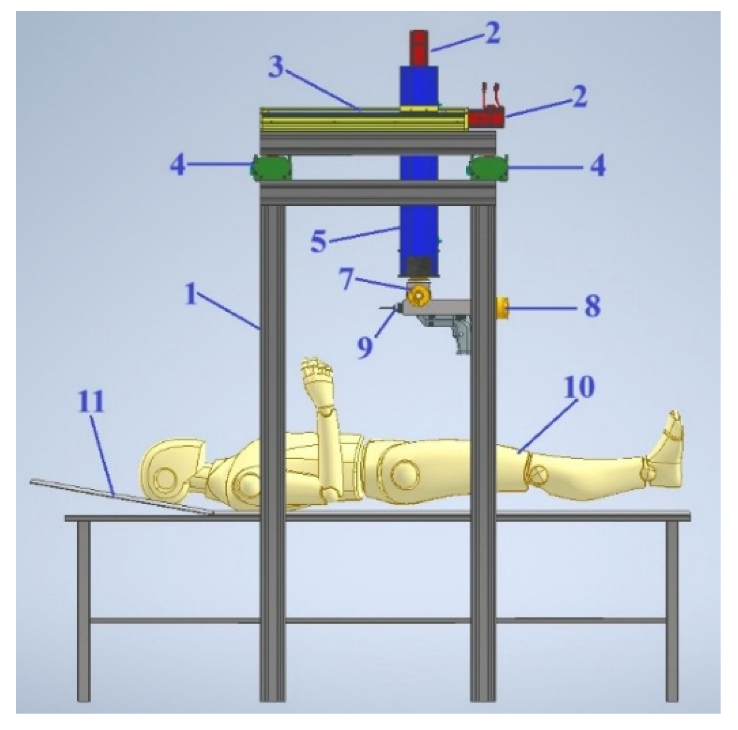
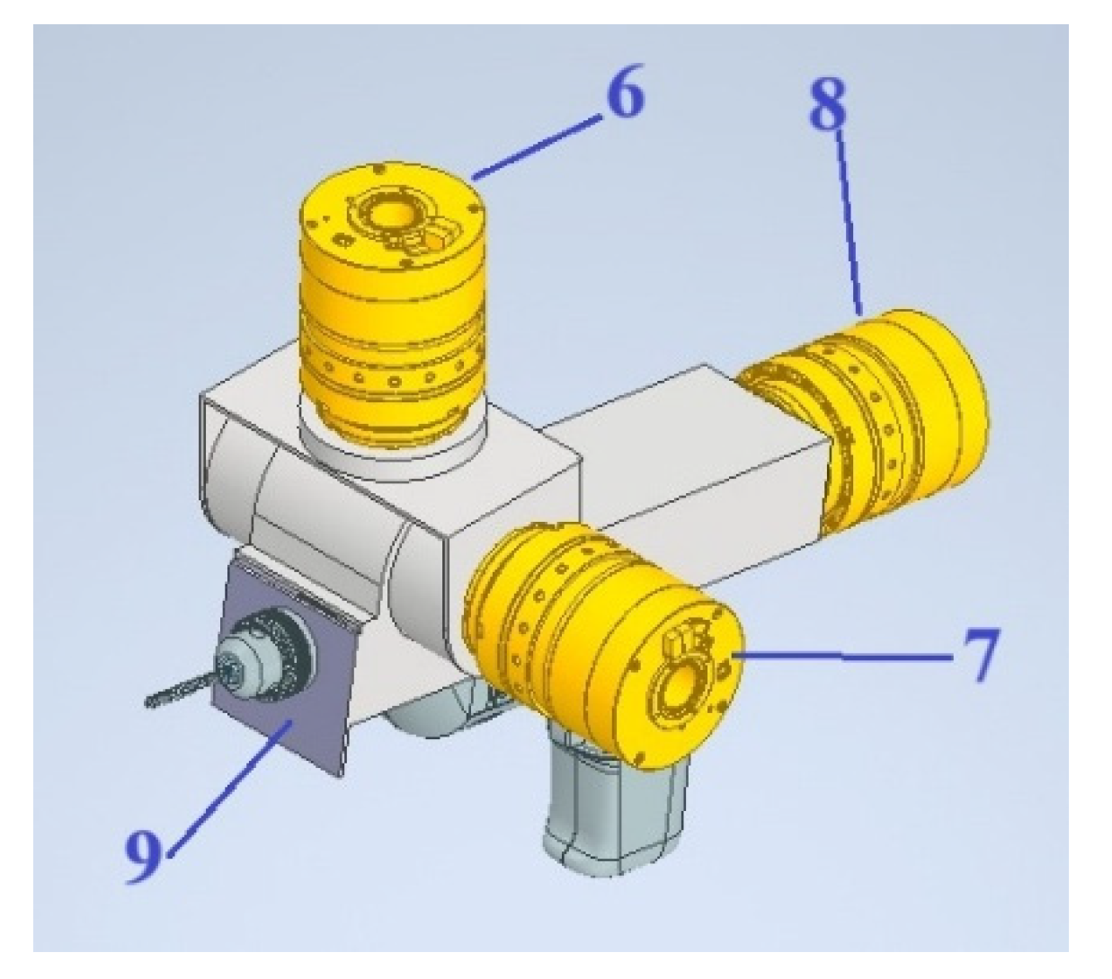
Figure 7 shows a view of a 3D model of an assembly of three rotary links with servomotors with a end effector in the form of an orthopedic saw
Figure 7.
View of a 3D model of an assembly of three rotary links with servomotors with a end effector in the form of an orthopedic saw.
Figure 7.
View of a 3D model of an assembly of three rotary links with servomotors with a end effector in the form of an orthopedic saw.
The hybrid Cartesian robot for knee surgery works as follows (see Figure 3). In order to perform the operation of cutting the knee joint 10, the trajectory of movement of the end effector 9 is set in the computer. Control signals are sent from the computer to the drivers of three servomotors 2, and thus the end effector 9 performs three translational linear movements along the axes X, Y, Z along the profile guides 3, 4, 5. Then, according to the control signals set from the computer, the angular orientation of the end effector 9 around the Z axis is performed using the rotary link with the servomotor 6, the angular orientation of the end effector 9 around the Y axis is performed using the rotary link with the servomotor 7, and the angular orientation of the end effector 9 around the X axis is performed using the rotary link with the servomotor 8. The coordinated operation of the drivers of the servomotors 2 and the servomotors of the rotary links 6, 7, 8 implements the specified trajectory of movement of the end effector 9, for cutting the knee joint 10, in the specified area.
3. Results
3.1. Prototype of Hybrid Cartesian Robot for Knee Joint Surgery
According to the 3D model of the hybrid Cartesian robot for knee joint surgery, we have developed a version of its simplified prototype. Here we consider that the orientation angles of the end effector are fixed, i.e., . With fixed orientation angles, we will consider only the movement of the end effector along the X, Y, Z axes. To assemble the simplified prototype of the hybrid Cartesian robot for knee joint surgery, the configuration of its system was developed. Figure 8 shows the configuration of the simplified prototype of the hybrid Cartesian robot for knee joint surgery. The following initial data are specified: the frame dimensions along the X axis are 700 mm, along the Y axis are 765 mm, and the height along the Z axis is 450 mm. The mass of the end effector is m=3.0 kg.
Figure 8.
Configuration of a simplified prototype of a hybrid Cartesian robot for knee joint surgery.
Figure 8.
Configuration of a simplified prototype of a hybrid Cartesian robot for knee joint surgery.
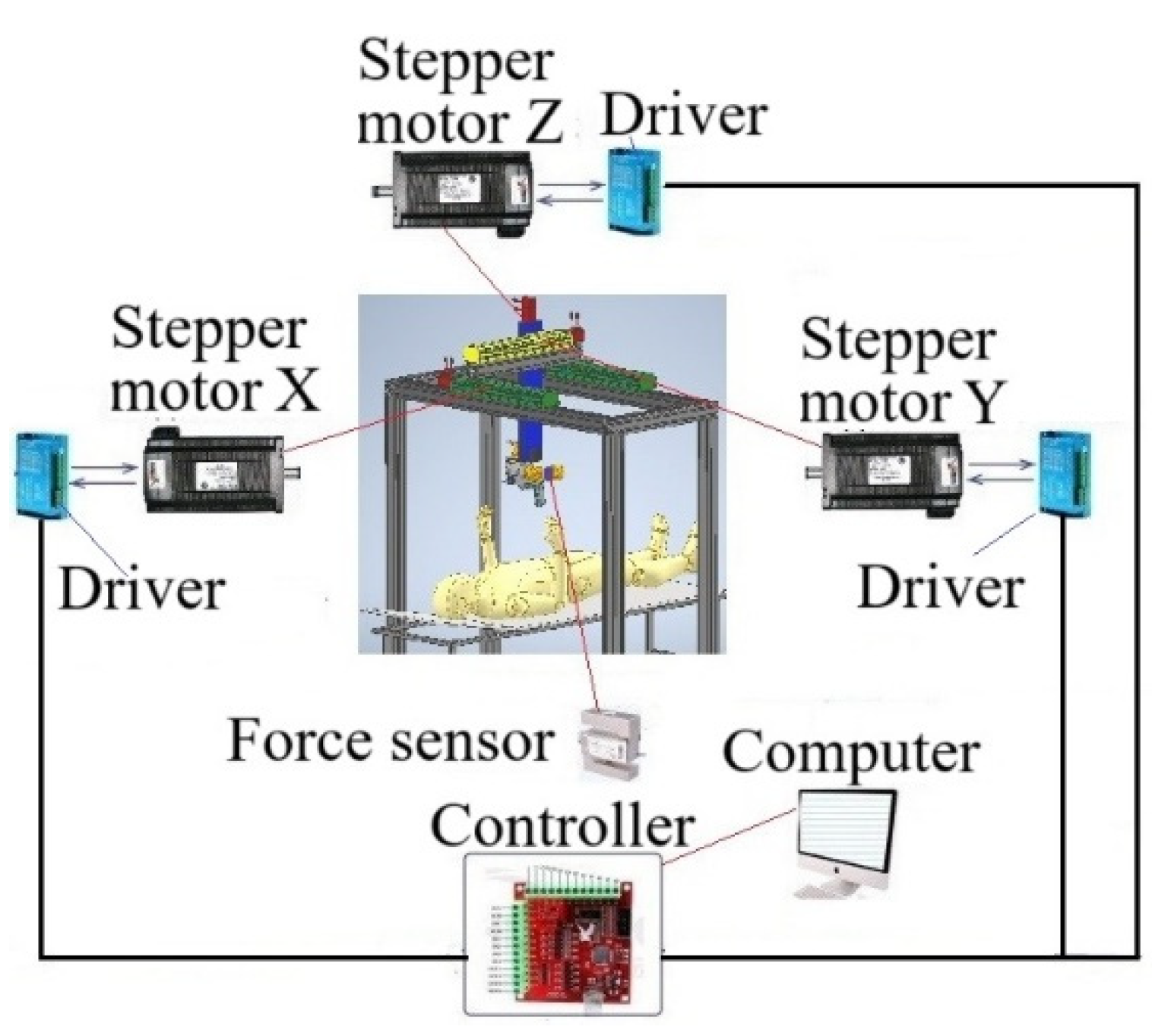
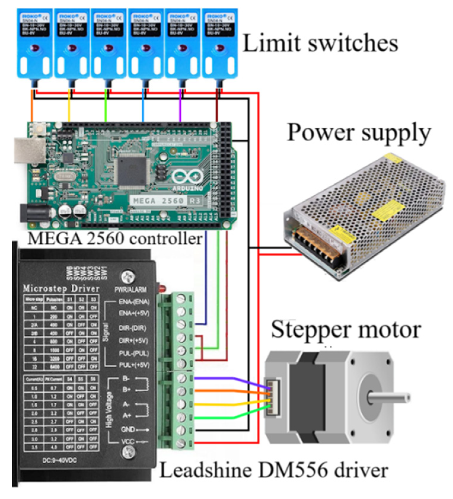
The drives of the simplified prototype of the hybrid Cartesian robot for knee joint surgery (Figure 8) consist of three Nema 23 stepper motors mounted on profile guides of the X, Y, Z axes. The stepper motors are equipped with Leadshine DM556 drivers, which are connected to the MEGA 2560 controller. The controller supports 3-axis control. Using the MEGA 2560 controller, the simplified prototype of the hybrid Cartesian robot for knee joint surgery is controlled by a computer via a USB port. Control signals are sent to the stepper motor drivers through the MEGA 2560 controller from the computer, and thus the end effector performs three translational linear movements along the X, Y, Z axes along the profile guides. A force sensor is connected to the end effector to determine its cutting force on bone. The force sensor is connected to the ZET 058 strain gauge station [18], which, together with the ZETLAB TENZO software, allows collecting information from the force sensor in real time.
Based on the developed configuration of the simplified prototype of the hybrid Cartesian robot for knee joint surgery, a prototype was manufactured, shown in Figure 9. The prototype frame is assembled from rectangular metal profiles measuring 40×40 mm. The drive system of the prototype of the Cartesian robot for knee joint surgery is based on ball screws (BSP), which provide high-precision linear movement along three coordinate axes. Two BSPs are installed on the X axis, which provide stable and synchronous movement of the end effector. And one BSP is located on the Y and Z axes. All BSPs are equipped with NEMA 23 stepper motors. These motors provide the required torque and positioning accuracy, while having compact dimensions. The stepper motor drivers, power supply and MEGA 2560 controller are housed in a control cabinet.
Figure 9.
Simplified prototype of a hybrid Cartesian robot for knee joint surgery.

Figure 10 shows the control circuit scheme of the simplified prototype of the hybrid Cartesian robot for knee joint surgery. The control program of the simplified prototype of the hybrid Cartesian robot for knee joint surgery was developed in the Arduino IDE environment [19].
Figure 10.
Wiring scheme of the control elements of the simplified prototype of a hybrid Cartesian robot for knee joint surgery.
Figure 10.
Wiring scheme of the control elements of the simplified prototype of a hybrid Cartesian robot for knee joint surgery.
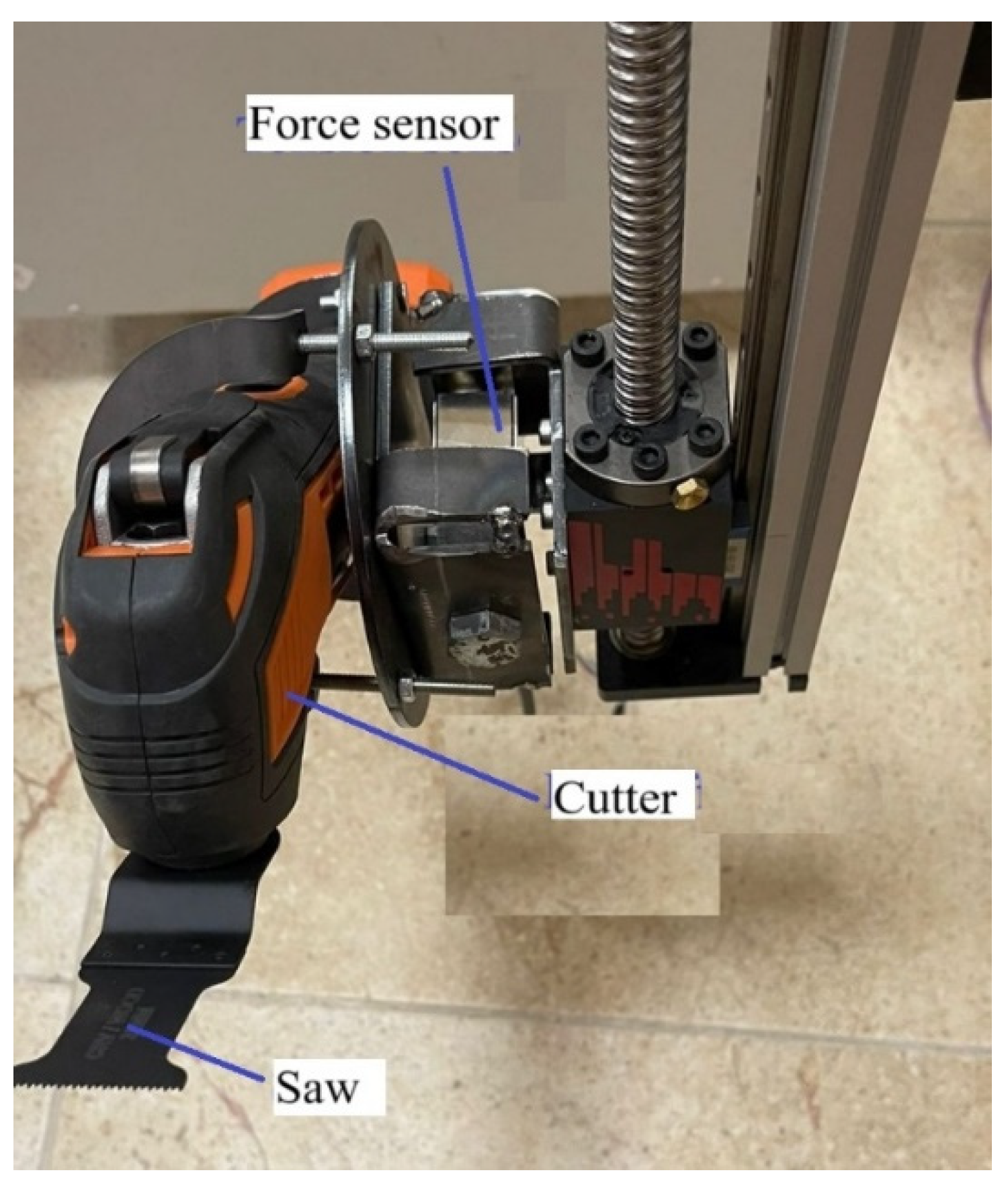
As a end effector for bone resection, a cutter from P.I.T. (China) [20] with the following parameters was selected: voltage 24V, input power 150W, oscillation rate 11000-21000 rpm, oscillation angle 3.5°. The cutter is equipped with a flat saw with a working cutting length of 40 mm and a cutting width of 34 mm. A cow knee joint bone was selected as an object for testing. The bone cutting force is measured by a CALT DYLY-103 force sensor built into the cutter mount. The force sensor is connected to a ZET 058 strain gauge station [18] and then to a computer. Using the ZETLAB software [18], it is possible to obtain oscillograms of the bone cutting force. Figure 11 shows a cutter with a force sensor for determining its bone cutting force.
Figure 11.
Cutter with force sensor.
3.2. Experimental Results
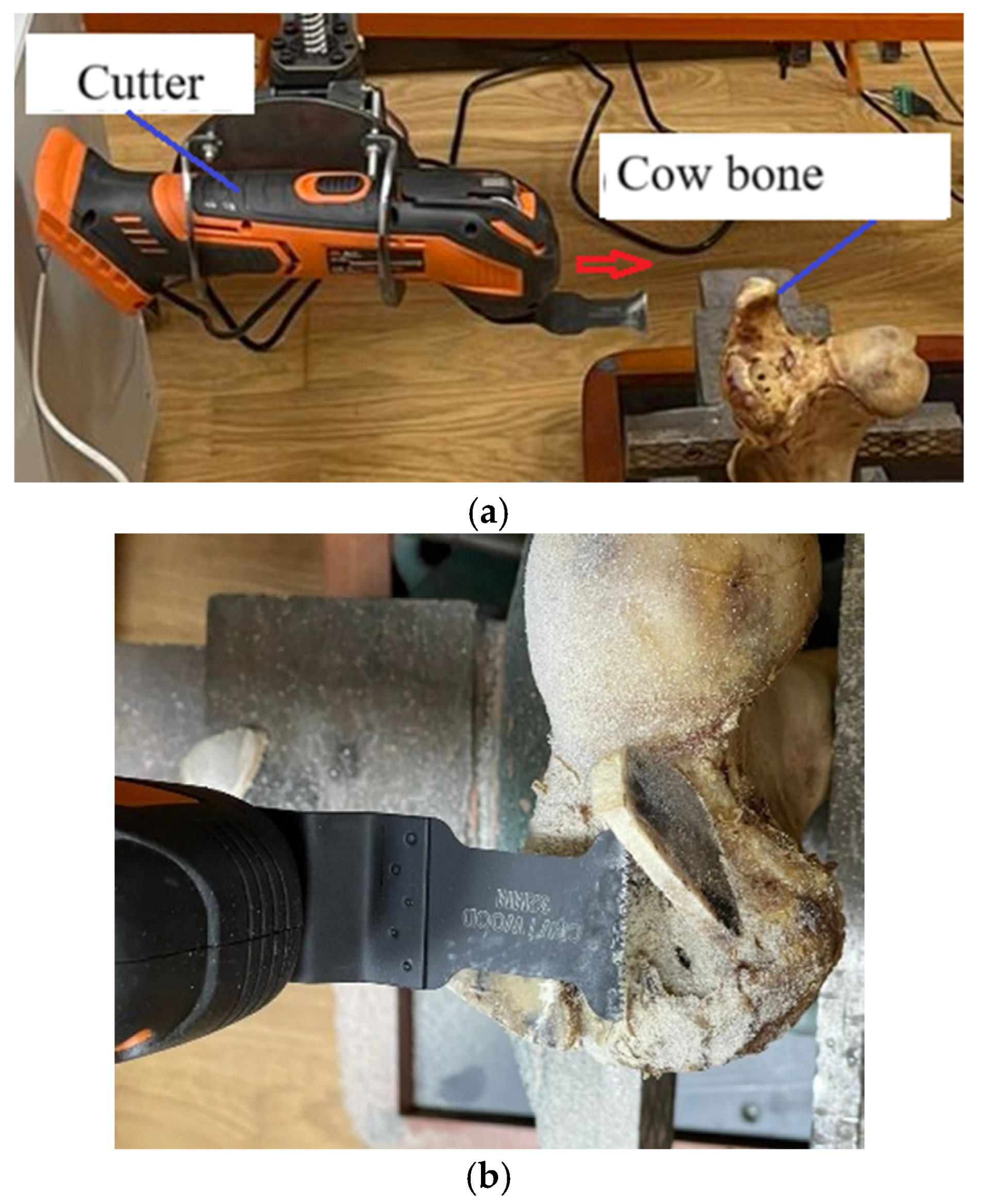
To conduct experimental studies, we will record the movements of the cutter along the X and Z axes. We will fix the cow bone vertically (Figure 12a). We will move the cutter only in the direction of the Y axis, perpendicular to the fixed cow bone, with a constant feed rate of 1.15 mm/s, with a cow bone cutting length of 24 mm (Figure 12b).
Figure 12.
Cutting a cow bone: (a) movement of the cutter in the direction of the Y axis; (b) cow bone after cutting.
Figure 12.
Cutting a cow bone: (a) movement of the cutter in the direction of the Y axis; (b) cow bone after cutting.
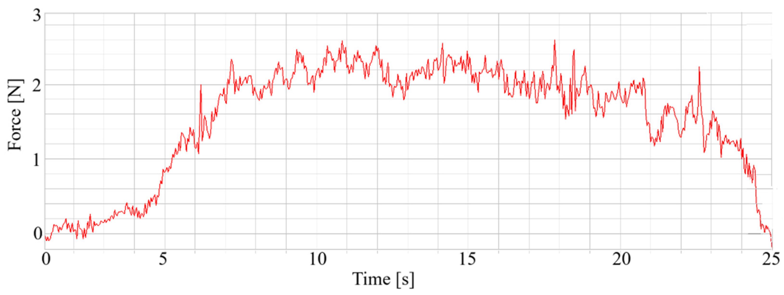
Experimental tests of a simplified prototype of a hybrid Cartesian robot for knee joint surgery showed its performance in cutting hard cow bone. During the experimental study of cutting cow bone, the bone cutting force was determined using a force sensor, the graph of which is shown in Figure 13.
Figure 13.
Cutting force of cow bone when cutting at a constant feed rate of 1.15 mm/s.
The measurement of the linear displacement of the cutter in the Y-axis direction was carried out using a rope displacement sensor BRT50-V5M-RT1 [21] shown in Figure 14. Figure 15 shows the experimental graphs of the linear displacement and feed of the cutter.
Figure 14.
Measuring the linear displacement of the cutter in the Y-axis direction.

Figure 15.
Measured: (a) linear displacement of the cutter; (b) feed of the cutter.
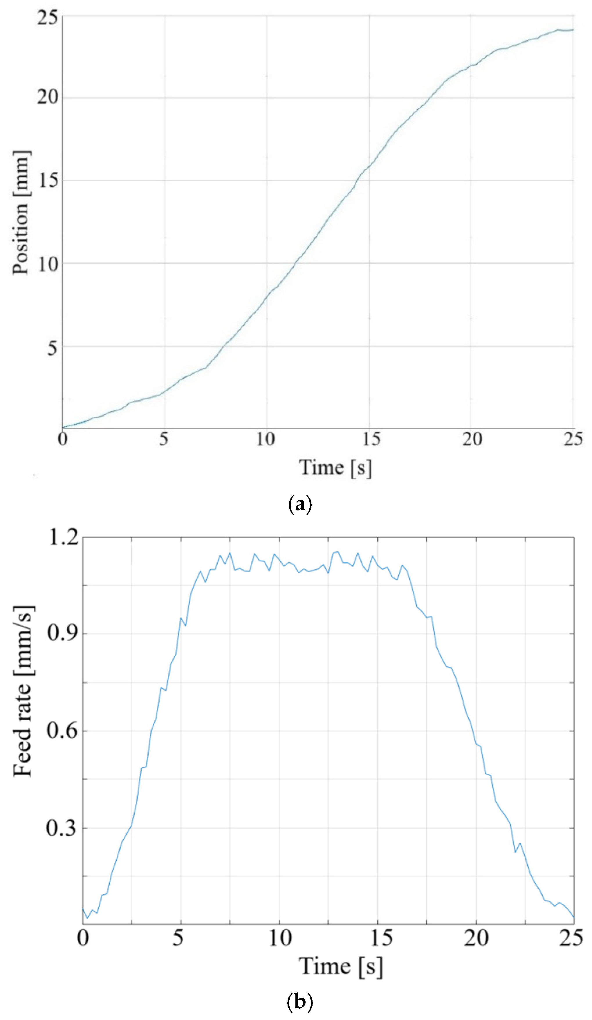
To determine the positioning accuracy of the cutter, 10 measurements of its linear displacement were carried out using a rope displacement sensor BRT50-V5M-RT1 [21]. The measurements were carried out when cutting a cow bone at a given distance of 24 mm, with a constant feed rate of 1.15 mm / s. As a result of the measurements, we obtained the following results: an average positioning error of 0.681 mm and a maximum positioning error of 1.042 mm, which is an acceptable accuracy when cutting hard cow bone.
4. Conclusions
This paper presents the current development of a hybrid Cartesian robot for knee joint surgery. The hybrid Cartesian robot has 6-DoF. The first three links are designed for linear movement of the end effector, and three rotational links are needed to adjust the orientation of the end effector. The end effector of the robot is an orthopedic multifunctional drill, with a force sensor and a 6-axis force sensor built into the handle, which are assembled as a single module. The structure of the hybrid Cartesian robot has increased rigidity and high positioning accuracy of the end effector. The hybrid Cartesian robot has a large workspace, and its forward and inverse kinematics are much simpler than those of traditional serial manipulators and Stewart platform robots.
A 3D model of a hybrid Cartesian robot for knee joint surgery was developed and a simplified prototype was designed based on it. In the simplified prototype of the hybrid Cartesian robot for knee joint surgery, all orientation angles of the end effector are fixed and only the movement along the X, Y, Z axes is considered here. Experimental tests of the simplified prototype of the hybrid Cartesian robot for knee joint surgery showed its good performance when cutting hard cow bone. Graphs of linear movement, feed rate and cutting force of the cow bone cutter were obtained. It was shown that the maximum positioning error of the cutter is within 1 mm, which is an acceptable accuracy when cutting hard cow bone. The simplified prototype of the hybrid Cartesian robot for knee joint surgery provides sufficient accuracy when resecting hard bone and has good prospects for practical use. Further work will consist of developing and manufacturing a full-fledged prototype of the hybrid Cartesian robot for knee joint surgery with 6DOF, i.e., the orientation angles of the end effector will be variable.
Author Contributions
Conceptualization, A.J.; Methodology, K.O. Formal analysis, A.S.; Investigation, A.K.; Writing—original draft, A.A.; Writing—review & editing, M.A.; Supervision, N.K. All authors have read and agreed to the published version of the manuscript
Funding
This research was funded by the Science Committee of the Ministry of Science and Higher Education of the Republic of Kazakhstan Grant No. BR24992820.
Conflicts of Interest
The authors declare no conflict of interest.
References
- Picard, F.; Deakin, A.H.; Riches, P.E.; Deep, K.; Baines, J. Computer assisted orthopaedic surgery: Past, present and future. Med. Eng. Phys. 2019, 72, 55–65. [Google Scholar] [CrossRef] [PubMed]
- Saragaglia, D. More Than 20 Years Navigation of Knee joint surgery with the Orthopilot Device. In Handbook of Robotic and Image-Guided Surgery; Elsevier: Amsterdam, The Netherlands, 2020; pp. 425–441. [Google Scholar]
- Perets, I.; Mu, B.H.; Mont, M.A.; Rivkin, G.; Kandel, L.; Domb, B.G. Current topics in robotic-assisted total hip arthroplasty: A review. Hip Int. 2020, 30, 118–124. [Google Scholar] [CrossRef]
- Enayati, N.; De Momi, E.; Ferrigno, G. Haptics in robot-assisted surgery: Challenges and benefits. IEEE Rev. Biomed. Eng. 2016, 9, 49–65. [Google Scholar] [CrossRef] [PubMed]
- Lang, J.; Mannava, S.; Floyd, A.; Goddard, M.; Smith, B.; Mofidi, A.; Seyler, T.M.; Jinnah, R. Robotic systems in orthopedic surgery. J. Bone Jt. Surg. Br. Vol. 2011, 93, 1296–1299. [Google Scholar] [CrossRef] [PubMed]
- Davies, B.; Harris, S.; Lin, W.; Hibberd, R.; Middleton, R.; Cobb, J. Active compliance in robotic surgery—The use of force control as a dynamic constraint. Proc. Inst. Mech. Eng. Part H J. Eng. Med. 1997, 211, 285–292. [Google Scholar] [CrossRef] [PubMed]
- Beasley, R.A. Medical robots: Current systems and research directions. J. Robot. 2012, 2012, 401613. [Google Scholar] [CrossRef]
- Lonner, J.H.; Smith, J.R.; Picard, F.; Hamlin, B.; Rowe, P.J.; Riches, P.E. High degree of accuracy of a novel image-free handheld robot for unicondylar knee arthroplasty in a cadaveric study. Clin. Orthop. Relat. Res. 2015, 473, 206–212. [Google Scholar] [CrossRef]
- Wallace, D.; Gregori, A.; Picard, F.; Bellemans, J.; Lonner, J.; Marquez, R.; Smith, J.; Simone, A.; Jaramaz, B. The learning curve of a novel handheld robotic system for unicondylar knee arthroplasty. Orthop. Proc. 2014, 96-B Suppl. S16, 13. [Google Scholar]
- Simons, M.; Riches, P. The learning curve of robotically-assisted unicondylar knee arthroplasty. Bone Jt. J. 2014, 96-B Suppl. S1, 152. [Google Scholar]
- https://www.stryker.com/us/en/joint-replacement/systems/Mako_SmartRobotics_Overview.html.
- Ginoya, T.; Maddahi, Y.; Zareinia, K. A historical review of medical robotic platforms. J. Robot. 2021, 2021, 6640031. [Google Scholar] [CrossRef]
- Abdelaal, A.E.; Mathur, P.; Salcudean, S.E. Robotics in vivo: A perspective on human–robot interaction in surgical robotics. Annu.Rev. Control. Robot. Auton. Syst. 2020, 3, 221–242. [Google Scholar] [CrossRef]
- Wolf, A,; Jaramaz, B,; Lisien B,; et al. MBARS: mini bone-attached robotic system for joint arthroplasty. Int J Med Robot 2005, 1, 101–121. [Google Scholar] [CrossRef] [PubMed]
- Song, S.; Mor, A.; Jaramaz, B. HyBAR: Hybrid bone-attached robot for joint arthroplasty. Int. J. Med. Robot. Comput. Assist. Surg. 2009, 5, 223–231. [Google Scholar] [CrossRef] [PubMed]
- Yen, P.; Lai, C. Developing a Hybrid Cartesian Parallel Manipulator for Knee joint surgery, 2006 IEEE Conference on Robotics, Automation and Mechatronics, Bangkok, Thailand, 2006, pp. 1-6. [CrossRef]
- Yen, P.; Hung, S. Cooperative force control of a hybrid Cartesian parallel manipulator for bone slicing. Robotica. 2013, 31, 173–182. [Google Scholar] [CrossRef]
- ZETLAB Company. Available online: www.zetlab.com (accessed on 22 July 2025).
- Arduino IDE. Available online: https://www.arduino.cc/en/software/ (accessed on 22 July 2025).
- P.I.T. cutter (China). Available online: https://www.pit-tools.com/Product/?ppid=148&pid=6&l=en#p6 (accessed on 22 July 2025).
- Rope displacement sensors BRT50-V5M-RT1. Available online: www.briterencoder.com (accessed on 22 July 2025).
Disclaimer/Publisher’s Note: The statements, opinions and data contained in all publications are solely those of the individual author(s) and contributor(s) and not of MDPI and/or the editor(s). MDPI and/or the editor(s) disclaim responsibility for any injury to people or property resulting from any ideas, methods, instructions or products referred to in the content. |
© 2025 by the authors. Licensee MDPI, Basel, Switzerland. This article is an open access article distributed under the terms and conditions of the Creative Commons Attribution (CC BY) license (https://creativecommons.org/licenses/by/4.0/).
Copyright: This open access article is published under a Creative Commons CC BY 4.0 license, which permit the free download, distribution, and reuse, provided that the author and preprint are cited in any reuse.


