
Submitted:
24 July 2025
Posted:
25 July 2025
You are already at the latest version
Abstract
This paper presents the design and validation of the ResourceNet platform, a digital solution with an architecture developed to support the circular economy by valorizing ceramic waste as Secondary Raw Materials (SRMs). Aligned with the EU Circular Economy Action Plan and the Waste Declassification Framework, the platform addresses the logistical and compliance challenges faced by SMEs in remote regions by facilitating the structured exchange of SRM data via an omnichannel digital marketplace. The proposed architecture integrates formal visual modeling techniques and complies with existing standards to ensure transparency, modularity, and traceability.
The research adopts a Process-Driven Architecture (PDA) approach, complemented by a Model-Driven Architecture (MDA), to model the digital logistics of the SRM supply chain. The methodology utilizes BPMN and UML to map business workflows, data interactions, and system behavior. A context diagram anchors the architectural views, supporting alignment between stakeholder concerns and system capabilities. The findings, validated through a case study in the ceramics sector, demonstrate that integrating PDA and MDA enables an interoperable, standards-based platform that supports waste declassification, facilitates SRM traceability, and fosters industrial symbiosis. This positions ResourceNet and the corresponding lessons learned as a scalable solution for advancing digital circular economy ecosystems.
Keywords:
Business Process Diagram
; Process-Driven Architecture Design Pattern
; Circular Economy
; Requirement Engineering
; Cross-sector Cooperation
; Declassification of Waste
1. Introduction
The circular economy model promotes the reuse and recycling of materials traditionally classified as waste [1], transforming them into resources or secondary raw materials (SRMs). Aligned with EU and national policies, particularly the EU's Circular Economy Action Plan under the European Green Deal, this model aims to conserve resources, retain product value, and move away from the linear "take-make-dispose" approach [2]. These initiatives are central to the EU's goal of achieving climate neutrality by 2050, as a significant share of greenhouse gas emissions originates from the extraction and processing of resources.
To address logistics and value chain challenges [3], particularly for small and medium-sized enterprises (SMEs) in remote regions, a digital omnichannel marketplace model is proposed to facilitate the efficient trading of SRMs. The platform architecture supports circular practices by providing SMEs with access to a mediation gateway that fosters cross-sector collaboration [4]. It offers integrated digital services at no added cost, thereby enabling sustainable partnerships and helping SMEs source secondary resources. The model also encourages consumer engagement, allowing end-users to co-create product offerings and customize eco-sustainable packages according to their preferences.
This approach has been validated through the development of a prototype, called the ResourceNet platform, which was co-designed with key stakeholders in the ceramics sector during early-stage laboratory testing. The platform facilitates the structured exchange of information between suppliers, acquirers, and other stakeholders in the SRM value chain. Its core goal is to optimize the collection, tracking, and revaluation of ceramic waste by integrating sector-specific information, waste typologies, and reuse scenarios, ultimately enhancing circularity in the ceramics industry.
ResourceNet aims to foster eco-innovation by promoting industrial symbioses that improve both environmental and economic performance. It establishes a standardized data governance model to manage SRMs, reduce reliance on virgin raw materials, and generate value-added products from a life cycle perspective [5]. The platform serves two main functions: (1) to act as an interoperable marketplace that aggregates and shares data on the availability and origin of SRMs, and (2) to offer a reusable open architectural framework to support waste recovery in the ceramics sector while enabling integration with other industries. The ResourceNet platform is fully aligned with the Waste Declassification Framework, ensuring compliance with national and EU regulations by incorporating mechanisms for validating, updating, and tracing all SRM data registered in the Marketplace. This ensures that up-to-date information is maintained whenever new By-product declarations are issued or existing records are updated.
The platform adopts an open-access architecture for real-time data streaming across the supply chain, connecting SRM providers and consumers while involving intermediaries where necessary. Its system design aligns with the principles of ISO 42010:2023, focusing on transparency, interoperability, and modularity. ResourceNet supports service-level agreements (SLAs) with flexible service configurations and operational workflows anchored in a data governance workflow. To ensure traceability, all actions within the SRM value chain are digitally documented. These features position the platform as a key enabler for cross-sector collaboration and the transition toward a digital circular economy.
1.1. Ceramic Sector Contextualization - Waste Declassification Directive
The ceramic industry remains a strategic industrial sector in Europe, particularly in countries such as Portugal, Spain, Italy, Germany, and France. It spans a wide variety of applications, from structural ceramics (e.g., bricks and tiles) to advanced and decorative ceramics (e.g., sanitary ware, tableware, and high-performance components). The sector is economically significant, contributing to industrial GDP and sustaining regional employment [6]. However, ceramic manufacturing is inherently resource- and energy-intensive, depending on natural raw materials such as clay, feldspar, and silica, and generating substantial waste throughout production and post-consumer phases [7].
Environmental pressures and rising sustainability standards are prompting the sector to embrace circular economy practices [8]. These include energy-efficient technologies, reuse of industrial residues, eco-design strategies, and digital process optimization. In this context, digital platforms like ResourceNet provide an integrated approach to identifying, managing, and valorizing residual materials across the supply chain. Nonetheless, the transition from waste to reusable resource hinges on regulatory enablers, specifically, mechanisms that define when a material can cease to be classified as waste [9].
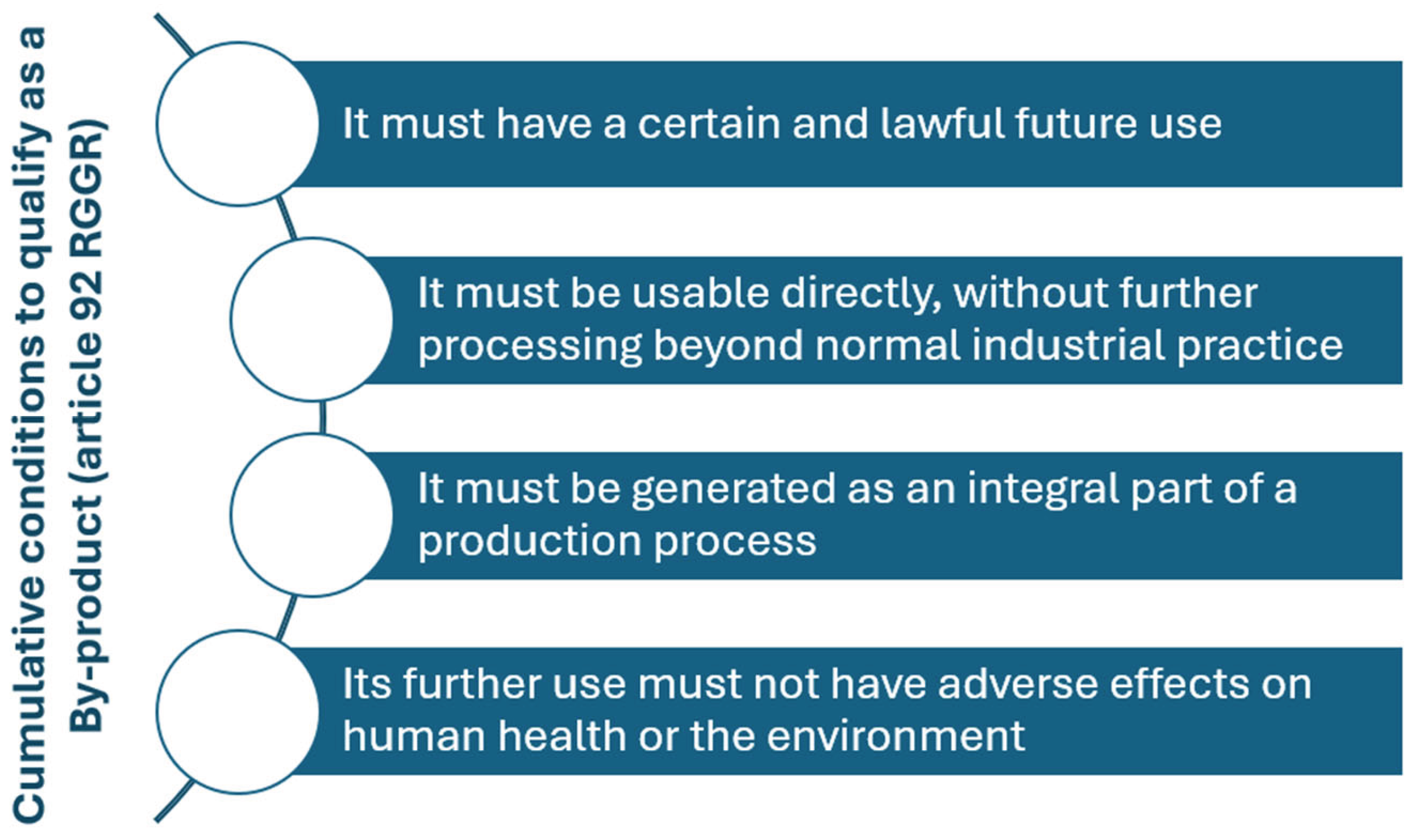
The Waste Framework Directive (Directive 2008/98/EC), as implemented in Portugal through Decree-Law no. 102-D/2020 as revised by Decree-Law no. 24/2024 [10], introduces legal provisions for waste declassification. This process enables specific materials to be recognized as By-products or SRM, provided they meet the cumulative regulatory criteria outlined in Article 91 of the national waste management regime (RGGR). These include ensuring that the material results from a production process, has a defined use, does not require further processing beyond standard industry practices, and complies with applicable environmental and safety standards [11]. For the ceramic industry, these provisions enable the legal reintegration of production residues, such as unfired rejects or ceramic sludge, into new production cycles.
The implications of this regulatory shift are substantial. By enabling waste declassification, the ceramic industry can reduce its dependency on raw materials, minimize disposal costs, and lower its environmental footprint. Moreover, this framework aligns with strategic European objectives for climate neutrality and resource efficiency. The integration of declassified materials into a digitally governed SRM marketplace, such as the one modeled by ResourceNet, represents a key innovation. It ensures traceability, compliance, and interoperability across stakeholders, allowing ceramic manufacturers to align operations with both sustainability goals and regulatory mandates. As such, waste declassification is not merely a legal mechanism but a strategic lever for innovation and competitiveness within the sector.
Figure 1.
The cumulative conditions to qualify as a By-product (article 9 of the RGGR - source: APA).
Figure 1.
The cumulative conditions to qualify as a By-product (article 9 of the RGGR - source: APA).
Since 2023, Portugal has adopted a self-declarative waste declassification procedure, enabling individual producers or sectoral associations, such as APICER (www.apicer.pt), to initiate the process of recognizing production residues as By-products. The process begins with the submission of an official form to the Portuguese Environment Agency (APA), which details the material's origin, intended use, and supporting documentation (e.g., laboratory analyses, quality assurance reports, usage contracts). This is followed by technical validation from a recognized Collaborative Laboratory (CoLAB) or Interface Centre, such as CTCV (www.ctcv.pt), which issues a validation declaration. Once the complete dossier is submitted to APA, the agency verifies compliance and, if successful, issues an official By-product Declaration within 15 working days. This framework emphasizes efficiency, transparency, and operator accountability, with APA requiring annual reporting on the quantities produced and transferred. In this domain, APICER acts as a facilitator of sector-wide submissions, streamlining adoption for ceramic manufacturers.
In the ceramic industry, this legal mechanism has already enabled the declassification of key production residues, including unfired and fired ceramic rejects, ceramic sludge, and trimming dust (By-product Declaration No. 9/2017). The sector also benefits from cross-industry reuse opportunities. By-products such as clarification sludge, lime kiln ash, carbonate sludge, and foundry casting sand, originating from the pulp and metal sectors, have been approved for reintegration into ceramic production. These materials can be processed and used as partial substitutes for virgin raw materials, offering cost savings and environmental benefits. However, strict quality assurance, traceability, and compliance documentation remain essential to demonstrate safety and technical viability. The approach supports circular economy goals by reducing disposal needs, lowering costs, and increasing access to certifications and incentives, while also promoting industrial symbiosis [12]. Exporting firms must ensure that the destination country also recognizes By-product status; otherwise, materials are treated as waste under international movement regulations.
1.2. Considerations on the Proposed Approach
Before presenting the proposed architectural approach, it is helpful to understand BizDevOps (a.k.a. DevOps 2.0). This modern approach to product development extends traditional DevOps by integrating business stakeholders directly into the software development lifecycle, ensuring alignment between business goals, technical design, and operational execution. BizDevOps promotes collaboration across business, development, and operations teams, placing customer needs at the centre of the development process [13]. A defining feature of BizDevOps is its focus on continuous feedback and agile workflows from the earliest stages, including system analysis and requirements specification. Involving business users early also allows functional requirements to be refined iteratively, ensuring that development remains continuously aligned with user expectations and business strategy.
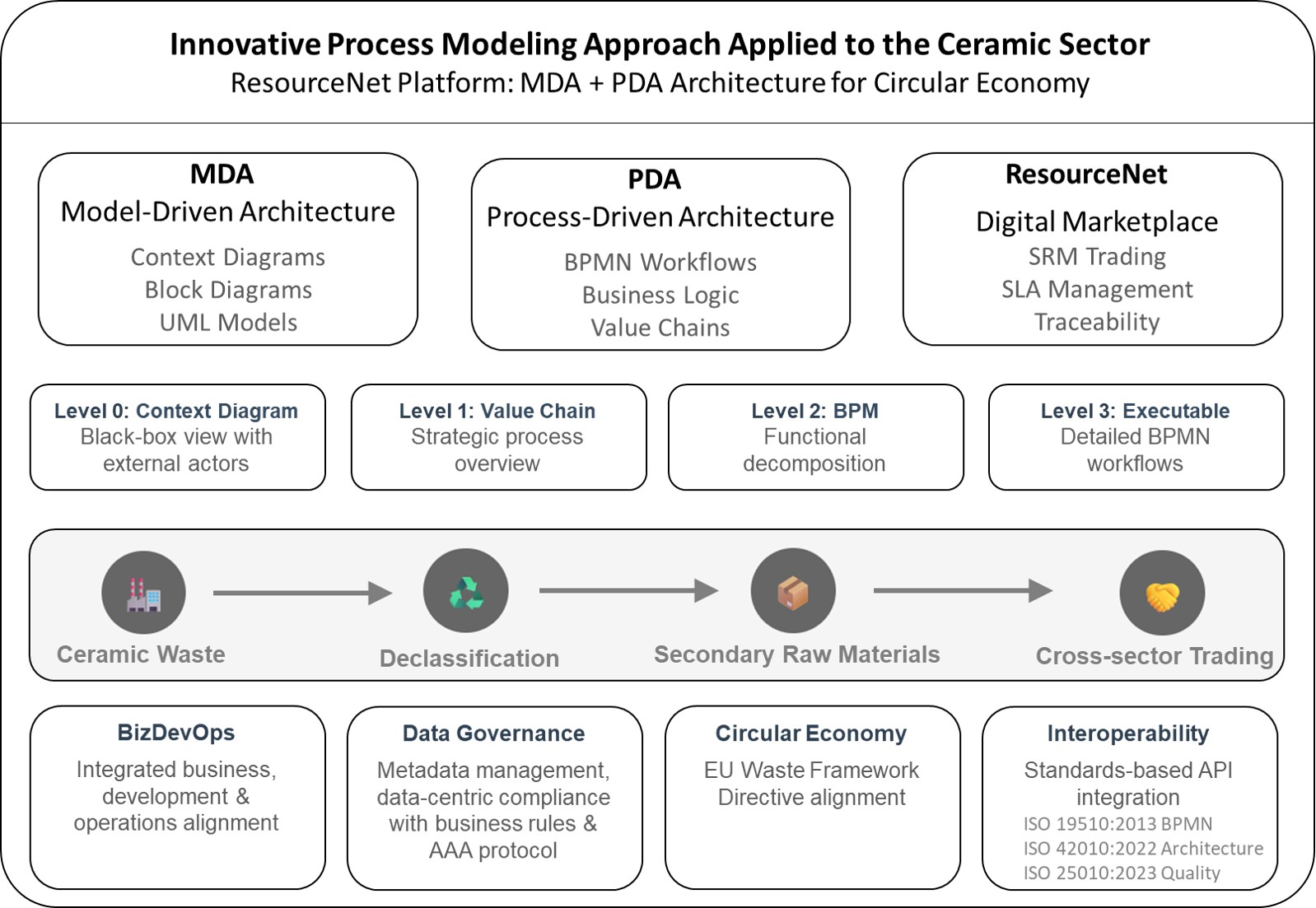
Figure 2 illustrates how BizDevOps was applied to integrate two architectural patterns: Model-Driven Architecture (MDA) [14] and Process-Driven Architecture (PDA) [15]. The context diagram serves as a foundational artefact to coordinate both approaches, supporting the generation of architectural views that reflect the conceptual system model from multiple viewpoints. This integration enhances traceability across informational artefacts, linking business processes, stakeholder concerns, and system requirements [16]. It also provides structured guidance for modelling business processes in a way that aligns them with architectural analysis and design objectives.
In modern software engineering, particularly for web-based systems, aligning rapidly changing business processes with scalable solutions has become increasingly complex. Traditional architectural methods, based on data models or functional decomposition, often fall short in supporting dynamic workflows, rapid iteration, and cross-functional collaboration. The PDA lifecycle addresses this by placing business processes at the center of system design. Rather than focusing solely on data structures or isolated services, PDA structures system logic around the sequence and intent of business activities [17], ensuring that application behavior aligns with both functional requirements and strategic goals. The approach illustrated in Figure 2 leverages formal visual modeling techniques, such as Business Process Modeling Notation (BPMN) and Unified Modeling Language (UML), to define workflows, structure data interactions, and map system behavior. These standardized notations enable clear and analyzable models of business logic and architecture, thereby enhancing traceability and facilitating effective communication with stakeholders. In line with ISO 19510:2013, BPMN is used to create Business Process Diagrams (BPDs), offering a unified visual language that connects process design with system implementation. By integrating PDA and MDA, the BizDevOps team ensures a system architecture that is both technically robust and business-aligned, as well as scalable to meet the evolving needs of users.
The context diagram marks the starting point for defining the System of Interest (SoI). Since the system is not fully defined at early stages, it is depicted as a Black Box, allowing the BizDevOps team to focus on external interactions rather than internal implementation. The diagram illustrates key actors (e.g., users, third-party platforms, regulatory entities) and outlines the system's boundaries, interactions, and data flows. This high-level view fosters a shared understanding across business, development, and operations teams by clearly defining the system's purpose, integration points, and environmental constraints. It also aids in identifying high-level requirements and guiding the architectural scope.
As development progresses, the MDA approach complements PDA by introducing a block diagram that breaks down the internal structure of the SoI [16s,18]. This diagram organizes the system into functional modules, typically across presentation (frontend) and business logic (backend) layers. It visualizes control flows and communication paths, highlighting module responsibilities and data dependencies. This modular view facilitates collaborative design decisions, enabling early alignment and improving the system's structural coherence [19]. Together, PDA and MDA offer a cohesive framework for modelling complex systems, balancing business logic with technical architecture.
2. The Modeling Approach within the ResourceNet Case Study
2.1. Model Driven Architecture
At the beginning of a software development project, the project manager works closely with business users to define the SoI. In line with ISO 42010:2022, this starts with the construction of a context diagram, which represents the SoI as a Black Box. The goal is to identify all external actors, systems, and environmental factors interacting with the SoI, along with the nature of those interactions. This top-level view establishes the system's boundaries and clarifies external dependencies before addressing any internal structures.
Following the context definition, the team develops a preliminary block diagram that decomposes the SoI into functional modules distributed across the classic three-layer architecture: presentation, business logic, and data layers. Each module is characterized by its functional responsibility and mapped to stakeholder interactions. For example, GUI modules support human actors via dashboards or forms, while backend APIs handle machine-to-machine integration. To reinforce this alignment, a CRUD (Create, Read, Update, Delete) matrix is produced. This tool links stakeholders to the software components and data entities with which they interact, distinguishing between human and system actors. The CRUD matrix ensures traceability and helps validate functional coverage from the outset.
In the preliminary phase of software requirements analysis and specification, MDA is particularly effective when used in conjunction with context diagrams. By abstracting the SoI as a Black Box, context diagrams focus on system interfaces rather than implementation. MDA extends this by formalizing these interactions into structured models [20], which evolve into behavioral and architectural representations. This formal modeling helps define system responsibilities and interactions early in the lifecycle, reducing ambiguity and ensuring consistency.
The block diagram complements this by presenting a modular internal view of the SoI, offering clarity on how the system is organized and how different modules communicate. A supporting table documents the role of each module, making it easier to understand the contribution of each component. When integrated with the CRUD matrix, this approach ensures a comprehensive mapping between stakeholders, system functions, and data flows. With this structure in place, the project enters the initial phase of software requirements specification. Functional and non-functional requirements are documented, ideally following the ISO 25010:2023 standard.
MDA supports the representation of multiple architectural viewpoints (i.e., structural, behavioral, and informational), facilitating a clearer understanding of how the system will behave in different contexts and how it satisfies stakeholder expectations. This reduces the risk of misunderstandings and supports iterative refinements, particularly useful in complex, regulated environments. The synergy between MDA and PDA becomes especially valuable in agile environments that adopt a Minimum Viable Product (MVP) approach. While PDA focuses on executable process models and workflows, MDA complements it by formalizing the system's structural and logic layers. This alignment enables the transition from business processes to system implementation, supporting rapid prototyping and continuous delivery pipelines.
In a BizDevOps setting, this integrated approach enables all stakeholders (e.g., business analysts, developers, and operations staff) to collaborate around shared, model-driven artifacts. These models guide development decisions and provide traceability throughout the lifecycle. MDA thus fosters transparency, improves communication, and enhances adaptability to evolving requirements, ensuring that both technical robustness and business alignment are maintained. This structured methodology supports scalable and agile development, laying a solid foundation for systems that must meet changing demands and comply with regulations.
2.2. Process-Driven Architecture Lifecycle – Technical Overview
Process models communicate key information about business tasks, responsibilities, and interaction points, enabling the BizDevOps team to follow and understand data workflows. This clarity is particularly helpful for onboarding new members, as it provides clear and accessible documentation on how processes function. Nevertheless, despite the fact that BPMN is the ISO standard for modeling processes, it is not designed to support high-level process landscapes [21]. It lacks native elements for modeling sequential relationships, hierarchical structures, and macroprocess types at the landscape level, prompting many practitioners to rely on custom diagrams or use value chain diagrams as alternatives.
In this context, value chain diagrams offer a business-focused, top-down view of the organizational processes relevant to the System of Interest (SoI). These process landscape models help visualize macroprocesses and their interdependencies, improving communication across departments and setting the groundwork for more detailed process modeling. Within the scope of this work, high-level value chains outline the SoI's process architecture, identifying business services across key functional domains. Rather than attempting to map every process, the approach enables targeted refinement of workflows within specific business areas covered by the ResourceNet platform scope.
While value chain diagrams provide strategic insight, BPMN is applied at lower levels to model sub-processes and tasks with the operational detail required for system specification. Together, these hierarchical models serve as blueprints for system development, fostering collaboration between stakeholders and development teams (DevTeam). They help identify bottlenecks and inefficiencies early, ensuring system design evolves in sync with business goals. As illustrated in Figure 3, the multilevel structure of PDA progressively refines software requirements.
Initially, at the first two levels, processes are represented as Black Boxes using value chain diagrams, abstracting internal details to highlight structure and relationships between the macroprocesses, which are later elaborated into detailed BPMN diagrams. This approach supports continuous improvement and reinforces alignment between business needs and system architecture, thereby enhancing overall system effectiveness (e.g., early identification of bottlenecks and inefficiencies). To ensure consistency and coherence across layers, the multilevel structure is defined as follows:
- Level 0 – Context Diagram (Black-Box View): This level defines the SoI as a Black Box, focusing on its external interactions with stakeholders, systems, and roles. It outlines environmental boundaries, dependencies, and high-level responsibilities. Two interface types are distinguished: carbon processors (GUIs for human interaction) and silica processors (APIs for system integration). GUIs introduce complexity due to human unpredictability, usability, and security issues, while APIs are more deterministic and easier to validate. This diagram helps scope the architecture and define key communication channels, serving as a foundation for requirements engineering by clarifying the roles of actors and the expected interactions between the system and its users.
- Level 1 – Process Landscape Diagram (Strategic Overview): This level provides a strategic view of the organization's value chain, mapping primary and supporting business areas through high-level process groups, often aligned with or related to the project scope. These are abstracted from implementation details but establish ownership, information flow, and potential integration points. It helps correlate business domains to software modules (e.g., GUIs in the presentation layer and business rules at the application layer) and distinguishes between human and machine interaction needs. The diagram complements the block diagram by positioning business processes within the architecture, promoting a shared understanding of the system's high-level logic and strategic business alignment.
- Level 2 – Business Process Modeling (Functional Decomposition): This level describes internal workflows for selected processes, documenting the sequences of activities, decisions, and inputs and outputs. The outcome is a functional decomposition of the selected processes, showing dependencies, responsibilities, and interactions between roles, organizational units, or systems. This level provides the functional scope and behavioural context for defining technical requirements and refining user stories. Artefacts such as business process diagrams or event-driven process chains may be used to complement the characterization of the SoI at this stage. It bridges abstract process overviews with tangible behavioral patterns, enabling precise analysis and stakeholder validation.
- Level 3 – Executable Process Models (Detailed Specification): This level formalizes business logic into executable workflows using BPMN constructs (tasks, gateways, events, pools/lanes). It specifies how processes are orchestrated across manual and automated actions, aligning system behavior with business intent. Data objects are mapped to technical elements (e.g., UML class diagrams, state machines), and interfaces are detailed through wireframes (for GUIs) or schemas (for APIs). Business rules are externalized using Decision Model and Notation (DMN) or expressed in Decision Management Languages (DML) to promote clarity and modularity. Separating rules from process logic improves traceability, supports regulatory compliance, and simplifies updates. This level provides a detailed, executable model of workflows, roles, and interactions, serving as both a technical blueprint for developers and a collaborative reference for analysts and operations teams. It ensures that the implemented system remains aligned with business logic, operational goals, and evolving policy or compliance requirements.
- Level 4 – Sub-Processes (Modular Detail): This level introduces sub-processes, offering a deeper level of granularity for tasks that are too complex to be modelled inline at Level 3. This modularity enables the isolation of complex or reusable logic into modular sub-processes using BPMN's call activities or embedded constructs. These units handle domain-specific, repetitive, or cross-cutting concerns (e.g., authentication, data validation) and support reusability and maintainability. They align with backend architecture, often mapping to microservices or bounded contexts. This level refines the system's internal behavior by integrating sub-process logic into the broader workflow, facilitating consistent enforcement of rules and policies. When linked to block diagrams, Level 4 provides backend behavioral depth and supports modular evolution of large-scale, compliant, and maintainable systems.
Integrating MDA and PDA under the ISO 42010:2022 standard provides a cohesive framework for specifying and analysing complex systems. MDA contributes structural and behavioural models from a software engineering perspective, while PDA complements it with an operational view focused on business logic and process flows. Together, they deliver a complete representation of the SoI, bridging technical and business concerns. PDA also addresses critical data-related requirements (e.g., security, privacy, performance, and scalability) supporting traceability from stakeholder needs to system behaviour. This is especially valuable in multitenant environments, where modular and scalable solutions must accommodate diverse user and tenant requirements [16].
Using BPMN, as defined in ISO 19510:2013, PDA formalizes workflows through BPDs, which utilize standardized symbols to visually represent business activities. Each BPD activity typically correlates with one or more functional requirements (e.g., a "Submit Request" task signals the need for a system to accept and process user inputs). These models guide system specification by linking business needs to corresponding software components and services. At the backend level, BPMN represents business rules as distinct activities and models interactions with external systems through Service tasks, effectively specifying the technical requirements for interoperability via APIs or other service interfaces. This facilitates the orchestration of internal workflows alongside external integrations. Additionally, BPMN supports the identification of non-functional requirements related to user interactions. User tasks involving GUIs highlight concerns such as usability, accessibility, responsiveness, and adherence to ISO 25010:2023. For instance, a "Report an Issue" task implies the need for a structured, user-friendly form with proper input validation to ensure a positive and efficient user experience (i.e., user satisfaction and adoption).
By combining MDA and PDA, a dual system architecture perspective is achieved: BPDs represent external behaviour from a business process viewpoint. At the same time, MDA defines the internal structure and implementation logic through UML class, component, or service diagrams. A BPD activity, such as the "Marketplace service report," is thus mapped to backend services, validation routines, and integration points described in MDA artifacts. This integration ensures technical traceability of business operations, improves communication between stakeholders, and strengthens system alignment with both functional and non-functional requirements.
2.3. Data Governance Framework Within the Process-Driven Architecture Lifecycle
In addition to the architectural styles discussed earlier, a Data Governance Framework (DGF) embedded in the PDA lifecycle can be seen as another layer to the data processing ecosystem. It establishes policies, roles, and standards for managing data as a strategic asset throughout its lifecycle, aligning data handling with business rules, compliance, and user expectations. Within PDA, which links system architecture to business processes, the DGF enhances data quality, traceability, and consistency, improving integration across workflows and supporting informed decision-making.
In cloud-based and big data systems, the DGF enables the orchestration of ingestion pipelines, metadata management, and access controls. By linking data requirements directly to BPMN process activities, the framework ensures that data availability, security, and integrity are addressed within the system's functional and non-functional requirements. For example, user-facing services that require real-time data or handle sensitive information can be governed by policies that address latency, encryption, or anonymization. This integration strengthens resilience and ensures data is usable across analytics, reporting, and AI services.
A common challenge in data platform engineering is the absence of standardized methods to guide architectural decisions. Platform design often relies on the experience of practitioners navigating fragmented ecosystems of tools and services. The proposed architectural approach helps address this by linking architectural choices to business processes, allowing decisions to be based on regulatory, quality, or performance criteria. This promotes better justification of design options and reduces the risk of resource misallocation.
Combining MDA and PDA is particularly effective in big data and cloud environments, where data governance is a critical success factor. Rather than incrementally adding solutions for each requirement, the BizDevOps team must resolve conflicts and optimize trade-offs across evolving needs. Identifying which parts of the system are stable and which are likely to change enables evolutionary development with minimal disruption. In this context, system design becomes a distributed effort, requiring flexibility and traceability to accommodate rapid updates without sacrificing integrity or performance. Multitenancy introduces complexity, necessitating adaptable designs that cater to diverse user needs while maintaining service quality. In this case, the BizDevOps team must anticipate changes in services, data use, and application ecosystems and sustain alignment between evolving requirements and implemented functionalities.
This approach positions data management as a first-class architectural concern, with BPMN used to model data-driven workflows. Activities in BPMN, classified as user, service, or business rule tasks, govern how data is captured, transformed, and stored. User tasks support input and interaction, service tasks integrate APIs or external systems, and business rule tasks define logic or computation. These tasks can be automated, assigned to roles, and tracked, ensuring accountability and timely action. BPMN thus offers more than workflow modeling: it supports precise specification of requirements and behaviour, bridging the gap between analysts and developers, and meets both functional and data-centric requirements. It captures fine-grained interactions and decisions, offering more depth than high-level value chain diagrams. Combined with MDA, this modelling ensures that every business function is traceable to technical implementations, reinforcing governance and system alignment.
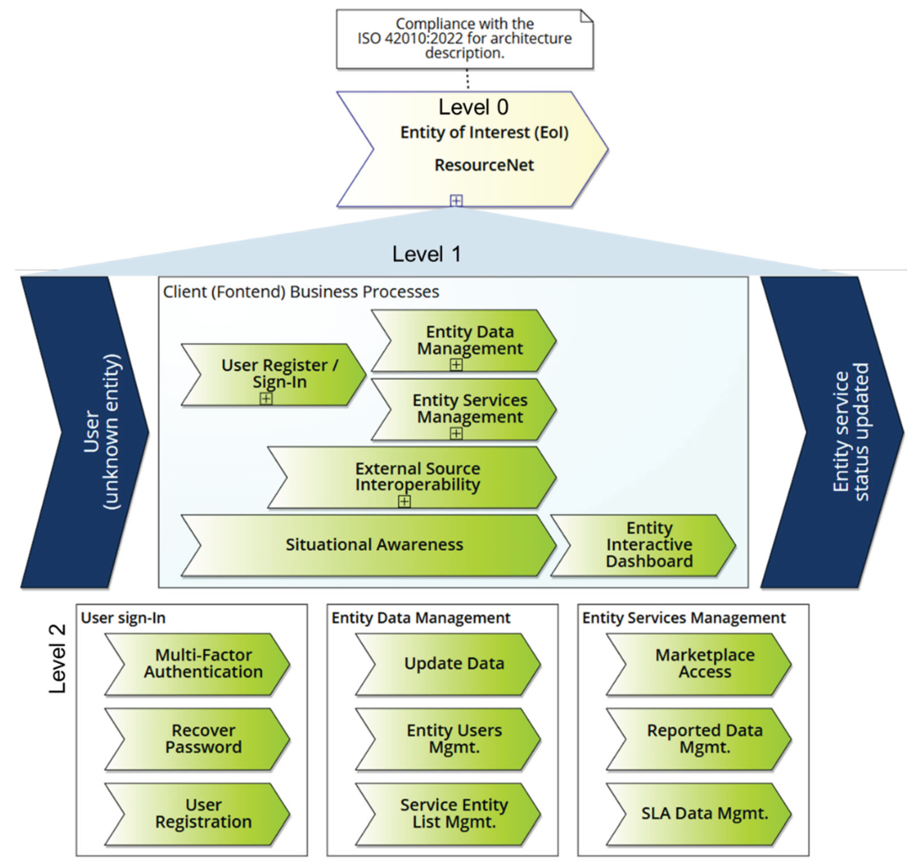
The conceptual model in Figure 4 follows the ISO 42010:2022 notation to represent the target system (ResourceNet), which serves as the case study. Although the standard now refers to "entity-of-interest" (EoI), this paper retains the familiar term "system-of-interest" (SoI) for clarity and simplicity, avoiding in-depth technical distinctions beyond its scope. The diagram presents a simplified context model, framing the system as a network of socio-technical entities that interact to meet organizational information needs. Section 3 further elaborates how the model captures stakeholder concerns within a specific environment, enabling structured and multi-perspective architectural communication.
The diagram serves as a conceptual blueprint for the ResourceNet platform, promoting alignment between stakeholders and development teams. Explicitly modeling organizational processes enables the early identification of inefficiencies and ensures that system evolution aligns with user needs and strategic goals. In line with the PDA landscape, the SoI is introduced at Level 0 as a Black Box, followed by Levels 1 and 2, which map the process landscape via value chain diagrams. These processes are abstracted as Black Boxes to conceal internal complexity while revealing structural dependencies and interactions. This abstraction supports collaboration on high-value-added services and the negotiation of service-level agreements (SLAs) through configurable or confirmable service options. It provides the BizDevOps team with a high-level view of the system's process architecture, enhancing design and operational alignment. Section 3 presents examples of BPDs that illustrate these high-level processes and their interrelations.
Figure 4.
The system is mapped as a black-box with a drill-down into Level 1.
The paper proposes an approach that begins by mapping business processes and their associated data requirements, and then incrementally develops a data platform architecture tailored to those needs. Rather than attempting to prescribe a one-size-fits-all solution, the methodology supports informed, user-centric service composition grounded in process context. Doing so bridges the gap between abstract data governance principles and practical platform engineering, guiding the selection of technologies from within a complex service ecosystem. This strategy ultimately ensures that the data platform supports technical interoperability and delivers value through purposeful, governed, and context-aware data exploitation.
3. Data Governance Framework – Case Study Example
This section presents research findings on implementing a DGF designed to keep stakeholders and decision-makers informed about current and future material needs within the ceramics sector for the implementation of a circular economy, where waste and subproducts can be reused by other players within the same sector or from different industries, such as players in the construction sector. This approach balances production demands with the use of reusable and recycled materials, ensuring alignment with the EU Waste Framework Directive (Directive 2008/98/EC) regarding the recycling of ceramic waste [11]. This directive promotes a "circular economy" approach, aiming to minimize waste generation and maximize resource efficiency, including the promotion of recycling and other recovery methods.
The proposed solution employs an architectural approach with an isolation layer that orchestrates communication between the software modules in the presentation layer and the application layer subsystems. It incorporates an open-access platform for message streaming across the supply chain, connecting suppliers and consumers of SRM and involving intermediaries to facilitate service delivery. The goal is to promote cross-sector cooperation, which is necessary for a digital transition to a circular economy.
3.1. System of Interest – Context Diagram
In software engineering projects, a context diagram provides a high-level view of the interactions between the SoI and external entities. Often referred to as a Level 0 data flow diagram, it establishes a shared understanding of the system's operational environment. The diagram outlines the system's main components, external actors (e.g., users or other systems), and the flow of information between them, clearly defining the system boundaries and its relationships with the surrounding environment. It helps clarify how the system integrates with an organization's broader infrastructure and business processes, identifying system actors, scope, and interfaces. By presenting a unified perspective, it supports the early identification and management of requirements, dependencies, and data exchanges, ensuring alignment with stakeholder concerns across the development lifecycle.
Figure 5 illustrates this by showing the information workflow required to operationalize the SRM supply chain, highlighting the interactions among various stakeholders. The diagram supports the transition toward a circular economy by mapping digitalized logistics processes within the supply chain, promoting sustainability and efficient resource use. One of the diagram's main objectives is to establish traceability throughout the supply chain, tracking each order from initiation to delivery. This level of visibility is particularly relevant for organizations in the ceramics sector, where traceability ensures compliance, quality control, and optimized resource management.
Some stakeholders are directly interested in the SoI, while others are impacted by the opportunities the system can provide based on their role when interacting with it. Table 1 provides a brief introduction to the entities (i.e., stakeholders) participating in the digital Marketplace deployed by the system. The table also outlines the stakeholders' interests, expressed as concerns about the SoI or the architecture with which they are familiar.
These perspectives reflect how stakeholders interpret the SoI within a specific context, shaped by their concerns and responsibilities, and are inherently subjective. Each perspective can give rise to one or more architectural concerns, which is why architectural viewpoints are often structured around these stakeholder perspectives. Within the scope of the project, four distinct user profiles were defined, each with a dedicated role in managing information. The legitimacy and relevance of a stakeholder's concern are often linked to their role, such as platform owner, SRM supplier, consumer, or SRM carrier or processor. Including these stakeholders enables the achievement of a shared understanding of the ResourceNet platform, as their perspectives directly influence how the system should be designed and understood.
3.2. Operational Process – Data Governance
The ResourceNet platform defines a set of user profiles aligned with access control and data governance requirements [22], ensuring compliance with the Authentication, Authorization, Accounting (AAA) protocol [23]. These roles establish hierarchical permissions for managing data and services and are critical for supporting traceability, auditing, and secure information flows across the platform.
- Administrator User (A-User): By default, the user who registers an entity is assigned the A-User profile, acting as the administrator of that entity's record. Once the registration request is approved, the entity record becomes active, granting the A-User full CRUD rights and access to permission management services. A-Users can assign additional users to their entity with A-User, M-User, or S-User profiles. An A-User may be associated with multiple entities.
- Master User (M-User): The M-User has permissions similar to the A-User, including CRUD access and user management within the entity (or across grouped entities) to which they belong. However, M-Users cannot modify A-User accounts or access platform-wide settings. M-Users may also be associated with multiple entities and are responsible for managing users with M-User and S-User profiles.
- Standard User (S-User): This profile grants read access to entity-level data and allows CRUD operations over data elements specific to the entity to which they are linked. S-Users can add or update services and manage notifications triggered by workflows, especially in cases where the user is designated as a point of contact for SLA participation. The role is essential for operational data entry and service maintenance.
- Owner User (O-User): This is a supervisory role assigned to the governing body responsible for the overall integrity and validation of data within the ResourceNet platform, such as APICER. The O-User has read-only access to platform data but can approve or reject entity registration requests and change the status of entity records. The O-User monitors data quality, oversees behavioral compliance, and can suspend user or entity access upon detecting irregularities or suspicious activity.
- Regulator User (R-User): Typically representing regulatory authorities in the ceramics sector, the R-User profile allows read-only access to all platform data, supporting compliance and regulatory oversight.
To support accountability and traceability, ResourceNet implements a robust auditing mechanism that logs all Create, Update, and Delete (CUD) operations. This audit log reinforces the platform's compliance with the AAA protocol. Additionally, sessions are automatically terminated after a predefined period of inactivity, ensuring secure logout and preventing unauthorized access.
The ResourceNet platform features a standardized layout comprising three main sections. The left sidebar provides direct access to core services. At the same time, the top menu contains cross-cutting functionalities available throughout the platform, such as account settings, language preferences, alerts, and configuration options. The central workspace area dynamically adjusts according to the selected sidebar option, presenting the corresponding content in an interactive layout. This paper focuses on two key modules accessible via the sidebar: Marketplace and SLA.
The Marketplace module comprises two tabs: Marketplace and Reported. The first displays a searchable, filterable list of published services, with options for metadata expansion, side previews, and map-based visualization to support spatial decision-making. The Reported tab is reserved for users affiliated with entities that have submitted new services, allowing them to define criteria for automated service matching using a built-in algorithm. This facilitates SLA discovery by aligning supply and demand based on dynamic business rules.
The SLA module also features two tabs: Participant and Owner. The Participant tab lists SLAs in which the user's entity has been invited to collaborate, displaying workflow status, service metadata, and contact details of other involved parties. The Owner tab enables entities initiating SLA searches to manage partnerships. By leveraging ResourceNet's matching algorithm, SLA owners can identify relevant published services and invite selected entities to formalize collaboration. Once accepted, the SLA workflow is activated and notifications are dispatched to all participants.
In a typical operational scenario, a supplier may publish a service offering a specified quantity of SRM, including details such as the reference price and the frequency of availability. Potential consumers can utilize ResourceNet's automated matching and negotiation features to identify relevant services and initiate B2B agreements through the SLA framework. The platform ensures compliance with applicable legal and regulatory requirements by allowing entities to upload mandatory formal documentation, such as certifications, licenses, or declarations of conformity, depending on the nature of the reported SRM. All submitted information, including entity and service metadata, is logged and versioned to support traceability and auditability. This functionality enhances trust, accountability, and transparency throughout the supply chain, allowing platform administrators and regulatory users to verify the integrity of data, monitor deviations, and take corrective actions when anomalies or non-compliance events are identified.
Figure 6 presents the business process model for the Marketplace module, developed using BPMN 2.0 notation. This representation corresponds to the third level of detail in the layered architecture introduced in section 0 (see Figure 3), providing a formalized view of the sequence flow that governs the module's behavior. BPMN 2.0 is particularly suited for modeling complex workflows, enabling clear visualization of core logic paths, in this case, three distinct subprocesses (A1, A2, and A3). Activity identifiers are presented in a non-sequential order to explicitly clarify that the numeric labels represent function types, rather than execution order, which is dictated by directional sequence flows. This approach enhances comprehensibility and facilitates precise process documentation, which is essential for implementation and traceability. Business rule evaluation is modeled in activity A6, which checks predefined conditions before allowing workflow progression. Such logic is best specified using DMN, which complements BPMN by formalizing business decision criteria and rules with precision.
Activity A3 serves as the gateway to the graphical interface depicted in Figure 6, where users interact with the Marketplace module through its two tabs (i.e., Marketplace and Reported). Depending on the selected tab, the process follows a specific path, with the default (Marketplace tab) marked by a dashed sequence flow from the XOR gateway. Activities A1 and A2 encapsulate the system behavior of the respective tabs as subprocesses, while activity A5 addresses transversal functionalities (e.g., Language, Alerts, and Settings). A5 is modeled as both a Call Activity and an Ad-Hoc subprocess, identified by a tilde (~), which signifies that the main sequence flow does not govern it. Instead, it triggers it conditionally or by user action. An Ad-Hoc subprocess is typically initiated by a user action or based on predefined conditions, rather than by a predefined sequence flow. The Call Activity mechanism promotes modular design by referencing external, reusable processes, thereby reducing duplication and enhancing maintainability.
The BPMN model connects flow objects through standard sequence flows (solid arrows) to define execution order and integrates data stores (represented by cylinders) for managing persistent information. This feature ensures data availability across subprocesses, contributing to workflow auditability and integrity. BPMN 2.0 provides a flexible framework for modeling business logic, ensuring clarity in complex workflows, such as those within the ResourceNet Marketplace module. Appendix A gives a short overview of the BPMN 2.0 core elements.
Figure 6.
Business process diagram outlining the marketplace service.
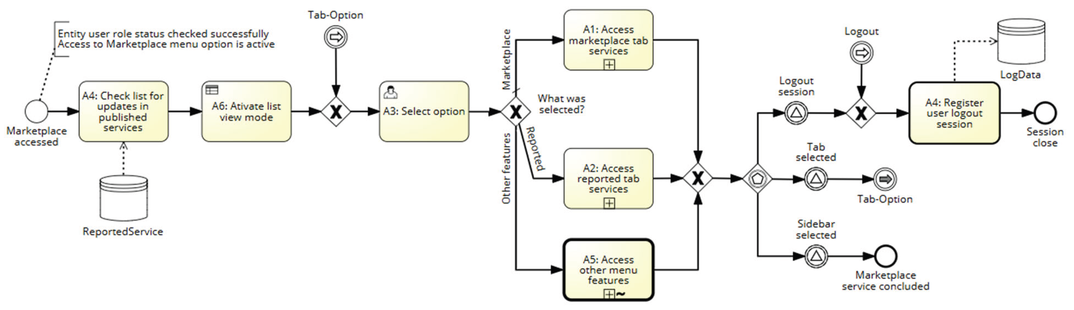
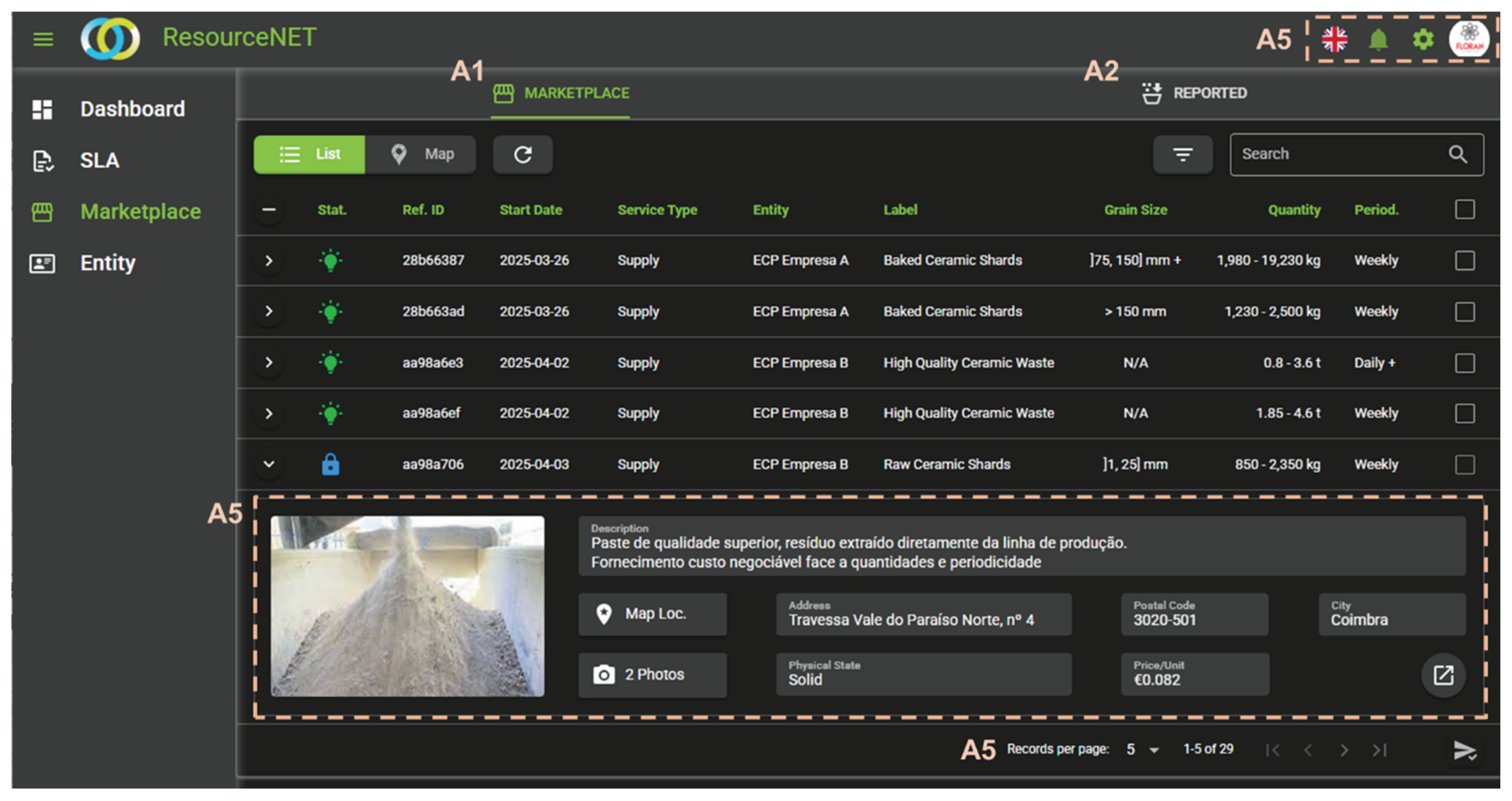
Figure 7 illustrates the graphical interface of the ResourceNet platform, which features a scrollable vertical sidebar providing direct access to its four main functional areas. This layout visually reflects the execution paths modeled in the BPD presented in Figure 6, which utilizes BPMN 2.0 notation to formally specify the workflow of the Marketplace module. The Marketplace section, selected as the primary use case for this paper, is functionally split into two subsections: the Marketplace tab, which presents all publicly available services published by registered entities (corresponding to subprocess A1 in Figure 6), and the Reported tab, which displays only the services created by users affiliated with the logged-in entity (mapped to subprocess A2). Transversal functionalities, such as account settings, language preferences, and alert configurations, are captured in subprocess A5 of the BPD.
The use of BPMN not only structures the functional behavior of the platform but also helps formalize non-functional requirements, particularly those related to information management. By explicitly modeling data artifacts (i.e., informational entities and their attributes) and their interaction with activities, BPMN supports traceability, data governance, and auditability, crucial aspects for platforms like ResourceNet that rely on trusted data exchange. Thus, the BPD in Figure 6 serves as a formal abstraction of the interface logic displayed graphically in Figure 7, aligning the system's visual presentation with its underlying process semantics.
Figure 7.
The graphical interface designed for the Marketplace service. A1) maps the Marketplace Tab subprocess, A2) maps the Reported Tab subprocess and A5) maps the corresponding subprocess, which is also a Call activity, meaning it can be reused in other processes.
Figure 7.
The graphical interface designed for the Marketplace service. A1) maps the Marketplace Tab subprocess, A2) maps the Reported Tab subprocess and A5) maps the corresponding subprocess, which is also a Call activity, meaning it can be reused in other processes.
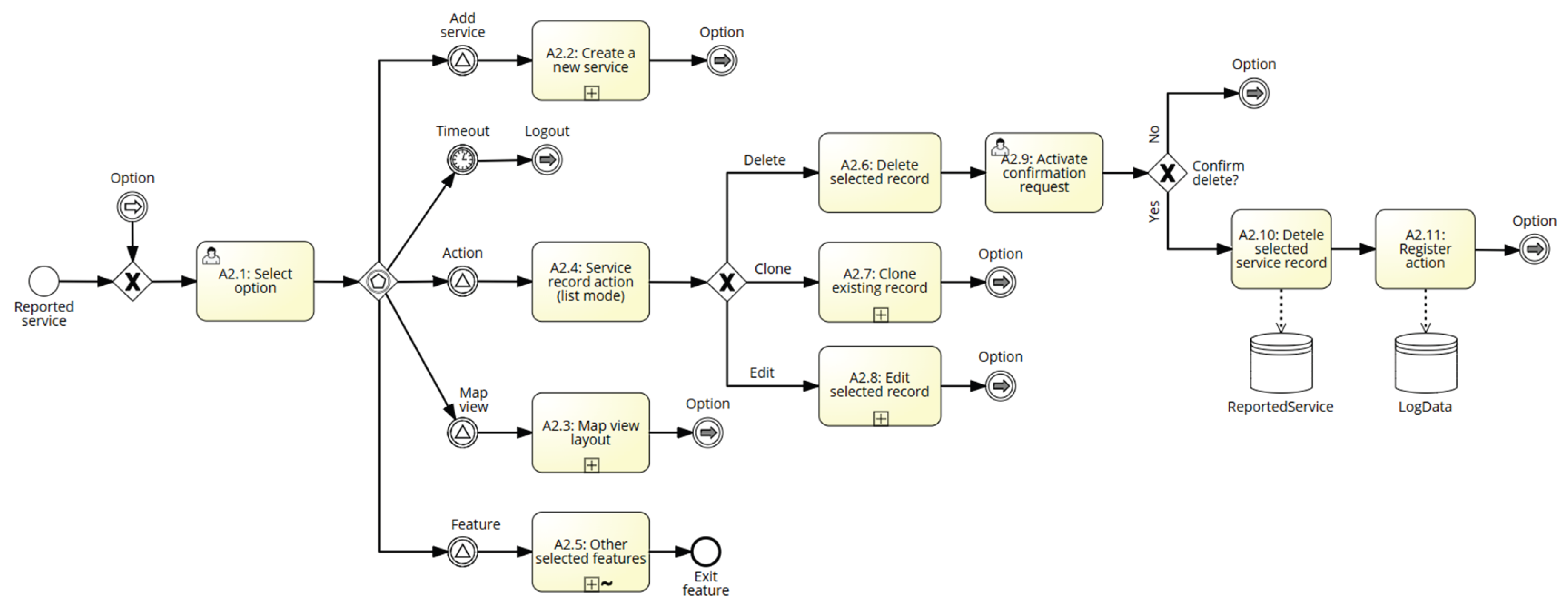
Access to the A2 subprocess is restricted to authorized users whose account status is set to Active. Account status transitions between Active and Blocked can be managed by privileged users with the roles of A-User, M-User, or O-User. Within the A2 subprocess (see Figure 8), the ResourceNet platform exposes a range of functional operations for managing reported services associated with the user's affiliated entity. Users can create a new service record from scratch using Activity A2.2, which involves completing a structured form that encompasses all required metadata attributes. Alternatively, the Clone operation (Activity A2.4) allows users to duplicate an existing service record, automatically assigning a new unique service ID. This significantly streamlines the creation process, as only selected fields need to be modified before submission, minimizing manual input while ensuring metadata consistency.
To manage existing services, users can select a record from the list and perform operations such as editing, deleting, or cloning. Editing enables updates to the service metadata, while deletion requires an explicit user acknowledgment due to audit and compliance policies. The deletion process triggers a specific sequence flow that includes Activities A2.10 and A2.11, ensuring traceability of user actions for accountability.
The A2.3 subprocess provides a geospatial visualization of services through a map-based interface, supporting typical interactive features such as panning, zooming in and out, and mouseovers. At lower map scales, services reported within the same location are aggregated and represented as a single geo-pin. As the user zooms in, these clusters are disaggregated, revealing individual service locations in the process. A List View toggle allows users to switch to a tabular layout for structured browsing.
The A2.5 subprocess, marked as ad-hoc, encapsulates additional dynamic features, such as toggling the visibility of reported services on the public Marketplace tab. This visibility control is especially relevant for services marked as Locked (i.e., already allocated to an active SLA and therefore not available for new partnerships). However, keeping Locked services visible allows the service owner to monitor ongoing interest from other entities. If new demand emerges, the Owner may choose to clone the Locked service to initiate a new SLA cycle. Furthermore, A2.5 integrates advanced filtering mechanisms, semantic search capabilities, and refresh controls to enhance the user experience when navigating and managing reported services. These functionalities support efficient information retrieval, contributing to the platform's overall responsiveness and usability.
Figure 8.
Business process diagram of the reported-tab service subprocess.
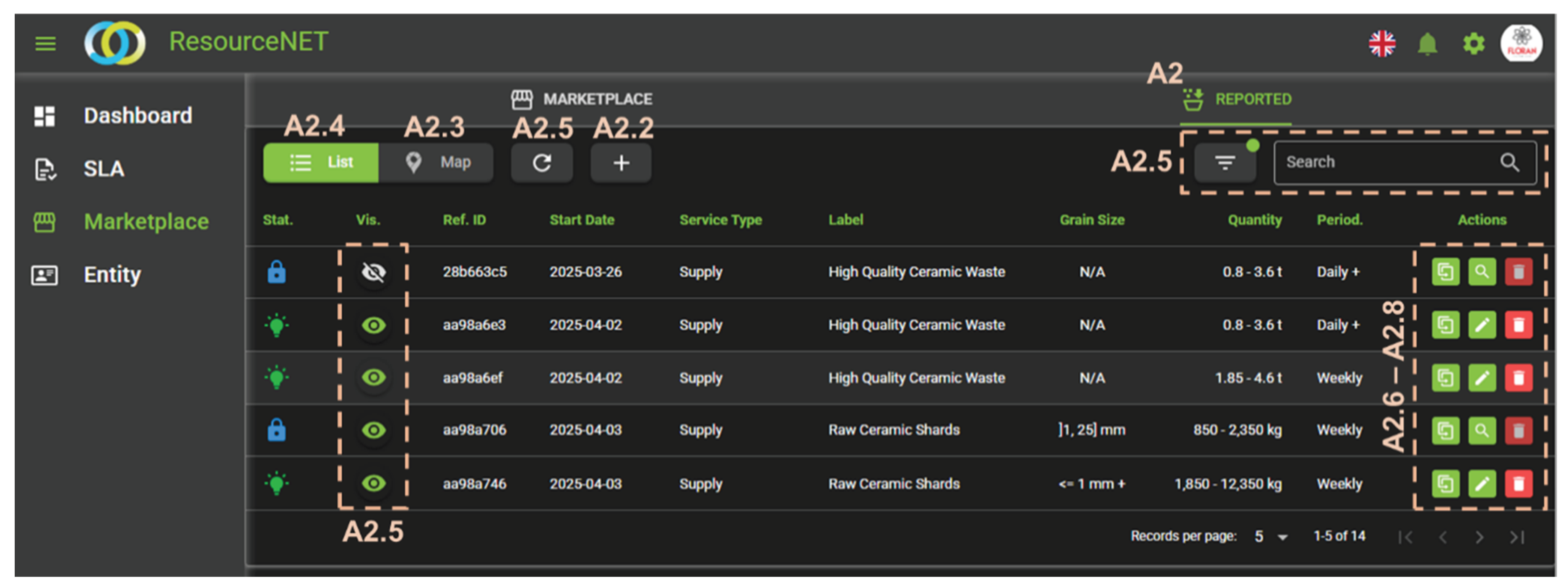
The GUI illustrated in Figure 9 reflects the formalized functional behavior specified in the BPD presented in Figure 8. This GUI serves as a visual counterpart to the modeled workflow, offering a layout that aligns user interactions with the underlying system functionality. Specifically, it represents the interface for the Reported Tab, which corresponds to execution paths defined in the BPMN diagram, including the List View and Map View modes (A2.4 and A2.3), the creation of a new service (A2.2), and record management operations such as delete, clone, and edit (A2.6–A2.8). The A2.5 subprocess aggregates several supporting interface functionalities within the workspace area, implemented as interactive buttons to enhance user interaction. These include:
 |
Reload Data: Synchronizes the client-side interface with the server to fetch and display the most up-to-date records. |
 |
Advanced Search: Allows users to customize filters by selecting which metadata attributes to include or exclude, improving information targeting and reducing interface clutter. |
 |
Visible/Hidden Toggle: Controls whether a service record is displayed on the Marketplace tab. This is key for records not in Active status (e.g., Locked), which are no longer available but may still attract interest for potential replication. |
 |
Semantic Search: Filters services based on keyword matching, enhancing information retrieval through context-aware search capabilities. |
 |
Audit Log Access: Grants authorized users the ability to view historical logs of changes to each record, supporting traceability and evidence-based analysis in case of disputes or system errors. |
These elements aim to simplify user interaction while maintaining logical consistency with the underlying BPMN model. The interface design not only facilitates the efficient execution of tasks but also translates modeled workflows into clear and accessible visual elements. This alignment significantly contributes to usability by promoting a coherent interaction flow, reducing user errors, and enhancing the recognizability of system features. The ability to switch between views, manipulate service records, or trigger subprocesses reflects a deliberate strategy to make the GUI self-descriptive, predictable, and easy to learn, particularly for recurring interactions.
Beyond supporting functional behavior, the ResourceNet platform's GUI was developed with a strong focus on non-functional quality requirements as defined in ISO 25010:2023. Usability, maintainability, and security are not treated as isolated goals but are interwoven to create a seamless user experience. For instance, by ensuring that graphical components are visually consistent across tabs and services, the platform enhances learnability and operability, while also simplifying future code updates, a relevant aspect for maintainability. Semantic search, audit traceability, and controlled visibility directly contribute to user empowerment and accountability, thereby increasing trust in the platform. The platform's error-prevention mechanisms and feedback cues further align with user error protection, while the audit log functionality enhances non-repudiation and traceability. These characteristics reinforce each other: usability increases when maintainability ensures consistency; Security becomes more robust when usability reduces errors and misuse; and maintainability is facilitated by a modular architecture built on reusable subprocesses. Together, these quality aspects form a tightly integrated foundation that improves not only system robustness but also the overall satisfaction and confidence of users interacting with the platform.
Figure 9.
Reported Tab GUI outlining the specified behaviour with graphical features for user interactions.
Figure 9.
Reported Tab GUI outlining the specified behaviour with graphical features for user interactions.
The BPD in Figure 10 outlines how Maintainability principles have been applied to the architectural design of the ResourceNet platform. A comparative analysis with previous BPDs reveals that most process activities are reused with minimal adjustments to accommodate service-specific functionalities. This reuse strategy yields consistent diagram structures, thereby enhancing readability and significantly reducing the cognitive load for the BizDevOps team. As a result, less time is spent interpreting process logic, allowing the team to focus on technical implementation details, such as identifying the relevant metadata to characterize a selected service, applying the appropriate business rules, or invoking Call Activities (e.g., A5 and A4) to ensure standard behavior across different use cases/user stories. The structural similarity also extends to the use of consistent gateway types and branching logic, particularly in the case of the SLA-related service, which, like the Marketplace, is organized into two tabs: Participant and Owner.
Furthermore, the familiarity of the sequence flows depicted in Figure 10, both for the development team and for business users, supports a streamlined modeling process. Rather than redesigning the entire workflow for each new service, the effort can be concentrated on modeling the elements that differ from the base case. This approach aligns with best practices in maintainable software design by promoting reuse, reducing duplication, and enabling modular development. As the foundational activities and control structures remain consistent, new scenarios can be incorporated efficiently, with changes isolated to the parts of the process that represent genuinely new functional or behavioral requirements. This not only accelerates development cycles but also reinforces system coherence, as common interactions and subprocesses maintain predictable behavior across the platform.
Figure 10.
Business process diagram of the SLA service.
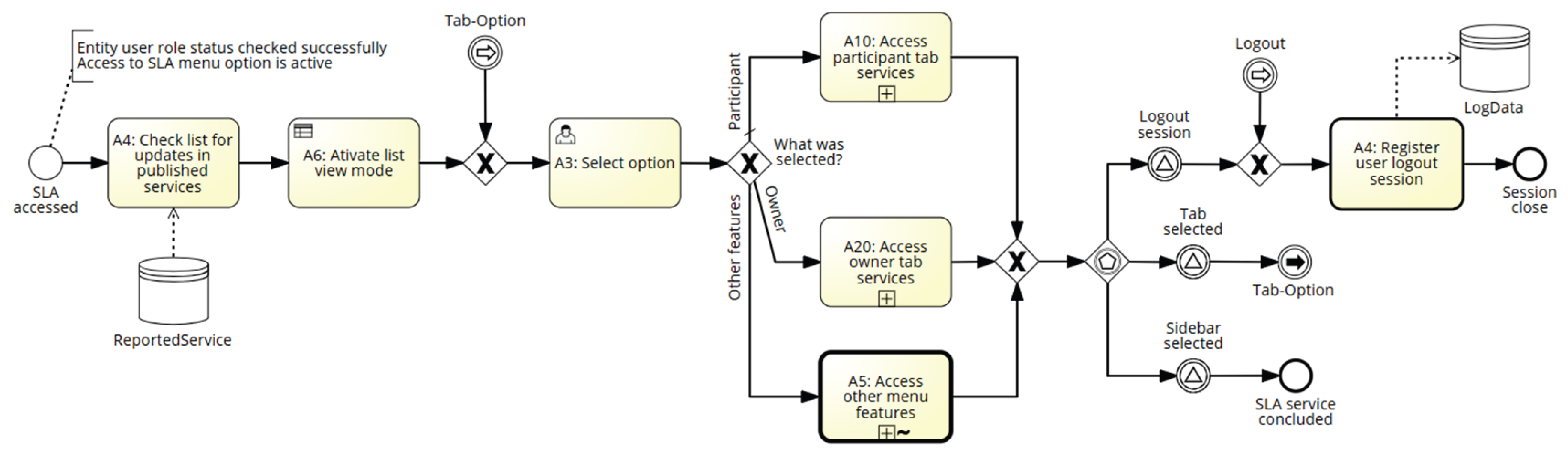
Figure 11 revisits the design pattern that links the BPD to its corresponding GUI, illustrating how the underlying process logic is materialized through interactive components in the user interface. These features represent the actionable, visible elements, such as icons, buttons, or links, that are activated when users engage with the platform, particularly within the SLA service context. They provide direct access to core functionalities, including visualizing the SLA lifecycle, monitoring status progression across defined stages, and identifying the number of entities involved in each SLA (Participants). The consistent design across different modules (evident in Figure 7, Figure 9, and Figure 11) fosters a coherent user experience by maintaining predictable interaction patterns and reinforcing usability. This approach aligns with the ISO 25010:2023 quality model, which defines characteristics like functional suitability, usability, maintainability, and security. Although the interface elements may appear similar to those used in other modules, the SLA service introduces metadata-specific variations, requiring the backend to handle distinct data structures and attributes. The uniform interface facilitates quicker identification of these particularities, enabling the development team to efficiently allocate functionalities to the appropriate modules and tailor the implementation according to the service-specific requirements.
When accessing a specific SLA record, the interaction model in the workspace area introduces significant modeling complexity due to the numerous possible user-driven pathways, each of which requires backend validation. The system must perform real-time server-side checks to confirm the current status of the SLA and its associated subSLAs, representing the participating entities. An additional layer of complexity arises when some subSLAs remain "On-hold", a status indicating that the invited entities have not yet responded to the SLA Owner's request. This distinction is critical because only the SLA Owner has visibility into the complete list of invited participants and their individual acceptance statuses. Participants, in contrast, are restricted to viewing only those who have already confirmed participation. This access control mechanism ensures the confidentiality and integrity of sensitive data flows, particularly in contexts governed by legal compliance frameworks, such as the Waste Declassification Directive, which oversees traceability and regulatory adherence in waste transportation procedures.
To ensure compliance with regulatory mandates, non-repudiation mechanisms are embedded within the SLA workflow. These mechanisms generate alerts for the SLA Owner and issue notifications to relevant Participants whenever irregular or suspicious activities are detected, thus supporting both auditability and accountability. In response to the branching complexity of possible actions within the SLA, the process model presented in Figure 12 replaces the previous gateway type with an Event-Based Gateway, which better accommodates dynamic, event-driven pathways. One such path, denoted as activity A20.6, supports the visualization of a supply chain dendrogram. This visual representation maps the digital logistics structure associated with the SLA, showing not only the contractual relationships between the SLA Owner and each Participant but also the interdependencies among Participants themselves. For example, the diagram may represent a scenario where one Participant supplies a SRM, another serves as the carrier responsible for transporting the SRM from its origin point to a processing site, and a third Participant receives and processes the SRM into a subproduct. This hierarchical view enhances traceability and supports the operationalization of complex, multi-actor service agreements.
3.3. Block Diagram - Architecture Description
This section introduces the architectural model of the ResourceNet platform, structured according to the MDA paradigm. The emphasis is placed on the block diagram, which abstracts the composition and interrelation of the core software modules across the platform's layered architecture. Rather than detailing exhaustive technical artifacts, such as the CRUD Matrix or the Traceability Matrix (omitted due to space limitations), this paper concentrates on describing the modular decomposition of the system. The architecture defines an open-access digital infrastructure designed to promote data exchange, enhance interoperability, and support collaborative dynamics among stakeholders in the ceramic sector. One of the platform's key objectives is to strengthen synergies between companies by facilitating information flows in a secure and controlled manner.
Interaction with external actors is facilitated via wireless API-based communication, which not only supports data exchange but also underpins the enforcement of data governance policies. This includes mechanisms for validating, filtering, and monitoring both incoming and outgoing data. As illustrated in Figure 13, these responsibilities are managed by the External Source Interoperability Framework module. This module functions as a dual-purpose component: externally, it acts as a gateway to integrate third-party systems, ensuring seamless interoperability; internally, it operates as a message broker that orchestrates communication among different services within the Business Logic layer. This architectural strategy ensures modular scalability, traceable data flows, and reliable communication pipelines aligned with the platform's openness and regulatory compliance requirements [24]. By encapsulating API-level interactions with third-party systems (e.g., Google Maps, external systems, regulators, etc.), the module also addresses the maintainability, testability, and modifiability requirements outlined in ISO 25010.
The Entity Metadata Manager module is responsible for processing registration data for both individual and collective entities, with particular emphasis on managing user associations within legal entities. It is structured into three core components: (1) Entity Registry, which handles entity identity attributes and maintains the list of affiliated users when the entity is classified as a "legal person"; (2) its integration with the User Register/Sign-In module, ensuring proper credential validation and access provisioning during entity registration workflows; and (3) Entity Data Management, responsible for handling administrative metadata and providing data management functionalities within the frontend layer. This module forms the foundational layer for enabling entity-centric service orchestration and access control.
The Marketplace Module processes data related to the registration and classification of services reported by authenticated and authorised users. It is organised into three components: (1) Service Data, which enforces business rules to validate the consistency and completeness of reported information before its publication in the Marketplace; (2) Reported Service, which links service instances to their respective reporting entities and ensures role-based compliance for services contributed by organisations; and (3) SLA Management, which governs the lifecycle of each SLA by orchestrating workflows from SLA initiation to closure. This includes integration with a matching algorithm to align service offers and demands, as well as managing state transitions and permissible user actions based on the SLA status, aligned with predefined business rules.
The Data Governance & Analytics module handles contextual, spatial, and regulatory aspects of SLA-related data flows. It is composed of: (1) (Geo)Context-Awareness, which processes georeferenced service data to trigger location-aware events and notifications; (2) Business Rules Management, which activates a state machine engine to enforce custom triggers and actions over entity, member, service, and SLA records based on evolving conditions; (3) SLA Supply Chain, which coordinates SLA governance across multiple entities with distinct roles in the value chain, ensuring traceability and compliance; and (4) KPI Manager, a component that allows users to define, compute, and track performance indicators over time through embedded analytics. Although the presentation layer is not addressed in this article, it's worth mentioning the Entity Interactive Dashboard, a visual analytics interface featuring scorecards for monitoring SLA and service KPIs. A scorecard is a graphical interface that displays a collection of metrics (goals or KPIs), each with associated status, targets, progress, and trends. It allows organisations to track progress against strategic or operational objectives over time. The software modules at the presentation layer provide a responsive web interface that dynamically adjusts based on the user's access profile and the device screen's characteristics (e.g., 15" screen or 8" screen).
Figure 13.
Block diagram of the architecture approach.
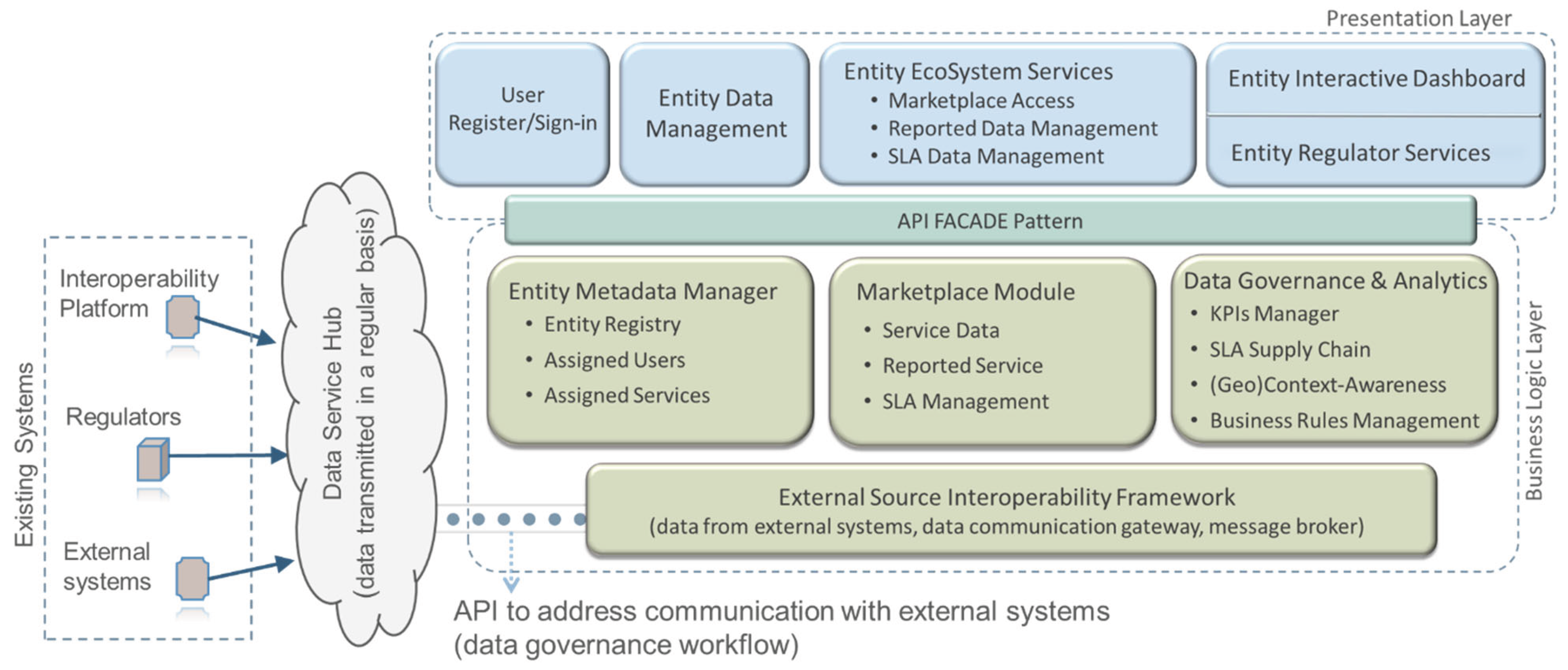
The frontend layer of the ResourceNet platform offers a role-based access to services and data through interactive interfaces. It includes user registration and sign-in workflows that ensure secure access, complying with ISO 25010 usability and security criteria. The Interactive Dashboard presents SRM management indicators and SLA workflows using visual components, such as scorecards and dendrograms, to enhance the operability and aesthetic appeal of the interface. The Entity Regulator Services interface enables the O-User to oversee platform membership and validate new entity registrations. Depending on user roles (e.g., A-User, M-User, S-User), access levels and visualised content are tailored, supporting contextual awareness and decision-making while ensuring alignment with usability, accessibility, and traceability requirements.
To manage the complexity of subsystem interactions, the architecture incorporates the Facade design pattern [25], which introduces a unified structural interface that abstracts the internal workings of the system, thereby simplifying its overall structure. This design choice allows clients to interact with the platform through a simplified access point, without requiring knowledge of the underlying logic or internal dependencies. The use of the Facade pattern is particularly effective in environments composed of multiple tightly coupled classes, as it helps to decouple clients from complex subsystems, thereby increasing modularity and improving the platform's maintainability.
4. Discussion
This paper addresses a challenge in contemporary software engineering: aligning rapidly evolving business needs with adaptable and traceable software architectures. The research lies in reconciling the dynamic nature of business processes with the rigidity often encountered in traditional software architectures. In the context of digital circular economy platforms, such as the ResourceNet marketplace for SRMs, systems must be both adaptable and compliant with stringent regulatory frameworks, including the European Union's Waste Declassification Directive, as well as the broader objectives of the Circular Economy Action Plan. The proposed dual-framework approach, combining MDA and PDA, offers a novel solution that enables software systems to remain responsive to evolving business needs while ensuring traceability, scalability, and compliance.
The architectural framework innovation presented in this paper, as illustrated in Figure 2, stems from the structured integration of MDA and PDA under the guidance of ISO 42010:2022. MDA enables the formalization of system structure and behavior through modular block diagrams, UML class and component models, and CRUD matrices. These models define internal architecture and data responsibilities across presentation, business logic, and data layers. PDA, on the other hand, emphasizes operational logic and user interactions, leveraging BPMN as standardized in ISO 19510:2013. Through hierarchical modeling, from value chain overviews to Level 4 executable workflows, PDA captures business intent, stakeholder responsibilities, and compliance constraints in visual, traceable artifacts.
This combination of formal modelling techniques (e.g., BPMN and UML) enables the explicit visual representation of both process logic and software structure. In particular, BPMN diagrams define the flow of tasks, events, and decision points in business operations. In contrast, UML class, component, and service diagrams provide clarity on data models and system interactions. This layered modelling supports traceability from stakeholder concerns to software functionalities, helping ensure the integrity, usability, and maintainability of the final system. The requirements specifications are accompanied by a set of iterative phases that improve their accuracy and quality, as defined in ISO 25010:2023.
The ResourceNet case study exemplifies how this architectural approach can be operationalized to meet real-world regulatory, functional, and stakeholder requirements. This layered modeling approach has proven particularly effective in the ResourceNet platform, where multilevel workflows govern data submission, service reporting, SLA negotiation, and compliance verification. By aligning BPMN activities with backend logic and service orchestration, the system ensures that each functional requirement is mapped to a tangible implementation unit [26]. For example, user-facing activities, such as "Report an Issue" or "Submit SRM," are tied to GUI components validated against ISO 25010:2023 usability and security criteria. Meanwhile, backend activities, including "Marketplace service report" or "Trigger SLA Matching," are implemented through deterministic APIs with audit-capable traceability.
The case study demonstrates that the combined MDA-PDA framework improves alignment between software architecture and stakeholder concerns. Stakeholders, including SRM providers, carriers, processors, regulators, and platform administrators, all have distinct viewpoints and expectations. These were explicitly modeled in the ResourceNet context diagram and stakeholder table, establishing traceability between user roles and architectural elements. By following the viewpoint-based methodology outlined in ISO 42010:2022, each concern, whether related to compliance, data access, performance, or usability, is addressed through corresponding structural or behavioral models.
Concrete research findings from the ResourceNet prototype highlight the practical value of this architecture. For instance, using BPMN Level 3 and Level 4 diagrams, the SLA module orchestrates complex service agreements involving multiple actors, each with access restrictions, status-dependent behaviors, and customized user experiences. Activities such as service submission, SLA invitation, and partner confirmation are all governed by predefined business rules and visualized through BPMN diagrams (Figure 6, Figure 11, and Figure 12). These workflows directly map to backend services via MDA-defined modules, ensuring consistency between design and implementation. Specific components, such as the External Source Interoperability Framework and Entity Metadata Manager, illustrate how APIs and metadata services can be coordinated to support both human and machine actors, thereby improving system responsiveness and integration flexibility.
The integration of a Data Governance Framework (DGF) into the PDA lifecycle is another significant contribution. It ensures that data handling, especially in contexts involving sensitive or geospatial data, is aligned with both technical specifications and regulatory mandates. The framework governs data ingestion, metadata management, and access control in line with user roles and business rules, ensuring compliance with data privacy and integrity mandates. BPMN task types—user tasks, service tasks, and business rule tasks—are used to classify how data is captured and processed, linking business logic to backend behaviour in a transparent and accountable way. The auditing mechanism, built to align with the AAA protocol, ensures that all actions are tracked, further supporting regulatory compliance [27].
Another compelling outcome of the ResourceNet initiative is its ability to align software functionalities with stakeholder concerns, particularly in a multitenant ecosystem. Various stakeholder profiles (e.g., industry actors, carriers, processors, and regulatory authorities) are mapped to platform roles (A-User, M-User, S-User, R-User, and O-User), each with defined permissions and responsibilities. This role-based model ensures that the platform enforces data visibility rules, guarantees operational separation of concerns, and supports transparency in decision-making processes.
Despite the observed benefits, the research also highlights several challenges. First, the absence of a universally accepted methodology for integrating MDA and PDA into agile lifecycles presents difficulties in tooling and process orchestration. While Figure 2 provides a structured sequence for architectural modeling, further work is needed to standardize the evolution of process artifacts (BPMN) into deployable code or testable specifications. Second, managing modularity and traceability across multiple BPMN levels, especially when workflows become deeply nested, requires disciplined model versioning and robust documentation practices. Lastly, in multitenant scenarios, ensuring consistent quality of service across highly variable configurations remains an open issue, requiring more advanced runtime adaptation mechanisms. Furthermore, given the rise of AI-driven analytics and real-time process monitoring, the architectural framework must evolve to incorporate continuous data feedback loops and support autonomous decision-making mechanisms without compromising traceability or auditability.
Future work should explore automation strategies for synchronizing PDA models with MDA diagrams and runtime artifacts, using model transformation tools or low-code platforms. Additional research could also investigate performance implications of BPMN-executed workflows at scale, and how MDA-PDA alignment can be optimized in serverless or microservices-based deployments [28]. Future work will also focus on expanding the use of decision modelling techniques, such as DMN, to externalize business logic and ensure modularity and maintainability in the face of changing regulatory rules. Additional emphasis will be placed on improving interoperability with open data platforms, aligning with the European Open Science Cloud (EOSC) [29] and the INSPIRE directives [30], to enhance the sharing of semantic metadata and service discoverability across sectors.
5. Conclusions
The paper presented a dual architectural strategy that integrates MDA and PDA under the guidance of ISO 42010:2022. The combined approach provided a structured and traceable methodology for developing complex, stakeholder-aligned software systems. Grounded in real-world application, the ResourceNet platform served as a case study to validate the feasibility of this architecture in operationalizing the digital supply chain of SRM within the ceramics sector. It was explained that the ISO 42010:2023 standard frames system architecture as a formal representation of a system's fundamental properties within its environment. This includes the system's elements, relationships, and the guiding principles that shape its design and evolution. The standard provides a foundation for defining the system's internal structure (its components and their properties), the interactions between these components (system behaviour), and distinct perspectives that illustrate different aspects of the system tailored to stakeholder needs.
At its core, the main innovation of the proposed architectural framework lies in the synergistic integration of MDA and PDA as complementary architectural patterns. MDA offers system modularity through layered representations (e.g., context and block diagrams), helping define internal system structures and relationships between modules. PDA brings dynamic business process modeling into the software lifecycle through BPMN-based workflows that represent executable activities, decisions, and data exchanges. By unifying both perspectives within a BizDevOps workflow, the development process becomes more responsive to user needs, enabling continuous stakeholder collaboration and early validation of system behaviors.
In line with the ISO 19510:2013 and ISO 25010:2023 standards, the ResourceNet implementation utilized BPMN and UML notations to articulate both functional and non-functional requirements, thereby improving traceability, usability, and maintainability. BPMN tasks were mapped to backend services and APIs, while UML diagrams captured system components and class behaviors, ensuring consistency across process and software views. This clarity was essential for modeling service-level agreements (SLAs), user interactions, and audit mechanisms, particularly in regulatory contexts. The case study highlighted the architectural alignment between system functionality and stakeholder concerns, notably for industry actors, processors, carriers, and regulatory authorities. These stakeholder perspectives were explicitly modeled in the context and process diagrams, which guided the architectural decomposition and informed data governance strategies. The platform's support for real-time messaging, role-based access control, and traceable data pipelines reinforces its suitability as an enabler for cross-sector collaboration and a digital circular economy.
Research findings also demonstrate that the use of context diagrams (Level 0) facilitates early identification of external actors and interactions, setting the foundation for system boundaries and integration points. At Levels 1 and 2 of the PDA landscape, high-level value chain diagrams were employed to organize business macroprocesses as Black Boxes, allowing stakeholders to focus on interdependencies and service orchestration rather than implementation detail. Levels 3 and 4 further refined these workflows into executable BPMN models, connecting each activity to a functional requirement and clarifying data governance constraints at the process level.
The proposed architectural approach offers a replicable model for building agile, standards-compliant platforms in regulated, data-intensive domains. The ResourceNet platform exemplifies how formal architectural frameworks can be applied to achieve sustainability, traceability, and operational innovation in real-world circular economy initiatives.
Funding
Green Agenda for Business Innovation, financed by the RRP - Recovery and Resilience Plan, within the scope of the European Union's Next Generation EU | Project nº 76.
Institutional Review Board Statement
Not applicable.
Informed Consent Statement
Not applicable.
Data Availability Statement
The data presented in this study are available in this article and supplementary material.
Conflicts of Interest
The authors declare no conflict of interest.
Appendix A. BPMN Core Elements and Symbols
The primary purpose of BPMN is to create clear and understandable business process flowcharts, serving as a common language for stakeholders. It visually represents process steps, aiding comprehension for business users and facilitating improvements in decision-making and situational awareness. It bridges gaps in business process management stages, fostering collaboration among stakeholders. As a standard process modelling language, BPMN uses various symbols and elements, detailed in Table A1, to depict process aspects.

Table A1.
Core modelling elements depicted by the notation.
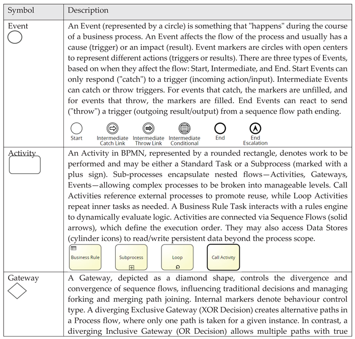 |
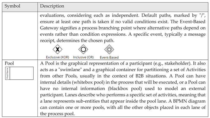 |
References
- Z. Jwaida, A. Dulaimi, and L. F. A. Bernardo, “The Use of Waste Ceramic in Concrete: A Review,” CivilEng, vol. 5, no. 2, pp. 482–500, May 2024. [CrossRef]
- H. M. Magbool, “Utilisation of ceramic waste aggregate and its effect on Eco-friendly concrete: A review,” Journal of Building Engineering, vol. 47. 2022. [CrossRef]
- K. Kalaboukas, D. Kiritsis, and G. Arampatzis, “Governance framework for autonomous and cognitive digital twins in agile supply chains,” Comput. Ind., vol. 146, Apr. 2023. [CrossRef]
- J. Kirchherr, N. H. N. Yang, F. Schulze-Spüntrup, M. J. Heerink, and K. Hartley, “Conceptualizing the Circular Economy (Revisited): An Analysis of 221 Definitions,” Resour. Conserv. Recycl., vol. 194, p. 107001, Jul. 2023. [CrossRef]
- G. Pestana, M. Almeida, and N. Martins, “Tracking Secondary Raw Material Operational Framework—DataOps Case Study,” Ceramics, vol. 8, no. 1, Mar. 2025. [CrossRef]
- M. Fugazzotto et al., “Industrial Ceramics: From Waste to New Resources for Eco-Sustainable Building Materials,” Minerals, vol. 13, no. 6, 2023. [CrossRef]
- M. Panigrahi, R. I. Ganguly, and R. R. Dash, “Applications, challenges and opportunities of industrial waste resources ceramics,” in High Electrical Resistance Ceramics - Thermal Power Plant Waste Resources, 2023. [CrossRef]
- K. A. Oliveira et al., “Ceramic shell waste valorization: A new approach to increase the sustainability of the precision casting industry from a circular economy perspective,” Waste Manag., vol. 157, 2023. [CrossRef]
- R. E. Bueno, M. N. Pohlmann, H. A. dos Santos, and R. F. Gonçalves, “The Procurement 4.0 Contributions to Circular Economy,” Sustain., vol. 16, no. 14, Jul. 2024. [CrossRef]
- Presidency of the Council of Ministers, “Decree Law No. 102-D/2020 | DR,” Republic Diary No. 239/2020, Series 1 of 2020-12-10, 2020. [Online]. Available: https://diariodarepublica.pt/dr/en/detail/decree-law/102-d-2020-150908012. [Accessed: 18-Jul-2025].
- European Environment Agency, “The Waste Framework Directive 2008/98/EC in Portugal ,” 2022.
- J. dos S. Silva and M. S. A. Leite, “Analysis of a supply chain in the ceramic sector: a look at business processes,” Gestão & Produção, vol. 31, 2024. [CrossRef]
- Kleopatra CHASIOTI and Chris MANADIS, “BizDevOps: A process model for the Alignment of DevOps with Business Goals,” 2019.
- Object Management Group (OMG), “Model Driven Architecture (MDA) | Object Management Group,” 2025. [Online]. Available: https://www.omg.org/mda/. [Accessed: 18-Jul-2025].
- T. Ahmad and A. Van Looy, “Business Process Management and Digital Innovations: A Systematic Literature Review,” Sustain. 2020, Vol. 12, Page 6827, vol. 12, no. 17, p. 6827, Aug. 2020. [CrossRef]
- Bucaioni, A. Di Salle, L. Iovino, and P. Liang, “Model-driven engineering for Software Architecture,” J. Syst. Softw., vol. 223, May 2025. [CrossRef]
- F. Strnadl, “Aligning Business and It: The Process-Driven Architecture Model,” Inf. Syst. Manag., vol. 23, no. 4, pp. 67–77, Sep. 2006. [CrossRef]
- J. N. Korongo, S. T. Mbugua, and S. M. Mbuguah, “A Review Paper on Application of Model-Driven Architecture in Use-Case Driven Pervasive Software Development,” Int. J. Comput. Trends Technol., vol. 70, no. 3, pp. 19–26, Mar. 2022. [CrossRef]
- Drave, J. Michael, E. Müller, B. Rumpe, and S. Varga, “Model-Driven Engineering of Process-Aware Information Systems,” SN Comput. Sci., vol. 3, no. 6, Nov. 2022. [CrossRef]
- S. I. Ahmad, T. Rana, and A. Maqbool, “A Model-Driven Framework for the Development of MVC-Based (Web) Application,” Arab. J. Sci. Eng., vol. 47, no. 2, pp. 1733–1747, Feb. 2022. [CrossRef]
- G. Polančič and K. Kous, “High-Level Process Modeling—An Experimental Investigation of the Cognitive Effectiveness of Process Landscape Diagrams,” Math. 2024, Vol. 12, Page 1376, vol. 12, no. 9, p. 1376, Apr. 2024. [CrossRef]
- S. Nadal, P. Jovanovic, B. Bilalli, and O. Romero, “Operationalizing and automating Data Governance,” J. Big Data, vol. 9, no. 1, p. 117, Dec. 2022. [CrossRef]
- Paolini, D. Scardaci, N. Liampotis, V. Spinoso, B. Grenier, and Y. Chen, “Authentication, authorization, and accounting,” Lect. Notes Comput. Sci. (including Subser. Lect. Notes Artif. Intell. Lect. Notes Bioinformatics), vol. 12003, pp. 247–271, 2020.
- N. Martin, “Overview of the Revised Standard on Architecture Description – ISO/IEC 42010,” INCOSE Int. Symp., vol. 31, no. 1, pp. 1363–1376, Jul. 2021. [CrossRef]
- N. D. Kulkarni and S. Bansal, “Utilizing the Facade Design Pattern in Practical Phone Application Scenario,” J. Artif. Intell. Cloud Comput., pp. 1–5, Mar. 2022. [CrossRef]
- I. Torre-Bastida, G. Gil, R. Miñón, and J. Díaz-de-Arcaya, “Technological Perspective of Data Governance in Data Space Ecosystems,” in Data Spaces, Cham: Springer International Publishing, 2022, pp. 65–87. [CrossRef]
- G. Pestana and S. Sofou, “Data Governance to Counter Hybrid Threats against Critical Infrastructures,” Smart Cities, vol. 7, no. 4, pp. 1857–1877, Jul. 2024. [CrossRef]
- Fritzsch, J. Bogner, M. Haug, S. Wagner, and A. Zimmermann, “Towards an Architecture-Centric Methodology for Migrating to Microservices,” Lect. Notes Bus. Inf. Process., vol. 489 LNBIP, pp. 39–47, 2024. [CrossRef]
- EOSC, “European Open Science Cloud (EOSC) - European Commission,” European Commission, 2025. [Online]. Available: https://research-and-innovation.ec.europa.eu/strategy/strategy-research-and-innovation/our-digital-future/open-science/european-open-science-cloud-eosc_en. [Accessed: 21-Jul-2025].
- INSPIRE, “INSPIRE Knowledge Base,” European Commission, 2021. [Online]. Available: https://knowledge-base.inspire.ec.europa.eu/overview_en. [Accessed: 21-Jul-2025].
Figure 2.
Overview of the proposed architectural approach.
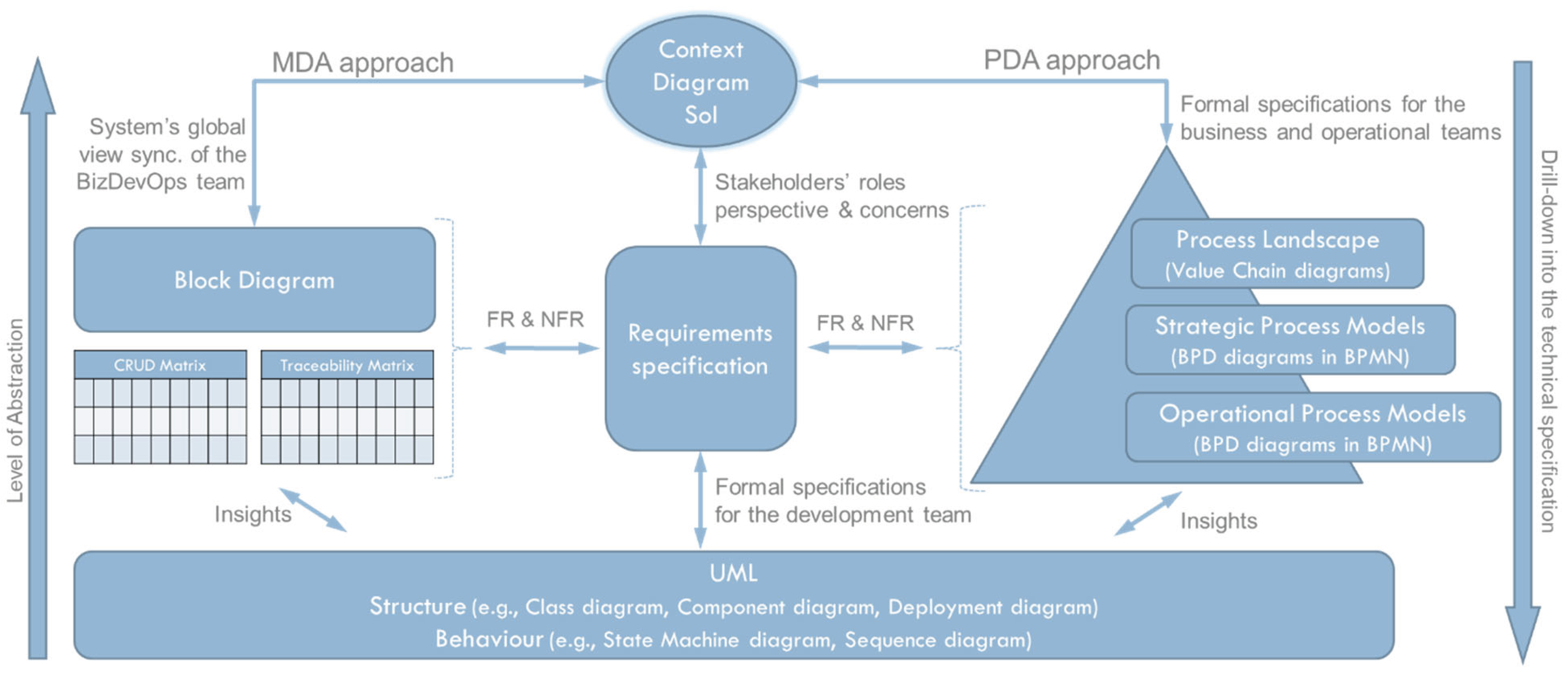
Figure 3.
Technical Overview of the PDA Landscape (source Signavio - https://shorturl.at/e85W3) In the context of Signavio, the process lifecycle, structured into levels, typically refers to a hierarchical framework for modeling and analyzing business processes, used to organize and interpret process structures within an organization systematically.
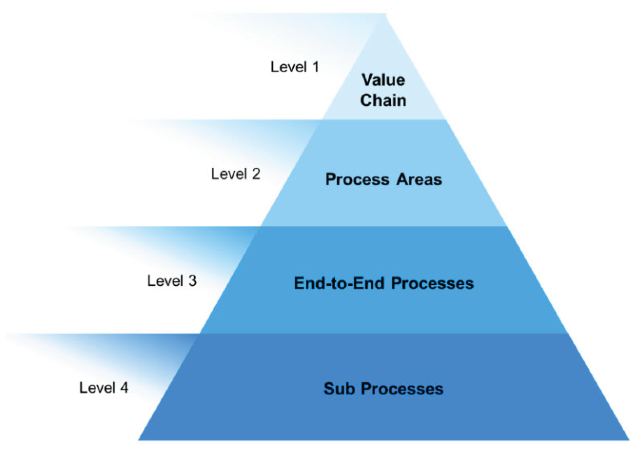
Figure 5.
Context diagram of the supply chain for secondary raw materials.
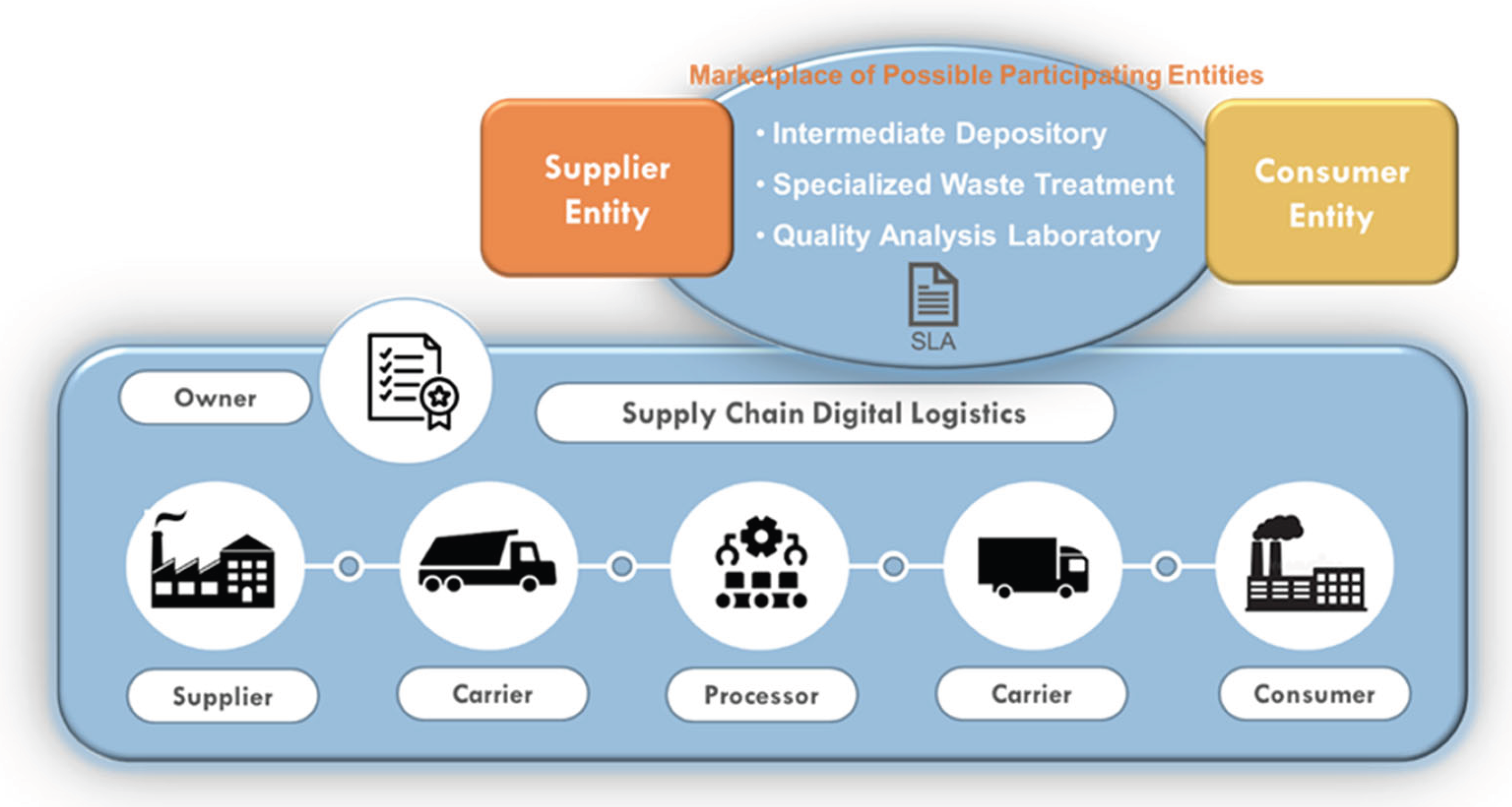
Figure 11.
The interface of the two services provided for the SLA service. 1) Participant Tab GUI and 2) Owner Tab GUI outlining the specified behaviour with graphical features for user interactions.
Figure 11.
The interface of the two services provided for the SLA service. 1) Participant Tab GUI and 2) Owner Tab GUI outlining the specified behaviour with graphical features for user interactions.
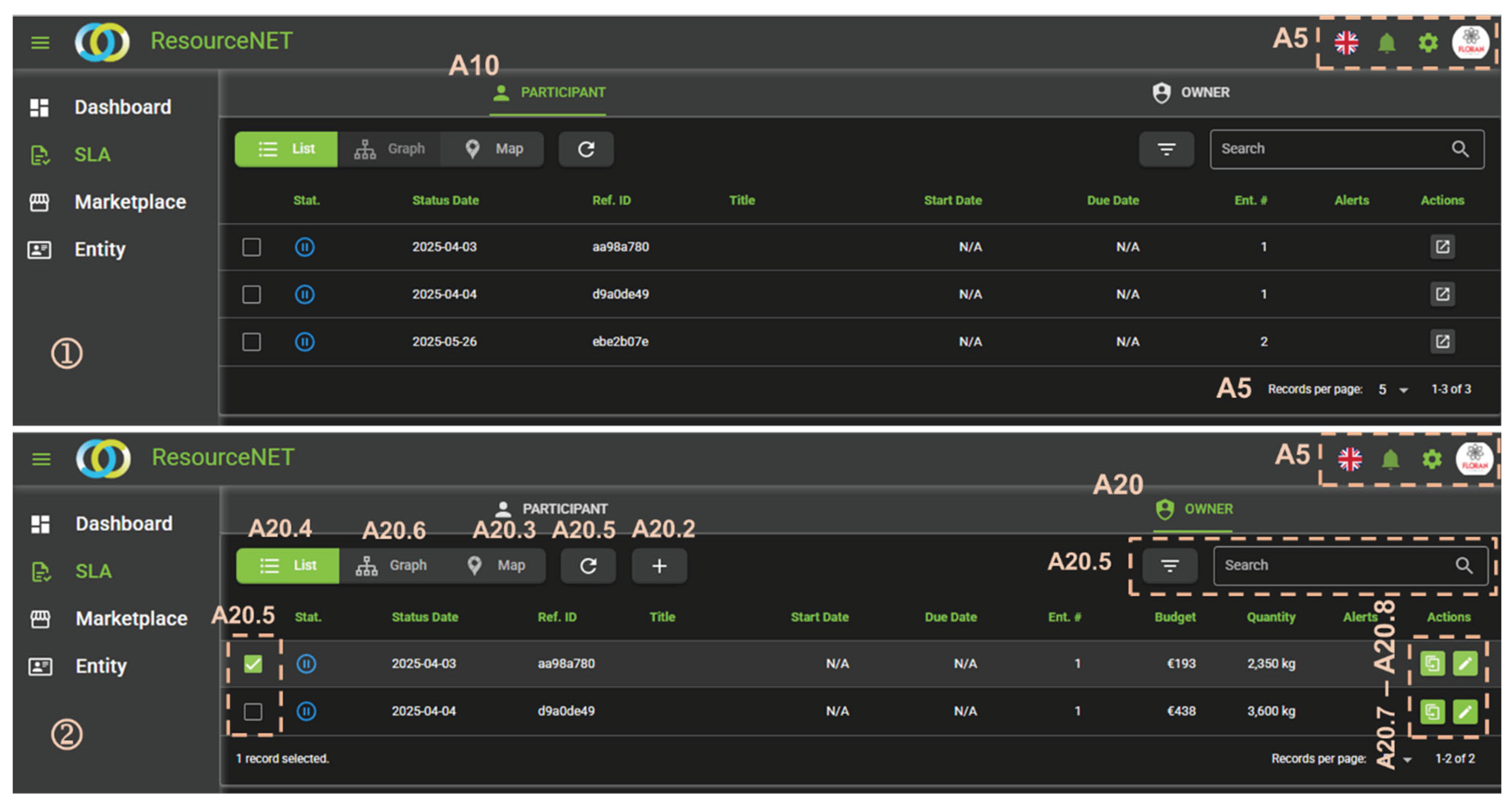
Figure 12.
Business process diagram of the sub-process owner-tab service.
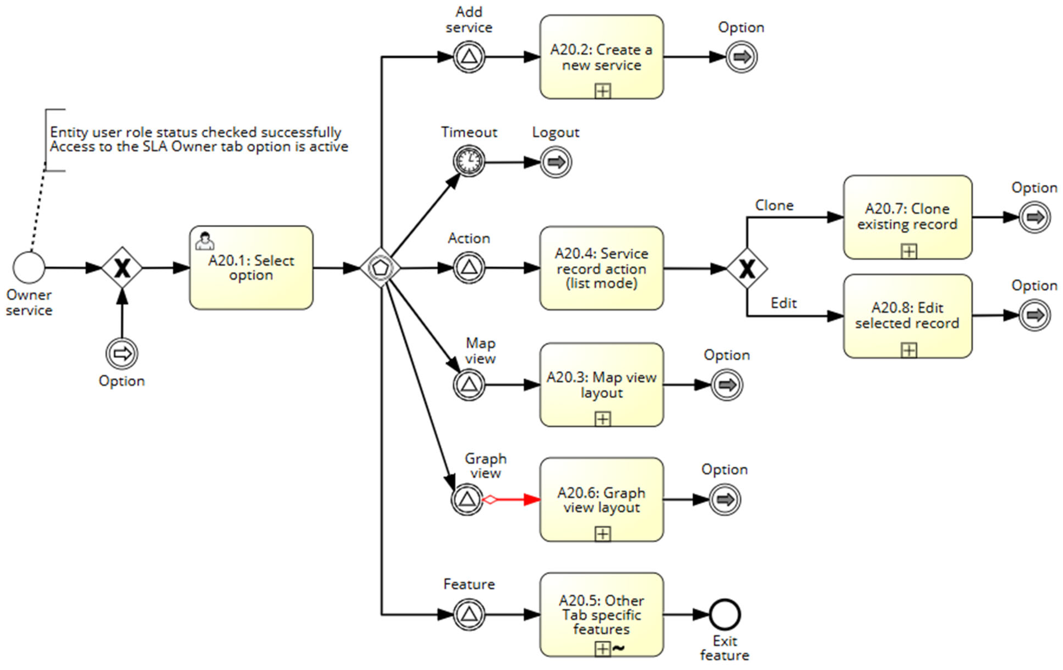
Table 1.
Stakeholders' distinct perspectives are shaped by their roles.
| Stakeholder | Entity Role and Type of Interest in the System |
|---|---|
| Industry | Role: When reporting an SRM service, an entity can either report a specific need (C—consumption) or provide an availability (S—supply). It can be involved in establishing an SLA. Type of interest: Direct interest and possible promoter of actions to establish a commercial partnership. |
| Carrier | Role: An entity that operates at the level of SRM transport and may simultaneously be an industrial partner. It can be involved in establishing an SLA. Type of interest: Indirect interest |
| Processor | Role: An entity that processes SRM materials by grinding them to the necessary/specified granulometry requested by the consumer entity. It can be involved in establishing an SLA. Type of interest: Indirect interest |
| Intermediate Depositor | Role: An entity that operates solely as a temporary storage for SRM (without processing capacity). It can be involved in establishing an SLA. In some cases (e.g., when the SRM is classified as waste requiring specific treatment), the entity may need to be a specialized waste treatment and eco-recycling center. Type of interest: Indirect interest |
| Quality Analysis Laboratory | Role: An entity that performs analyses on the composition of SRM, identifying potential risk substances that may compromise the quality of the by-product or its intended use. Typically, this is a service contracted by an industry entity. Type of interest: Indirect interest |
| Owner | Role: An entity that manages the ResourceNet platform, ensuring the integrity of membership applications. Responsible for ensuring that community members use the platform as intended, avoiding situations that could compromise transparency or business requirements relevant to the sector. Has the authority to change the registration status of an entity if non-compliance is detected. Type of interest: Indirect interest, but a regulator of ethical behavior compliance within the community |
Disclaimer/Publisher’s Note: The statements, opinions and data contained in all publications are solely those of the individual author(s) and contributor(s) and not of MDPI and/or the editor(s). MDPI and/or the editor(s) disclaim responsibility for any injury to people or property resulting from any ideas, methods, instructions or products referred to in the content. |
© 2025 by the authors. Licensee MDPI, Basel, Switzerland. This article is an open access article distributed under the terms and conditions of the Creative Commons Attribution (CC BY) license (https://creativecommons.org/licenses/by/4.0/).
Copyright: This open access article is published under a Creative Commons CC BY 4.0 license, which permit the free download, distribution, and reuse, provided that the author and preprint are cited in any reuse.


