Submitted:
19 July 2025
Posted:
22 July 2025
Read the latest preprint version here
Abstract
Background and Objectives:
Using lipid nanocarriers to deliver the mRNA of a specific antigen to immune cells is a powerful new approach to rapidly develop new safe and effective vaccines. Understanding and optimizing the mixing process necessary for mRNA lipid nanoparticles (LNP) is the focus of this review. The first objective is to review the fundamentals of fluid mixing process needed to understand the basic nanoparticle self-assembly process. Then some important experimental nanoparticle studies which are the basis for the current understanding of LNP mixing process will be reviewed. Finally, the current commercially available LNP mixing technology will be summarized.
Results:
LNP formulation by solvent-exchange mixing requires reducing the fluid homogenization time, t_mix , to significantly below the time required for the nanoparticle to self-assembly. Reducing t_mix is accomplished by reducing the striation length l_st of the mixing streams to allow for “rapid” molecular diffusion between the fluid streams. The two most popular passive fluid mixing conditions for reducing l_st are chaotic advection and turbulence.
Conclusions:
There appears to be no universally “best” mixing process for formulating nanoparticle or mRNA LNP. Both, chaotic advection and turbulent flow microfluidic mixing devices using the proper parameters for each device will formulate similar mRNA LNP vaccines during development. However, the low fluid output of microfluidic devices may not be practicable at higher fluid flow rates. Larger scale turbulent mixing devices are more suitable for clinical scale mRNA LNP production.
Keywords:
nanoparticle
; vaccines
; mRNA
; LNP
; microfluidic
; turbulent
1. Introduction
Small molecule agonists or antagonists to specific sites on specific enzymes or receptors have been the primary focus of pharmaceutical activity in the 20th century. The delivery of these bioactive molecules to cellular sites is typically accomplished by passive diffusion and permeation of membranes. The medical opportunities in the 21st century demand moving beyond inefficient non-targeted passive delivery of small bioactive molecules. These new medical opportunities require in vivo controlled release of small bioactive molecules and intracellular delivery of unstable biomolecules such as plasmid DNA (pDNA), small interfering RNA (siRNA), and messenger RNA (mRNA). These 21st century demands require the development of nanocarriers for delivery of both bioactive molecules and vaccines. This has resulted in an explosion of biocompatible nanoparticle research, development, and clinical application. Controlled slow in vivo release of small bioactive molecules is the application of many long acting injectable (LAI) nanoparticle formulations. Formulation of biocompatible nanoparticles for therapeutic LAI is outside the scope of this review[1,2].
The primary focus will be on fluid mixing technology used to formulate lipid nanoparticles (LNP) to encapsulate nucleic acids such as pDNA, siRNA, and mRNA. The emphasis of this review will be on fluid mixing issues related to mRNA LNP formation because of the high importance of mRNA LNP vaccine development at this time. A full evaluation of all aspects of mRNA LNP vaccine efficacy and safety is beyond the scope of this review. Our definition of nanoparticles will be an aqueous suspension of self-assembled” biomolecule particles with a weight-averaged diameter in the 10 to 500 nm range. “Self-assembly” is a process in which a disordered system of pre-existing components form an organized structure or pattern because of specific, local interactions among the components themselves, without external direction [3]. The level of structural organization is enough in the nanoparticle to maintain a thermodynamically stable diameter. Even so, individual biomolecules within the structure may not be highly organized relative to each other. Natural nanoparticle self-assembly is essentially the process responsible for producing macromolecular structures within all living cell such cell membranes, and ribosomes [4]. Even protein folding itself can be considered a form of self-assembly[5]. Pharmaceutical scientist have used controlled self-assembly to prepare therapeutically efficacious nanoparticles for drug delivery[6], medical diagnostic and imaging[7], vaccine antigen[8] , and vaccine adjuvant[9] delivery.
Lipid nanoparticle (LNP) formulation methods involve self-assembly of lipids and nucleic acids. This review will focus on the solvent / antisolvent mixing self-assembly method which has been used to prepare liposomes, oil-water emulsions, and many various LNP formulations [10]. The two FDA approved COVID-19 mRNA LNP vaccines were formulated by solvent /antisolvent mixing self-assembly [11,12]. This liposome and LNP self-assembly process typically requires a critical rapid mixing step where a miscible organic solvent stream (solvent) with dissolved hydrophobic lipid molecules and aqueous stream (anti-solvent) with water soluble molecules are combined. Mixing self-assembly occurs when the hydrophobic lipid molecules get rapidly solvent exchanged into a more hydrophilic mixed solvent. This causes the lipid molecules to coalesce into self-assembled lipid structures like micelles, bilayers, and hexagonal phases. In addition, ionizable cationic lipids are added to the miscible organic solvent to form electrostatically associated nanoparticles with poly-anionic biomolecules like pDNA, siRNA, and mRNA to promote nucleic acid encapsulated LNP formation[13]. The mRNA LNP solvent exchange formulation process and mixing technology has moved to the center of 21st century vaccine development [14,15]. The rapid development of mRNA LNP vaccines for the COVID-19 pandemic is the premier example of the importance nanoparticle technology to vaccine development and public health[16,17]. This review will focus primarily on the mixing process needed to obtain homogenous self-assembled for mRNA LNP that can be used for mRNA LNP vaccines. It will present basic equations of microfluidic and turbulent flow mixing along with recent mRNA LNP formulation research. The commercially available microfluidic and turbulent mixing devices used to formulate mRNA LNP by the solvent and non-solvent stream mixing will be presented. The critical specific biochemical details of mRNA modification and ionizable cationic lipid options for mRNA LNP vaccine development are discussed in other reviews [18,19].
2. Diffusion Mediated Mixing Distances and Time Fundamentals
The purpose of fluid mixing is to achieve uniform concentrations of all chemical components throughout the mixing container. In most situations, the final structure and size of a nanoparticle will have a strong dependence on the local self-assembly environment during the assembly time of the nanoparticle. Homogeneous chemical concentrations throughout the mixing container during self-assembly are often very important for uniform nanoparticle assembly throughout the mixing container. When the local self-assembly chemical environment is not homogeneous, the nanoparticle self-assembly process will not be homogeneous throughout the mixing container. Ultimately, molecular diffusion is the process which completes the homogenization of all the molecules in the fluid mixing chamber. Nanoparticle self-assembly time should be significantly longer than time for diffusion to homogenize the concentrations of the mixed fluids. Fick’s second law of diffusion predicts how diffusion causes concentrations to change with respect to time [20]. Fick’s second law can be used to calculate the Brownian motion Mean Squared Displacement (MSD) from the original position for diffusing particles (equation 1).
The average distance molecules must diffuse to homogenize a concentration is called the striation length ( ). The homogenization mixing time ( ) for a given striation distance is proportional divided by (equation 2).
Molecular diffusion over macroscopic mixing distances is a slow process compared to estimated nanoparticle self-assembly times. For example, even for a small molecule like sucrose diffusing in water with , the average time to diffuse a of 1 mm in would be over 8 minutes [21]. In most cases, nanoparticle self-assembly is estimated to occur on the time scale of a few milliseconds (msec) [22]. According to the equation, homogenous mixing at a msec time scale requires distances of under 5 micrometers (µm). Thus, reducing in the mixing device will decreasing fluid which will improve the mixing efficiency. Reducing can be accomplished during a mixing process by stretching /folding and or breakup / rejoining adjacent mixing fluid streams. These processes will decrease which will increase the contact area between adjacent fluids that area being mixed [23]. These fluid stream procedures allow molecular diffusion to quickly homogenize the solution concentrations. A simple illustration of how reducing ( ) improves process mixing time is shown in Figure 1.
Mixers that rely solely on only pressure gradients to drive the fluids through elements such as mixing channels and chambers to achieve fluid mixing are referred to as passive mixers. Passive mixers are continuous flow systems which are preferred for scale-up and manufacturing. Mixers that mix contained static volumes, i.e. batches, of fluid by rapid stirring are considered “active” mixers. The review will not consider active mixers or other types of mixers which employe external energy to such as ultrasound or electro/magnetic fields [24]. This review will consider two classes of passive mixers: 1) Microfluidic Mixers, and 2) Turbulent Flow Mixers.
3. Microfluidic Mixer Fundamentals
Microfluidic mixing was developed to achieve rapid and thorough mixing of multiple fluid steams of fluid in microscale devices [23]. The fluid channels and mixing chamber diameters are in microscale devices range from a few hundred µm. Uniform diffusion mixing is easier to achieve operating at these diminutive mixing scales. Advanced microelectromechanical systems (MEMS) technology has allowed the fabrication of sophisticated microfluid chips for a wide range of applications, including “lab-on-a-chip” systems [25,26,27] . Numerous microfluidic mixer designs have been proposed and evaluated over the last two decades for many applications. The focus in this review will only be on vaccine and biotherapeutic LNP applications. The popularity of microfluidic biotech technology and for DNA and RNA applications as indicated by PubMed references has steadily increased during the last 20 years (Figure 2).
A low Reynolds number ( ) is a key feature of most microfluidic mixers. The dimensionless for any moving fluid is the ratio of the fluid inertia force divided by the viscous force (equation 3).
Where fluid density ( fluid flow ( )
Characteristic length (which is typically the microfluidic channel height)
dynamic viscosity ( )
kinematic viscosity ( )
This equation can be used to estimate the for most microfluidic mixing systems used to prepare mRNA LNP by mixing an ethanol stream with lipids and an aqueous stream with mRNA. The characteristic length or channel height, , of the mixing channels in this system is typically about 150 µm the fluid flow rates at output are typically set between 0.2 and 12 mL/min. So, the calculated for most microfluidics system is between 8 to 800 depending on the fluid flow rate [28]. There is no sharp transition between laminar to turbulent fluid flows. Generally, is considered completely turbulent, while between 2000 and 5000 are often a mixture of laminar and turbulent flow. So turbulent fluid mix would not exist in this microfluid mixer because < 2000. Many microfluidic mixing systems under development operate at even lower values. Turbulent fluid mixing, i.e. is difficult to achieve in microfluidic system because of the small channel dimensions and low fluid flow rates typically used in most microfluid technology,
Simple laminar flow mixer devices use the slow process of diffusion to mix thin adjacent fluid streams over relatively long microchannel distances. Most microfluidic mixers used for mRNA LNP formulations have been designed with features to increase the mixing of fluid contact areas by fluid convection and reduce between the mixing fluids by multiple folding of different fluid streams along the mixing channel. The fluid convection mixing induced by folding and bending fluid streams is often referred to as chaotic advection. This mixing behavior is characterized by recirculation zones in the mixing pathway which increase convective fluid mixing. Chaotic advection is usually produced by inserting properly designed obstructions in the mixing channel such as herringbones or toroidal rings. These features are used in both the NanoAssemblr™ Benchtop™ and NanoAssemblr™ Ignite™ microfluidic systems to improve the mixing efficiency[29].
The relative importance of chaotic advection mixing to slower diffusion mixing is characterized by the Peclet number ( ) which is the ratio of characteristic diffusion time ( ) to the characteristic chaotic advection or convection time ( ) for specified of the mixing channel (equation 4 ).
can be easily calculated in a microfluid mixer if the fluid and are known along with the diffusion constant, of molecules being mixed. is useful because it can be used to estimate the required length of a microfluid mixing channel, if the of the channel mixing process is known or can be estimated (equation 5).
In the special case where the channel flow is completely laminar then all mixing in the channel is due to diffusion. In this situation, the “striation length” for the channel is just the height of the channel i.e. there is no convection mixing, and the channel characteristic mixing time is equal to the characteristic diffusion mixing time ( equation 6 ).
Since for the diffusion only case the microfluid channel can be used estimated the microfluidic channel length required to get complete mixing by diffusion mixing alone. This is given by a simple equation (equation 7).
In most microfluid fluid mixing situations without chaotic advection, will be too large when diffusion mixing only dominates the process. An excessively large results in the mixing channel length being too long for most practical microfluidic mixers. For example, if microchannel height is 100 µm and the fluid flow rate = 1 cm/sec then the channel length required for diffusion mixing would need be 10 cm for a small molecule with . However, for a large biomolecule at with the mixing channel would need be 100 times greater at 10 meters. A 10-meter-long mixing channel is way too long for any practical microfluidic mixer. The solution is to this excess length of is to significantly reduce the value by significantly reducing the striation length ( ).This is done by placing obstructions in the channel flow to introduce chaotic advection.
Chaotic advection can be introduced by placing fully designed obstructions in the mixing channel such as herringbones, baffles, or toroidal rings. Incorporating these features into microfluidic mixers will reduce and thus shorting the required for complete mixing. The schematic channel design of five common microfluidic mixers designed to increase chaotic advection flow and to decrease and are shown in Figure 3. Each of these designs has been used to prepare lab-scale mRNA LNP formulations. In each case, the neutral and ionizable cationic lipids are dissolved in a miscible organic fluid or “solvent” which is often ethanol ( ) while the water-soluble components of the nanoparticle such as mRNA are dissolved in the aqueous pH buffer controlled “anti-solvent fluid” ( ). The standard mRNA LNP formulation procedure is to simply mix the with at flow ratios such that the ethanol lipids are not soluble in the homogenized ethanol /water mixture, i.e. a rapid solvent exchange process. The lipids then precipitate or self-assemble to form LNP with the / solution mixture. After the LNP are formed by microfluidic mixing the ethanol content in the LNP suspension is typically reduced by dialysis or tangential flow filtration (TFF). The general features of the 5 commonly used lab-scale microfluid mixers designed are shown in Figure 3 and discussed below.
T-Junction Mixers
These designs are the simplest mixing method to rapidly mix two streams to prepare any type of LNP. In many microfluidic designs low fluid streams, and collide at a T- junction. This mixing arrangement is very simple to fabricate with small diameter “off the shelf” lab tubing. So, this mixer design is often used in early stage LNP development program R&D and scale-up. However, under some conditions the colliding fluid stream may partially deflect each other, then separately travel down the output channel. This will significantly increase the mixing time, unless suitable obstructions in the outlet channel are introduced to produce chaotic advection mixing or the streams must collide with significant momentum to achieve chaotic advection mixing. Lab-scale T-junction mixer LNP results can be non-reproducible and difficult to scale up. Increasing both input fluid velocities, , to turbulent velocity is another way to improve mixing, if the T-junction channels can accommodate the high fluid velocities, i.e., . If the T-junction fluid ≥ 2000 the mixing might be turbulent, while ≤ 1000 the mixing would be chaotic advection. In between, the mixing can contain elements of both chaotic advections mixing or turbulent mixing depending on the of colliding fluid stream. The complex mixing behavior with a strong dependance on makes simple lab-scale T-junction mixing results irreproducible and often quite difficult to scale-up.
Hydrodynamic Flow Focusing Mixers (HFFM)
These designs are a popular method to prepare lab-scale and manufacture-scale quantities of drug nano-emulsions [30]. The stream is injected into the center of the channel at a relatively low flow rate. Two symmetric streams are injected at a higher flow rate along the sides of the central stream. The two symmetric compress the central stream and reduce for the molecular diffusion required for mixing. This mixing technology has been used to prepare mRNA LNP at this time. HFFM devices can produce turbulent flow conditions by significantly increasing the central stream flow rate [31] .
Staggered Herringbone Mixers (SHM)
This design was used in the microfluidic mixer for the very popular NanoAssemblr™ Benchtop™ developed by Precision Nanosystems LLC for mRNA LNP formulation [29] . This microfluidic mixing cartridge `employed a Y-junction input of the and streams followed a “switch-back” mixing channel with herringbone obstruction in the channel to promote chaotic advection to improve mixing efficiency. The company which now sells the NanoAssemblr™ instrument as discontinued selling this SHM mixing cartridge [29].
Baffles Mixers (BM)
These designs are common in many lab-designed microfluidic microchannels [32,33]. Sharp turns in the mixing channel promote backflow and recirculation which cause the and input stream to separate and fold over on each other causing chaotic advection thus reduce thing mixing . High baffle distances and relatively large fluid flow rates will promote larger recirculation zones and better mixing. Hower, baffles may also increase the probability of channel clogging at higher fluid flow rates depending on the components in the mixed fluids.
Toroidal Rings Mixers (TRM)
These designs are a novel approach to increase chaotic advection in the mixing channel at a higher fluid flow rates than baffle designs without a large increase channel clogging. A toroidal ring mixing design is use the Cytiva NxGen™ mixing microfluidic device use in the popular NanoAssemblr™ Ignite™ mRNA instrument often used for lab-scale mRNA LNP vaccine formulation [29]. Toroidal ring microfluidic mixers have flow channels connected to channel rings as shown in Figure 3. Splitting the and input streams when the stream is entering a channel ring produces chaotic advection. In addition, there are fluid vortexes in the fluid produced by centrifugal forces of a fluid flowing through the curved channels of the toroidal rings. These vortexes also reduce in the fluids moving around the rings. The fluid flows through a curved channel can be characterized by a dimensionless value like called Dean number (equation 8).
Where = Reynold Number of the Fluid Flow, channel diameter, radius of ring
Like , the value can characterize the fluid flow behavior in the curved channels in the rings. < 60 indicates laminar fluid flow in the ring. between 75 to 200 implies stable Dean vortexes in the curved channels which produce chaotic advection. While > 400 indicates complete turbulent flow in the curved microfluid mixing [28] .
4. Formulation of LNP and mRNA LNP with Microfluidic Mixers
The potential advantages of microfluid chaotic advection mixing to prepare nanoparticles of all types have been well known for over 20 years [23,24]. Maeki M. et al. [34] carefully examined the formation mechanism of empty 1,2-dioleoyl-sn-glycero-3-phosphocholine (DOPC) lipid nanoparticles with no mRNA by chaotic microfluidic mixers. Three microfluidic SHM devices were manufactured to mix an ethanol stream stream containing the phospholipid DOPC with a saline stream ( Mixing experiments were done with different/ , i.e. flow rate ratios (FRR) and different , i.e. total flow rate (TF). Two mixers had different herringbone structure sizes (11 & 31 µm) to create different chaotic advection mixing conditions while the channel of the third microfluidic mixer was clear of obstructions. The stream was also labeled with a rhodamine phospholipid to measure the rhodamine distribution in the mixing channel with a scanning laser confocal fluorescence microscope. This allowed the authors to quantitatively measure the mixing of the and fluid streams as they travel along the mixing channel. The resultant POPC LNP average diameter and polydispersity index (PDI) of the output stream were measured by dynamic light scattering (DLS) for the three SHM devices. The resultant POPC LNP DLS diameters ranged from 52 to 118 nm for FRR =3 and 32 to 48 nm for FRR = 9 depending on the TFR and the channel diameter of the herringbone mixer. The resultant POPC LNP diameter depended on a combination of the microfluidic mixing input parameters. The authors observed the following: 1) when TFR is held constant LNP diameter decreases with increasing FRR and 2) when FRR is held constant LNP diameter decreases with increasing TFR . The largest effect was the dimension of the SHM herringbone obstructions. The larger 31 µm herringbone obstructions produced small diameter LNP ranging from 32 to 61 nm that the 11 µm herringbone obstructions which produced 38 to 118 nm LNP diameters. Fluorescence confocal mixing measurements along the mixing channel clearly indicated where the and fluid stream mixed. It is clear from the fluorescence imaging results that input mixing parameters which produce with faster mixing times also produce smaller LNP diameters. The authors estimated the ethanol concentration in the mixing channel during the formulation of the POPC LNP. The POPC LNP formation occurred at a critical ethanol concentration of 60 to 80%. LNP were also stable at or below this critical concentration range, so the final ethanol concentration after mixing was not reduced after the microfluid mixing process. The authors propose a POPC empty LNP formulation mechanism during microfluidic mixing which involves the formation of semi-stable bilayered phospholipid fragments ( BPF) intermediate [35].
A more comprehensive study of scalable microfluid manufacturing of liposome drug delivery nanoparticles was done by Webb C et al. [36]. These authors compared microfluidic encapsulation of ovalbumin protein (OVA) using either SHM or TRM microfluidic mixer. The effect of different liposome chemical compositions on final nanoparticle diameter, polydispersity index (PDI), and OVA encapsulation efficiency was also examined. All issues involved in prepared mixed pharmaceutical grade nanoparticles such as reducing the final product ethanol concentration and concentrating the final nanoparticle product by tangential flow filtration were evaluated. The authors reported that similar OVA encapsulating liposome formulations could be easily prepared by either type of microfluid mixer system.
Ripoll M [28] et al. examined the optimal microfluidic mixing input parameters for the 4 ring Cytiva NxGen microfluidic TRM device. TRM devices are generally capable of higher fluid flow rates than SHM devices. Curved TRM devices also have the advantage of inertial (Dean) vortices below the turbulence onset which improves mixing efficiency. This makes TRM devices better suited for microfluidic device scale-up to manufacturing. The fluid flow conditions in the TRM channel were measured by adding fluorescence dye to the stream. The microfluidic mixing in the device channel was quantified by the cross-section fluorescence intensity using a fluorescence microscope and computer image analysis. TRM fluid mixing was “poor” at TRR =3 for TF<0.4 mL/min ( ). “Highly mixed” microchannel conditions required TF>4 mL/min ( ) at TRR =3. A complete turbulent fluid flow ( ) was not obtained at either TFR rate. This TRM device was used to prepare pDNA LNP. The LNP lipids used in this pDNA encapsulation study were the cationic lipid Dlin-MC3-DMA (MC3), DOPC, cholesterol, and 1,2-dimyristoyl-rac-glycero-3-methoxypolyethylene glycol-2000 (DMG-PEG2000) at 50:10:38.5:1.4 mole ratio. Generally acceptable pDNA LNP or mRNA LNP critical quality attributes (CQA) are considered to be 1) z-average intensity DLS diameter near 100 nm, 2) DLS polydispersity index (PDI) < 0.2, 3) LNP nucleic acid encapsulation efficiency (EE) > 80% , 4) consistent Cryo-electron microscopy (Cryo-EM) structures, and 5) the average LNP ζ-potential between 0 and -5mV. This microfluid TRM device easily achieved the first four of these CQA at TFR > 4 mL /min and FRR > 3. The LNP ζ-potentials were not measured in this study. LNP ζ-potentials typically measured using electrophoretic light scattering (ELS) or more recently by capillary isoelectric focusing (CEI) technology [37] . These pDNA LNP self-assembly results correlated with TFR & FRR inputs necessary for “highly mixed” fluids. A more detailed analysis of LNP microfluid manufacturing considerations can be found in Roces C. B. et al.[38]. The general rule from this study was that increasing TFR and FRR will decrease nucleic acid LNP particle diameter and PDI. Design-of-Experiment (DOE) studies have been done to assess the effect of microfluidic mixing input parameters on the lab-scale preparation of siRNA LNP [39] and self-amplifying mRNA (saRNA) LNP [40].
In 2015 Pardi N. et al. [41] reported that cationic liposomes or LNP containing nucleoside-modified mRNA could transfect both cells and mice with luciferase mRNA. These mRNA LNP particles were formulated using simple microfluid T-junction assembly with standard HPLC tubing to mix a of lipid with a of mRNA [42] . Significant levels of luciferase protein were produced in mice for 1 to 4 days after injection demonstrating the potential of mRNA transfection. Liposome biophysicists, Leung K, et al. significantly improved microfluid mixing process by using a staggered herringbone mixer (SHM) design. This SHM microfluidic mixer was used to encapsulate siRNA and cationic biopolymers with a mixture of lipids including the ionizable cationic lipid, 2,2 dilinoleyl-4-(2-dimethylaminoethyl)-1,3-dioxolane (DLin—KC2-DMA), to form stable siRNA LNP structures [43]. These liposome researchers demonstrate that this LNP microfluidic device could encapsulate siRNA, mRNA (1.7 kb), pDNA ( 6kb), and negatively charged gold nanoparticles [43,44,45]. Cryo-EM images of these siRNA particles were 50 to 100 nm in diameter with an electron-dense particle interior [43,44]. The siRNA LNP encapsulation efficiency of siRNA was as high as 90% with the right LNP lipid composition. This SHM microfluid mixer design would be become the basis for the NanoAssemblr™ Benchtop™ mixer which was later marketed by PrecisionNano Systems LLC [43,46].
Arteta M Y, et al. [47] compared the biophysical structure to the in vitro mRNA uptake and protein expression using NanoAssemblr Benchtop microfluid mixer in 2018. DLS particle sizing, Cryo-TEM, and small angle x-ray scattering (SAXS) was used to characterize the size and structure of the mRNA LNP. This LNP structural information was compared with human erythropoietin (hEPO) mRNA uptake and protein production in two cell lines. Both LNP diameter and surface structure were found to be critical for high mRNA protein expression. The mRNA LNP surface structure was believed to be important for mRNA endosomal escape to the cytoplasm. A biophysical stability study of COVD-19 mRNA LNP indicated a mRNA LNP structure with an ionizable cationic lipid /mRNA core surrounded by an outer coat of 1,2-distearoyl-sn-glycero-3-phosphocholine (DSPC) /cholesterol “helper” lipids [48]. Hydrolysis of mRNA in the LNP core appeared to be a major contributor to mRNA-LNP instability [48]. The cationic lipid /mRNA LNP core was also examined with the mRNA binding dye thionine to enhance the contrast of mRNA in cryo-EM images of mRNA LNP [49] . The mRNA thionine “stained” images assay suggest intriguing mRNA structures within the LNP core.
Li S et al.[50] have used fluorescence multi-laser cylindrical illumination confocal spectroscopy (CICS) to detect and characterize fluorescently labeled mRNA LNP, empty LNP, and free mRNA at the single nanoparticle level. This allows the CICS instrument to differentiate between individual; 1) mRNA-loaded LNP, 2) empty LNP, and 3) free mRNA nanoparticles. This very powerful single nanoparticle characterization technology was used to determine the percentages of mRNA LNP, empty LNP, and free non-encapsulated mRNA. The amount of mRNA in individual mRNA LNP could also be estimated.
How do mRNA LNP basic biophysical parameters discussed above influence in vitro cell-based potency? Xin T. [51] et al. have correlated the several mRNA LNP biophysical properties with In vitro cell-based potency. The mRNA LNP formulations used in this study were prepared using microfluidic T-junction device [52]. The In vitro cell-based assay is described in [53] . The mRNA LNP transfection potency in HepG cells was monitored as a function of mRNA LNP dose, storage conditions, and storage time. The in vitro mRNA LNP potency did not significantly change until the LNP particle size was larger than 130 nm diameter. There was a rapid mRNA degradation and potency loss over the course of several days at temperatures above ≥ 25o C. However, the percentage of mRNA encapsulated in the LNP did not change significantly with storage conditions. Cell-based mRNA LNP transfection assays can provide valuable insight into the cellular mechanism of mRNA LNP uptake and protein translation. However, cell-based mRNA LNP potency transfection assay results may not correlate with in vivo efficacy.
The rapid development of COVID-19 mRNA LNP vaccines by Pfizer Inc. and Moderna Inc. was a spectacular achievement of 21st century medical science [54]. Even before the COVID-19 pandemic both Pardi, N. et al. [55] and Liang F. [56] et al. demonstrated that mRNA LNP vaccines could elicit anti-hemagglutinin influenza antibodies in mice and Rhesus Macaques respectively. Bahl, K, et. al [57] also demonstrated the effectiveness of an influenza mRNA LNP vaccine in humans in a 2017 publication. This critical pre-pandemic mRNA LNP influenza research was then rapidly applied to successfully preparing COVID-19 mRNA LNP vaccines [58,59,60]. . These results and other microfluidic mixing mRNA LNP formulation structure to function relationships are discussed in two excellent reviews [45,61,62,63] .
5. Turbulent Flow Mixers Fundamentals
The purpose of fluid mixing is to achieve uniform concentrations of all chemical components throughout the mixing container. The small-scale diameters of microfluidic mixing channels typically force these mixing devices to rely on chaotic advection to reduce to the level where molecular diffusion can complete the mixing process in a suitable amount of time. Fluid turbulence is another fluid dynamics mechanism for reducing and by the production of fluid eddies and vortexes. Characterization of turbulent flow has been considered one of the most important and complex problems in both physics and engineering for many years. An good simple introduction to the complex topic of fluid turbulence by trusted academics can be found on YouTube [64] . The fluid conditions of inertial fluid flow momentum and fluid viscosity that produce turbulent flow have been well recognized for over 100 years [65]. The balance between the fluid inertial force and the fluid viscous force is characterized by which helps determine whether the fluid flow is laminar or turbulent. increases when the fluid flow rate, i.e. fluid inertia, increases or the fluid kinematic viscosity decreases (equation 3). This force imbalance produces a fluid velocity gradient in the flow. Eventually the imbalance becomes too large producing fluid eddies and vortexes associated with turbulent fluid flow. The transition from laminar flow to turbulent flow is not a sharp transition. A fluid stream can often contain regions of laminar, chaotic advection, and turbulent flow. < 1000 flows are primarily laminar. > 2000 are typically considered primarily turbulent flow, while > 5000 is usually completely turbulent flow. The small channel dimensions in microfluidic mixers require low fluid flow rates. So, turbulent flow rarely occurs in true microfluid mixing devices.
What is the produced by turbulent mixing? A small produced by easily attenable fluid flow rates, , allows for molecular diffusion to produce fluid homogeneity necessary for a uniform self-assembly process. The turbulent fluid mixing process can be described as the kinetic energy transfer process or cascade within the fluid [64] . The fluid motion transition from laminar flow into a turbulent flow occurs when the laminar flow kinetic energy is transferred to kinetic energy of fluid eddies and vortexes. This process has been described as an energy mixing “cascade”. The laminar flow fluid kinetic energy is initially transferred to large vortical structures or eddies. The kinetic energy of these large eddies is then transferred to smaller and smaller eddies. Finally, when the fluid eddies are small enough the fluid viscosity starts to convert the kinetic energy of the smallest eddies into thermal energy [64] . At this point the distance between the small fluid eddies will be described by the Kolmogorov Length, (equation 9).
Where =Kolmogorov Length (
=Kinematic viscosity ( )
Energy dissipation rate
Johnson and Prud’homme constructed a lab-scale Confined Impinging Jet (CIJ) mixer where two impinging jets of fluid collided in a confined mixing chamber and evaluated the small scale turbulent “micromixing” process [66] . A simple diagram of the CIJ turbulent mixer is shown in Figure 4.
A simple low pressure laboratory scale syringe pump system was sufficient to push the two impinging fluid streams at sufficient fluid flow rates to produce a turbulent micromixed state. A rapid competitive chemical reaction ruler reaction was used to determine the absolute mixing performance of this CIJ mixer [67]. An aqueous stream of dimethyloxypropane (DMP) with dissolved NaOH base was injected into the mixing chamber through port A. Another aqueous stream of HCl acid was injected through B. The DMP will be hydrolyzed only if the acid in the B stream can neutralize the hydroxide in the A stream. DMP hydrolysis will release two methanol molecules which can be measured from the output at port C. The acid-base neutralization reaction is always much faster than the fluid mixing time. Thus, the DMP hydrolyzation to methanol is controlled by the micromixing time of two CIJ input streams. DMP output concentration changes can be used to determine of the CIJ mixer. The DMP concentration in the output stream was measured by gas chromatography (GC) [66] .
Baldyga and Bourne [68] previously calculated the micromixing time, , proportionality for static turbulent mixer designs like the CIJ device used in this study [66,68,69], (equation 11).
The energy dissipation rate, is the energy rate input into the CIJ mixing volume and is given by equation 12.
Where P = Input energy ()
= fluid density ( )
Mixing Volume ( )
The input mixing power, , is the kinetic energy per unit time of the colliding fluid streams in a CIJ turbulent mixer. Considering the simplest CIJ case where the 2 impinging jet fluid streams have identical kinetic energy, then where is the mass-flow rate ( and is fluid flow ( of the two colliding fluid streams. Combining equations 11 and 12 together with dimensions of the CIJ turbulent mixer gives the proportionality equation 13 [66].
Where:
fluid flow rate (
= distance between the two CIJ fluid injection ports (
= fluid injection stream diameter at the two input injection ports ()
=
Since, the fluid flow is proportional to the flow rate (equation 3). Equation 13 predicts . Input stream fluid was varied from 10 to 3,820 in this CIJ mixing study. The experimental chemical ruler results indicated that micromixing time, , for all turbulent flow conditions were proportional to . This is consistent with the proportionality equation 13. This important study quantitatively characterized the mixing performance, i.e. , of a fluid flow CIJ mixer a high . This quantitative analysis can be used to estimate and control CIJ micromixing performance and scale-up for clinical supplies and manufacturing [66].
In 2008 Liu Y, [70] et. al, introduced a muti-inlet vortex mixer (MIVM) design for FNP formulation of biologic and vaccine nanoparticles. Rather than two opposing fluid streams colliding to produce turbulent mixing as done in a CIJ mixer. This MIVM had a four-input stream design. The four MIVM fluid input streams tangentially enter the mixing chamber to mix at turbulent fluid flow velocities . The mixed fluid flows then exit the mixing chamber through a center output port as schematically illustrated in Figure 5.
The MIVM is a turbulent mixer designed to overcome some of the limitations of CIJ mixers. MIVM retains rapid turbulent mixing but are more flexible and easier to operate and scale-up [70,71]. The solvent (organic solvent) and anti-solvent (aqueous) fluid streams that collide in a CIJ mixer must have approximately equal and opposite momentum to prevent fluid “back flow” in one input stream. This often limits the FRR of the anti-solvent to solvent fluid streams to around 1.0 for a CIJ mixer. This produces a CIJ output fluid which is approximately 50% of solvent fluid by volume. This high concentration of the solvent e.g. ethanol, will typically need to be removed in subsequent process steps such as tangential flow filtration (TFF). In contrast, MIVM turbulent mixers do not require an equal momentum fluid stream collision like CIJ mixer to prevent backflow problems. The MIVM input fluid streams do not directly collide. They meet in the center of the MIVM mixer then exit through the center output port. Many fluid flow arrangements are possible such as one or more input fluid streams can have a high volumetric flow rate, while other fluid input fluid streams could have a lower volumetric flow rate. Turbulent mixing would still occur in the center of the MIVM. This allows for the operational advantage of mixing conditions where, if necessary, the final solvent to anti-solvent flow rate ratio, i.e. FRR, range can be varied over a wider range. This makes the solvent removal process after nanoparticle mixing easier, since less solvent can be introduced to the final fluid output. Having four separate fluid input streams also enables the introduction of multiple pharmaceutical molecules into the self-assembly process [71,72].
The primary purpose of Liu Y et, al. [70] study was to characterize the mixing performance of the MIVM device using the acid-base DMP chemical “ruler” reaction described in Johnson and Prud’homme [66] . DMP hydrolysis was again used as a surrogate for MIVM mixing efficiency. The composite for a MIVM mixing device is the sum of the of the individual fluid entry ports [70] (equation 14).
Where:
= Fluid velocity at input , ( ) ,
= Kinematic viscosity at input ( )
=mixing chamber diameter ( )
The MIVM device mixing efficiency was determined over a range from 50 to 5000. Suitable turbulent mixing conditions were obtained for > 1600 with various combinations of fluid input arrangements. These experiment results were compared to computational fluid dynamics (CFD) simulations of the fluid mechanics and chemical reactions in the MIVM [70]. An excellent correlation between the experimental mixing results and the CFD simulations were found for > 800. A smaller scale µMIVM was developed which accurately scaled to a larger previously developed MIVM [72]. This lab-scale µMIVM requires only small amounts of experiment reagent to operate successfully. This is a significant advantage for early development formulation screening studies.
6. Formulation of LNP and mRNA LNP by Turbulent Mixing
Most lab-scale nucleic acid nanoparticle formulation studies currently are lipid formulations, i.e. LNP, done with microfluidic technology [41,43,44,45]. This is certainly the situation because of; 1) the desire for small scale formulation using minimal amounts of expensive nucleic acid material and 2) the commercial availability of easy-to-use microfluid mixers microfluidic mixers [29]. The commercial scale formulation of mRNA LNP vaccines was not a major research concern until the COVID-19 pandemic in 2020. A solvent-exchange precipitation process to scale-up self-assembled siRNA LNP for clinical trials was reported in 2014 [73] . This siRNA LNP formulation was optimized to significantly reduce Ostwald ripening of the LNP [74] . This process was later used to prepare an RSV mRNA LNP vaccine for pre-clinical studies [75]. Pre-clinical and clinical mRNA LNP vaccine studies had demonstrated the general safety and efficacy prior to the COVID-19 pandemic [55,56,57]. The rapid, reproducible formulation of large amounts of mRNA LNP vaccine soon became the major concern during 2020. At the start of the pandemic in 2020 the two mRNA LNP formulation mixing schemes were under consideration for manufacturing scale-up. One scale-up approach was a microfluidic “scale-out” by fabricating a 128 parallel channel SHM chaotic advective microfluid mixer in single mixing device [76] . Pfizer Inc. ultimately decided to use the FNP approach to manufacture Comirnaty™ with a specially designed CIJ mixer [77] .The CIJ mixer design was probably chosen by Pfizer Inc. because of reproducible results, low fouling and high throughput [78] . Pfizer Inc. most likely “scaled up” Comirnaty™ production with multiple CIJ mixers in parallel to increase product throughput. Unfortunately, the details of CIJ mixing process used to manufacture Comirnaty™ are not publicly available. A practical information about lab-scale CIJ and MIVM formulation of mRNA LNP vaccines has been recently published by Subraveti et. al [79] . Formulation solution recipes and detailed step by step instructions how to prepare lab-scale mRNA vaccines by CIJ or MIVM devices are provided. The lipid ethanol solvent was removed by dialysis in a pH 7.4 HEPES buffer after the mRNA LNP were formed. The CIJ and MIVM mRNA LNP had similar biophysical properties and HeLa cell in vitro transfection properties. However, mRNA LNP prepared by manual pipette mixing of the solvent (lipids) and anti-solvent (mRNA) were biophysically different from CIJ and MIV mRNA LNP. In addition, manually pipetted mRNA LNP had a significantly lower ability to transfect HeLa cells. These post-dialysis mRNA LNP biophysical properties are summarized in Table 1.
7. Flash Nanoprecipitation Self-Assembly and RNA Encapsulation
Once rapid mixing of the fluid is complete how does the process of nanoparticles self-assembly proceed? D’addio and Prud’homme [80] have described the self-assembly process for turbulent mixers as a rapid precipitation of hydrophobic molecules dissolved in an organic solvent when mixed into an excess hydrophilic anti-solvent. Hydrophobic molecules, e.g. lipids or water-insoluble drugs, will dissolve in organic solvent, e.g. ethanol. The hydrophobic molecules will rapidly precipitate into nanometer sized particles when rapidly mixed with an excess of a hydrophilic anti-solvent like water or saline. This process has been referred to as “flash” nanoprecipitation (FNP) by solvent-exchange[66] . The Kelvin equations [81] can be used to model this nanoparticle nucleation and growth as a phase separation into spherical particles that reduces the free energy of the system. In this model of nanoparticle formation, the solution supersaturation of the hydrophobic molecules has the most significant influence on FNP particle formation and final diameter. The supersaturation value of a typical hydrophobic pharmaceutical molecule is generally defined in equation 15 [80].
The value equals the concentration of the hydrophobic molecule at or near the nanoparticle surface. The initial concentration is the total amount of hydrophobic molecules dissolved in hydrophobic solvent divided by the final mixed solvent and anti-solvent solution volume just as the nanoparticles begin to form. The maximum solubility concentration of the hydrophobic molecule in the anti-solvent /solvent solution at a great distance from the nanoparticle is considered . Which is the highest possible concentration of non-absorbed hydrophobic molecules in the aqueous anti-solvent and maximum solubility of the hydrophobic molecules in the anti-solvent. So, the supersaturation value compares how much of the hydrophobic agent was added to mixed total volume to the solubility of non-absorbed hydrophobic molecules in the anti-solvent, e.g. water or saline. The value will be high when a significant amount of anti-solvent dissolved hydrophobic molecules are quickly transferred from the anti-solvent to nanoparticle surface. A more water-soluble molecule in the solvent fluid that can remain dissolved in the anti-solvent” fluid, rather than absorbing nanoparticles will have a relatively low value. The critical equilibrium FNP radius at a supersaturation value will be determined by the Kelvin equations (equations 16 and 17)[80].
Where = particle surface tension,
= hydrophobic molecule molecular weight,
= density hydrophobic molecules,
=gas constant,
= temperature
These simple Kelvin equations predict that average nanoparticle diameter ( for a rapid well-mixed solvent exchange process should decrease with and . This flash nanoprecipitation analysis applies equally well to a well-mixed microfluidic process which is also a solvent exchange process. Eventually, however, all the available “completely dissolved” hydrophobic molecules in the mixed solution will be incorporated into growing number of FNP nanoparticles that may also incorporate other available hydrophobic molecules. At this point concentration of the hydrophobic molecules near the nanoparticle surface, will then approach . The concentration could have almost any value, however when the supersaturation is gone. At this point nanoparticle diameter growth will slow down and eventually stop. This process is essentially what happens when a hydrophobic molecule which is initially significantly above the solvent critical micelle concentration (CMC) rapidly precipitates out of solution. FNP nucleation and growth process for mRNA LNP formation is certainly a more complex process than this very useful simplification.
The rapid turbulent solvent-exchange procedure using large solubility differences is not the only path to self-assembling nanoparticles. Nanoparticle “complexes” can also rapidly self-assembly after fluid mixing as the result of other attractive molecular forces, such as molecular electrostatic and/or non-covalent interactions. Hu, H et al.[71] have referred to this process as Flash Nanocomplexation (FNC). In general, FNC process does not rely solely on rapid hydrophobic to hydrophilic solvent-exchange mechanisms to promote nanoparticle formation. There is strong evidence that the FNC process is involved in the standard mRNA LNP formulation processes [50].
The molecular details of the mRNA LNP self- assembly process have been the focus of much biochemical and biophysical research [18,82,83,84,85] . Self-assembly of mRNA LNP vaccines by either microfluidic mixing or turbulent fast nanoprecipitation (FNP) is clearly a complicated multi-step process. The first step is to combine “solvent” ethanol stream containing four distinct lipid-soluble components: 1) an ionizable cationic lipid, 2) cholesterol, 3) pegylated-lipid, and 4) bilayer-forming phospholipid with the “anti-solvent” aqueous stream containing mRNA at pH 4 [43]. The standard ionizable cationic lipids, e.g. Dlin-KC2-DMA (2,2 dilinoleyl-4-(2-dimethylaminoethyl)-1,3-dioxolane) (Dlin—KC2-DMA) and MC3 (Dlin-MC3-DMA), will be positively charged at pH 4.0. The positively charged lipid will “complex” with the negatively charged mRNA to form an electrostatically neutral core particle. This mRNA-cationic lipid core is then coated with the other lipid molecules that were dissolved in the ethanol. This lipid coating process occurs until sufficient pegylated-lipid, e.g. DMG-PEG2000 (1,2-dimyristoyl-rac-glycero-3-methoxypolyethylene glycol-2000) have coated the mRNA-cationic core to inhibit additional nanoparticle growth and aggregation. So, the mRNA LNP self-assembly by either microfluids or turbulent mix involves at least two self-assembly steps [50] . The mRNA /cationic particle assembly driven by electrostatic attraction, i.e. FNC, at pH 4.0 is the first step. This must occur immediately after the solvent and anti-solvent are mixed. The lipid assembly around the mRNA /cationic lipid core driven by hydrophobic attraction due to solvent-exchange, i.e. FNP, is the second step [71,80]. The pH is then raised to above pH 7.0 to prevent further rearrangements int the mRNA LNP structure. This interpretation of mRNA LNP is supported by a recent investigation that used multi-wavelength fluorescence spectroscopy to quantitatively tag and measure to the mRNA and “helper” lipid content of single LNP particles during the formulation process [50]. A simple T-mixing device was used to mix an ethanol stream containing the LNP lipids with an aqueous stream of mRNA at approximately 30 % v/v ethanol at pH 4.0. A simple calculation using the T-mixer, input tubing, and fluid flow rates results in ≈ 1900. This suggests significant turbulent mixing occurred in this T-mixing system and that the two input fluid streams were rapidly mixed. Following this turbulent mixing step the ethanol-aqueous LNP solution was dialyzed against a pH 7.4 aqueous buffer to eliminate ethanol and complete the mRNA LNP formulation process. Multi-wavelength fluorescence of single nanoparticles revealed several distinct populations of nanoparticles with different mRNA “payloads’ at pH 4.0 before the ethanol removal dialysis. While different LNP populations with different mRNA payloads were observed after ethanol removal dialysis at pH 7.4. A significant population of positively charged nanoparticles some mRNA and positively charged “empty” nanoparticles were observed at ≈ 30 % V/V ethanol pH 4.0 prior to ethanol removal dialysis. The combined average ζ-potential of these particles measured by electrophoretic light scattering (ELS) was + 45 ±1 mV. These particles were most likely formed by turbulent FNC electrostatic attraction between mRNA and cationic ionizable lipid at pH 4.in approximately 30 % v/v ethanol. While after the ethanol remove and at pH 7.4 a significant population of higher mRNA payload mRNA LNP particles were observed together with large population of “empty” LNP. The combined average ELS ζ-potential of these post-dialysis nanoparticles was -6.3 ±1 mV. The N/P ratio and percentage of pegylated lipid in the formulations were varied to better understand this complicated kinetically controlled self-assembly mechanism. The authors speculate that these LNP population changes are occurring early during the ethanol removal dialysis process when the ethanol concentration is still relatively high. Some of the author’s results are presented in Table 2. Ethanol induced liposome fusion at 30 to 40 % v/v ethanol with siRNA cationic ionizable lipid particles at pH 7.4 have been previously reported to encapsulate high levels of siRNA[86,87] .
In addition to mRNA LNP formulation, MIVM and CIJ turbulent mixing devices have also been shown be highly efficient at preparing nanoparticles of hydrophobic peptides, biologics, and small molecule drugs for pharmaceutical applications [88]. Recently, the turbulent FNP mixing process has been extended to include nanoparticle encapsulation of hydrophilic and charged pharmaceutical molecules using inverse FNP (iFNP) and hydrophilic ion pairing [89,90] .For example, the hydrophobic anti-malaria drug Lumefantrine (LMN) was incorporated in to 200 nm hydroxypropyl methylcellulose acetate succinate (HPMCAS) nanoparticles by FNP using; 1) a small lab-scale CIJ, 2) a development-scale MIVM and 3) a clinical production-scale MIVM mixing devices [91] . When scaled to the same each mixing device produced indistinguishable nanoparticles with the same particle diameter and polydispersity. This study was clear demonstration the easy scalability of FNP technology. More mathematical insight into CIJ and MIVM FNP mixing dynamics is provided by several CFD studies [92,93].
8. LNP Mixing for Discovery, Scale-up, and Clinical Production
Microfluidic or turbulent are two basic mixing strategies for preparing for mRNA LNP. A process robustness comparison between two microfluid and one turbulent process was reported by O’Brien Laramy, M A, et al, [83] for both siRNA and mRNA. A standard LNP solvent exchange formulation method was used by mixing a fluid stream of lipid dissolved in ethanol with an aqueous stream of dissolved mRNA or siRNA. The authors did a 3-level full-factorial DOE for each mixing process using: 1) the flow rate ratio (FRR), 2) the ratio ionizable amines to nucleic acid phosphates, i.e. the N/P ratio, and 3) ionizable lipid (MC3) formulation mole percentage, as input variables. The two microfluidic mixers were a SHM and TRM designs [29]. These microfluidic mixers were operated at a <100. The turbulent mixer was a jet co-flow mixer from DIANT Pharma, Inc. which operated at 1000< <2000. The LNP diameter, LNP PDI, RNA efficiency %, and the SAXS value peak position after a phosphate buffer dialysis procedure were the DOE outputs. CryoEM was also used to compare the siLNP samples. Examination of the DOE output reaction spaces indicated that the siLNP prepared using turbulent flow mixer had significantly smaller average particle diameters and narrower particle size distributions than the microfluidic mixing devices. There was no significant difference in the RNA encapsulation efficiency between the two basic mixing technologies. Unfortunately, in vitro or in vivo studies were not done with siRNA LNP formulations to determine if there was a difference in biological activity.
Another RNA LNP DOE study used 10 input factors for different self-amplifying RNA (saRNA) LNP formulations [40] . A turbulent T-junction mixing process was used in this study. The study optimized the saRNA LNP formulations for following five final formulation critical quality attributes (CQAs); 1) LNP particle diameter, 2) LNP encapsulation efficiency, 3) RNA integrity,4) in vitro protein expression, and 5) in vitro IL-6 release [40]. The study provided insights into the LNP encapsulation higher MW RNA molecules like saRNA or multigene expression systems [40]. These recent DOE studies provide valuable insight into the complex process of RNA LNP formulation. In the future, artificial intelligence and machine learning (AL/ML) analysis of larger datasets will be certainly used to direct mRNA LNP formulation development [94,95].
What are the relative advantages of the two mixing processes for the development, scale-up, and manufacture of mRNA? Formulation development of mRNA LNP vaccine requires the evaluation, i.e. screening of many formulation compositions for: 1) biophysical properties, 2) in vivo biological activity, and 3) pre-clinical safety and efficacy studies. Minimal use of expensive reagents, e.g. mRNA and ionizable lipids are therefore a critical cost consideration during early bench-scale formulation development. The low , i.e. low fluid flow rate, of small-scale chaotic advection microfluidic mixing easily is well suited for mRNA LNP formulation at a 1 to 3 mL scale. This minimizes the use of critical reagents. Thus, microfluidic mixing technology is well suited to prepare lab-scale mRNA LNP batches for developmental research [38,96] . Screening a large number mRNA LNP formulations with a single microfluidic mixer is a tedious and time-consuming process. Automation to efficiently prepare numerous mRNA LNP for high throughput (HT) formulation screening has been a high priority, but a major resource and technical challenge for most research labs [97] . Fortunately, formulation HT screening chaotic advection microfluid mixing technologies are now commercially available. A table of commercially available microfluidic and turbulent flow mixers are provided in Tables 3a and 3b respectively.

Table 3.
a Commercial Microfluidic Mixing Technology.
| Product Trade Name | Description | Vendor | Website |
|---|---|---|---|
| NanoAssemblr™ Spark™ | Small-scale rapid formulation screening 25 to 250 µL batch volume |
Cytiva | https://www.cytivalifesciences.com/en/us/shop/lipid-nanoparticle-instruments-and-reagents/nanoparticle-formulation-systems?sort=NameAsc&chunk=1 |
| NanoAssemblr™ Ignite™ | Pre-clinical formulation screening, easy to use TRM, 5 to 60 mL batch |
||
| NanoAssemblr™ Blaze™ | Large-scale for process scale-up , includes TFF 0.2 to 10 L batch |
||
| NanoAssemblr™ GMP System | GMP system for clinical supplies 1 to 50 L batch size |
||
| NanoAssemblr™ Commercial Formulation System |
GMP system for large-scale commercial manufacturing |
||
| Tamara | Easy to use, reusable microchips 0.2 to 30 mL batch size | Inside Therapeutics |
https://insidetx.com/product/tamara/ |
| Lipid Nanoparticle Synthesis Pack | Pressure controlled SHM, easy to use. 0.5 ml to 5 L batch size |
Elve Flow | https://www.elveflow.com/microfluidics-application-packs/lipid-nanoparticle-synthesis/ |
| NanoGenerator™ Flex-S | Small-scale discovery screening, multi-sample 1 to 4, 0.1 to 0.5 mL per sample |
PreciGenome LLC | https://www.precigenome.com/ |
| NanoGenerator™ Flex-S Plus | Early discovery, fully automated HT, multi-sample 1 to 96, 0.1 to 0. mL per sample |
||
| NanoGenerator™ Flex-M | Pre-clinical formulation, in-line ethanol dilution 1 to 12 mL batch |
||
| NanoGenerator™ MAX + | cGMP system for clinical manufacturing, product throughput > 10 L /hr. | ||
| Sunscreen | Discovery, microfluid chip options, automated HT, 1 to 96 samples, 0.2 to 2.0 mL per sample |
Unchained Labs | https://www.unchainedlabs.com/lipid-nanoparticles/ |
| Sunshine | Pre-clinical, microfluid chip options, automated 1 to 10 samples, continuous flow up to 30 mL/min |
||
| Sunbather | GMP Clinical ready, microfluid chip options, continuous flow up to 1.8 L /hr. |
Table 3.
b Commercial Turbulent Flow Mixing Technology.
| Product Trade Name | General Comments | Vendor | Website |
|---|---|---|---|
| DIANT® LARU Discovery | Discovery-scale continuous turbulent jet mixing 2 mL minimum output. volume |
Diant Pharma Inc. | https://diantpharma.com/ |
| DIANT® LARU – Benchtop | Pilot-scale continuous turbulent jet mixing with TFF and PAT max output 0.4 L /min |
||
| DIANT® LiFT – HT | Commercial-scale GMP continuous turbulent jet mixing with TFF and PAT max output 20 L /min |
||
| Nova™ Benchtop | Discovery-scale CIJ mixer system in-line dilution TFR 0.1 to 100 mL /min |
Helix Biotech Inc. | https://www.helixbiotech.com/ |
| Platform for Intracellular Delivery of DNA & RNA | Discovery-scale turbulent mixing technology for intracellular RNA and DNA delivery |
Optimeos Life Sciences Inc. |
https://optimeos.com/ |
| CIJ & MIVM Mixers Design by Dr. Prud'homme's Princeton Lab |
Manufactures CIJ and MIVM turbulent mixer units for lab-scale formulation development |
Holland Applied Technologies |
https://hollandapt.com/products/fittings-components/cij-mivm-mixers/ |
The NanoGenerator Flex M&M Premium manufactured by PreciGenome LLC and the Sunscreen (HT) by Unchained Labs do have automated high throughput muti-formulation capabilities [98,99]. Lab-scale chaotic advection microfluidic mixing devices are difficult to scale-up to manufacturing or even early clinical scale production [100] . The low fluid flow rates, i.e. , of chaotic advection fluid devices result in LNP formulation product throughput too low for cost effective manufacturing [77,79,100] . Increasing the flow rate in microchannel devices is typically not practical due to; 1) high shear and 2) microfluidic device clogging in small microfluidic channels. The high surface contact between the fluid and the walls of the microchannel certainly contributes to clogging problems frequently observed when microfluidic mixers are operated at high flow rates [79,91,100]. Designing chaotic advection mixing devices with multiple parallel microfluidic mixers has been done to improve production throughput is challenging [76]. It is likely that a highly parallel microfluid mixing device would add mixer design complexity without solving the microfluid channel clogging problems.
Turbulent flow mixing of course, is the alternative mixing process to microfluidic chaotic advection and T-mixing. Turbulent mixing typically requires a > 2000 for highly turbulent mixing times on a sub millisecond time scale. According to equation 3, a high requires a relatively high fluid velocity ( ) and large “characteristic length” ( ). Typical CIJ or MIVM turbulent mixing devices can efficiently operate at a ≥ 2000 with fluid product output flows 5 ≥ L /hr [79] . In contrast SHM and TRM microfluid chaotic advection mixing devices typically operate ≤ 200 with fluid product output flows ≤ 0.5 L/hr. Recent research indicates that generally both categories of mixing processes do not formulate identical mRNA LNP. However, both mixing processes can formulate quite similar mRNA LNP vaccines that can be safe and effective [83] .
The significantly higher fluid flow rates and generally simpler design consideration for turbulent flow mixers like CIJ and MIVM mixing devices make them better suited for larger scale clinical scale-up and manufacturing. A concise comparison of CIJ and MIVM turbulent flow mixers for mRNA LNP vaccine formulation is presented in Subraveti S N. et al. [79]. They observed that mRNA LNP formulated with the 2-jet CIJ or the 4-jet MIVM configuration have very similar biophysical properties and in vitro transfection efficiencies. The 4-jet MIVM turbulent flow mixing is more flexible with respect to control of the aqueous to ethanol flow rate ratio (FRR). This is because the flow moments of each 4-jet inputs are not required to be approximately equal and balance the momentum of each fluid stream as in the case of the 2-jet CIJ turbulent mixer. The MIVM mixer design allows for a lower ethanol concentration in the final post-mixture mRNA LNP solution. A lower ethanol concentration makes the ethanol remove process, e.g. TFF, simpler compared to a 2-jet CIJ turbulent mixer. However, ethanol induced mRNA ionizable cationic nanoparticles fusion with “empty” LNP probably have a very significant role in the final steps of mRNA LNP self-assembly [86,87] . Lowering the ethanol level of the mixed fluids below 30 (V/V) % might interfere with this necessary fusion step for mRNA LNP formulation [50].
Comparing strengths and weaknesses of microfluidic and turbulent flow mixing devices indicates that neither mixing process is the best choice for all mRNA LNP formulation challenges. Microfluidic mixing has a clear advantage during the lab-scale preparation of many formulation compositions for discovery screening studies. Turbulent flow mixing with CIJ or MIVN devices is better suited for rapid high-volume formulation needed for manufacturing-scale mRNA LNP production. The best approach would be to use microfluid mixing for lab-bench development. High-throughput (HT) multiple mRNA LNP microfluidic formulation with low sample volumes together with sophisticated data analysis has tremendous value for future rapid bench-scale mRNA LNP vaccine development [62]. Commercial HT low sample volume chaotic advective microfluidic technology is currently available [98,99] Once a few lead formulation compositions are identified scaling-up to lab-scale turbulent flow mixing technology should be the priority for non-human primate pre-clinical studies. Small scale CIJ and µMIVM mixers are commercially available for pre-clinical and early clinical scale-up [101] . Unfortunately, HT low sample volume turbulent flow mRNA LNP mixer technology for discovery research is not yet commercially available. Manufacture-scale mRNA LNP high volume production would require the manufacture of scaled up versions of pre-clinical level CIJ or MIVM turbulent mixing devices. This was clearly done for the manufacturing-scale production of the COVID-19 mRNA LNP vaccine Comirnaty™ [77]. The CIJ mixed mRNA LNP vaccine Comirnaty™ DLS diameter (≈ 100 nm) is slightly smaller than the Spikevax™ diameter ( ≈ 200 nm) [102,103].
9. Summary and Conclusions
The self-assembly process of mRNA LNP vaccine is a complex process involving the chemical properties of the molecules in the LNP and the physical behavior of fluid mixing. The chemical properties of molecules are certainly the most important factor in nanoparticle self-assembling. Obviously, without the proper molecular interaction between the nanoparticle components after mixing no self-assembly to a nanoparticle possible. A therapeutically successfully assembled mRNA LNP vaccine must also have sufficiently safe and effective biological activity both in vitro and in vivo. A successful mRNA LNP vaccine must have biophysical and molecular features that: 1) Prevent mRNA degradation in the interstitial fluid around cells, 2) Promote LNP entry into the cellular cytoplasm, 3) Release the “cargo” mRNA into the cytoplasm, and 4) Promote mRNA translation into protein. This review primarily focused on the fluid mixing principles and technologies needed for successful mRNA LNP vaccine formulation. Rapid and completely homogenous mixing of the lipid solvent fluid and the aqueous anti-solvent fluid phase does not necessarily insure the self-assemble of best therapeutically active mRNA LNP formulation. Rapid and complete homogenous mixing either by chaotic advective microfluidic or turbulent flow mixing can however significantly improve the nanoparticle biophysical uniformity of the LNP. Recent experience indicates that the high flow turbulent mixing is a more practical solution for clinical mRNA LNP vaccine manufacturing.
Funding
This research received no external funding
Acknowledgments
Thanks to Drs. Paul Meers and Shaukat Ali for significant scientific input, editing, and support for writing this review.
Conflicts of Interest
The author declares no conflicts of interest.
Abbreviations
The following abbreviations are used in this manuscript:
| BM | Microfluidic Baffles Mixer Design |
| CICS | Cylindrical Illumination Confocal Spectroscopy |
| CIJ | Confined Impinging Jet Turbulent Flow Mixer |
| CFD | Computational Fluid Dynamics |
| DMP | Dimethyloxypropane |
| FNC | Flash Nanocomplexation of Nanoparticles |
| FNP | Flash Nanoprecipitation of Nanoparticles |
| FRR | Flow Rate Ratio |
| HFFM | Hydrodynamic Flow Focusing Mixer Design |
| LNP | Lipid Nanoparticle |
| MIVM | Multi-Inlet Vortex Turbulent Flow Mixer |
| SHM | Staggered Herringbone Mixer Design |
| TFR | Total Flow Rate |
| TJM | T-junction Mixer Design |
| TRM | Toroidal Rings Mixer Design |
References
- Chaurasiya, A., et al., A review on multivesicular liposomes for pharmaceutical applications: preparation, characterization, and translational challenges. Drug Deliv Transl Res, 2022. 12(7): p. 1569-1587. [CrossRef]
- Kumari, L., et al., Advancement in Solubilization Approaches: A Step towards Bioavailability Enhancement of Poorly Soluble Drugs. Life (Basel), 2023. 13(5). [CrossRef]
- Wikipedia. Self-assembly. 2025; Available from: https://en.wikipedia.org/wiki/Self-assembly.
- Liu, J., et al., DNA-guided self-assembly in living cells. iScience, 2023. 26(5): p. 106620. [CrossRef]
- Saad, S. and D.F. Jarosz, Protein self-assembly: A new frontier in cell signaling. Curr Opin Cell Biol, 2021. 69: p. 62-69.
- Mitchell, M.J., et al., Engineering precision nanoparticles for drug delivery. Nat Rev Drug Discov, 2021. 20(2): p. 101-124.
- Pallares, R.M., et al., Nanoparticle Diagnostics and Theranostics in the Clinic. J Nucl Med, 2022. 63(12): p. 1802-. [CrossRef]
- Mohsen, M.O., et al., Major findings and recent advances in virus-like particle (VLP)-based vaccines. Semin Immunol, 2017. 34: p. 123-132. [CrossRef]
- Chatzikleanthous, D., D.T. O'Hagan, and R. Adamo, Lipid-Based Nanoparticles for Delivery of Vaccine Adjuvants and Antigens: Toward Multicomponent Vaccines. Mol Pharm, 2021. 18(8): p. 2867-2888. [CrossRef]
- Wikipedia. Self-assembly of nanoparticles. 2025; Available from: https://en.wikipedia.org/wiki/Self-assembly_of_nanoparticles.
- FDA, COMIRNATY® (COVID-19 Vaccine, mRNA) Package Insert. U.S. Approval: 2021.
- FDA, SPIKEVAX (COVID-19 Vaccine, mRNA) Package Insert. U.S. Approval: 2022.
- Bauer, A., et al., Current State and Opportunities with Long-acting Injectables: Industry Perspectives from the Innovation and Quality Consortium "Long-Acting Injectables" Working Group. Pharm Res, 2023. 40(7): p. 1601-1631.
- Pardi, N., et al., mRNA vaccines - a new era in vaccinology. Nat Rev Drug Discov, 2018.
- Igyártó, B.Z. and Z. Qin, The mRNA-LNP vaccines - the good, the bad and the ugly? Front Immunol, 2024. 15: p. 1336906.
- Chong, S.H., et al., A review of COVID vaccines: success against a moving target. Br Med Bull, 2022. 144(1): p. 12-44. [CrossRef]
- Friedrichs, S. and D.M. Bowman, COVID-19 may become nanomedicine's finest hour yet. Nat Nanotechnol, 2021. 16(4): p. 362-364.
- Hald Albertsen, C., et al., The role of lipid components in lipid nanoparticles for vaccines and gene therapy. Adv Drug Deliv Rev, 2022. 188: p. 114416. [CrossRef]
- Zhang, Y., et al., Lipids and Lipid Derivatives for RNA Delivery. Chem Rev, 2021. 121(20): p. 12181-12277.
- Wikipedia. Fick's laws of diffusion. 2025; Available from: https://en.wikipedia.org/wiki/Fick%27s_laws_of_diffusion.
- Price, H.C., J. Mattsson, and B.J. Murray, Sucrose diffusion in aqueous solution. Phys Chem Phys, 2016. 18(28): p. 19207-16.
- Johnson, B.K., Prud'homme, R. K., Mechanism for rapid self-assembly of block copolymer nanoparticles. . Phys Rev Lett. , 2003. 91(11): p. 118302.
- Stroock, A.D., et al., Chaotic mixer for microchannels. Science, 2002. 295(5555): p. 647-51. [CrossRef]
- Lee, C.Y., et al., Microfluidic mixing: a review. Int J Mol Sci, 2011. 12(5): p. 3263-87.
- Cheng, Y., et al., Microfluidic technologies for lipid vesicle generation. Lab Chip, 2024. 24(20): p. 4679-4716. [CrossRef]
- Dawson, H., et al., The Rise of the OM-LoC: Opto-Microfluidic Enabled Lab-on-Chip. Micromachines (Basel), 2021. 12(12).
- Narayanamurthy, V., et al., Advances in passively driven microfluidics and lab-on-chip devices: a comprehensive literature review and patent analysis. RSC Adv, 2020. 10(20): p. 11652-11680. [CrossRef]
- Ripoll, M., et al., Optimal self-assembly of lipid nanoparticles (LNP) in a ring micromixer. Sci Rep, 2022. 12(1): p. 9483.
- Cytiva. Nanoparticle formulation systems. 2025; Available from: https://www.cytivalifesciences.com/en/us/shop/lipid-nanoparticle-instruments-and-reagents/nanoparticle-formulation-systems?sort=NameAsc&chunk=1.
- Shen, Y., H. Gwak, and B. Han, Advanced manufacturing of nanoparticle formulations of drugs and biologics using microfluidics. Analyst, 2024. 149(3): p. 614-637. [CrossRef]
- Diant Pharma, I. DIANT’s Nanoparticle Technology. 2025; Available from: https://diantpharma.com/diants-nanoparticle-technology/.
- Liu R.H., S.M.A., Sharp K .V, Olse M,G, Santiag J.G. Adrian R.J., Passive mixing in a three-dimensional serpentine microchannel. Journal of Microelectromechanical Systems, 2000. 9(2): p. 192-197.
- Ying Zheng Liu, B.J.K., Hyung Jin Sun, Two-fluid mixing in a microchannel. International Journal of Heat and Fluid Flow, 2004. 25(6): p. 986-995.
- Maeki, M., et al., Understanding the formation mechanism of lipid nanoparticles in microfluidic devices with chaotic micromixers. PLoS One, 2017. 12(11): p. e0187962.
- Lasic, D.D., The mechanism of vesicle formation. Biochem J, 1988. 256(1): p. 1-11.
- Webb, C., et al., Using microfluidics for scalable manufacturing of nanomedicines from bench to GMP: A case study using protein-loaded liposomes. Int J Pharm, 2020. 582: p. 119266.
- Loughney, J.W., et al., Development of an imaged capillary isoelectric focusing method for characterizing the surface charge of mRNA lipid nanoparticle vaccines. Electrophoresis, 2019. 40(18-19): p. 2602-2609. [CrossRef]
- Roces, C.B., et al., Manufacturing Considerations for the Development of Lipid Nanoparticles Using Microfluidics. Pharmaceutics, 2020. 12(11).
- Terada, T., et al., Characterization of Lipid Nanoparticles Containing Ionizable Cationic Lipids Using Design-of-Experiments Approach. Langmuir, 2021. 37(3): p. 1120-1128. [CrossRef]
- Ly, H.H., et al., Optimization of Lipid Nanoparticles for saRNA Expression and Cellular Activation Using a Design-of-Experiment Approach. Mol Pharm, 2022. 19(6): p. 1892-1905.
- Pardi, N., et al., Expression kinetics of nucleoside-modified mRNA delivered in lipid nanoparticles to mice by various routes. J Control Release, 2015. 217: p. 345-51. [CrossRef]
- Maier, M.A., et al., Biodegradable lipids enabling rapidly eliminated lipid nanoparticles for systemic delivery of RNAi therapeutics. Mol Ther, 2013. 21(8): p. 1570-8.
- Leung, A.K., et al., Microfluidic Mixing: A General Method for Encapsulating Macromolecules in Lipid Nanoparticle Systems. J Phys Chem B, 2015. 119(28): p. 8698-706.
- Cullis, P.R. and M.J. Hope, Lipid Nanoparticle Systems for Enabling Gene Therapies. Mol Ther, 2017. 25(7): p. 1467-1475. [CrossRef]
- Cullis, P.R. and P.L. Felgner, The 60-year evolution of lipid nanoparticles for nucleic acid delivery. Nat Rev Drug Discov, 2024. 23(9): p. 709-722. [CrossRef]
- Belliveau, N.M., et al., Microfluidic Synthesis of Highly Potent Limit-size Lipid Nanoparticles for In Vivo Delivery of siRNA. Mol Ther Nucleic Acids, 2012. 1(8): p. e37.
- Yanez Arteta, M., et al., Successful reprogramming of cellular protein production through mRNA delivered by functionalized lipid nanoparticles. Proc Natl Acad Sci U S A, 2018. 115(15): p. E3351-e3360.
- Schoenmaker, L., et al., mRNA-lipid nanoparticle COVID-19 vaccines: Structure and stability. Int J Pharm, 2021. 601: p. 120586. [CrossRef]
- Brader, M.L., et al., Encapsulation state of messenger RNA inside lipid nanoparticles. Biophys J, 2021. 120(14): p. 2766-2770.
- Li, S., et al., Payload distribution and capacity of mRNA lipid nanoparticles. Nat Commun, 2022. 13(1): p. 5561. [CrossRef]
- Tong, X., et al., Correlating Stability-Indicating Biochemical and Biophysical Characteristics with In Vitro Cell Potency in mRNA LNP Vaccine. Vaccines (Basel), 2024. 12(2).
- Abrams, M.T., et al., Evaluation of efficacy, biodistribution, and inflammation for a potent siRNA nanoparticle: effect of dexamethasone co-treatment. Mol Ther, 2010. 18(1): p. 171-80.
- Patel, N., et al., Development and Characterization of an In Vitro Cell-Based Assay to Predict Potency of mRNA-LNP-Based Vaccines. Vaccines (Basel), 2023. 11(7). [CrossRef]
- Offit, P.A., Tell Me When It’s Over. 2024, Washington, DC: National Geographic Partners, LLC.
- Pardi, N., et al., Nucleoside-modified mRNA immunization elicits influenza virus hemagglutinin stalk-specific antibodies. Nat Commun, 2018. 9(1): p. 3361. [CrossRef]
- Liang, F., et al., Efficient Targeting and Activation of Antigen-Presenting Cells In Vivo after Modified mRNA Vaccine Administration in Rhesus Macaques. Mol Ther, 2017. 25(12): p. 2635-2647. [CrossRef]
- Bahl, K., et al., Preclinical and Clinical Demonstration of Immunogenicity by mRNA Vaccines against H10N8 and H7N9 Influenza Viruses. Mol Ther, 2017. 25(6): p. 1316-1327.
- Lederer, K., et al., SARS-CoV-2 mRNA Vaccines Foster Potent Antigen-Specific Germinal Center Responses Associated with Neutralizing Antibody Generation. Immunity, 2020. 53(6): p. 1281-1295.e5.
- Laczkó, D., et al., A Single Immunization with Nucleoside-Modified mRNA Vaccines Elicits Strong Cellular and Humoral Immune Responses against SARS-CoV-2 in Mice. Immunity, 2020. 53(4): p. 724-732.e7. [CrossRef]
- Corbett, K.S., et al., Evaluation of the mRNA-1273 Vaccine against SARS-CoV-2 in Nonhuman Primates. N Engl J Med, 2020. 383(16): p. 1544-1555.
- Lopes, C., et al., Microfluidic production of mRNA-loaded lipid nanoparticles for vaccine applications. Expert Opin Drug Deliv, 2022. 19(10): p. 1381-1395.
- Egorov, E., et al., Robotics, microfluidics, nanotechnology and AI in the synthesis and evaluation of liposomes and polymeric drug delivery systems. Drug Deliv Transl Res, 2021. 11(2): p. 345-352.
- Rapalli, V.K., Khosa A, Singhvi G, Girdhar V, Jain R, Dubey, SK, Application of QbQ Principles in Nanocarrier-Based Drug Delivery Systems, in Pharmaceutical Quality by Design, S. Beg, Hasnain M S, Editor. 2019.
- Amiri, M.M. Tubulance: An Introduction. 2020; Available from: https://www.youtube.com/watch?v=sUqfatUVUPM&list=PLLYH8CQiuCNUS0o1dzgmvPK1mjt5BXVc7.
- Joseph, H. New ‘Superdiffusion’ Proof Probes the Mysterious Math of Turbulence. 2025; Available from: https://www.quantamagazine.org/new-superdiffusion-proof-probes-the-mysterious-math-of-turbulence-20250516/?print=1.
- Johnson, B.K., Prud'homme R. K., Chemical Processing and Micromixing in Confined Impinging Jets. AIcE Journal, 2003. 49(9): p. 2264-2281. [CrossRef]
- Baldyga, J., Bourne, J.R., Walker, B, Non-isothermal Micromixing in Liquids: Theory and Experiment. Can. J. Chem. Eng., 1998. 76: p. 641-649.
- Baldyga, J., Bourne, J.R., Time Constants for Kenics Mixer, in Turbulent Mixing and Chemical Reaction, J. Baldyga, Bourne, J.R., Editor. 1999, John Wiley & Sons: New York. p. 733-763.
- Taylor, R.A., Penney, W.R., Hanh, X. V., Scale-up Methods for Fast Competitive Chemical Reactions in Pipeline Mixers. Ind. Eng. Chem. Res. , 2005. 44: p. 6095-6102. [CrossRef]
- Ying Liu, C.C., Ying Liu, Robert K. Prud’homme, Rodney O. Fox,, Mixing in a multi-inlet vortex mixer (MIVM) for flash nano-precipitation. Chemical Engineering Science 2008. 63: p. 2829-2842.
- Hu, H., et al., Flash Technology-Based Self-Assembly in Nanoformulation: From Fabrication to Biomedical Applications. Mater Today (Kidlington), 2021. 42: p. 99-116.
- Markwalter, C.E. and R.K. Prud'homme, Design of a Small-Scale Multi-Inlet Vortex Mixer for Scalable Nanoparticle Production and Application to the Encapsulation of Biologics by Inverse Flash NanoPrecipitation. J Pharm Sci, 2018. 107(9): p. 2465-2471. [CrossRef]
- Gindy, M.E., et al., Mechanism of macromolecular structure evolution in self-assembled lipid nanoparticles for siRNA delivery. Langmuir, 2014. 30(16): p. 4613-22.
- Gindy, M.E., et al., Stabilization of Ostwald ripening in low molecular weight amino lipid nanoparticles for systemic delivery of siRNA therapeutics. Mol Pharm, 2014. 11(11): p. 4143-53. [CrossRef]
- Espeseth, A.S., et al., Modified mRNA/lipid nanoparticle-based vaccines expressing respiratory syncytial virus F protein variants are immunogenic and protective in rodent models of RSV infection. NPJ Vaccines, 2020. 5(1): p. 16. [CrossRef]
- Shepherd, S.J., et al., Scalable mRNA and siRNA Lipid Nanoparticle Production Using a Parallelized Microfluidic Device. Nano Lett, 2021. 21(13): p. 5671-5680. [CrossRef]
- Warne, N., et al., Delivering 3 billion doses of Comirnaty in 2021. Nat Biotechnol, 2023. 41(2): p. 183-188.
- Gupta, S. CNN Video on Comirnaty Manufacture. 2021; Available from: https://www.cnn.com/2021/03/31/health/pfizer-vaccine-manufacturing/index.html.
- Subraveti, S.N., et al., Synthesizing Lipid Nanoparticles by Turbulent Flow in Confined Impinging Jet Mixers. J Vis Exp, 2024(210). [CrossRef]
- D'Addio, S.M. and R.K. Prud'homme, Controlling drug nanoparticle formation by rapid precipitation. Adv Drug Deliv Rev, 2011. 63(6): p. 417-26.
- Wikipedia. Kelvin Equation. 2025; Available from: https://en.wikipedia.org/wiki/Kelvin_equation.
- Lin, P.J., et al., Influence of cationic lipid composition on uptake and intracellular processing of lipid nanoparticle formulations of siRNA. Nanomedicine, 2013. 9(2): p. 233-46.
- O'Brien Laramy, M.N., et al., Process Robustness in Lipid Nanoparticle Production: A Comparison of Microfluidic and Turbulent Jet Mixing. Mol Pharm, 2023. 20(8): p. 4285-4296.
- Kulkarni, J.A., et al., On the role of helper lipids in lipid nanoparticle formulations of siRNA. Nanoscale, 2019. 11(45): p. 21733-21739. [CrossRef]
- Tran, V., et al., Current and Near-Future Technologies to Quantify Nanoparticle Therapeutic Loading Efficiency and Surface Coating Efficiency with Targeted Moieties. Bioengineering (Basel), 2025. 12(4).
- Semple, S.C., et al., Efficient encapsulation of antisense oligonucleotides in lipid vesicles using ionizable aminolipids: formation of novel small multilamellar vesicle structures. Biochim Biophys Acta, 2001. 1510(1-2): p. 152-66.
- Maurer, N., et al., Spontaneous entrapment of polynucleotides upon electrostatic interaction with ethanol-destabilized cationic liposomes. Biophys J, 2001. 80(5): p. 2310-26. [CrossRef]
- Pagels, R.F. and R.K. Prud'homme, Polymeric nanoparticles and microparticles for the delivery of peptides, biologics, and soluble therapeutics. J Control Release, 2015. 219: p. 519-535.
- Markwalter, C.E., et al., Polymeric Nanocarrier Formulations of Biologics Using Inverse Flash NanoPrecipitation. Aaps j, 2020. 22(2): p. 18.
- Ristroph, K.D. and R.K. Prud'homme, Hydrophobic ion pairing: encapsulating small molecules, peptides, and proteins into nanocarriers. Nanoscale Adv, 2019. 1(11): p. 4207-4237. [CrossRef]
- Feng, J., et al., Translational formulation of nanoparticle therapeutics from laboratory discovery to clinical scale. J Transl Med, 2019. 17(1): p. 200.
- Gavi E, M.D.L., Barresi A A, CFD modelling and scale-up of Confined Impinging Jet Reactors. Chemical Engineering Science, 2007. 62: p. 2228-2241. [CrossRef]
- Marchisio, D., Large Eddy Simulation of mixing and reaction in a Confined Impinging Jets Reactor. Computers & Chemical Engineering 2009. 33: p. 408-420.
- Dorsey, P.J., et al., Review of machine learning for lipid nanoparticle formulation and process development. J Pharm Sci, 2024. 113(12): p. 3413-3433. [CrossRef]
- Cheng, L., et al., Machine Learning Elucidates Design Features of Plasmid DNA Lipid Nanoparticles for Cell Type-Preferential Transfection. bioRxiv, 2023.
- Carvalho, B.G., et al., Advanced Microfluidic Technologies for Lipid Nano-Microsystems from Synthesis to Biological Application. Pharmaceutics, 2022. 14(1). [CrossRef]
- Zhu, Y., et al., Multi-step screening of DNA/lipid nanoparticles and co-delivery with siRNA to enhance and prolong gene expression. Nat Commun, 2022. 13(1): p. 4282.
- Precigenome. NanoGenerator® Synthesis System Nanoparticle Formulation & Preparation. 2025; Available from: https://www.precigenome.com/.
- Unchained. Lipid Nanoparticles. 2025; Available from: https://www.unchainedlabs.com/lipid-nanoparticles/.
- Ottonelli, I., et al., Microfluidic Technology for the Production of Hybrid Nanomedicines. Pharmaceutics, 2021. 13(9). [CrossRef]
- Holland. The Confined Impinging Jet (CIJ) and the Multi Inlet Vortex Mixer (MIVM). 2019; Available from: https://hollandapt.com/products/fittings-components/cij-mivm-mixers/.
- Hermosilla, J., et al., Analysing the In-Use Stability of mRNA-LNP COVID-19 Vaccines Comirnaty™ (Pfizer) and Spikevax™ (Moderna): A Comparative Study of the Particulate. Vaccines (Basel), 2023. 11(11).
- Fongaro, B., et al., Assessing the physicochemical stability and intracellular trafficking of mRNA-based COVID-19 vaccines. Int J Pharm, 2023. 644: p. 123319. [CrossRef]
Figure 1.
Illustration of how decreasing striation length () reduce diffusion mixing time (). is the distance that diffusion must occur to
homogenize two solutions. (a) An unmixed solution with = 1 distance. (b) An unmixed solution with = ¼ distance. The = 1 solution is not mixed after time, while for the = ¼ distance solution is reduces by 16-fold.
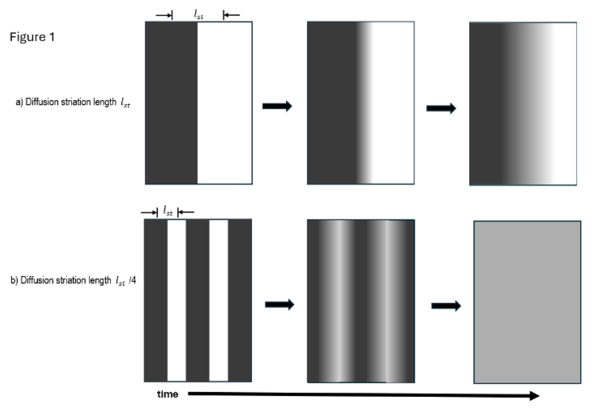
Figure 2.
PubMed search results for the last 20 years for total microfluidics references (■ ), DNA microfluidics references ( ♦ ) and RNA microfluidics references (● ).
Figure 2.
PubMed search results for the last 20 years for total microfluidics references (■ ), DNA microfluidics references ( ♦ ) and RNA microfluidics references (● ).
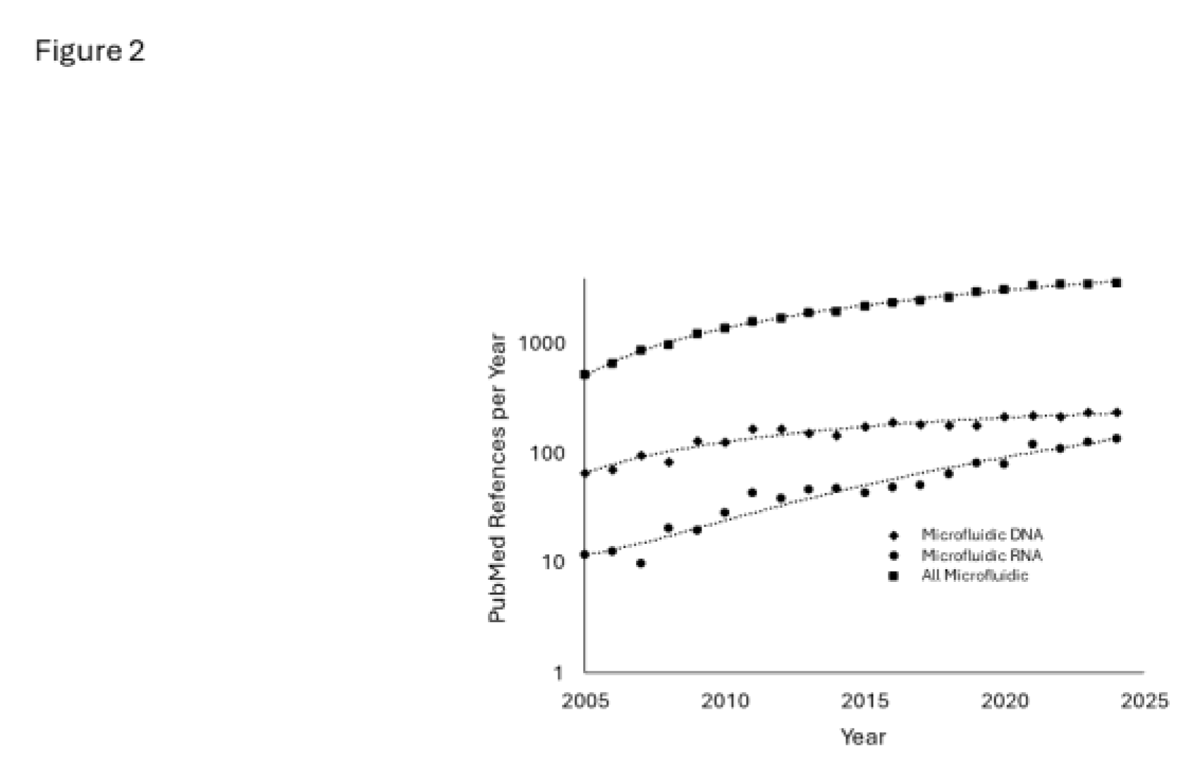
Figure 3.
Five simple drawings of common microfluidic mixer designs. The input ports for mixing fluids are designated as and , while the combined fluid output port is
designated a
Figure 3.
Five simple drawings of common microfluidic mixer designs. The input ports for mixing fluids are designated as and , while the combined fluid output port is
designated a
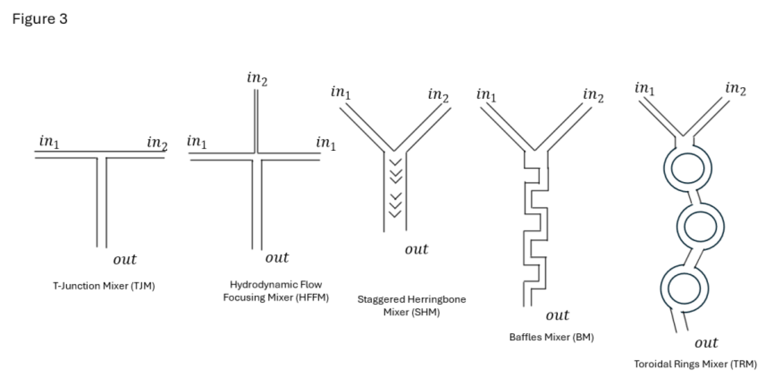
Figure 4.
Simple drawings of a Confined Impinging Jet (CIJ) turbulent flow mixer showing side view (a) and top view (b) turbulent mixer.
Figure 4.
Simple drawings of a Confined Impinging Jet (CIJ) turbulent flow mixer showing side view (a) and top view (b) turbulent mixer.
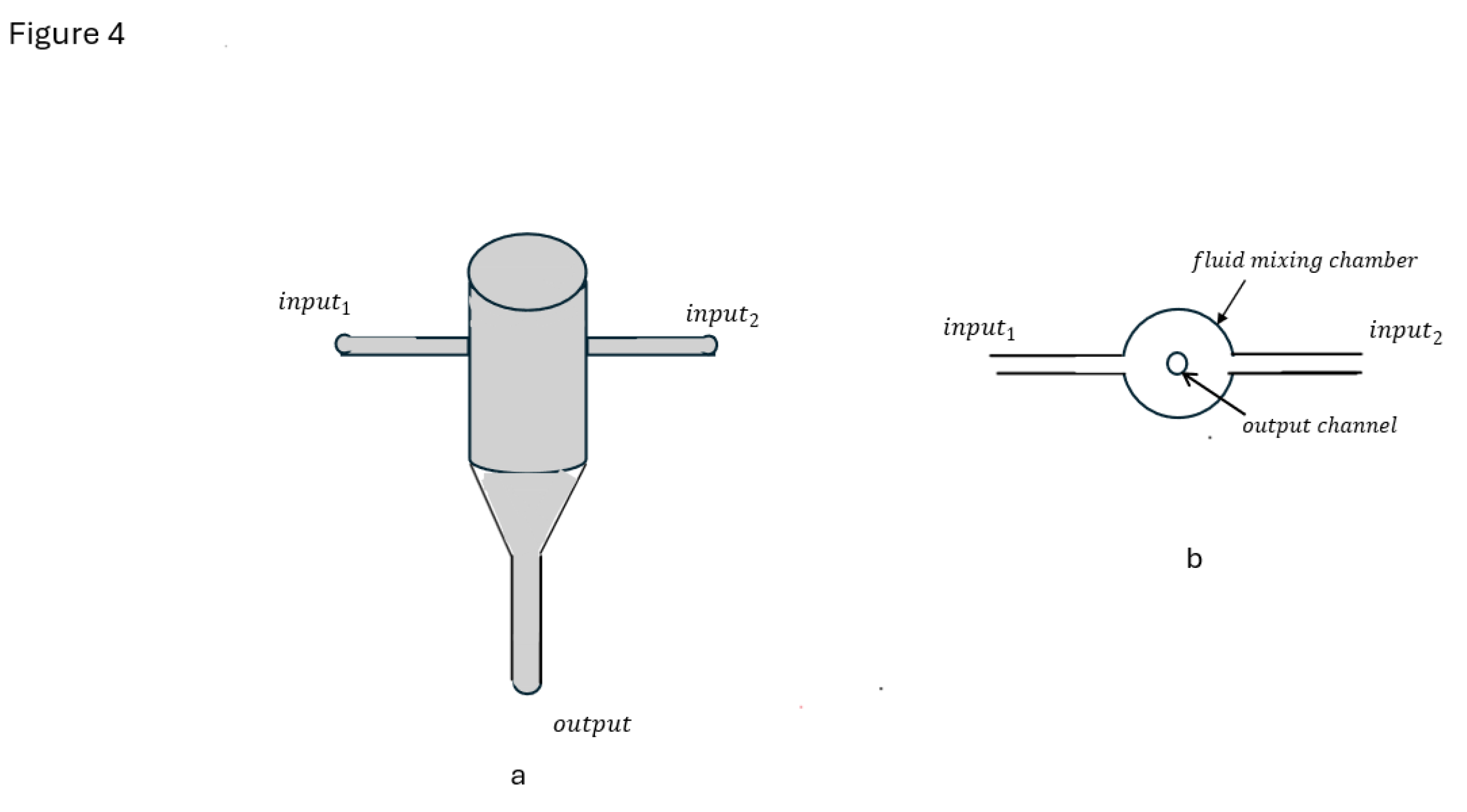
Figure 5.
Simple drawings of 4-jet Multi-Inlet Vortex Mixer (MIVM) showing side view (a) and top (b) of the turbulent mixer.
Figure 5.
Simple drawings of 4-jet Multi-Inlet Vortex Mixer (MIVM) showing side view (a) and top (b) of the turbulent mixer.
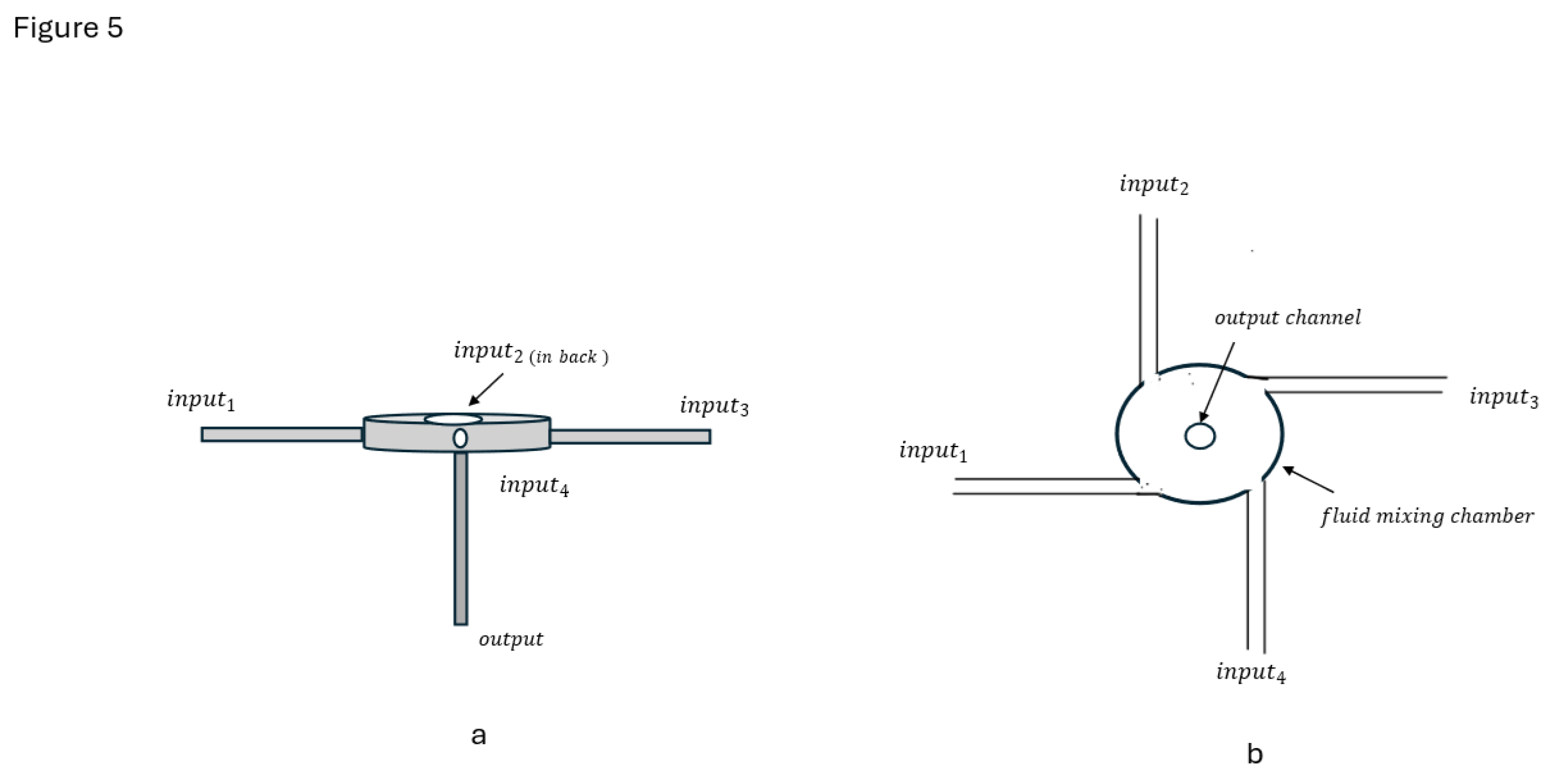
| Mixing Method | DLS Diameter, nm |
ζ-Potential, mV | mRNA EE %* | HeLa Cell In vitro Transfection, RLU /1000 cells |
HeLa Cell Viability |
|---|---|---|---|---|---|
| Manual Pipette | ≈ 140 | ≈ 0.5 | >95 % | ≈ 15 | ≈ 100 % |
| Two-Jet CIJ Mixer | ≈ 90 | ≈ 2.0 | >95 % | ≈ 100 | ≈ 100 % |
| Four-Jet MIVM | ≈ 90 | ≈ 1.0 | >95 % | ≈ 100 | ≈ 100 % |
From: Subraveti, S.N., et al., Synthesizing Lipid Nanoparticles by Turbulent Flow in Confined Impinging Jet Mixers. J Vis Exp, 2024(210), *Encapsulation Efficiency.
| Process Condition |
Fluorescently Identified Particle | Relative Population by Number | mRNA Copy per Particle | Average mRNA EE % | Average DLS Diameter, nm |
Average ζ -Potential, mV |
|---|---|---|---|---|---|---|
| Initial LNP, Post T-mixing 3:1, Aqueous: Ethanol (v/v) Mixed Solution pH 4.0 |
Lipophilic mRNA Complex (LNC) | 34 ± 8 % | 3.4 ± 0.4 | N/A | 106 ± 13 | + 45 ± 1 |
| Non-Lipophilic mRNA Complex (NLNC) | 25 ± 4 % | 1.3 ± 0.2 | ||||
| mRNA Lipid Nanoparticle (LNP) | 0% | N/A | ||||
| Empty Particle, i.e. No mRNA (ENP) | 41 ± 10 % | 0 | ||||
| Final Process LNP, Post-Dialysis Aqueous pH 7.4 Buffer |
Lipophilic mRNA Complex (LNC) | 0 | N/A | 94.2 ± 0.4 % | 120 ± 6 | - 6.3 ± 1.3 |
| Non-Lipophilic mRNA Complex (NLNC) |
0 | N/A | ||||
| mRNA Lipid Nanoparticle (LNP) | 23 ± 8 % | 2.8 ± 0.4 | ||||
| Empty Particle, i.e. No mRNA (ENP) | 77 ± 8 % | N/A |
From: Li, S., et al., Payload distribution and capacity of mRNA lipid nanoparticles. Nat Commun, 2022.
Disclaimer/Publisher’s Note: The statements, opinions and data contained in all publications are solely those of the individual author(s) and contributor(s) and not of MDPI and/or the editor(s). MDPI and/or the editor(s) disclaim responsibility for any injury to people or property resulting from any ideas, methods, instructions or products referred to in the content. |
© 2025 by the authors. Licensee MDPI, Basel, Switzerland. This article is an open access article distributed under the terms and conditions of the Creative Commons Attribution (CC BY) license (http://creativecommons.org/licenses/by/4.0/).
Copyright: This open access article is published under a Creative Commons CC BY 4.0 license, which permit the free download, distribution, and reuse, provided that the author and preprint are cited in any reuse.


