Submitted:
16 July 2025
Posted:
17 July 2025
You are already at the latest version
Abstract
With the advancement of building industrialization and the concept of sustainable development, modular and disassemblable buildings, as an efficient and environmentally friendly architectural form, have significant potential in scenarios such as emergency housing and rural construction. In response to issues such as insufficient component compatibility, low disassembly and assembly efficiency, and low integration, this paper proposes a solution based on the Design for Manufacturing and Assembly (DFMA) theory. Taking M-Box 1.0 as a case study, it explores design strategies from four aspects: product modularization, logistics optimization, rational disassembly and assembly, and component integration. Data shows that compared with the construction and assembly of the same-scale steel structure, the construction time of this building is shortened by 86%, the construction period is compressed by 36%, and the cost is reduced by 73.3%. The research reveals the advantages of DFMA-oriented design and has substantial significance for promoting the efficient and energy-saving development of building industrialization.
Keywords:
DFMA
; modular building
; demountable building
; building products
; design strategies
; M-Box1.0
1. Introduction
1.1. Research Background
As the“hardest hit”area in terms of energy consumption and carbon emissions, the construction industry is facing severe environmental pressures. Data show that the industry consumes nearly 40% of the world's available energy and produces one-third of the world's total greenhouse gas emissions[1,2]. Of these emissions, more than 50% are from carbon dioxide emissions associated with buildings and raw materials[3,4]. Statistics from the International Energy Agency (IEA) reveal that, due to their large number and total floor area, residential buildings account for a much larger share of global energy consumption than commercial buildings do [5]. Against this backdrop, reducing the building sector's energy demand and minimizing buildings' environmental impact while improving the design process has become a critical issue that needs to be addressed. In the face of such challenges, modular demountable buildings are necessary. Their efficient, flexible, and environmentally friendly characteristics can accurately respond to the diverse needs of emergency housing and rural construction and provide an important solution to alleviate the construction industry's environmental pressure [6].
The application of Design for Manufacturing and Assembly (DFMA) theory has given the construction industry a solid foundation for its transformation [7]. This design concept, which has a long history in the manufacturing field, can effectively solve the long-standing problems of low productivity, time delay, cost overruns and poor safety in the construction field [8]. Through the introduction of DFMA theory, the organic integration of design, manufacturing and assembly can be realized, which not only fits the development direction of improving quality and efficiency in the construction industry, but also provides theoretical guidance for the promotion of modular disassembled buildings, and pushes the construction industry to move forward in the direction of higher efficiency, environmental protection and sustainability.
1.2. Literature Review
1.2.1. Architectural Product Design for DFMA
DFMA requires that manufacturability and assembly be considered during the design phase of product development.The focus of the DFMA strategy is to improve ease of manufacturing and assembly by simplifying the product and its components. With DFMA design strategies, barriers in the manufacturing and assembly phases can be minimized or eliminated from product production [9].DfMA, initially used in World War II weapons production by companies such as Ford and Crest[10], has become the core of design for manufacturing, with an emphasis on considering manufacturing and assembly in the design phase to optimize the production process, reduce costs, and improve efficiency [11]. Many scholars try to apply the DFMA method of manufacturing to the field of construction, such as Cao [12] et al. build a DFMA design framework through a modular project of wood structure to show how to realize the collaborative optimization of design and manufacturing through ontology and rule system [13]; Dongchen Han et al. build a three-part implementation base containing DfM (Design for Manufacturing) and DfA (Design for Assembly) (Integrated Project Delivery IPD, Parametric design, BIM collaboration) [14]; Chen Gang et al. introduced the DFMA concept into the design of subway parking lot components, and improved manufacturability and assemblability through standardization and parametric modeling [15]; Cong Meng et al. took the case of portable aluminum alloy building as a case study, and put forward the design mode of “full-process research and development + integrated team + information platform”, which implies the DFMA idea. The DFMA idea is implied[16]. The above studies show that the application of DFMA in architectural product design has shifted from theoretical exploration to practical verification, but domestic and international practices are mostly focused on the transformation from design-led architectural solutions to the participation of DFMA in optimizing architectural solutions, and there is insufficient attention to the participation of DFMA strategy in the whole process of construction and manufacturing, and to the anticipation of and the elimination of the conflicts in the manufacturing and assembly phases in advance.
1.2.2. Modular Demountable Buildings
Modular demountable building is a deep integration of construction industrialization and the concept of sustainable development, which breaks down the building into reusable functional modules, and the core lies in the efficient use of the whole life cycle of the building through the standardized modules and demountable connection technology[17]. Demountable buildings can reduce the amount of construction waste generated through the recycling of materials, showing great potential for development, which has the characteristics of high flexibility, reusable, fast construction speed and environmental protection and energy saving. Many scholars have carried out related research: Yan Hongliang put forward the innovative concept of “N times removable mobile building is equivalent to permanent building”[18]; Hu Feipeng researched the construction technology of removable dry-hanging stone curtain wall, and developed a convenient method of removable stone curtain wall construction [19]. In the actual project, the design scheme of removable space steel structure of Vanke sales office in Guangzhou South Station[20]and so on, have accumulated experience in building composition, component connection, assembly process and so on.
However, currently demountable buildings are still facing high cost problems, for example, Galle's study showed that demountable building refurbishment methods cost 16% more than traditional methods, and the initial cost of the interior demountable wall type is 3% more, showing that the technology is not yet fully matured [21]; FN Rasmussen et al. compared the environmental impact of recycled-materials buildings with demolition oriented design (DFD) buildings, and the study found that there is currently no environmental advantage to DFD buildings [22]. Therefore, it is necessary to carry out systematic optimization throughout the whole life cycle of modular disassembled buildings, from manufacturing to assembly, which is highly compatible with the mature DFMA theory in the manufacturing field. In addition, there is still a theoretical gap in the existing literature on specific DFMA strategies for modular disassembled buildings. Therefore, DfMA strategies need to be constructed based on the characteristics of modular disassembled building products in terms of construction and manufacturing.
1.3. Research Purpose and Structure
This study aims to explore the design strategy of modular disassembled building products based on DFMA theory, and to verify it in practice through the typical case of M-Box1.0 . Specifically, the first is to construct a systematic DFMA design strategy framework, covering four key dimensions: modularization of product systems, rationalization of assembly methods, optimization of logistics and transportation, and integrated design of components; the second is to demonstrate how these strategies are transformed into actual architectural product design through the design practice of M-Box1.0; and the third is to analyze the effects of M-Box1.0 in terms of performance enhancement, shortened construction period, cost reduction, and sustainability enhancement, and to provide an opportunity for the development of a new design strategy for building products. Thirdly, quantitatively analyze the effect of M-Box1.0 in terms of performance improvement, construction period reduction, cost reduction, and sustainability enhancement, etc., to provide scientific basis and practical examples for the design optimization of modular dismantleable building products, and help the industrialization of construction develop in the direction of high efficiency, energy saving, and environmental protection.
This paper is divided into five main parts. The first part is the introduction, which explains the importance of modular demountable building in the context of construction industrialization, combs through the current status of the application of DFMA theory and research gaps, and introduces the research purpose of this paper. The second part introduces the research methodology, detailing the four design strategies proposed based on DFMA theory and their theoretical basis and application logic. The third part focuses on the design practice of M-Box1.0 based on DFMA, combining with practical cases to explain the specific implementation and innovation of each strategy in product design, with relevant charts to assist understanding. The fourth part verifies the implementation effect of M-Box1.0, quantitatively analyzing the four aspects of performance, duration, cost and sustainability, and highlighting its advantages compared with traditional buildings. The fifth part is the conclusion, which summarizes the research results, clarifies the performance enhancement achieved by M-Box1.0 through the DFMA strategy and its value to the development of the industry, and at the same time, points out the limitations of the research and the future research direction, which will provide a reference for the subsequent research .
2. Methods
Aiming at the shortcomings of the current application of DFMA theory in the field of modular disassembled buildings, this study combines the core idea of DFMA with the construction characteristics of building products, and puts forward four targeted design strategies, which aim to optimize the whole process of modular disassembled buildings from factory manufacturing, logistics and transportation to on-site assembly, so as to achieve a balance between manufacturability, assemblability, efficiency and sustainability (Figure 1).
2.1. Modular Design of the Product System
This strategy simplifies the complex structure of building products by systematically dividing them into modules. The building is disassembled into standardized and functionally clear modules to reduce component redundancy and clarify the logical connection between parts. The modular system adopts a hierarchical structure to adapt to the spatial combination of diverse scenarios (e.g. emergency housing, rural construction). This division not only facilitates the parallel production of multiple components in the factory, but also simplifies the on-site assembly process - workers can quickly assemble them according to a clear labeling and classification system; at the same time, the modular design supports users to customize the spatial configuration according to their needs, which strikes a balance between standardized production and personalized needs.
2.2. Rationalization of Assembly Methods
Given that there is no absolute positive correlation between high prefabrication rate and ease of assembly, the strategy emphasizes balancing manufacturability and assemblability through technical optimization. Specifically, it includes: designing embedded angle yards, riveting bolts and other connecting nodes to simplify on-site operation and reduce reliance on complex tools or highly skilled labor; simulating the assembly process with the help of virtual simulation tools, such as Navisworks, to check the conflict of multi-worker cross operation in advance and optimize the construction process; and utilizing parametric modeling software, such as Inventor, to accurately control the design error and ensure that the component dimensions are matched to reduce on-site adjustment and rework. parametric modeling software such as Inventor to accurately control design errors, ensure component size matching, and reduce on-site adjustments and rework.
2.3. Optimized Design of Logistics and Transportation
Unlike manufacturing products, building components involve off-site production and on-site assembly, making transportation a key bottleneck. The strategy improves transportation efficiency by optimizing the size and packaging of the components: adopting the “split-piece transportation” mode (instead of whole box transportation), disassembling the modules into flat and regular components to maximize the loading capacity of a single vehicle and reduce the number of transportation times; at the same time, the design of the components prioritizes the use of simple and regular forms to reduce the number of corners and sharp structures, thus reducing the risk of damage during transportation and further controlling the cost. At the same time, the design of the components prioritizes the use of simple and regular forms, reducing corners and sharp structures, reducing the risk of damage during transportation, and realizing “near-zero-damage” delivery to further control costs.
2.4. Integrated Design of Components
Based on material properties and construction logic, multiple functions are integrated into a single component to improve manufacturability and assemblability. For example, integrating decorative, structural, and waterproofing functions into a single component (e.g., the “exoskeleton” structure of M-Box 1.0) reduces the number of parts and on-site installation steps. This integration not only improves assembly efficiency, but also reduces the need for overhead work, minimizes safety hazards, and improves the efficiency of on-site equipment and tools, further streamlining the construction process.
3. DFMA-Oriented Design Practice of M-Box1.0
M-Box 1.0 is a modular disassembled building product based on the DFMA (Design for Manufacturing and Assembly) concept (Figure 2). In its name, “M” contains double meaning: it points to‘module’, interpreting the modularity concept upheld by architectural design; it is also associated with “magic”, highlighting the flexibility shown in the assembly process of the building. M“ has a double meaning: it points to ”module“to explain the modularity concept of building design; it is also associated with ”magic“to emphasize the flexibility and convenience of the building in the assembly process, i.e. the ‘magic’ property of the disassembly process; and ”1.0" identifies it as the first generation product.
Box 1.0 has a wide range of product adaptations that can be applied to flexible space needs in B&Bs, residences, commercial activities, and specialized environments. The existing completed sample is equipped with many features for its application in the residential sector, including a living room, two bedrooms, a bathroom and two outdoor terraces (Figure 3). With a building area of 59.5 m², the house occupies 45 m² and can be assembled in 2 days.
3.1. Modular Design of the Product System
The M-Box 1.0 uses standardized modules and detachable connection technology (Figure 4). This technology overcomes the limitations of monolithic modular building products regarding space, transportation, and construction sites. The internal space and external shape can be adjusted according to actual needs, transforming from a single fixed mode to diversified variable modes. The modular components of the M-Box1.0 can be disassembled for transportation, effectively reducing the required road conditions and enabling the product to traverse complex environments, such as narrow, height- and width-restricted roads. The modular design of the M-Box1.0 enables assembly operations on smaller sites with complicated terrain, greatly expanding the application scenarios and promotional scope of modular, disassembled building products.
Considering the dismountable nature of building products, even if the building scale is not large, the number of components after disassembly is still quite large. The complex connections between each component will inevitably lead to an increase in connection problems, which in turn affects the efficiency of manufacturing and assembly [23]. Therefore, designing a simple and clearly divided system is beneficial to improving the efficiency of both manufacturing in the factory prefabrication stage and on-site workers' assembly.Such a design enables multiple types of work to be manufactured simultaneously, shortening the project cycle; the clear system classification allows workers to assemble according to the labels during assembly; and users can select configurations by category when purchasing. In response to this, this product constructs a three-level classification architecture for modular design (Figure 5): the first-level classification includes structural modules, appearance modules, equipment modules, and space modules; the second-level classification is further refined. For example, structural modules cover main structures (roof panels, wall panels, floor panels, internal partition walls) and auxiliary structures (foundations); appearance modules are subdivided into balcony, step, window, and handrail modules; equipment modules integrate air conditioning, photovoltaic, and wind turbine modules to meet the energy supply of the building; space modules include living room, bedrooms of different area specifications (9㎡, 13.5㎡), dining kitchen, bathroom, and staircase modules; the third-level classification focuses on specific components, including both basic components such as roof panels in the main structure and space components of different area specifications in the bedroom module, forming a hierarchical system architecture of "module - component - part".
In the design architecture of M-Box1.0, each type of module has specific functions, and different configurations of modules of the same type can be interchanged. The selection of module sizes takes into account the ergonomic user experience and the specifications of road transportation. With 1.5m and 3m as the basic modules, a standardized splicing system has been established. At present, architectural design has transformed from the "architectural work design mode" to the "architectural product design mode" [24]. The design concept of M-Box1.0 is rooted in the philosophy of product design. Designers are responsible for constructing the logical framework of module combination, while owners can flexibly select and combine modules within this framework according to their specific functional needs to create personalized spatial effects, thus highlighting the close and effective collaborative relationship between design and manufacturing.
3.2. Rationalized Design of Assembly Methods
3.2.1. Product Design Considering Assembly and Installation
The design of M-Box1.0 product, which connects two regular enclosure panels through embedded corner codes and blind rivet bolts (Figure 6), fully considers the convenience of assembly and installation. During installation, the top plate is pressed over the side plates, and the side plates rest on the bottom plate. The connection between them is achieved through the insertion of standardized L-shaped connectors, with the insertion position at the end of the main vertical ribs. They are fastened by high-strength bolts, and the position for embedding the waterproof rubber strip on the bent surface has been reserved through design. When the ends of the module openings are used to connect two modules, high-strength bolts are directly used to fasten the curled parts formed by the bending process. When modules are connected left and right, the side wall panel of one module is opened, and they are connected to each other with high-strength bolts. When modules are connected up and down, the top plate of the lower module is used as the bottom plate of the upper module. An opening is made at the upper part of the side wall rib, and a T-shaped connector is inserted and fastened with high-strength bolts. Through the combined application of these different connection methods, modules can be spliced into architectural forms with various shapes.Lifting rings are installed at the four corners of the top plate of each module, which match the hooks of the crane. The weight of each module panel is lower than the lifting capacity of small cranes, enabling quick and accurate transfer and lifting from the flatbed truck to the site (Figure 7).
3.2.2. Precise Control of Design Errors
Precise error control ensures product quality and construction efficiency. Relying on BIM technology, the team introduces Inventor software commonly used in the manufacturing industry in the product development stage, and builds models step by step to integrate the design of the building structure, enclosure system, and all kinds of pipelines for water supply and drainage, plumbing, heating, electricity, air conditioning, etc., with the assembled interior furnishings, panels, doors, and windows. The basic modeling is completed by accurately setting the size, shape, material and other parameters of each part, and the virtual assembly of components is carried out by using the software's component assembly function, and the specific size and design of components are adjusted in real time according to the matching accuracy between components (Figure 8). Once found, such as connection gaps and other problems, you can instantly adjust the design parameters in the software, optimize the connection, the design defects eliminated in the virtual stage, and ultimately generate a full set of construction drawings. The manufacturing party directly manufactures the components according to the drawings, and the construction and assembly party directly guides the construction according to the drawings, which ensures that the links are closely connected and the design errors are effectively and accurately controlled.
3.3. Logistics and Transportation Optimization
3.3.1. Design for Transportation of Dismantled Pieces
M-Box1.0 has fully considered the efficiency of logistics and transportation at the design stage. Most modular building products are transported as a whole in boxes, which are often difficult to pass when facing narrow mountain roads and complicated road conditions. M-Box1.0 disassembles the building into panels for transportation (Figure 9), which improves the assembly efficiency and the recyclability of the components. Compared with the “one-truck-one-box” box-type transportation of building products, the carrying capacity of a single truck is increased by 9 times, and the transportation cost is reduced by 60%. All the components of the 59.5m2 model house can be transported in a single trip by a single truck. For the convenience of transportation and the “near zero damage” of the product transportation, we designed the main components of the product with simple and regular shapes. The design takes into account the logic of the module division to ensure that each major component is regular in shape, minimizing corners and sharp points that may be easily damaged during transportation.
3.3.2. Integrated Design of Plumbing, Electrical and HVAC
Faced with the demountable nature of the building, the design process was adapted to the water supply and drainage, electrical and HVAC systems. This not only realizes the factory prefabrication of major equipment and pipelines, but also effectively improves the construction efficiency of building products. In the bathroom and other pipeline-intensive areas, the use of box-type integral transportation to achieve a complete factory prefabrication; other spaces of water, electricity, HVAC pipelines are integrated into the enclosure, the ends of the reserved interfaces and junction boxes, on-site enclosure splicing can be a plug-and-play connection. During the design work, the utility visualization software DFC was used to optimize the path layout of the utility lines, which significantly reduced the total length of the lines and minimized the number of times the utility lines traversed multiple boxed rooms (Figure 10). For the air-conditioning system, the design uses independent modules and selects an integrated air-conditioning unit to realize the integration of inlet and outlet air, avoiding interference with the design of other specialized systems.
3.4. Integrated Design of Components
Traditional building walls are generally constructed using a layered construction system, which requires the installation of independent structures such as finish layer, structural layer, waterproof layer, thermal insulation layer, isolation layer, and interior layer, etc. The material connection and process coordination between layers not only increase the construction complexity, but also easily lead to leakage, thermal bridges, etc. due to improper interface treatment.M-Box1.0 introduces mature sheet metal technology in the automobile manufacturing field into the construction process (Figure 11). M-Box1.0 has developed an exoskeleton structure system, which realizes a high degree of integration of component functions through the in-depth integration of material characteristics and construction logic.
The “exoskeleton”of M-Box 1.0 is a thin-walled lightweight steel structure consisting of a set of steel plates with bent edges, a ring-shaped frame and reinforcement bars. The geometric characteristics of the exoskeleton derive from the modular cylinder design: the rectangular frames of the top, side and bottom surfaces are connected by a ring to form a closed cylinder, and the “rebar” design (offsetting the columns and load-bearing beams at the edges of the traditional modules inwards) allows only a narrow bending surface to remain at the interface of the modules. The geometric features are derived from the modular silo design: the rectangular frame on the top, side and bottom surfaces is connected by a wrap-around connection to form a closed silo, and by means of the “rebar” design (the columns and load-bearing beams at the edges of the traditional modules are offset inwards), so that only a narrow curved surface is retained at the modular interface. This design avoids the material redundancy of “double beams and double columns” in conventional module connections, and creates a natural space for screw gun operation and waterproof tape grooves.
As a key component for structural strengthening, the circle frame was formed by bending Q345 steel (GB standard, modulus of elasticity 2.06×10⁸ kN/m², Poisson's ratio 0.3, weight capacity 76.98 kN/m³) in one piece, and the cross-section was designed as a box of 100mm×50mm×1.2mm (H×W×H), and its stress performance was verified by three-dimensional modeling using the Midas Gen software. Midas Gen software establishes a three-dimensional model to verify its stress performance: under the combined working condition of 1.3 times permanent load (including roof PV array weight 0.25 kN/m², equipment point load 1.5 kN) and 1.5 times live load (including snow load 0.55 kN/m², roof live load 2.0 kN/m²), the stress distribution of the frame is - 0.038~0.046 N/m², and the stress distribution is - 0.038~0.046 N/m², and the stress distribution is - 0.038~0.046 N/m². 0.046 N/m², and the maximum deformation is only 0.053mm, which is much lower than the limit value of 1/250 of the beam span (12mm) in GB50009-2012 specification, which verifies the mechanical efficiency of the integrated bending and molding structure (Figure 12).
The force analysis shows (Figure 13) that the “exoskeleton” wall formed by bending the 1.5 mm thick steel plate through sheet metal exhibits better force-resisting performance than the traditional steel pipe under the same material dosage. According to the “China Building Structure Design Load Code” (GB50009-2012) [25], the standard value of the residential category in the floor distributed live load of civil buildings is not less than 2.0kN/㎡. So in the building “exoskeleton” resistance to longitudinal pressure strength calculation, in addition to gravity load is also considered 2.0kN / m² of permanent load. After Inventor software finite element analysis shows that 1.5mm galvanized steel folded into the “exoskeleton” of the longitudinal deformation of the maximum amount of about 0.657mm (a), to meet the “technical standards for the detection of building structures” (GB/T 50344 - 2019) [26], the floor slab static load test qualified! The standard is “maximum deflection ≤ L/250 (L is the floor span)”. In the building “exoskeleton” anti-horizontal pressure strength checking, comprehensive consideration of wind load, earthquake load and other horizontal loads, as well as self-weight and other vertical loads, and according to the “China Building Structural Design Load Specification” (GB50009-2012) relevant provisions, to determine that the transverse pressure of 0.025Mpa, the “exoskeleton” of the building. The maximum transverse deformation of the “exoskeleton” is about 10.78mm(b), which meets the specification requirement that the maximum deflection (a kind of expression of deformation) is not more than 1/150 to 1/200 of the span of the general pressurized steel plate facade under the action of transverse pressure such as wind load.
4. Discussion
4.1. Performance Analysis
The geometry of the barrel-type structure has windows and doors that open primarily at the ends. First, the non-load-bearing structure at the ends of the cylindrical structure allows for the opening of a large area of windows and doors, permitting sufficient natural light to enter, ensuring that the interior space is adequately illuminated, while preventing glare. In addition, the form of open windows and doors at the ends can utilize the more narrow and long interior spaces to create temperature differences, which facilitates natural ventilation throughout the building and enhances convective airflow (0.8-6m/s) (Figure 14). Through the ventilation and natural light analysis of M-Box1.0, the building product meets the standards in key performance indicators.The regular space shape of M-Box1.0 further enhances the wind pressure ventilation effect, which is confirmed by the results of the building wind simulation (a) shown in Fig. The building interior is able to form good natural ventilation paths when the doors and windows are open. Sufficient natural light enters to ensure that the interior spaces are well lit while preventing glare. The natural lighting simulation shows (b) that more than 90% of the spaces are illuminated at an average daily illuminance level of more than 300 lux.The lighting coefficients of M-Box 1.0 all meet the requirements of the Building Lighting Design Standard (GB50033-2019).
4.2. Construction Period Analysis
On-site construction often requires constant coordination between the general contractor and various subcontractors. For example, the interior subcontractor had to wait until the structure was built, the home improvement subcontractor had to wait until the house was built to start measuring and fabricating, and the bathroom subcontractor had to wait until the structure was built to work on the bathrooms, and all of this waiting for each other's time was counted in the schedule, which means that all of this time was wasted. For M-Box 1.0, a project of several tens of square meters, these waiting or idle times are counted in days. During the on-site construction of M-Box 1.0 for DFMA, the team “put together” the entire building in 2 days with only 2 workers. An analysis of the building duration including fabrication, packing, transportation, assembly/build, idle, and waiting was performed (Table 1), and the general contractor was consulted to estimate the duration required to build a steel building of the same size. Compared to the construction period for a similarly sized steel building, the DFMA-oriented modular disassembled building product reduced the construction/assembly period by 86% and the total period by 36%.
4.3. Cost Analysis
The cost of construction products is divided into two main components: materials and labor. Labor costs for manufacturing workers are between 35% and 65% of the cost of workers working on site. Given the wage differential between on-site assembly and manufacturing, M-Box 1.0 saves on labor costs by shifting much of the manufacturing and assembly of building components to the factory. At the same time, further savings in on-site assembly/build costs can be realized by increasing the efficiency of the assembly process at the factory and reducing the idle and wait times that are prevalent in on-site construction. The material costs for both on-site and prefabricated construction are roughly equal; however, M-Box 1.0's “exoskeleton” structure is designed to reduce the amount of steel used while maintaining the same structural strength, so its material costs are relatively low. However, assembly construction for DFMA will inevitably incur additional costs, such as design and packaging costs, which will ultimately be apportioned to the total construction cost. While there are advantages and disadvantages to each, the results of the analysis show that the cost of M-Box 1.0 is 73.3% of the cost of a lightweight steel building of the same size(Table 2).
4.4. Sustainability
M-Box 1.0 modular dismantleable building product for DFMA was designed from the outset with recycling and reconstruction of building materials in mind(Table 3). The foundation and main structure are made of low-environmental impact (LEI) steel, which not only reduces carbon emissions by about 40% compared with traditional concrete, but also has a recycling rate of more than 95%; the internal components follow the standard of architectural modulus coordination, realizing the dual recycling mode of overall recycling of the modules and the dismantling of components for reuse, which effectively reduces the consumption of resources in the whole life cycle of the building. The structural design adopts the externally derived bionic skeleton structure to achieve the integrated and integrated design of decorative-structural-waterproof functions, reducing material redundancy and construction complexity, and lowering the articulation loss of traditional sub-projects by 25%.The cross-scenario interchangeable mechanism of standardized modular units in M-Box1.0 supports functional iteration and adaptive updating of the building within the use cycle, avoiding wasteful dismantling and reconstruction due to functional changes, reducing repeated decoration and unnecessary construction, and reducing the need for repeated renovations and unnecessary construction. M-Box1.0 minimizes the carbon emission of the building by establishing carbon reduction strategies at all stages of the life cycle, including material selection, operation management, structural innovation, and functional iteration.
5. Conclusions
In this study, M-Box1.0 is used as a case study to investigate the product design strategy of modular disassembled building oriented to DFMA. Through the implementation of the four core strategies based on DFMA, namely the modular design of the product system, the rationalization of the assembly method, the optimization of logistics and transportation, and the integrated design of the components, M-Box1.0 achieves a significant improvement in its performance. In terms of construction efficiency, compared with a traditional steel structure building of the same size, the construction/assembly time is reduced by 86%, the total construction period is compressed by 36%, and on-site assembly can be completed in 2 days with only 2 workers. In terms of economy, the overall cost is reduced by 73.3%, thanks to the reduction of material consumption (36.5% steel savings through the “exoskeleton” structure) and labor costs (transferring the manufacturing process to the factory). Environmentally friendly, the use of low-environmental impact (LEI) steel with a recycling rate of over 95%, a modular recycling system, and an integrated structure reduces lifecycle carbon emissions by about 40% compared to a traditional concrete structure, while minimizing construction waste through prefabrication and demountable connections.
The innovation points of this research are reflected in three aspects: First, it realizes the deep integration of DFMA theory and modular disassemblable buildings, converting the design for manufacturing concept into operational strategies such as sheet transportation and embedded corner code connection, breaking the barrier between architectural design and industrial production. Second, it proposes a three-level modular classification system (module - component - part) and an "exoskeleton" structure (integrating decoration, structure, and waterproofing functions), resolving the contradiction among manufacturing efficiency, assembly convenience, and structural stability in modular buildings. Third, it visualizes and optimizes the entire process from design to construction and logistics through digital tools such as BIM, Inventor, and DFC, avoiding conflicts in the manufacturing and assembly stages in advance, and providing a new technical paradigm for the industrialization of construction.
However, there are still limitations: there is insufficient data on the long-term performance of M-Box 1.0, such as structural stability under repeated disassembly and aging of materials after decades of use; current applications are mainly limited to small houses and lodgings, and its applicability in high-rise or complex functional buildings has not yet been verified; and the practicability of the recycling system (e.g., maintenance of component integrity during disassembly) needs to be further verified.
Future research should focus on:
- Expanding application scenarios to high-rise buildings, public buildings, and buildings in extreme environments, and testing the adaptability of DFMA strategies in complex structures;;
- Establish a long-term performance monitoring system to track the structural performance, thermal insulation and waterproof durability throughout the life cycle;
- Optimize recycling technology, develop intelligent disassembly equipment and component health assessment tools, and improve material reuse efficiency;
- Deepen digital integration, explore the combination of DFMA, parametric design, and machine learning, and realize the automatic optimization of modular systems.
Author Contributions
Conceptualization, M.W. ,Y.J. and J.W.; methodology, J.W.,P.M.; software, M.W.,Y.Y.; validation, M.W. ,F.L.,Y.J.,P.M. and J.W.; formal analysis, M.W. ,F.L. and Y.Y.; investigation, Y.Y.; resources, Y.J.,P.M.; data curation, M.W.; writing—original draft preparation, M.W. and J.W.; writing—review and editing, M.W. and Y.J.; visualization, M.W.; supervision, J.W.; project administration, J.W.; funding acquisition, J.W. All authors have read and agreed to the published version of the manuscript. Authorship must be limited to those who have contributed substantially to the work reported.
Funding
This research was funded by "Smart Building" New Engineering Construction Project, grant number PYGJ-B042.
Data Availability Statement
The data supporting the findings of this study are available within the article and its supplementary materials. The datasets generated and/or analyzed during the current study, including structural stress simulation results, construction period statistics, cost breakdowns, and carbon emission data, are available from the corresponding author upon reasonable request. For further details, please refer to the MDPI Research Data Policies (https://www.mdpi.com/ethics).
Acknowledgments
The authors would like to thank the technical team involved in the manufacturing and on-site assembly of the M-Box1.0 prototype for their practical support. During the preparation of this manuscript, the authors used DeepL Translator (Version 2023.10) for the translation of Chinese literature abstracts and technical terms. The authors have reviewed and edited the output and take full responsibility for the content of this publication.
Conflicts of Interest
The authors declare no conflicts of interest. The funders had no role in the design of the study; in the collection, analyses, or interpretation of data; in the writing of the manuscript; or in the decision to publish the results.
Abbreviations
The following abbreviations are used in this manuscript:
| MDPI | Multidisciplinary Digital Publishing Institute |
| DFMA | Design for Manufacturing and Assembly |
| IEA | International Energy Agency |
References
- Chen, Y.S.; Wu, J.W. Component circulation: Dismantlable building design from product to thinking. Archit. J. 2024, 172–177. [Google Scholar]
- Li, Y.Q.; Du, Z.J.; Lu, Z.H.; et al. Research and practice of integrated construction technology for prefabricated steel structure buildings. Prog. Steel Build. Struct. 2021, 23, 12–25. [Google Scholar] [CrossRef]
- Han, D.C.; Zhang, H.; Liu, Y.; et al. From BIM to BDT: Research on the conception of Building Digital Twin (BDT). Archit. J. 2020, 95–100. [Google Scholar]
- Gao, S.; Jin, R.Y.; Lu, W.S. Design for manufacture and assembly in construction: a review. Build. Res. Inf. 2019, 48, 538–550. [Google Scholar] [CrossRef]
- Boothroyd, G. Product Design for Manufacture and Assembly. Comput.-Aided Des. 1994, 505–520. [Google Scholar] [CrossRef]
- Cao, J.; Vakaj, E.; Soman, R.K.; Hall, D.M. Ontology-based manufacturability analysis automation for industrialized construction. Autom. Constr. 2022, 139, 104277. [Google Scholar] [CrossRef]
- Han, D.C.; Yin, H.X.; Qu, M.; et al. Research on design strategies for manufacturing and assembly oriented to customized prefabricated buildings — A case study of Lotus Residence. J. West. Resid. Environ. 2022, 37, 30–35. [Google Scholar]
- Chen, G.; Dong, D.D.; Jiang, Y.B.; et al. BIM parametric design of components for a metro parking lot oriented to DFMA. Exp. Technol. Manag. 2024, 41, 135–142. [Google Scholar]
- Cong, M.; Zhang, H. Transformation of design and construction — Research and development of movable aluminum alloy building products. Archit. Cult. 2024, 143–144. [Google Scholar]
- China's construction waste output is increasingly serious but with low resource utilization rate[N/OL]. Legal Daily, 2023-01-10. [Online]. Available online: http://www.ce.cn/cysc/stwm/gd/202009/24/t20200924_35806871.shtml (accessed on day month year).
- Yan, H.L.; Luo, D. Discussion on dismantlable buildings. Hous. Sci. 2015, 35, 24–28. [Google Scholar] [CrossRef]
- Hu, F.P. Application analysis of construction technology for dismantlable dry-hanging stone curtain walls. Res. Hous. 2022, 29–31. [Google Scholar]
- Zhang, Q.; Ma, M.; Zhao, P.F. Design research on dismantlable spatial steel structure of Vanke sales office at Guangzhou South Railway Station[C]//China Academy of Building Research, Spatial Structure Committee of Bridge and Structural Engineering Branch of China Civil Engineering Society. Proceedings of the 16th National Spatial Structures Academic Conference. Beijing: China Academy of Building Research, 2016: 627-634.
- Galle, W.; De Temmerman, N.; De Meyer, R. Integrating scenarios into life cycle assessment: Understanding the value and financial feasibility of a demountable building. Buildings 2017, 7, 64. [Google Scholar] [CrossRef]
- Rasmussen, F.N.; Birkved, M.; Birgisdóttir, H. Upcycling and Design for Disassembly–LCA of buildings employing circular design strategies[C]//IOP Conference Series: Earth and Environmental Science. IOP Publishing 2019, 225, 012040. [Google Scholar] [CrossRef]
- Da Rocha, C.G.; Sattler, M.A. A discussion on the reuse of building components in Brazil: An analysis of major social, economical and legal factors. Resour. Conserv. Recycl. 2009, 54, 104–112. [Google Scholar] [CrossRef]
- Cong, M.; Zhang, H.; Liu, W.H.; et al. Research on productized design method and construction management technology for industrialized rural buildings. Ind. Constr. 2024, 54, 97–109. [Google Scholar] [CrossRef]
- Huang, B.J.; Gao, X.Y.; Xu, X.Z.; et al. A Life Cycle Thinking Framework to Mitigate the Environmental Impact of Building Materials. One Earth 2020, 3, 564–573. [Google Scholar] [CrossRef]
- Abdel-Malek, K.; Maropis, N. A design-to-manufacture case study: Automatic design of post-fabrication mechanisms for tubular components. J. Manuf. Syst. 1998, 17, 183–195. [Google Scholar] [CrossRef]
- Deng, E.F.; Zong, L.; Ding, Y.; et al. Seismic performance of mid-to-high rise modular steel construction - A critical review[J/OL]. Thin-Walled Structures 2020, 155, 106924. [Google Scholar] [CrossRef]
- Gatheeshgar, P.; Poologanathan, K.; Gunalan, S.; et al. Optimised cold-formed steel beams in modular building applications[J/OL]. Journal of Building Engineering 2020, 32, 101607. [Google Scholar] [CrossRef]
- Gatheeshgar P, Poologanathan K, Gunalan S; et al. Development of affordable steel-framed modular buildings for emergency situations (Covid-19)[J/OL]. Structures 2021, 31, 862–875. [CrossRef]
- Chai T J, Tan C S, Chow T K; et al. A Review on Prefab Industrialised Building System Modular Construction in Malaysia: The Perspective of Non-structural Studies[C/OL]//Awang M, Isa M H. The Advances in Civil Engineering Materials. Springer: Singapore, 2019; pp. 11–21.
- Navaratnam, S.; Ngo, T.; Gunawardena, T.; et al. Performance Review of Prefabricated Building Systems and Future Research in Australia[J/OL]. Buildings 2019, 9, 38. [Google Scholar] [CrossRef]
- GB 50009-2012; Code for Loads on Building Structures[S]. China Architecture & Building Press: Beijing, 2012.
- GB/T 50344-2019, Standard for Inspection Technology of Building Structures[S]. China Architecture & Building Press: Beijing, 2019.
Figure 1.
Methodology Workflow.
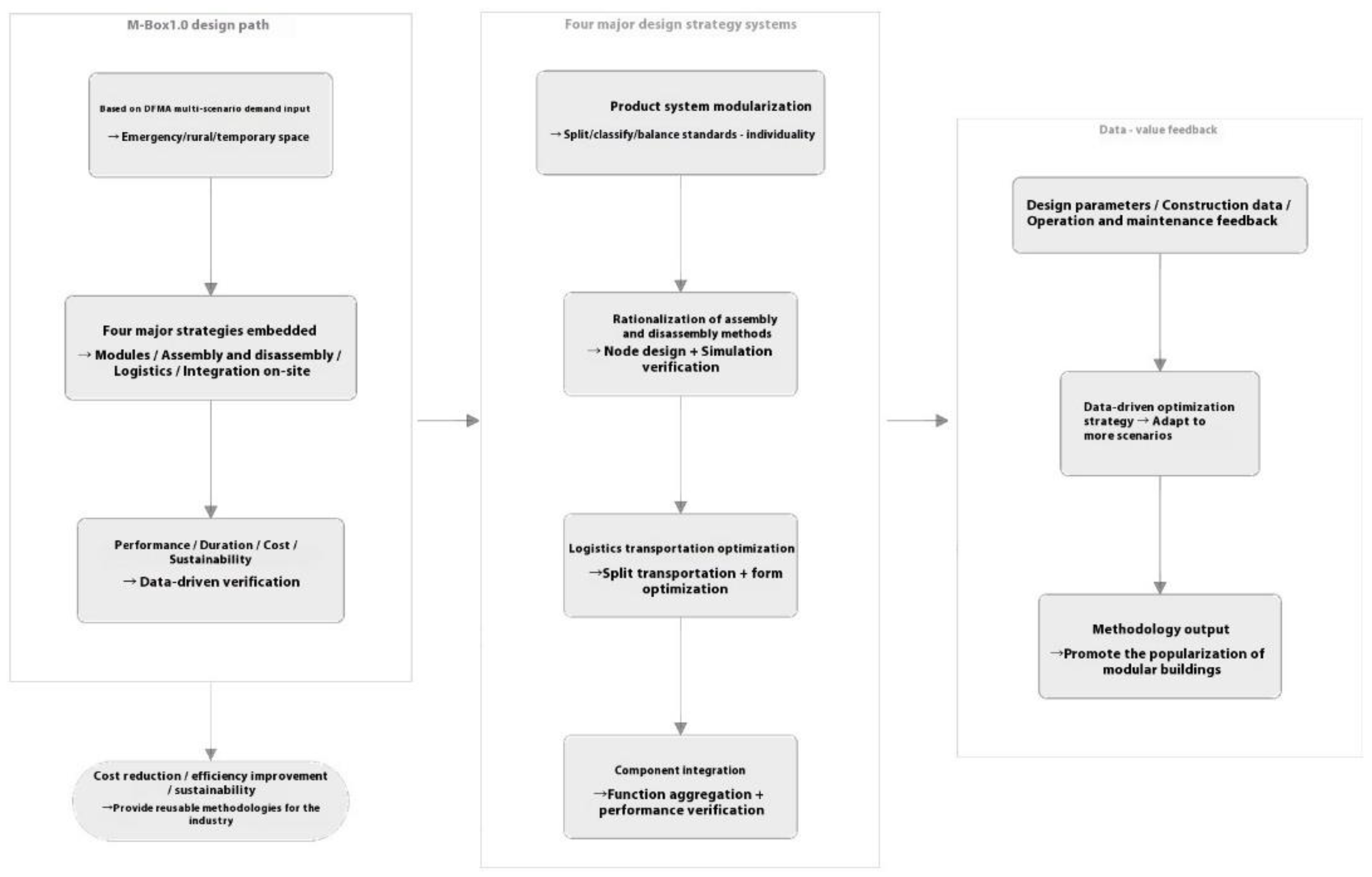
Figure 2.
Figure 2. M-Box1.0 Completed Real - scene.
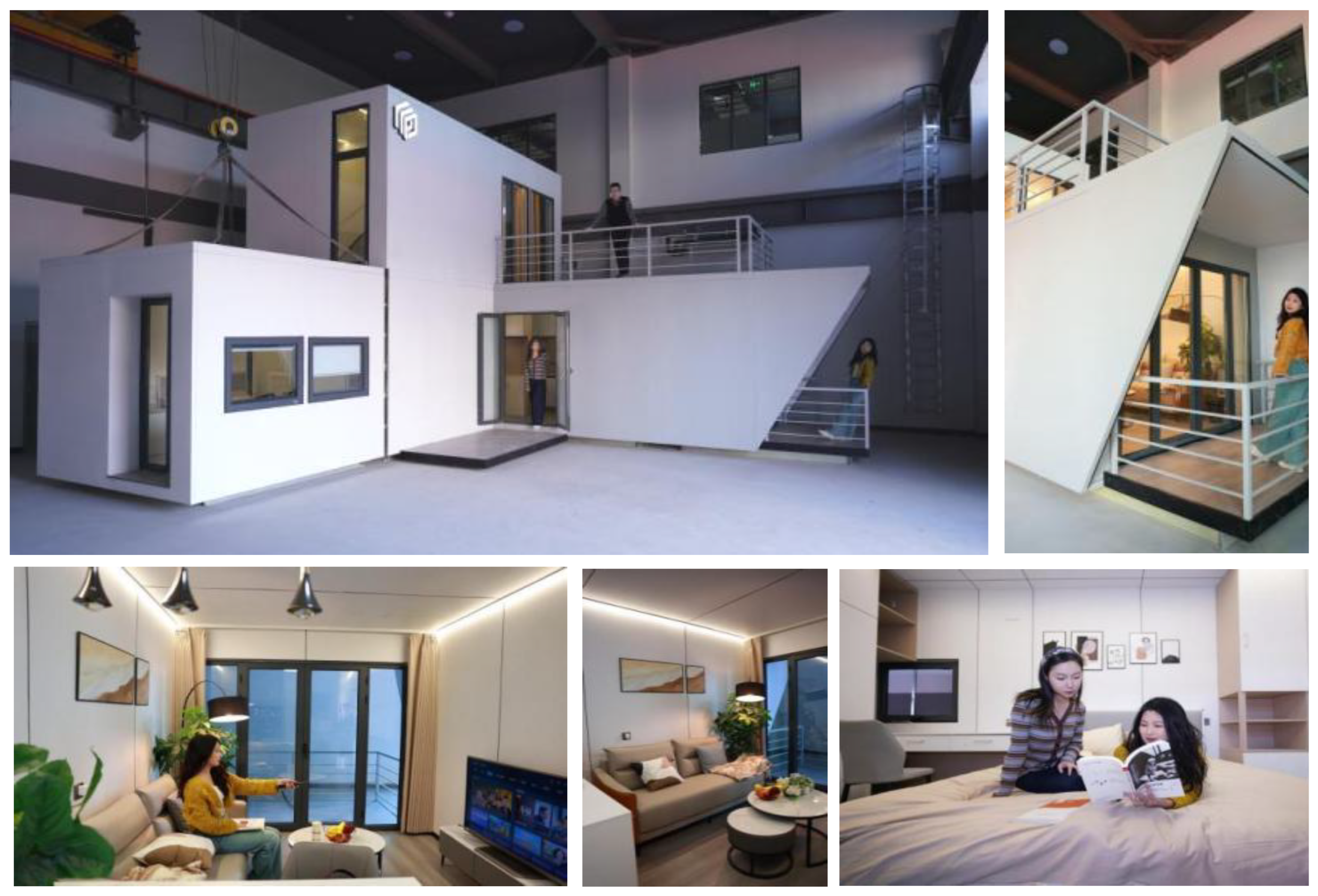
Figure 3.
Floor Plan of M-Box1.0. (a) Ground Floor Plan of M-Box1.0; (b) Second Floor Plan of M-Box1.0.
Figure 3.
Floor Plan of M-Box1.0. (a) Ground Floor Plan of M-Box1.0; (b) Second Floor Plan of M-Box1.0.
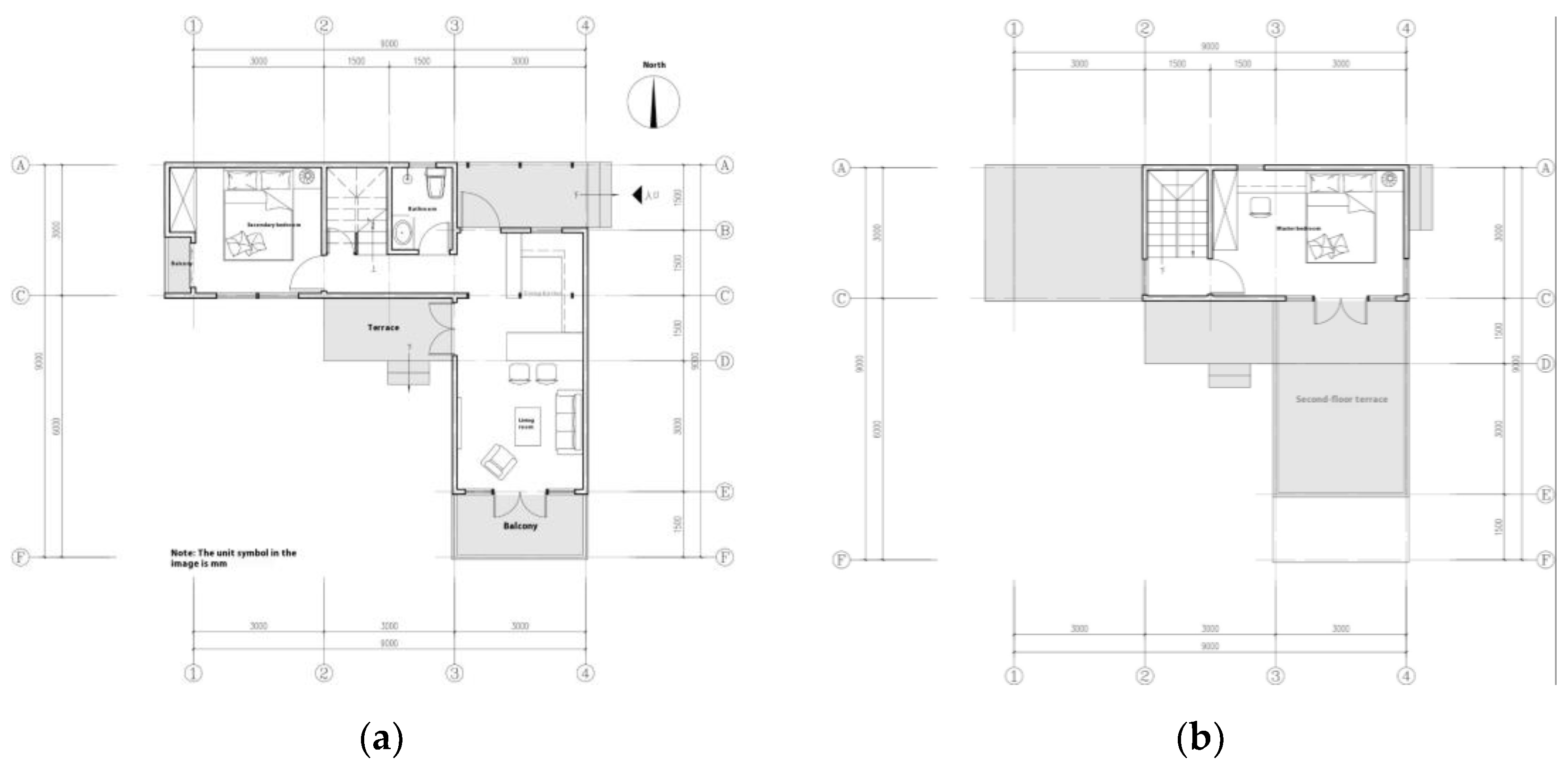
Figure 4.
Figure 4. M-Box 1.0 Detachable System.
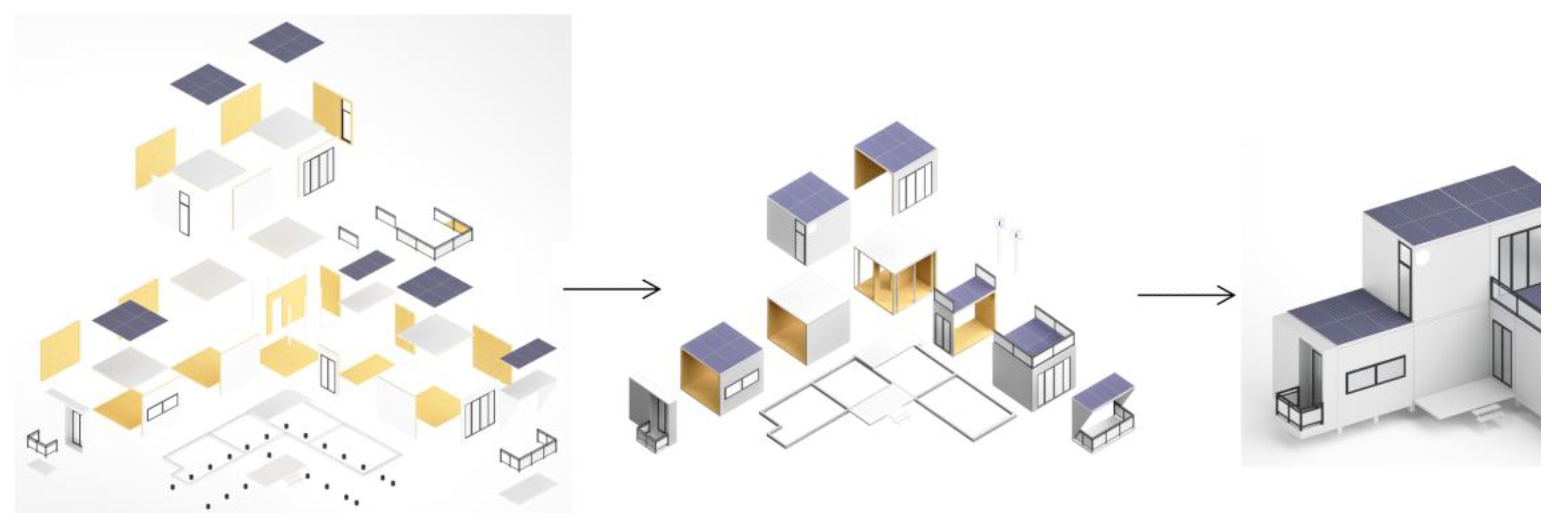
Figure 5.
Figure 5. Three-level Classification Architecture of M-Box1.0 Modular Design.
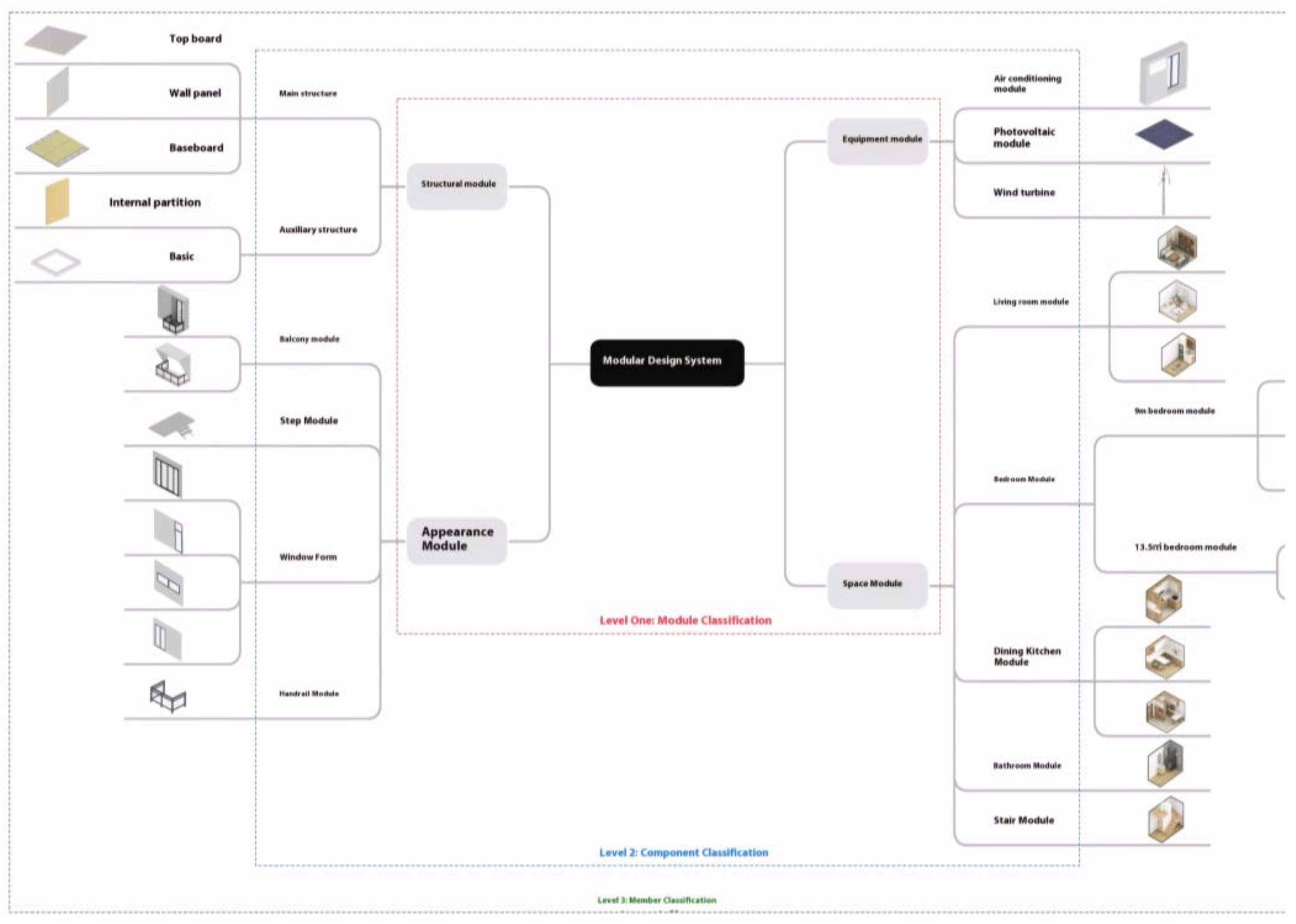
Figure 6.
Figure 6. Module connection mode;(a)standard module;(b)up and down;(c) front and rear; (d) Angle contact.
Figure 6.
Figure 6. Module connection mode;(a)standard module;(b)up and down;(c) front and rear; (d) Angle contact.

Figure 7.
Figure 7. Module lifting diagram.
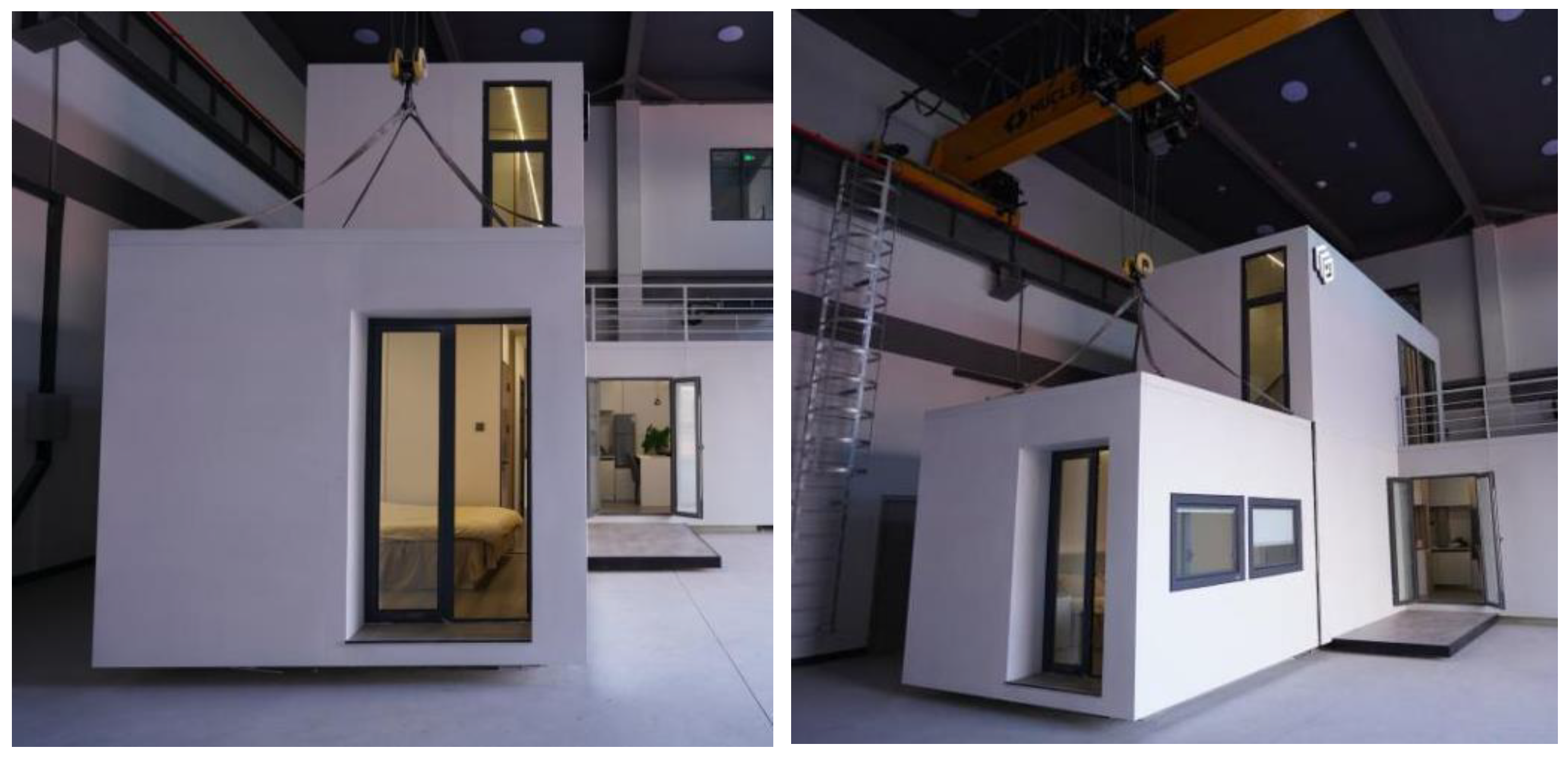
Figure 8.
Figure 8. Inventor Interface. (a) Inventor Part Parameter Interface; (b) Inventor Assembly Parameters Interface.
Figure 8.
Figure 8. Inventor Interface. (a) Inventor Part Parameter Interface; (b) Inventor Assembly Parameters Interface.
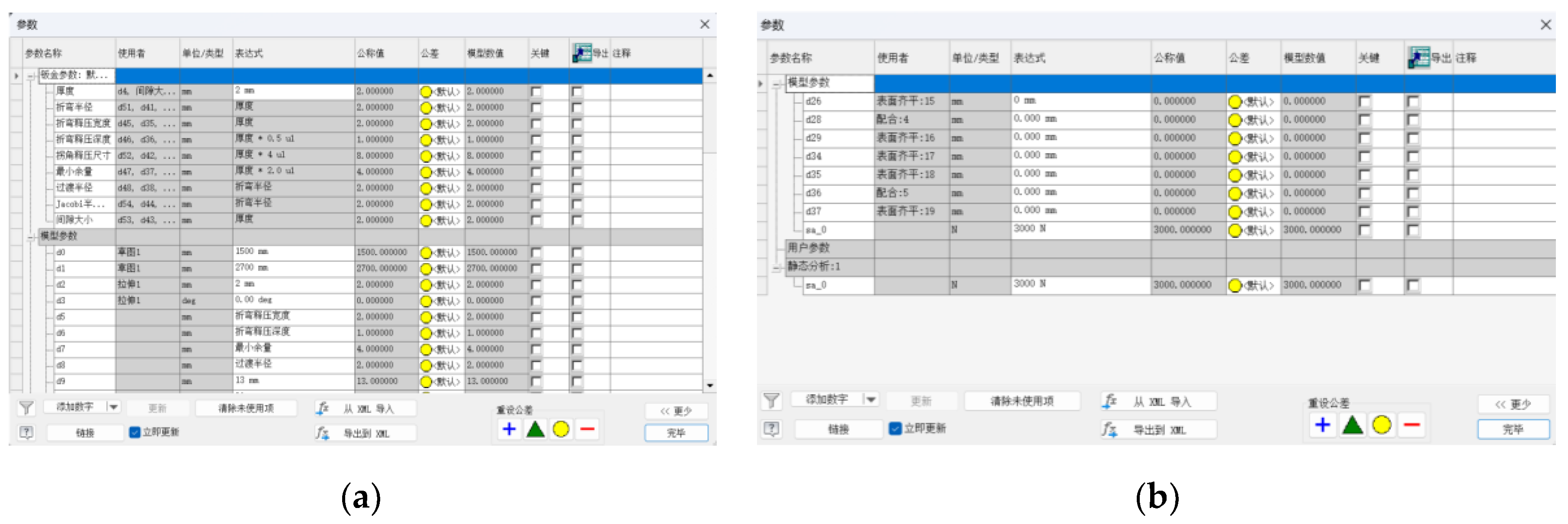
Figure 9.
Module transport for Magic Box 1.0 (a. concept b. Field photo).
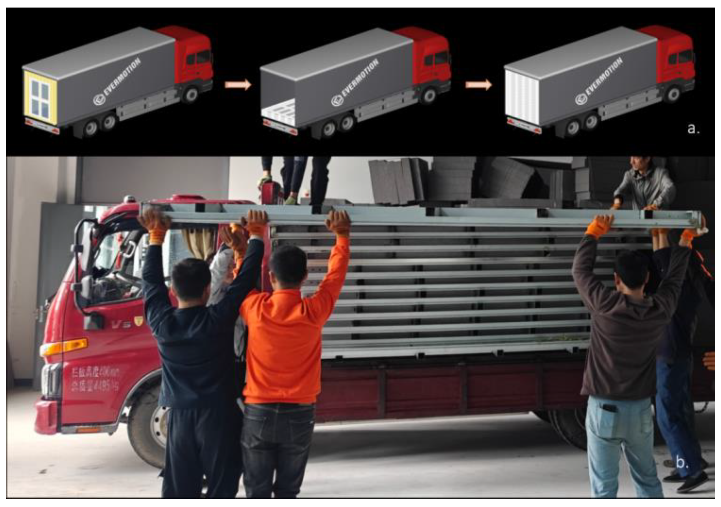
Figure 10.
DFC plumbing and electrical wiring optimization diagram.
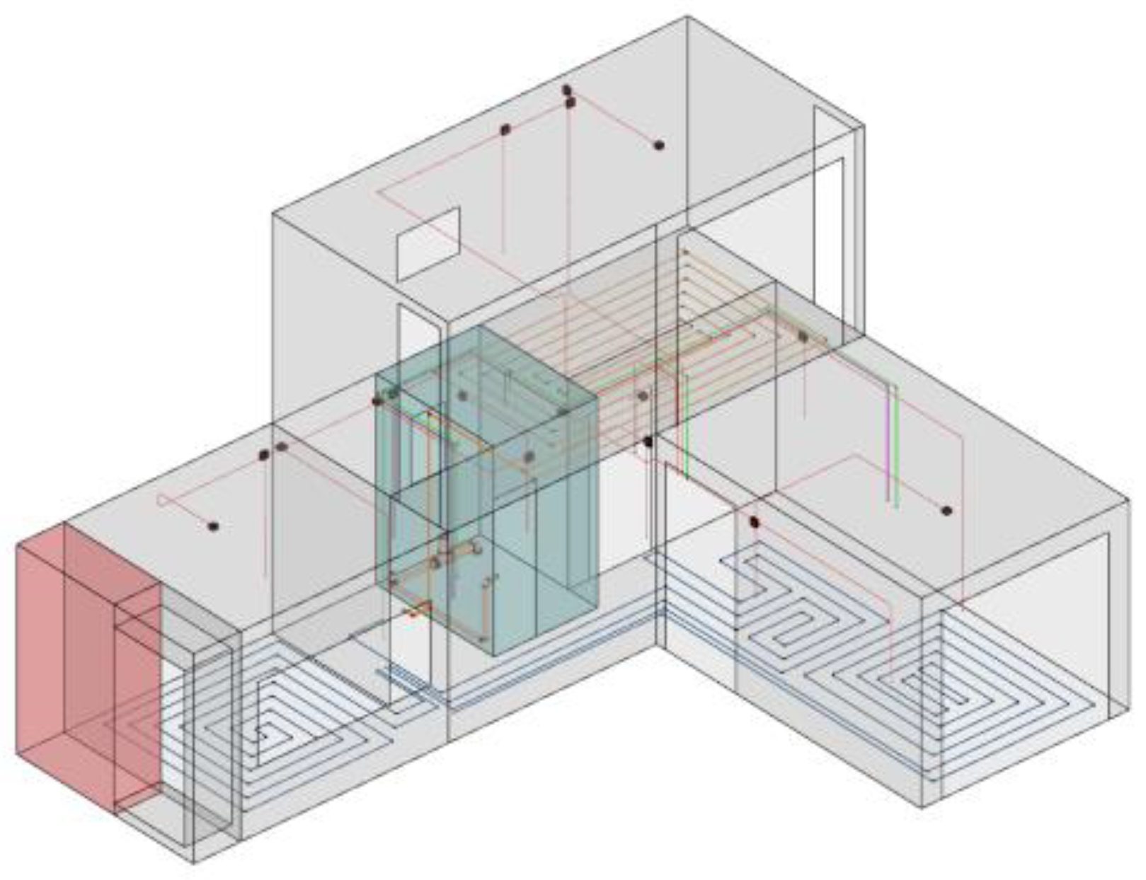
Figure 11.
Schematic diagram of sheet metal process nodes.
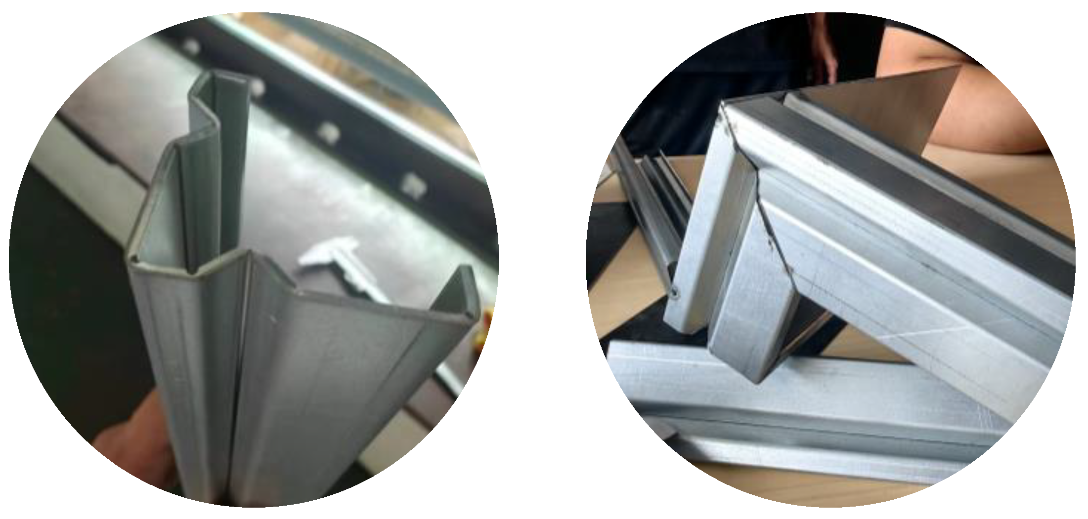
Figure 12.
Structural stress analysis results.
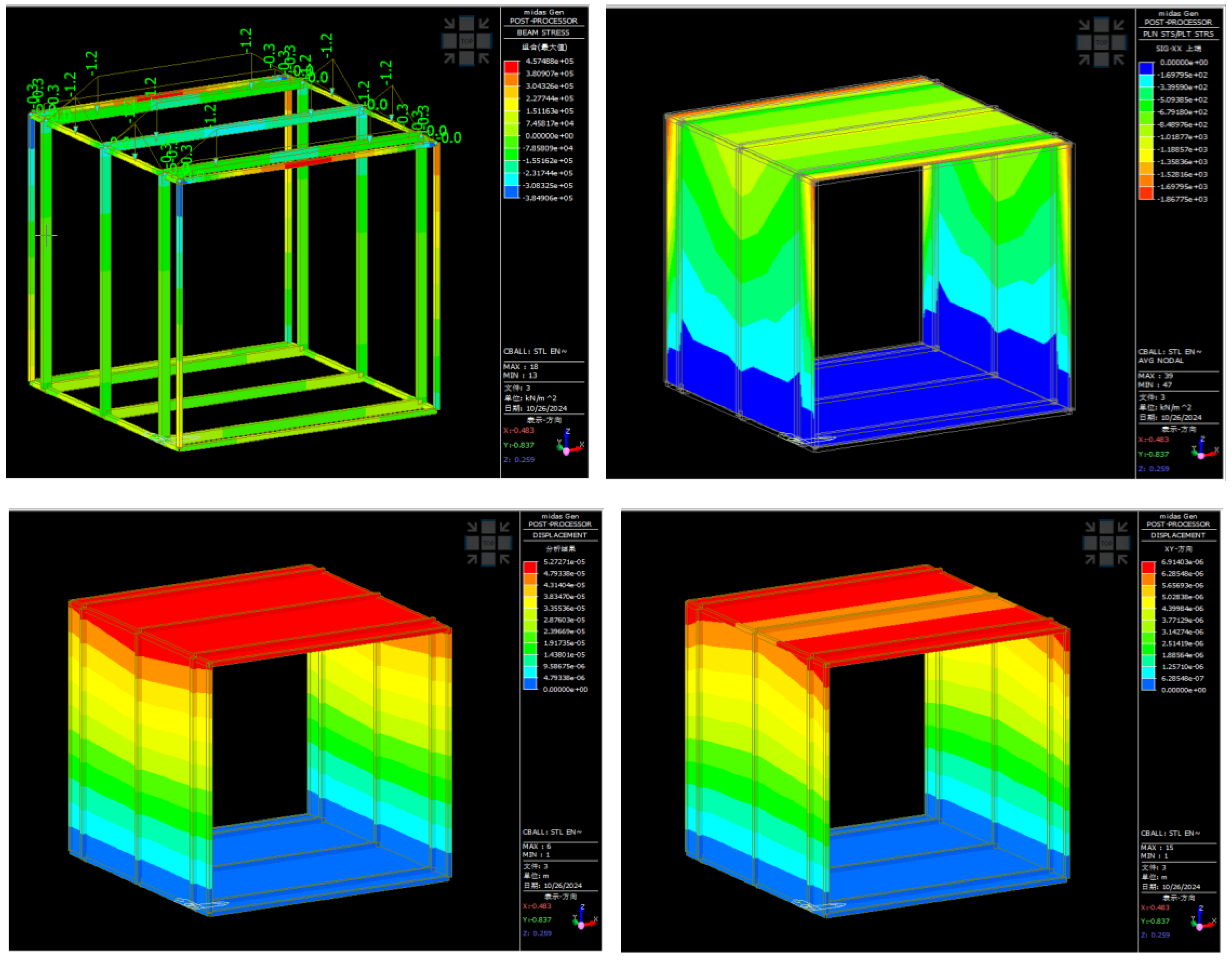
Figure 13.
Figure 13. diagram of the “exoskeleton” wall. (a) Longitudinal force diagram of the “exoskeleton” wall; (b)Transverse force diagram of the “exoskeleton” wall.
Figure 13.
Figure 13. diagram of the “exoskeleton” wall. (a) Longitudinal force diagram of the “exoskeleton” wall; (b)Transverse force diagram of the “exoskeleton” wall.
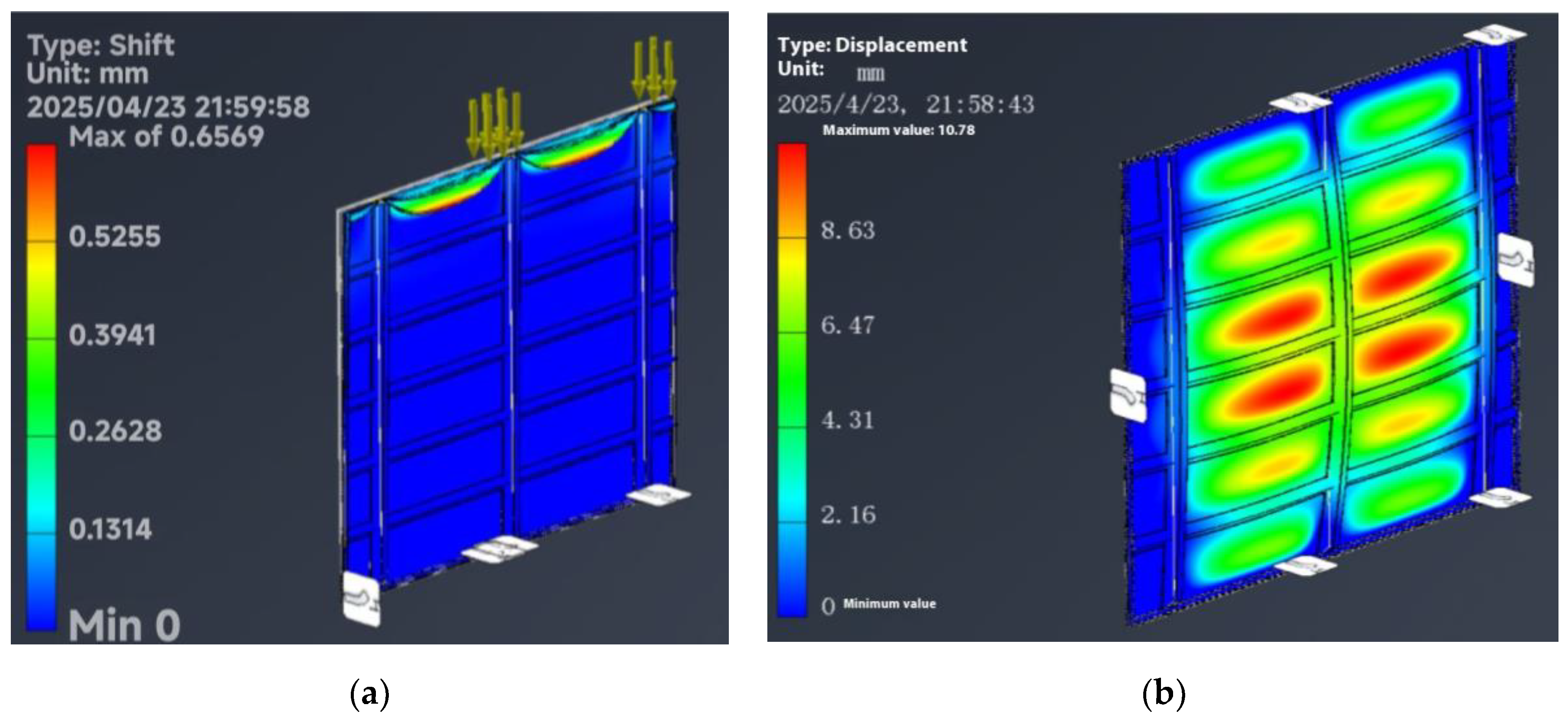
Figure 14.
Figure 14. Diagram of performance analysis. (a) M-Box 1.0 wind simulation analysis diagrams; (b)M-Box1.0 light simulation analysis diagram.
Figure 14.
Figure 14. Diagram of performance analysis. (a) M-Box 1.0 wind simulation analysis diagrams; (b)M-Box1.0 light simulation analysis diagram.
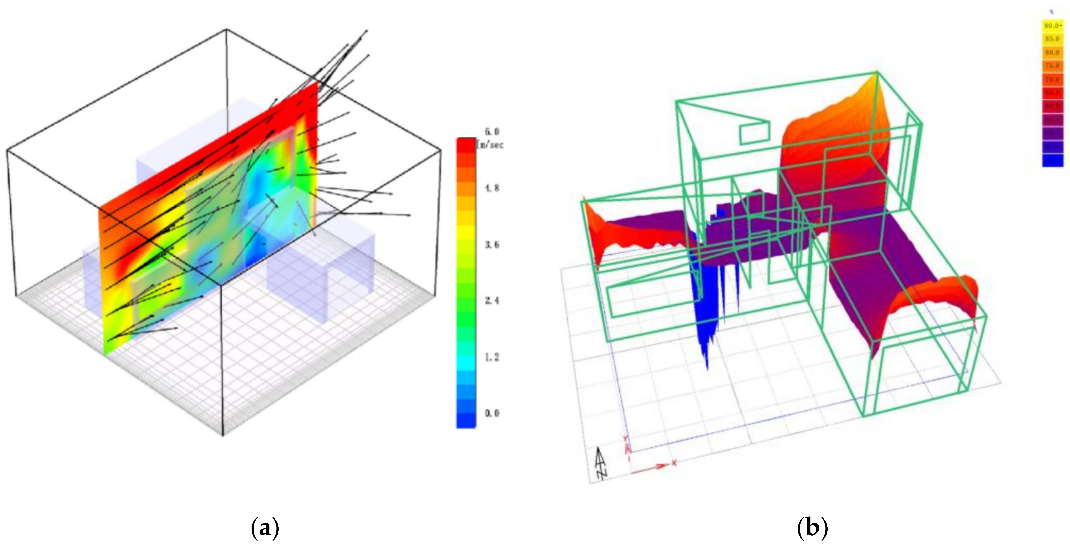

Table 1.
Comparison of the duration of M-Box 1.0 and steel buildings of the same size.
| M-Box1.0 | Steel buildings of the same size | |
|---|---|---|
| 1-Manufacturing time (days) | 11 | 3 |
| 2-Packing time (days) | 1 | 0.1 |
| 3-Transportation time (days) | 0.5 | 0.5 |
| 4-Assembly/construction time (days) | 2 | 14 |
| 5-Idle and waiting time (days) | 0 | 5 |
| 6-Total time (days) | 14.5 | 22.6 |
Table 2.
Cost Comparison of M-Box 1.0 and Same-Size Steel Buildings.
| Prices and Classification | M-Box1.0 | Steel buildings of the same size | |
|---|---|---|---|
| material cost | 1- Structural body | 10w(“exoskeleton” structure) | 13w(Steel structure) |
| 2-Interior finishes | 1w | 1w | |
| 3-Exterior finishes | 0.2w(painting/filming) | 2w(veneer) | |
| 4-Insulation | 1w | 1w | |
| 5-Plumbing | 1w | 1w | |
| 6-Kitchen and bathroom fixtures | 1.5w | 1.5w | |
| 7-Photovoltaics and energy storage | 2w | 2w | |
| 8-Furniture | 6w | 6w | |
| labor cost | 9-Fabrication | 3w | 0.2w |
| 10-Packing | 0.1w | 0 | |
| 11-Transportation | 0.1w | 0.1w | |
| 12-Assembly/building costs | 0.2w | 8w | |
| add up the total | 26.1w | 35.6w | |
Table 3.
Carbon emissions during the construction and building operation phases.
|
Carbon emissions during construction |
Material preparation (t.CO2) | 145.81 |
| Component production(tCO2) | 3.44 | |
| Transportation(t.CO2) | 5.08 | |
| Component assembly (t.CO2) | 2.91 | |
| Carbon emissions during operation | Clean energy(t.CO)2·y) | -32.11 |
| Building system energy consumption(t.CO2·y) | 3.09 |
Disclaimer/Publisher’s Note: The statements, opinions and data contained in all publications are solely those of the individual author(s) and contributor(s) and not of MDPI and/or the editor(s). MDPI and/or the editor(s) disclaim responsibility for any injury to people or property resulting from any ideas, methods, instructions or products referred to in the content. |
© 2025 by the authors. Licensee MDPI, Basel, Switzerland. This article is an open access article distributed under the terms and conditions of the Creative Commons Attribution (CC BY) license (http://creativecommons.org/licenses/by/4.0/).
Copyright: This open access article is published under a Creative Commons CC BY 4.0 license, which permit the free download, distribution, and reuse, provided that the author and preprint are cited in any reuse.


