Submitted:
15 July 2025
Posted:
18 July 2025
You are already at the latest version
Abstract
Reaching net-zero greenhouse gas emissions will require broad deployment of Carbon Capture and Storage (CCS), yet significant challenges remain. This paper reviews the main barriers that may hinder or delay widespread CCS adoption, drawing on current projects in various stages of planning, construction, and development. The discussion focuses on technical, economic, social, and regulatory aspects of CCS and identifies several key obstacles. These include the high financial burden on energy production, persistent uncertainties about the long-term behavior of stored CO2, and the complexity of the regulatory framework governing CCS projects and CO2 pipelines. Carbon capture, use, and storage (CCUS) remains a major focus of attention in the petroleum industry due to its potential to remove carbon dioxide from the atmosphere or prevent future emissions. Despite this potential, challenges and risks continue to limit progress.
Keywords:
carbon capture and storage
; CCS
; CCUS
; CO2 transport
; geological storage
; climate mitigation
; environmental risk
; sustainability
; public perception
; net-zero
; direct air capture (DAC)
1. Introduction
Carbon capture and storage (CCS) technologies have become central to efforts to mitigate climate change by reducing greenhouse gas (GHG) emissions, especially carbon dioxide (CO2). These technologies are increasingly integrated with industrial processes and power generation, forming the foundation of carbon capture, utilization, and storage (CCUS) when the captured CO2 is used in commercial applications such as enhanced oil recovery (EOR). In this paper, we will refer primarily to CCS, even when a utilization component is included. While some authors draw distinctions between terms like storage and sequestration, we treat them interchangeably and do not attempt to resolve this ongoing debate.
Our principal focus is on capturing CO2 from industrial sources and from Direct Air Capture (DAC), and on its long-term storage in geological formations. CCS and carbon dioxide removal (CDR) approaches are essential components of climate mitigation strategies, particularly for hard-to-decarbonize sectors such as steel, cement, and long-distance transport. DAC, in particular, has drawn attention as a means of extracting CO2 directly from the atmosphere. These systems use chemical sorbents or physical processes to isolate CO2 from ambient air, which can then be stored or used industrially. When DAC is combined with geological storage, it offers a viable route to net-negative emissions.
Several technologies are used for capturing CO2 from industrial point sources, including chemical absorption, adsorption, and membrane separation. Once captured, the CO2 is compressed and transported—usually by pipeline or, less commonly, by ship—to a suitable injection site. Geological storage targets include depleted oil and gas reservoirs, saline aquifers, and deep coal seams. When properly characterized and managed, these formations offer the potential for secure long-term storage of large volumes of CO2.
CCS also complements a broader set of CDR methods, which include biological approaches to increase carbon stocks in soils and biomass, geological enhancement techniques that bind CO2 into rock, and ocean-based methods [1] to increase dissolved or mineralized CO2 in marine environments. The National Academies of Sciences, Engineering, and Medicine has projected the need for more than 6 billion tonnes (Gt) of CO2 removal by 2050 to meet net-zero targets [2]. This is roughly equivalent to 16 percent of global emissions in 2023, which were 37.4 Gt (see Figure 1). Yet, despite increasing interest in CDR, none of the current approaches are on track to meet that scale.
Efforts to limit global warming to 1.5°C or 2°C above pre-industrial levels will require rapid and sustained reductions in CO2, methane (CH4), carbon monoxide (CO), and other GHGs. This includes widespread electrification, renewable energy deployment, improved efficiency, and the use of negative emission technologies such as CCS [3]. These mitigation pathways rely on technologies that reduce emissions at the source, as well as those that remove CO2 already present in the atmosphere.
CCUS also plays a role in retrofitting existing industrial and power plants. Estimates suggest that nearly 600 billion tonnes of CO2 emissions could be mitigated over the next 50 years through these approaches, an amount equal to nearly 17 years of emissions at current rates. Captured CO2 can also contribute to the production of synthetic fuels, particularly when combined with low-carbon hydrogen. These synthetic fuels are among the few options available for decarbonizing long-distance air and marine transport.
Despite its potential, the CCS field faces several persistent obstacles. Most existing projects have encountered cost overruns, delays, or underperformance in injection rates. The overall volume of captured CO2 is still small relative to the scale needed. Today, global CO2 use remains limited—approximately 230 million tonnes per year, of which 130 Mt are for urea production and about 80 Mt are used for EOR. Many direct uses of CO2, including synthetic fuel production, require an external hydrogen supply, which historically has been fossil-derived. Moving to low-carbon hydrogen sources (blue or green hydrogen) is essential to decarbonizing these applications [4]. Storage remains our primary focus because the scale of CDR requirements far exceeds the scale of potential CO2 uses. Nonetheless, both utilization and storage have roles to play in achieving net-zero. Figure 2 illustrates the distribution of over 18,000 peer-reviewed papers on “carbon capture,” highlighting the broad interdisciplinary engagement with this topic.
Chemical and petroleum engineers, in particular, have a substantial role to play in the development and deployment of CCS. Their expertise in subsurface engineering, reservoir characterization, injection, and project management is directly relevant to the challenges of secure storage. Their experience in EOR and large-scale fluid injection operations places them at the center of many CCS initiatives. CCS remains one of the most active and consequential research areas in the intersection of climate and energy.
2. Status
Even with aggressive reductions in fossil fuel use, electrification, and efficiency improvements, CCS must contribute between 3 and 6 gigatonnes (Gt) of CO2 reductions per year by 2050 to meet global climate goals As of 2022, progress remains far below that target. By September 2022, 30 commercial CCUS projects were in operation with a combined annual storage of 42.6 million tonnes (Mt) of CO2. Eleven additional projects were under construction, and more than 150 others were in various stages of development. The total capacity across all 196 announced projects reached just under 244 Mt per year (MTPY). That year also saw a resurgence in activity, with 20 new projects reaching final investment decision (FID).
Enthusiasm for CCS declined sharply during the 2014–2015 collapse in oil prices, but investment has accelerated through 2023. Global CCS investments dropped 50% in 2024 from 2023 levels largely driven by uncertainty of governmental support. The International Energy Agency (IEA) has scaled back its earlier ambitions but still targets 1,000 MTPY of CO2 capture by 2030—an almost fourfold increase from current levels. Achieving this will require substantial new infrastructure and investment.
While several major projects advertise large capacities, actual injection volumes remain lower as most are still ramping up. For example, the Alberta Carbon Trunk Line reports a design capacity of 14.6 MTPY, but injected only 1.865 Mt of CO2 across nine wells in 2022 [5]. In Brazil, Petrobras has reinjected over 10 Mt of CO2 per year from pre-salt offshore platforms in the Santos Basin, eliminating routine venting. As of 2024, global commercial CCS capacity is expected to reach about 45 Mt annually, distributed across 40 operating facilities. Although rapid growth is expected, CCS still falls well short of the trajectory needed to meet net-zero goals.
Historically, most CCS projects have been linked to natural gas processing. However, new development is shifting toward the power sector, hydrogen production, and industrial sources such as steel and cement [6]. While North America currently hosts the largest number of projects, the strongest near-term growth is expected in Europe. Figure 3 shows the distribution of capture facilities by sector, with a growing number of projects emerging outside traditional applications.
The pipeline of commercial projects has expanded rapidly. More than 30 commercial-scale facilities have been announced in just the past three years, with projects nearing FID representing around USD 27 billion in planned investment—twice the amount projected only six years ago [7]. This expansion reflects growing interest in applying CCS technologies to a broader set of industrial sectors.
Public funding for CCS has also increased substantially. From 2018 to 2023, the U.S. Department of Energy committed USD 1.4 billion across 654 research and development projects. The Bipartisan Infrastructure Law added another USD 2.537 billion for demonstration-scale capture initiatives. In addition to direct funding, the Inflation Reduction Act (IRA) significantly increased tax credits: up to USD 85 per tonne of CO2 permanently stored, and USD 60 per tonne for CO2 used in EOR or other industrial applications. DAC projects receive even higher subsidies—USD 180 per tonne for permanent storage and USD 130 per tonne for use. Total subsidies could exceed USD 30 billion, although estimates vary and remain uncertain.
As of March 2024, the United States accounted for 260 of the 564 CCS projects worldwide. Several other countries have launched major efforts. In Europe, Denmark, Norway, the Netherlands, and the United Kingdom have national CCS strategies and are developing cross-border agreements for transporting and storing CO2. A notable example is the 2021 cooperation between Norway and the Netherlands for CO2 storage in the North Sea.
Significant activity is also underway in China, which has supported CCS with major research programs and numerous patent filings. Canada has combined national subsidies—including a USD 1.84 billion tax credit—with provincial incentives for CCS. Other countries with ongoing CCS initiatives include Australia, Malaysia, and Indonesia.
In contrast to the U.S. approach, which has relied almost entirely on incentives, most countries combine subsidies with penalties for emissions through carbon taxes or cap-and-trade systems. This mixed approach may create stronger incentives for sustained deployment and long-term commitment to CCS technologies.
3. Challenges Remain
While widespread CCS at scale is essential to achieving climate goals, even the most enthusiastic proponents acknowledge multiple challenges ahead. Opponents of CCS are quite vocal and claim that drawbacks of CCS far outweigh the benefits. Despite receiving nearly USD 4 billion in combined government and industry commitments towards CCS, along with substantial government support from initiatives like 45Q in the US, numerous technical and financial risks persist. However, CCS finds itself in a considerably stronger position to contribute to sustainable recoveries compared to its status following the 2008-09 global financial crisis. Deployment has tripled, albeit from a modest starting point, demonstrating an expanded range of applications, decreased costs, and the emergence of new business models since that time. We categorize these challenges and risks as follows:
- Technological Challenges: These include energy use, capture efficiency, storage integrity, transportation, and infrastructure, and limited “use” applications.
- Economics and Financial Risks: Reducing capital and operating costs, addressing long-term liabilities, uncertainty of revenue streams, and carbon pricing/taxation.
- Regulatory and Policy Risks: Potential for shifting regulatory support, absence or inadequacy of carbon pricing, tax incentives or subsidies, authorization of permits, requirements for monitoring and actions, and long-term liabilities.
- Environmental and Safety Risks: Geological risks including assessing and mitigating geological risks associated with CO2 storage, such as potential leakage from various routes, induced seismicity, and subsurface interactions. Minimizing ecological impacts of CCS projects on terrestrial and aquatic ecosystems, including effects on biodiversity, water quality, and land use.
- Public Perception and Social Risk: The perception that CCS exists primarily to extend the commercial life of oil and gas activity, the NIMBY and BANANA problem, public skepticism, or opposition due to concerns about safety, environmental impacts, and reliance on fossil fuels. “Not in my back yard” or NIMBY refers to opposition to projects near ones residence while “build absolutely nothing near anybody” or BANANA refers to people who oppose almost any new project.
- Challenges with community engagement to ensure transparency, address concerns, and secure social license for CCS projects, particularly regarding site selection and environmental impact assessments. Social equity concerns also remain.
- Startup and Scaleup Risks: Costs and performance of first-of-a-kind (FOAK) facilities have often been problematic and challenges for implementing nth-of-a-kind (NOAK) facilities will continue to the degree that each facility needs to have bespoke design characteristics. Massive cost reductions in wind and solar power generation costs and batteries have occurred with widespread commercial adoption, manufacturing efficiencies and rapid technological improvements. The pace of cost reductions in the scaleup of CCS is likely to be much less pronounced.
4. Technological Challenges
Technological problems occur across the range of CCS projects including capture, transportation, and storage. The bulk of current research focuses on improving technological issues in carbon capture including capture efficiency, energy use, solvent loss and cost reduction. Other research on modularization addresses both scale-up and cost issues. Storage technological challenges
4.0.1. Capture Efficiency
While the technology to extract CO2 from natural gas streams is not new, developing efficient and cost-effective capture technologies capable of capturing CO2 emissions from various industrial processes and power plants remains a challenge. Most existing projects use pre-combustion capture and amine absorption. Promising new technologies include adsorption onto metal-organic frameworks (MOF) or others along with cryogenics, chemical looping, and membranes.
Carbon capture has focused on natural gas processing, industrial applications, fossil fuel and biofuel power generation, and carbon dioxide removal. The industry has a great deal of experience in natural gas processing because non-hydrocarbon diluents in the gas above certain limits must be removed in order to sell the product. Removal of CO2 and H2S by amine absorption and several other technologies for these applications was matured over decades; however, captured CO2 was often vented to the atmosphere but when high volumes are available was used in EOR. There are a wide range of industrial applications that generate CO2. CCS is being tested as a solution for hard-to-abate industries such as coal and steel along with a variety of chemical processes including ethanol and fertilizer production. Power generation applications are primarily post-combustion processes. The concentration of CO2 varies from about 4
Broadly, carbon capture technologies can be grouped as follows (Figure 4):
- Liquid solvents including established technologies like amine solvents used in natural gas processing, fertilizers, etc., physical solvents (e.g. Solexol, Rectisol) which do not have chemical reactions like amines, the Benfield process and its variants in which thermally regenerated, cyclical solvent process that uses an activated, inhibited hot potassium carbonate solution to remove CO2. Other liquid solvent technologies that are not fully commercial include chilled ammonia, phase change solvents, amino-acid-based solvents and water-lean solvents. Other technologies are under research stage activities.
- Commercial solid adsorbents include pressure swing/vacuum swing absorbents. Temperature swing adsorbents, enzyme-catalyzed adsorbents and sorbent-enhanced water gas shift are being piloted along with other technologies under development.
- Gas separation membranes for natural gas processing are commercial such as in the Petrobras Santos Basin Pre-Salt Oil Field CCS. Many other membrane technologies are under rapid development and pilot scale testing along with others at research and bench scale evaluation. Polymeric, electrochemical, cryogenic, solvent and room temperature membrane research are underway.
- Solid looping technologies including chemical and calcium looping are at various pilot stages.
- Inherent CO2 capture such as the Allam-Fetvedt Cycle has been demonstrated at the Netpower facility in la Porte, TX and the Calix Advanced Calciner pilot LEILAC.
- Post-Combustion Capture involves capturing CO2 emissions after the combustion of fossil fuels, typically from the flue gas of power plants or industrial facilities. Absorption solvents, such as amines or ammonia, are used to selectively capture CO2 from flue gas streams. The captured CO2 is then separated from the solvent, purified, and compressed for transport and storage. Major technical challenges include the energy-intensive nature of solvent regeneration, which can increase the overall energy consumption of the plant. Additionally, solvent degradation, corrosion, and solvent emissions are concerns that need to be addressed to ensure efficient and reliable operation.
- Pre-Combustion Capture involves capturing CO2 before combustion occurs by converting fossil fuels into syngas (a mixture of hydrogen and carbon monoxide) through gasification or reforming processes. In pre-combustion capture, CO2 is separated from the syngas before combustion using techniques such as pressure swing adsorption (PSA) or physical solvents. The remaining hydrogen-rich syngas can then be used as a fuel or feedstock. Technical challenges include the complexity and cost of gasification or reforming processes, as well as the need for reliable CO2 separation technologies. Efficient integration with existing power or industrial plants also presents challenges.
- Oxy-fuel combustion involves burning fossil fuels in a mixture of oxygen and recycled flue gas, resulting in a flue gas stream consisting mainly of CO2 and water vapor. By using oxygen instead of air, the resulting flue gas primarily comprises CO2 and water vapor simplifying the separation process. Technical challenges include the high cost and energy intensity of oxygen production, as well as the development of reliable and cost-effective CO2 separation technologies. Ensuring the purity of the CO2 stream and minimizing energy penalties are also important considerations.
Overall, the major technical challenges facing carbon capture technologies include reducing energy consumption and costs, improving efficiency and reliability, addressing environmental and safety concerns, and scaling up these technologies for widespread deployment. Continued research, development, and innovation are essential to overcoming these challenges and advancing carbon capture technologies towards commercial viability and widespread adoption.
Some technological problems are so severe as to collapse the entire project. The Southern company Kemper project attempted to commercialize coal gasification coupled with CO2 capture and failed due to a variety of technical and operational issues. Startups and delays associated with carbon capture have plagued many FOAK projects.
4.0.2. Energy Requirements
Addressing the energy requirements of CCS processes, carbon capture and compression can consume significant amounts of energy, potentially offsetting some of the emissions reductions achieved. Every step in each process of CCS has a thermodynamic efficiency less than unity. Few existing CCS projects use electricity from renewable power; many future ones plan to do so.
4.1. Transportation Infrastructure
There are substantial regulatory and permitting challenges along with issues on public acceptance of new transportation infrastructure. It is possible to ship CO2 via trucks, rail, or ship but pipelines are by far the most cost-effective and safest technology to use. The US has more than 8,000 km of pipelines, about 85% of global capacity and transports more than 70 MTPY of CO2 via pipeline. Only ship infrastructure requires significant technological improvements. Only about 3MTPY of CO2 is transported by ships. Although the petroleum industry has decades of experience in operating high-pressure CO2 pipelines, major challenges remain. Establishing and maintaining a dedicated pipeline infrastructure for CO2 transport is essential because sources of CO2 emissions are infrequently located and sized such that no pipeline would be needed. Economic considerations favor large storage sites and gathering from multiple emission sites in a network or hub approach. Pumping dense phase CO2 pipelines requires high-pressure conditions. Corrosion from CO2 and impurities is technically challenging. Ensuring the integrity and reliability of pipelines over long distances, especially in challenging terrains or offshore environments, requires advanced engineering and monitoring systems. None of these technological challenges are insurmountable.
CO2 must be compressed to high pressures for efficient transportation, which demands significant energy input and specialized compression equipment. Dense phase CO2 requires specialized pumps and ensuring the safe handling and containment of pressurized CO2 throughout the transportation process is vital to prevent leaks or accidents. Managing risks associated with transporting CO2, including the potential for leaks, spills, or pipeline ruptures, requires robust safety protocols and emergency response plans. Minimizing the environmental and health impacts of CO2 releases during transportation necessitates stringent safety measures and monitoring systems.
Achieving cost-effective CO2 transport solutions is challenging due to the high capital investment required for pipeline construction, operation, and maintenance. Optimizing transportation routes, pipeline capacity, and operational efficiency to minimize costs while maximizing CO2 delivery is a continuous challenge.
Navigating regulatory requirements and obtaining permits for CO2 transportation projects can be complex and time-consuming, involving multiple stakeholders and compliance with environmental, safety, and land use regulations. Community relations and stakeholder engagement for CCS pipelines will need to go well beyond local residents as people from far away from the proposed pipeline area may organize opposition to such new construction. Although the safety record for pipelines has been good, accidents like the Satartia, MS incident in 2020 are used to oppose any new activity. Meeting the scale and volume demands of CO2 transport, especially for large-scale capture and storage projects or industrial applications, requires extensive planning and coordination to ensure adequate capacity and logistics. Opposition to new pipelines may be intense as exemplified in a subsequent discussion of the Navigator Heartland Greenway CO2 Pipeline Project.
One major advantage of DAC coupled with CCS is that the DAC facility can be located at the storage or use site. Another is that unlike a capture project whose inputs depend on the emissions from one or more industrial or power generating plants, the concentration of CO2 in the air is not highly variable over months or years.
Coordinating CO2 transport with capture and storage systems involves technical challenges related to interface compatibility, storage site selection, and operational synchronization to optimize overall system performance and efficiency. Addressing these technological challenges requires interdisciplinary collaboration among engineers, scientists, regulators, and industry stakeholders to develop innovative solutions, enhance safety standards, and facilitate the widespread deployment of CO2transport infrastructure essential for carbon capture, utilization, and storage initiatives.
5. Storage Integrity and Injectivity
Ensuring the integrity and long-term stability of CO2storage sites to prevent leakage and ensure safe containment of captured carbon. Many petroleum engineers and earth scientists focus almost exclusively on storage where injection of CO2 is primarily for either EOR or permanent storage. Storage reservoirs include saline aquifers, depleted oil and gas fields, and basalt formations. Other ideas including unmineable coal deposits have fallen out of favor. Most current CCS projects focus on EOR while most planned projects target saline aquifers.
EOR projects are attractive because we have used CO2 injection for decades for miscible or immiscible displacement of oil and have been particularly successful in the Permian Basin where about 2/3rds of CO2 EOR production is located. Further potential in residual oil zones and for unconventional reservoirs is substantial. Some potential exists for offshore applications. Operators have historically had to purchase CO2 and have operated EOR projects in a way to recover as much of the injected CO2 as possible for recycling and reuse. It is possible to operate EOR projects to sequester much of the injected CO2 and contribute to CDR goals. In the US, injection permits for CO2 for EOR (Class II) are much easier to obtain than permits required for CCS projects (Class VI). CCS costs and requirements for metallurgy, reservoir characterization and MRV are also higher. In part, this is because producing wells in EOR projects serve as pressure sinks making it less likely for out of formation migration of CO2. While storing CO2 for use in EOR may decrease atmospheric emissions, emissions from production and combustion of commercially produced oil associated with such projects are higher than the reduction due to storage.
5.1. Saline Aquifers
Saline aquifers are the target for most dedicated storage projects underway in part because there are so many of them. The United States Geological Survey (USGS) [8] estimated there were 3,000 Gt of technically accessible storage resources in the US alone. The Oil and Gas Climate Initiative (OGCI) estimated nearly 14,000 Gt of storage resources, 97% of which were in saline aquifers. Saline aquifers are often thick, permeable, and laterally continuous. Unlike existing oil and gas fields that have numerous wellbore penetrations, most aquifers are relatively poorly characterized from a geological, geophysical, geomechanical, and engineering point of view. Additionally, the pore space in saline aquifers is already full of water, a very slightly compressible fluid. Unless massive volumes of water are to be produced from the target aquifer along with CO2 injection, there will be an increase in reservoir pressure (and effective stress) in such reservoirs creating the possibility of microseismic emissions and escape of CO2 along faults or natural fractures [9]. As saline aquifers may not be sufficiently well characterized, plume migration may not conform to initial estimates leading to a lack of long-term containment or the volumes available for storage may be much less than estimates.
This was the case in the Snøhvit CCS project [10] where reservoir pressure in the Tubåen formation rose much faster than anticipated by reservoir models predicted. The original plans called for injecting into the Tubåen for 18 years, but after four years, injection was changed to the Sto formation.
5.2. Depleted Oil and Gas Fields
There are more than 25,000 oil and gas fields in the world with the largest 1,500 accounting for 94% of global reserves and production [11]. Many of these fields have recovered more than 90% of their ultimate recovery and could be considered for CCS projects. We refer to depleted reservoirs based on their having recovered hydrocarbons to a point approaching the economic limit as opposed to pressure depletion. For consideration as a commercial carbon storage project, a depleted field should be at a sufficient depth (pressure and temperature) where CO2 can be stored as a dense phase. It should be large enough to store large volumes of CO2 without the risk of out-of-zone migration. High-quality oil reservoirs tend to have high permeability and porosity along with lateral continuity. In oil fields with these characteristics, there is almost invariably a water drive and/or water injection project that leaves the reservoir at a pressure close to the initial reservoir pressure if not as close to the frac gradient as possible. Depleted high-quality reservoirs are thus not usually pressure depleted. Some oil reservoirs are pressure depleted late in life and tend to have low permeability and may be laterally and vertically discontinuous. Such reservoirs are much less susceptible to waterflooding and are unlikely to be good candidates for CCS projects. Good quality depleted gas fields may not have extensive water drives and thus may be pressure depleted. If the pressure of such fields is below the critical point of CO2, injected CO2may remain in vapor phase until reservoir pressures increase. In such cases, injected CO2 will reach reservoir boundaries rapidly and present additional challenges.
One advantage of depleted oil and gas fields is that they are generally well characterized. Most large fields with numerous well penetrations have excellent petrophysical characterization and have often been modeled for reservoir simulation. Proper reservoir descriptions for such work provide an excellent head start for the reservoir characterization required for CCS. The major disadvantage for depleted reservoirs is the number of well penetrations, each of which provides a potential for leakage. Older fields may have abandoned wellbores penetrating the target formation with abandonments that while fit for purpose at the time are inadequate for CCS applications. US requirements for such fields require very detailed and often costly work to ensure that leakage is highly improbable.
6. Economics and Financial Risks
The world is undoubtedly better off if it can achieve substantial reductions in GHG emissions at an appropriate cost. Estimates of the negative effect of continued emissions at current levels vary widely and macro-economic models that attempt to put a value on CCS yield widely varying results [12]. Global economies are not set up to reward companies (or countries) for acting in the common good or punishing those who do not. Firms seek to maximize the utility of their stakeholders. Society, as represented by governments, regulates emissions to varying degrees, using a combination of carrots and sticks. Many countries have carbon prices, taxes, regulations, and incentives which vary widely [13,14,15,16,17,18].
High Capital Costs: CCS projects often entail high upfront capital costs, including expenses related to capture, transportation, and storage infrastructure, which may pose financial barriers to widespread implementation. This is particularly true for FOAK projects, but we do not have enough experience with repeated projects to conclude that costs for capture or storage are likely to be reduced dramatically and certainly not as rapidly as costs of solar, wind and battery technology. In a subsequent section describing startup challenges and unsuccessful attempts for CCS projects, excess costs have plagued most new projects. Low-cost finance may be possible through Master Limited Partnerships, private activity bonds, loan guarantees and other mechanisms [19].
Uncertain Revenue Streams: Uncertainty surrounding revenue streams, including carbon pricing mechanisms or incentives, can deter investment in CCS projects and hinder their economic viability. There is no global pricing mechanism or even subsidies and the US 45Q tax incentives are insufficient to cover the costs of the full value chain except for the most attractive propositions. Additional incentives or regulatory requirements such as regulatory restriction or taxes on emissions, capital grants for projects and/or opportunities to generate revenue from CO2 will be needed.
Operational Costs: Managing ongoing operational costs, including maintenance, monitoring, and site remediation, can impact the economic feasibility of CCS projects over their lifecycle. Ultimately, operators will expect to transfer their obligations and long-term risks to a sovereign such as state or federal bodies. Obligations to monitor CCS projects after the cessation of injection along with obligations to mitigate any migration of CO2 escaping the storage reservoir(s) is typically limited to a few decades up to 50 years or more. Fortunately, few project scenarios that do not have problems at 50 years are likely to develop them over the longer term. In fact, other CO2 behaviors increase stability over the long-term.
7. Regulatory and Policy Risks
Regulatory Uncertainty: Shifting regulatory frameworks and evolving environmental policies may introduce uncertainty regarding the long-term viability and profitability of CCS projects, affecting investor confidence. There have been few incidents of significant emissions, safety hazards or seismic activity to date with CCS projects. Should one or more such incidents occur it is reasonable to expect increased scrutiny and regulation along with increased difficulty in obtaining permits. EPA permits for Class VI injection wells have been multi-year efforts but are improving; this could change overnight due to policy changes or in response to events.
Policy Support: The absence or inadequacy of supportive policies, such as carbon pricing mechanisms, tax incentives, or subsidies, can impede commercial deployment of CCS technologies by failing to incentivize emissions reductions. US policy incentives are highly attractive now but an “all carrots, no sticks” model is not viable in the long-term. Ultimately, some form of regulatory requirements taxes or carbon pricing will be required. Regardless of how it is implemented, the policy and regulatory drivers resulting in widespread adoption of CCS will increase the cost to consumers of electric power, cement, steel and many forms of transportation.
8. Environmental and Safety Risks
Geological Risks: Assessing and mitigating geological risks associated with CO2 storage, such as potential leakage, induced seismicity, and subsurface interactions, to safeguard the environment and human health. Most new CCS projects saline aquifers in approximately normally pressured reservoirs. Injecting dense phase CO2 into such reservoirs will increase pore pressure and stresses with the potential for seismic activity and CO2 migration along faults or fractures. Such reservoirs are rarely characterized as well as oil or gas reservoirs with numerous wellbore penetrations and as a result, reservoir heterogeneities are likely to lead to plume growth different than originally anticipated and/or migration to other zones. While not completely unanticipated, such impacts have impacted even successful projects like Snøhvit and Sleipner.
Ecological Impacts: Understanding and minimizing potential ecological impacts of CCS projects on terrestrial and aquatic ecosystems, including effects on biodiversity, water quality, and land use.
9. Public Perception and Social Risk
Public Perception: Addressing public perception and garnering social acceptance of CCS technologies, which may face skepticism or opposition due to concerns about safety, environmental impacts, and reliance on fossil fuels. Many projects use captured CO2 for EOR. A surprisingly large number of people oppose CCUS for that specific reason, viz. that it increases the ultimate recovery of oil which will be consumed and generate substantially more carbon emissions than those saved by storing the captured CO2. This viewpoint fails under logical examination. Global crude oil consumption doesn’t go up because of added production from EOR. Oil produced using EOR is relatively expensive compared to the lowest-cost production but still less expensive than the highest marginal cost production. Nonetheless, opponents of CCUS seem to think it is a technology designed primarily to extend the commercial life of the oil and gas industry.
Opposition to large-scale projects near people’s homes is common across many industrial sectors despite potential benefits in employment or tax revenues, the so-called “Not in my backyard” or NIMBY problem. Increasingly, people who might live relatively far from such new projects actively oppose any new CCS developments and other projects including wind and solar. This is the “build absolutely nothing near anybody” or BANANA problem.
Community Engagement: Engaging with local communities and stakeholders to ensure transparency, address concerns, and secure social license for CCS projects, particularly regarding site selection and environmental impact assessments. Essentially, every successful project will need to go “above and beyond” to obtain the Social License to Operate for CCS projects.
Social Equity: Equity concerns also remain and vary globally. Most of the efforts directed toward CCUS have been focused on technology, finance, engineering, geology, etc. Social equity concerns include resource utilization, health impacts, safety, and economic impacts on all groups of people. Will land, resource, and energy use for CCUS raise prices or impact access for the poorest in the community? Minority, indigenous, and economically disadvantaged people have a long history of suffering greater health and safety impacts from industrial activity. Will new job opportunities align with the needs of potentially displaced fossil fuel workers? Who owns the technologies being deployed?
One summary of basic principles is as follows [20]:
Social equity means that the benefits of carbon removal must be equitably distributed. “Projects should reflect local concerns and contexts—including racial disparities and the historical exclusion of vulnerable communities from benefits and opportunities—in all research and deployment strategies. Project goals and outcomes should be shaped and informed by communities to ensure that concerns and contexts are being accurately represented.”
Community-developed safeguards are needed to ensure adverse impacts are not borne by vulnerable communities. Carbon removal solutions should not only avoid creating new adverse impacts but aim to redress the harms, pollution, and burdens already placed on frontline communities. Public engagement must be thorough, and comprehensive, and influence project outcomes. Communities must be well equipped with accessible and transparent information and tools, as well as the power to take ownership of decision-making in deployment strategies.”
10. Example Startup and Performance Issues
Many of the earliest CCS projects can be classified as pilots or demonstration projects and were never designed to be profitable. Many such projects failed to get off the ground and others had operational problems of varying degrees. In this section, we briefly discuss several projects to illustrate the range and variability of challenges that have occurred. Many of these startup complexities had to do with capture issues, regulatory concerns, and FOAK challenges. Some of the capture concerns were mitigated easily while others remain challenges.
In Salah (Algeria): This project commenced in 2004 [21] with a design goal of storing 1 to 1.2 MTPY of CO2 obtained by processing natural gas from the In Salah field which contained about 5.5-10.0 % CO2. The deep Carboniferous sandstone unit, initially assessed with an estimated storage capacity of 17 Mt, saw only 3.8 Mt CO2 stored during the six-year lifespan of the project [22]. Early into the injection phase, an increase in seismic activity within the region was observed, correlating to some degree with the CO2 injection process. This may have been due to migration within the storage formation itself [23]. Concerns regarding the association between seismic events and CCS technology safety prompted a cessation of injection. Various hypotheses, including fault leakage and hydraulic fracturing induced by injection pressures, have been proposed to explain observed pressure, seismic, and surface deformation patterns [24,25] There is no evidence indicating compromise of the overall storage complex, with multiple independent datasets affirming CO2 confinement within the containment zone.
Surface uplift has been recorded across all three In Salah CO2 injection wells, accompanied by corresponding subsidence over the gas production area [26]. It is theorized that before March 2006, when injection pressure reached its maximum, the observed surface response stemmed from CO2 injection-triggered tensile opening of a non-sealing fault zone and subsequent restrained expansion within the C10 formation [27]. The project was reported to have cost USD 2.7 billion. Extensive monitoring, measuring, and verification (MMV) technologies were deployed which anticipated various problems with seal and well integrity avoiding any leakage.
Gorgon (Australia): The Barrow Island gas plant was constructed to process natural gas from two offshore fields with significant concentrations of CO2. CO2 removal is by an amine scrubber with recovered CO2 which was then to be injected into a saline aquifer at a depth of 2500 m. Pressure in the target aquifer is to be reduced/managed by water production wells; water produced from the target reservoir can then be reinjected into shallower zones. Gorgon was planned to capture and store up to 4 MTPY or more than 100 Mt over its life reducing greenhouse gas (GHG) emissions from the Gorgon project by approximately 40% [28]. Gas production at Gorgon started in March 2016 with CO2 injection beginning in August 2019. Corrosion and leaking valves along with excess water in the pipeline from the LNG plant to the injection wells were identified as part of the delay. Significant loss of injectivity into shallow aquifer water disposal wells occurred in conjunction with unanticipated sand control problems. Gorgon has stored more than 6.6 Mt through July 2022 but has consistently underperformed expectations. As a result, the operator was required to acquire and surrender 5.23 million credible greenhouse gas offsets to meet its commitment to address a CO2 injection shortfall at Gorgon with the potential to require more such offsets in the future. Total investment is expected to exceed USD 3.2 billion.
Boundary Dam (Saskatchewan): This SaskPower [29] project is the longest-running carbon capture project at a coal-fired power plant and has cost more than 1.5 billion CDN. The previous coal-fired plant emitted 1.15 MTPY of CO2. The Boundary Dam project produces about 115 MW of power and experienced significant delays, operational challenges, and cost overruns and has been unable to reach the original target for capture and use in EOR at the Weyburn oilfield.
PetraNova (Texas): NRG Energy [30] and JX Nippon Oil & Gas Exploration Corp. built the Petra Nova carbon capture facility, expanding an existing NRG plant near Houston. Captured CO2 was exported to the West Ranch oilfield about 80 miles away for EOR. The US DOE provided 190 million USD in cost-sharing plus more than 200 million USD in low-interest loans for this project designed to capture 1.6 MTPY. The 1.0 billion USD project was completed on time and on budget in early 2017. EOR response at West Field was rapid and significant. Operational challenges include outages at the coal plant, CO2 pipeline shutdowns, export restrictions at West Ranch, and a Category 4 hurricane; however, the project recovered about 90% of target volumes. The project was shut down in May 2020 due to low oil prices. Subsequently, JX Nippon Oil & Gas Exploration purchased the remaining 50% stake from NRG Energy Inc. for $3.6 million. With the increase in oil prices, the project was restarted in late 2023 and functions well.
Sleipner (Norway): Sleipner field is one of the largest CCS projects storing 41 MTPY [31]. The project was commissioned in 1996 to store CO2 coming from the processed gas produced from the Sleipner West field in Norway which contains up to 9% CO2 (Davis, Landrø, and Wilson 2019). The primary aim of the project is to avoid paying NOK 1 million/day CO2 taxes. The carbon tax when Sleipner was 49 USD/tonne in 1996 while the cost of injecting CO2 was estimated to cost only 17 USD/tonne. The injection target is the Utsira formation, a huge saline aquifer with clean sandstone and attractive characteristics for CO2 storage [32].
There is no evidence of upward leakage to the surface in the traditional sense [33,34] but injected CO2 migrated higher than anticipated (around 220 meters) from the injection zone and seismic data suggest the presence of CO2 above the targeted storage zone [35]. These observations indicate CO2 migrated within the Utsira Sand formation itself, rather than escaping.
Another concern in Sleipner field injection sustainability is the source of CO2. Gas production of the Sleipner field has been on the decline since 2000 and production decline is such that it will be impossible to maintain 1 MTPY without new sources of CO2 [36]. Long-term viability will depend on sequestering carbon captures onshore from industrial sources and transported by ship or pipeline.
Shute Creek (Wyoming): The Shute Creek gas processing facility was commissioned in 1986 and processes gas produced in the LaBarge field containing 65% CO2 along with 21% CH4, 5% H2S, and 0.6% He29. Most of the produced CO2 was targeted to be used for EOR with about 400,000 TPY injected along with produced H2S. Total CO2 storage was expected to be more than 7 MTPY by 2010. However, there is no specific storage associated with Shute Creek other than the small amount associated with storing produced H2S. which operated under a “sell or vent” model. In 2008, the operator was selling about 225 MMcf/D of CO2 while venting 180 MMcf/D. In June of that year, regulators required reductions in emissions and the operator expanded the plant to capture more CO2. Oil prices during the 1986 price collapse fell and remained near or below 20$/bbl for more than a decade, greatly decreasing the economic case for EOR. A March 2022 report by the Institute for Energy Economics and Finance Analysis claims that about half of the produced CO2 since 1986 has been vented to the atmosphere. Performance greatly improved and achieved target recoveries for most of the 2014-2020 time period. In 2022, the BLM authorized another 60 MMcf/D of CO2 injection for permanent storage. In February 2022, ExxonMobil committed to a 400 million USD expansion which is to be operational by 2025.
11. Projects Failing to Proceed:
Dozens of projects have been canceled after extensive engineering, geological and financial efforts. While technical reasons are behind some of them, cost overruns and the lack of clear financial solutions are the dominant reasons. These are a few examples of such projects for illustration.
Kemper (Mississippi, US): This project [37,38,39] sought to capture emissions from a new plant designed to employ coal gasification to be burned for power generation along with capturing 3.3 MTPY of CO2. A variety of technical and operational issues drove project costs to increase from 3 to 7.5 billion USD and coal gasification was abandoned in favor of natural gas power generation and carbon capture plans were abandoned.
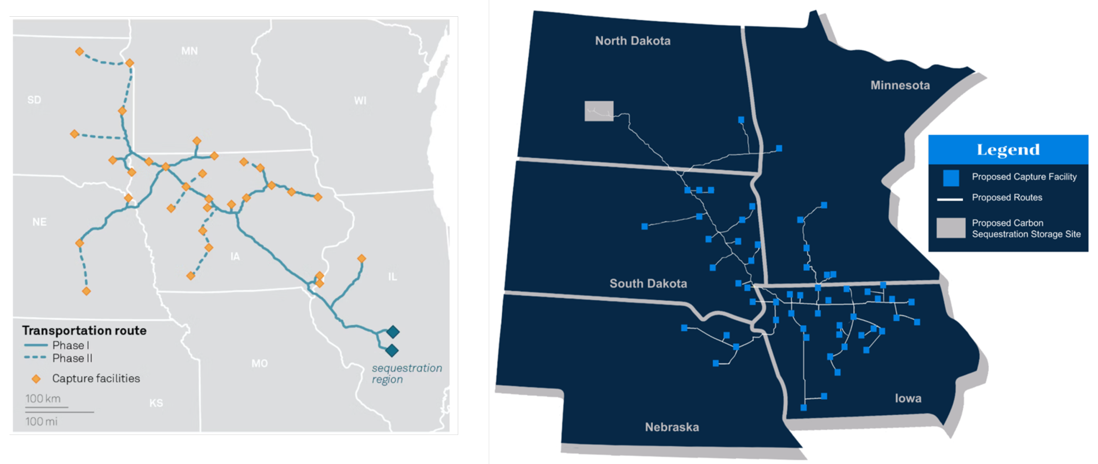
The Navigator Heartland Greenway CO2 Pipeline Project sought to build a 1,300 km CO2 pipeline to connect more than 21 ethanol and fertilizer plants across five midwestern states and transport produced CO2 to Illinois for permanent subsurface storage (Figure 5). The pipeline was estimated to cost 3.5 billion USD and enable a multi-state gathering and storage hub. Ethanol plants do not individually generate enough CO2 to justify storage projects but capturing CO2 from such facilities is relatively straightforward due to high concentrations. A large hub of such projects would be more attractive commercially. The use of carbon capture for ethanol could enable higher product prices when sold into markets with low carbon fuel standards including California, Oregon, Washington, and British Columbia. Low-carbon ethanol could be converted into Sustainable Aviation Fuel (SAF). Regulatory opposition to the pipeline was significant and Navigator canceled pipeline plans in October 2023 citing permitting issues, specifically “the unpredictable nature of the regulatory and government processes involved.”
The failure of one such effort doesn’t mean that the basic concept will not move forward. Two other projects remain active but face opposition and challenges. Summit Carbon Solutions is attempting to build another multi-state gathering hub (2,100 miles, 4.5 billion USD) to connect nearly 60 ethanol plants across Iowa, Minnesota, North Dakota, South Dakota, and Nebraska and store 16 MTPY of produced CO2 in North Dakota subsurface formations. While Summit has obtained more easements than Navigator did, the group faces opposition from multiple sources.
Similarly, Wolf Carbon Solutions is attempting to permit a 280-mile pipeline from Iowa to the Mt. Simon Hub in Illinois to transport CO2 on behalf of two ethanol facilities owned by Archer Daniels Midland Co. (ADM). In late 2023, Illinois Commerce Commission staff recommended that regulators deny the application. Wolf withdrew its permit application but plans to resubmit “in early 2024”.
The Mesaba Energy Project, initially proposed as a clean coal facility incorporating Integrated Gasification Combined Cycle (IGCC) technology, encountered insurmountable hurdles and was ultimately scrapped in 2007 [40]. The project succumbed to a blend of economic and regulatory impediments. Its viability was questioned due to “exorbitant” construction and operational expenses, prompting the Minnesota Public Utilities Commission to not approve a Power Purchase Agreement because it did not align with the state’s pursuit of the "least-cost resource". Environmental concerns concerning emissions raised by the Sierra Club also contributed to the project’s demise.
The FutureGen project was to retrofit Unit 4 at Ameren’s power plant in Meredosia, Illinois. Captured CO2 was to be injected into saline aquifers near Jacksonville in Morgan County, Illinois. FutureGen was awarded the first-ever EPA Class VI well injection permits in 2014 for four injection wells. The US-DOE terminated its agreement with the project in 2015, because of years of delays and the project’s inability to complete financing of the estimated 1.65 billion USD cost. Twenty percent of the one billion USD in federal funding had been disbursed.
The Antelope Valley project in North Dakota was to capture CO2 from a coal-fired power plant and the captured CO2 for EOR in Canada’s Weyburn field approximately 200 miles north in Saskatchewan. The US-DOE awarded the project 100 million USD with the USDA providing a 300 million USD loan. Basin Electric Power Cooperative withdrew its project from the program, citing regulatory uncertainty about capturing CO2, project costs, and environmental legislation.
Summit Power Texas Clean Energy Project. This proposal was to build a greenfield integrated coal gasification 400 MW power plant integrated with carbon capture and storage near Odessa, Texas [41]. The design spec to recover 90% of CO2 emissions would capture 2.7 MTPY and would be the largest fossil-fueled power plant with such recoveries. Captured CO2 would go to EOR projects in the region. The DOE supported the project with a $350 million cost-sharing award matched by the Clean Coal Power Initiative. A 2009 Texas law, HB 469, was passed which offered significant financial incentives to the first three clean-coal power plants built in Texas that capture at least 50 percent of their carbon dioxide. Chinese investors pulled out as estimated costs increased from 2.2 to 3.5 $billion USD and the project was abandoned.
The Indiana Gasification Project planned to capture CO2 from a coal gasification plant in Indiana for EOR in Texas and Mississippi. The project was canceled in 2015 because it was uneconomic.
Leucadia Lake Charles Project sought to capture 4.5 MTPY from a new methanol plant using co-generation coke-to-chemicals (methanol) plant. CO2 will be delivered to the West Hasting’s oil field in Texas for EOR via a 12-mile connector pipeline to an existing Denbury interstate CO2 pipeline. The project was awarded 1 $ billion USD of tax-exempt Gulf Opportunity-Zone Bonds (“GO Zone Bonds”) with a DOE contribution of 261 $million USD and another 368 $ million in private funding. Although canceled in 2014, another attempt to pursue the project attracted 2 $billion in conditional loan guarantees but has not advanced.
The Medicine Bow project was to be a coal-to-liquid power plant with CO2 capture proposed in Carbon County, Wyoming. The project would capture more than half of the CO2 produced during the coal refining process (3.6 MTPY) for EOR in Wyoming but was canceled as uneconomic.
12. Conclusions
Serious obstacles must be overcome before the technology of carbon, capture and storage can achieve multi-gigatonne global scale. Although numerous technical challenges remain, larger challenges deal with the economics of CCS. Because there are, outside of enhanced oil recovery, relatively modest use cases for CO2, substantial, indefinite, government subsidies, taxes, or carbon prices will be required. The costs of CCS will be reflected in individual and corporate tax burdens, energy costs and/or the costs of consumer goods and services. Alternative approaches to lowering carbon emissions may be more cost effective; however, achieving anything approaching net-zero emissions in the next 35 years will require widespread CCS. Each of the risks and obstacles identified in this paper must be addressed.
Funding
This research received no external funding.
Acknowledgments
During the preparation of this manuscript/study, the author used [ChatGPT, v4.o] for the purposes of formatting references and increasing resolution of one figure. The author has reviewed and edited the output and takes full responsibility for the content of this publication.
Conflicts of Interest
The author declares no conflicts of interest.
References
- National Academies of Sciences, E. Medicine. A Research Strategy for Ocean-based Carbon Dioxide Removal and Sequestration; The National Academies Press: Washington, DC, USA, 2022. [Google Scholar] [CrossRef]
- National Academies of Sciences, E. Medicine. Negative Emissions Technologies and Reliable Sequestration: A Research Agenda; The National Academies Press: Washington, DC, USA, 2019. [Google Scholar] [CrossRef]
- National Academies of Sciences, E. Medicine. Accelerating Decarbonization in the United States: Technology, Policy, and Societal Dimensions; The National Academies Press: Washington, DC, USA, 2023. [Google Scholar] [CrossRef]
- Meehan, D.N. Blue and Green Hydrogen in the Energy Transition. In Decarbonization Pathways for Oil and Gas; Oxford Institute for Energy Studies; University of Oxford: Oxford, UK, 2020. [Google Scholar]
- Inc., E.E.; Inc., W.C.S.; Partnership, N.W.R. Knowledge Sharing Report Division A: Summary Report CY 2022. Technical Report. 2023. Available online: https://open.alberta.ca/.
- Agency, I.E. Operating and Planned Facilities with CO2 Capture by Application. 2022. Available online: https://www.iea.org/data-and-statistics/charts/operating-and-planned-facilities-with-CO2- capture-by-application-2022.
- Global CCS Institute. Global Status of CCS Report 2023, 2023. Accessed 2024-03-15.
- Team, U.G.S.G.C.D.S.R.A. National assessment of geologic carbon dioxide storage resources—Results (ver. 1.1, September 2013). Technical Report Circular 1386, U.S. Geological Survey, 2013. Supersedes ver. 1.0 released June 26, 2013. 20 September.
- Zoback, M.D.; Gorelick, S.M. Earthquake triggering and large-scale geologic storage of carbon dioxide. Proceedings of the National Academy of Sciences of the United States of America (PNAS) 2012, 109, 10164–10168. [Google Scholar] [CrossRef] [PubMed]
- Simmenes, T.; Hansen, O.R.; Eiken, O.; Teige, G.M.G.; Hermanrud, C.; Johansen, S.; Nordgaard Bolaas, H.M.; Hansen, H. Importance of Pressure Management in CO2 Storage. In Proceedings of the Offshore Technology Conference, Houston, Texas, USA, May 2013. [Google Scholar] [CrossRef]
- Ivanhoe, L.; Leckie, G. Global oil, gas fields, sizes tallied, analyzed. Oil and Gas Journal 1993, 91, 87–91. [Google Scholar]
- Hardisty, P.; Sivapalan, M.; Brooks, P. The environmental and economic sustainability of carbon capture and storage. International Journal of Environmental Research and Public Health 2011, 8, 1460–1477. [Google Scholar] [CrossRef] [PubMed]
- Meehan, D.N.; El-Houjeiri, H.M.; Rutherford, J.S. Comparing Carbon Impacts of Middle East and US Shale Oils. In Proceedings of the SPE Kingdom of Saudi Arabia Annual Technical Symposium and Exhibition, Dammam, Saudi Arabia, April 2018. [Google Scholar] [CrossRef]
- Meehan, D.N. Estimating Carbon Intensity of Unconventional Plays. In Proceedings of the Unconventional Resources Technology Conference, August 2018. [Google Scholar] [CrossRef]
- Masnadi, M.S.; El-Houjeiri, H.M.; Schunack, D.; Li, Y.; Englander, J.G.; Badajdah, A.; Monfort, J.C.; Anderson, J.E.; Wallington, T.J.; Bergerson, J.A.; et al. Global carbon intensity of crude oil production. Science 2018, 361, 851–853. [Google Scholar] [CrossRef] [PubMed]
- Meehan, D.N. Carbon Intensity of Reserves: The next step to Net Zero. World Oil 2020, 37–38. [Google Scholar]
- Meehan, D.N.; Jenvey, N.J.; Datta, A.; Uppati, S. Carbon Intensity of Unconventional and Latin American Oil Plays. In Proceedings of the URTEC, 2020. SPE 199152.
- Meehan, D.N.; El-Houjeiri, H.M.; Rutherford, J.S. Comparing Carbon Intensity of Unconventional and Asia Pacific Oil Production. In Proceedings of the Society of Petroleum Engineers, October 2018. [Google Scholar] [CrossRef]
- Brandl, P.; Bui, M.; Hallett, J.; Mac Dowell, N. Beyond 90% capture: Possible, but at what cost? International Journal of Greenhouse Gas Control 2021, 105, 103239. [Google Scholar] [CrossRef]
- Kosar, U. The opportunity to root carbon removal in equity and justice, 2024. Accessed 2025-03-30.
- Ringrose, P.; Mathieson, A.S.; Wright, I.W.; Selama, F.; Hansen, O.; Bissell, R.; Saoula, N.; Midgley, J. The In Salah CO2 Storage Project: Lessons Learned and Knowledge Transfer. Energy Procedia 2013, 37, 6226–6236. [Google Scholar] [CrossRef]
- Shi, J.Q.; Sinayuc, C.; Durucan, S.; Korre, A. Assessment of Carbon Dioxide Plume Behaviour within the Storage Reservoir and the Lower Caprock around the KB-502 Injection Well at In Salah. International Journal of Greenhouse Gas Control 2012, 7, 115–126. [Google Scholar] [CrossRef]
- Shi, J.; Durucan, S.; Korre, A. CO2 Injection Induced Microseismicity around Well KB-502 at in Salah and Insights from Reservoir History Matching. In Proceedings of the European Association of Geoscientists & Engineers, 2018; 2018; pp. 1–5. [Google Scholar] [CrossRef]
- White, J.A.; Chiaramonte, L.; Ezzedine, S.; Foxall, W.; Hao, Y.; Ramirez, A.; McNab, W. Geomechanical Behavior of the Reservoir and Caprock System at the In Salah CO2 Storage Project. Proceedings of the National Academy of Sciences of the United States of America 2014, 111, 8747–8752. [Google Scholar] [CrossRef] [PubMed]
- Arjomand, E.; Salimzadeh, S.; Mow, W.S.; Movassagh, A.; Kear, J. Geomechanical Modelling of Ground Surface Deformation Induced by CO2 Injection at In Salah, Algeria: Three Wells, Three Responses. International Journal of Greenhouse Gas Control 2024, 132, 104034. [Google Scholar] [CrossRef]
- Rinaldi, A.P.; Rutqvist, J. Modeling of Deep Fracture Zone Opening and Transient Ground Surface Uplift at KB-502 CO2 Injection Well, In Salah, Algeria. International Journal of Greenhouse Gas Control 2013, 12, 155–167. [Google Scholar] [CrossRef]
- Onuma, T.; Ohkawa, S. Detection of Surface Deformation Related with CO2 Injection by DInSAR at In Salah, Algeria. Energy Procedia 2009, 1, 2177–2184. [Google Scholar] [CrossRef]
- Chevron. Gorgon Gas Development and Jansz Feed Gas Pipeline Five-year Environmental Performance Report 2015–2020. Technical Report, 2020.
- Blog, S.P. BD3 Status Update: Q4 2023. 2024. Available online: https:// www.saskpower.com/about-us/our-company/blog/2024/bd3%20status%20update %20q4%202023 (accessed on 3 January 2024).
- Kennedy, G.W.A. Parish Post-Combustion CO2 Capture and Sequestration Demonstration Project (Final Technical Report). Technical Report; United States Department of Energy: Washington, DC, USA, 2020. [Google Scholar] [CrossRef]
- Zhang, K.; Lau, H.C.; Chen, Z. Extension of CO2 Storage Life in the Sleipner CCS Project by Reservoir Pressure Management. Journal of Natural Gas Science and Engineering 2022, 108, 104814. [Google Scholar] [CrossRef]
- Zweigel, P.; Arts, R.; Lothe, A.E.; Lindeberg, E.B.G. Reservoir Geology of the Utsira Formation at the First Industrial-Scale Underground CO2 Storage Site (Sleipner Area, North Sea). In Geological Storage of Carbon Dioxide; Baines, S.J., Worden, R.H., Eds.; Geological Society of London, 2004; Vol. 233. [Google Scholar] [CrossRef]
- Eiken, O.; Ringrose, P.; Hermanrud, C.; Nazarian, B.; Torp, T.A.; Høier, L. Lessons Learned from 14 Years of CCS Operations: Sleipner, In Salah and Snøhvit. Energy Procedia 2011, 4, 5541–5548. [Google Scholar] [CrossRef]
- Ajayi, T.; Salgado Gomes, J.; Bera, A. A Review of CO2 Storage in Geological Formations Emphasizing Modeling, Monitoring and Capacity Estimation Approaches. Petroleum Science 2019, 16, 1028–1063. [Google Scholar] [CrossRef]
- Ringrose, P.; Asa, E. CO2 Injection Operations: Insights from Sleipner and Snøhvit. 2020. [Google Scholar]
- Klokk, Ø.; Schreiner, P.F.; Pagès-Bernaus, A.; Tomasgard, A. Optimizing a CO2 Value Chain for the Norwegian Continental Shelf. Energy Policy 2010, 38, 6604–6614. [Google Scholar] [CrossRef]
- Biello, D. The Carbon Capture Fallacy. Scientific American 2016, 314, 58–65. [Google Scholar] [CrossRef] [PubMed]
- Kramer, D. Capture alone isn’t sufficient to bottle up carbon dioxide. Physics Today 2023, 76, 22–25. [Google Scholar] [CrossRef]
- Eneos Holdings. Eneos Holdings to Acquire Petra Nova Project in the United States, 2022.
- U.S. Department of Energy, N.E.T.L. U.S. Department of Energy, N.E.T.L. Overview of DOE’s Gasification Program, 2005. [PDF].
- Doe, U.S. Secretary Chu Announces 3 Billion Investment for Carbon Capture and Sequestration, 2029. Accessed 2025-03-30.
Figure 1.
—Illustration of the potential role of carbon removal technologies (National Academies of Sciences, Engineering and Medicine, based on IPCC (2018))
Figure 1.
—Illustration of the potential role of carbon removal technologies (National Academies of Sciences, Engineering and Medicine, based on IPCC (2018))
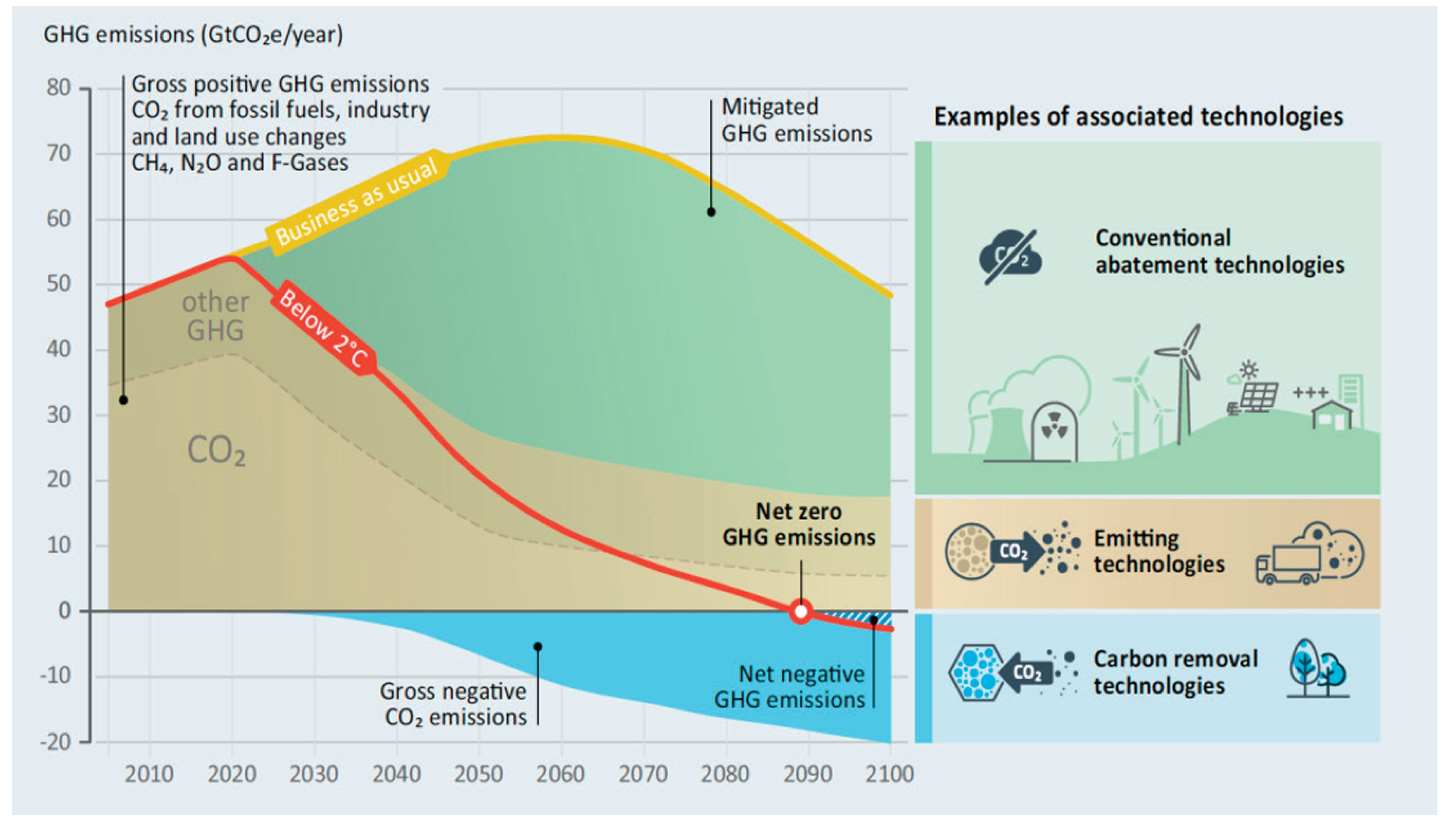
Figure 2.
Pipeline of Commercial facilities since 2010 by capture capacity (MTPY) (Global CCS Institute)
Figure 2.
Pipeline of Commercial facilities since 2010 by capture capacity (MTPY) (Global CCS Institute)
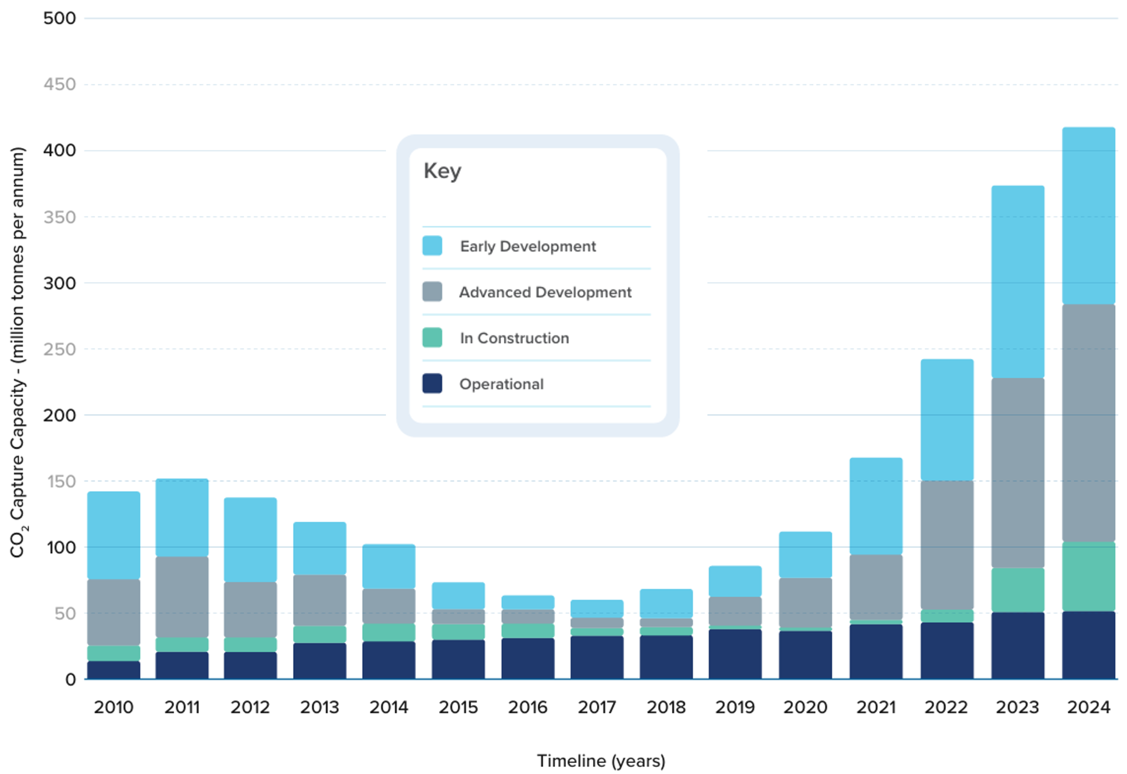
Figure 3.
IEA (2025, Status of CO2 storage infrastructure in development vs. planned capture capacity by region, 2025, IEA, Paris
Figure 3.
IEA (2025, Status of CO2 storage infrastructure in development vs. planned capture capacity by region, 2025, IEA, Paris
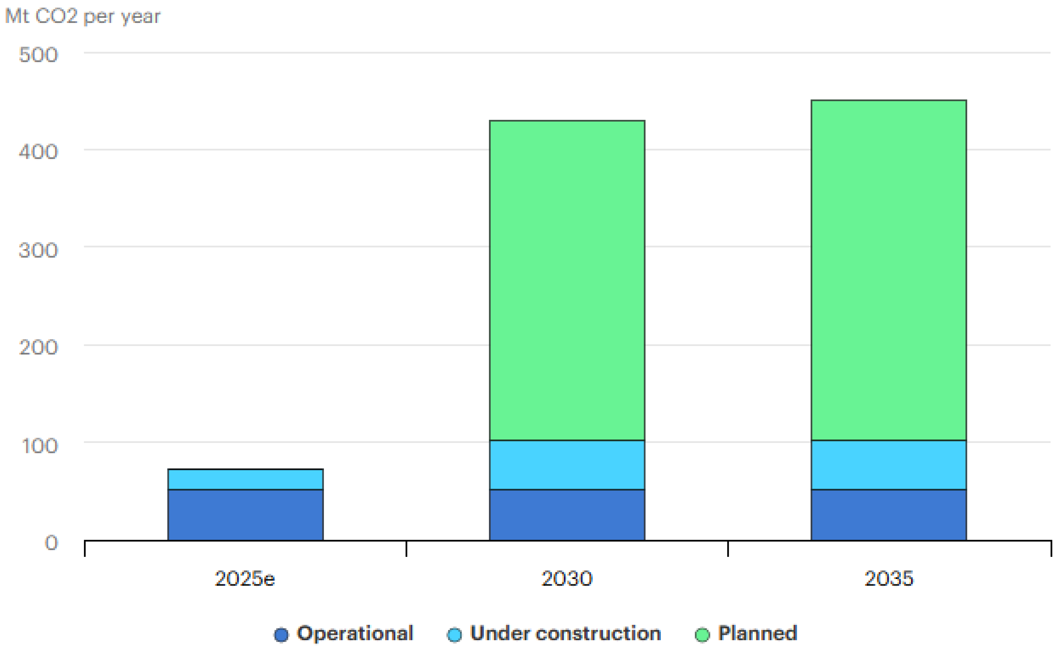
Figure 4.
Development of carbon capture technologies (Global CCS Inst. 2025)
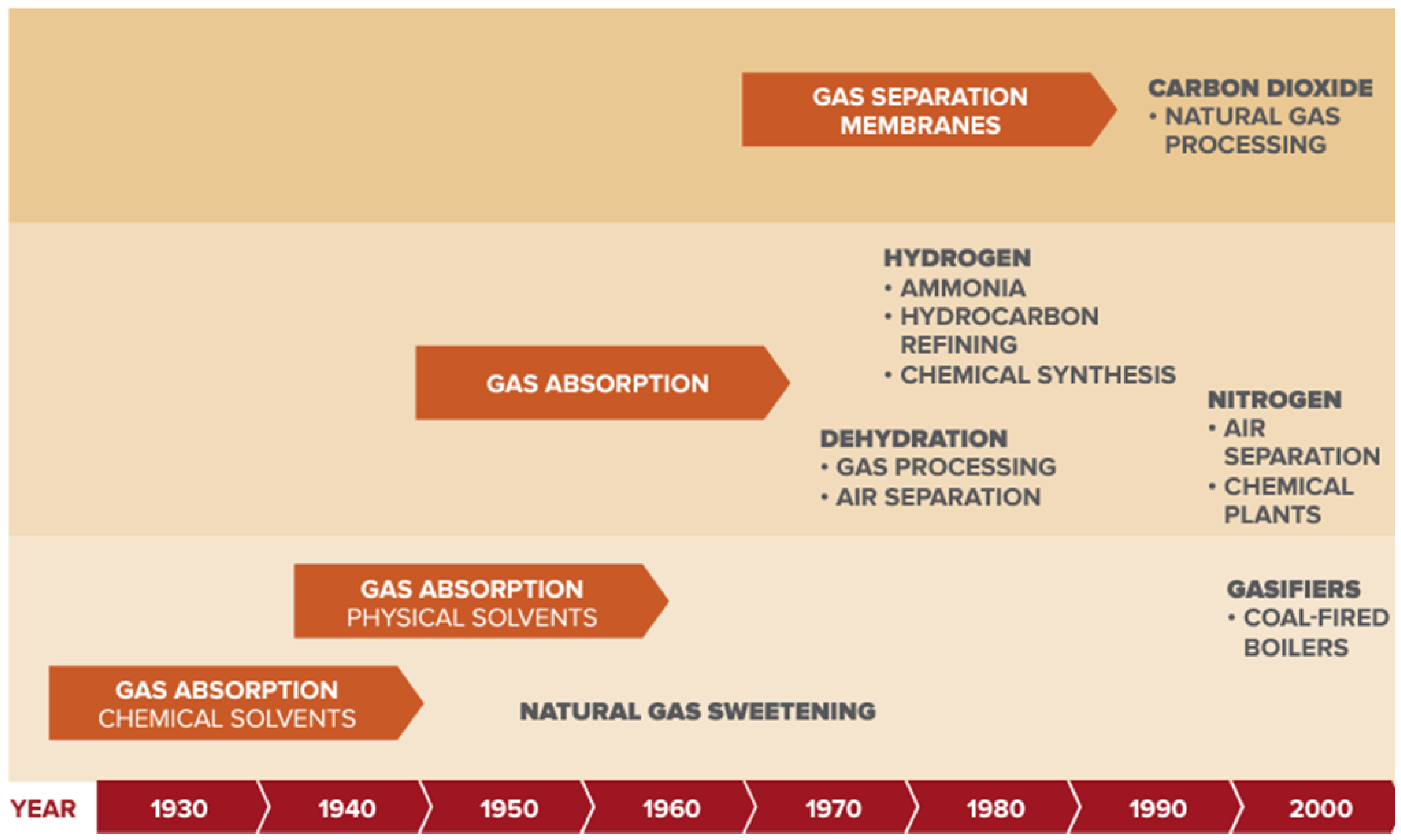
Figure 5.
Navigator Pipeline Plan (left, Navigator CO2, S&P Global) and Summit Carbon Solutions Plan (right,SCS).
Figure 5.
Navigator Pipeline Plan (left, Navigator CO2, S&P Global) and Summit Carbon Solutions Plan (right,SCS).
Disclaimer/Publisher’s Note: The statements, opinions and data contained in all publications are solely those of the individual author(s) and contributor(s) and not of MDPI and/or the editor(s). MDPI and/or the editor(s) disclaim responsibility for any injury to people or property resulting from any ideas, methods, instructions or products referred to in the content. |
© 2025 by the author. Licensee MDPI, Basel, Switzerland. This article is an open access article distributed under the terms and conditions of the Creative Commons Attribution (CC BY) license (https://creativecommons.org/licenses/by/4.0/).
Copyright: This open access article is published under a Creative Commons CC BY 4.0 license, which permit the free download, distribution, and reuse, provided that the author and preprint are cited in any reuse.


