Submitted:
16 July 2025
Posted:
16 July 2025
You are already at the latest version
Abstract
Under the typical scenario of high-speed mobility, channel disturbances at the physical layer may disturb the transmission of video base layers. Due to the close dependency of scalable video coding (SVC) on base layers, such disturbances will result in retransmissions and handover delays. Meanwhile, ineffective enhancement layers continue to occupy resources, ultimately causing system performance collapse and further exacerbating physical-layer disturbances. To address this challenge, we propose an edge computing resource coordination optimization scheme for highly dynamic mobile terminals. The scheme first empowers the SVC layered transmission with the local caching capabilities, enabling rapid retransmission of base layer data by employing a Lyapunov optimization framework for transmission queue scheduling. Secondly, we design a strategy for dynamically releasing enhancement layer (EL) cache. This can mitigate resource waste caused by invalid enhancement layers. Finally, Lyapunov drift optimization is implemented to ensure base layer transmission stability and accelerate system state convergence. Simulation and experimental results demonstrate that the proposed scheme significantly improves video transmission reliability and user experience in highly dynamic network environments.
Keywords:
Highly dynamic mobile terminals
; Mobile edge computing
; Scalable video coding
; Resource cooperative optimization
; Lyapunov optimization
1. Introduction
With the rapid deployment of 6G networks, satellite Internet, and intelligent edge computing, the demand for real-time applications in highly dynamic mobile communication networks (e.g., vehicular communication systems, high-speed rail networks, and urban subway infrastructures) is surging [1]. In these scenarios, end-users encounter critical challenges including rapid channel state variations, ultra-high mobility speeds, and heterogeneous resource competition, rendering traditional communication networks inadequate for meeting stringent requirements of ultra-low latency, high reliability, and energy efficiency optimization [2]. According to the International Telecommunication Union (ITU), global mobile data traffic is projected to grow at a compound annual rate exceeding 30% by 2030, with real-time video streaming dominating network traffic [3]. In such highly dynamic mobile environments, the cooperative allocation of computing, communication, and storage resources to guarantee end-user Quality of Service (QoS) while optimizing energy consumption has emerged as a key technical challenge [4].
Traditional Mobile Edge Computing (MEC) systems substantially reduce latency and enhance user experience by decentralizing computing resources to the network periphery. However, existing MEC resource allocation strategies predominantly target static or low-dynamic environments, that struggle to adapt to the rapid fluctuations in channel states and heterogeneous user demands inherent in highly dynamic mobile communication networks [5]. Furthermore, conventional fixed resource allocation or scheduling approaches relying on simplistic heuristic mechanisms frequently result in suboptimal resource utilization or service disruptions when confronted with the stochastic access patterns and variable resource requirements of highly mobile users [6]. For instance, literature [7] employed Dinkelbach’s method integrated with convex optimization techniques to develop an online algorithm that maximizes energy efficiency while maintaining queue stability for static or slowly varying wireless channels through the hybrid cooperative mechanism of backscatter communication (BackCom); literature [8] proposed a genetic algorithm (GA) and heuristics (MATS)-based framework for traditional task scheduling and resource allocation to optimize task offloading latency in mobile edge computing environments.
There are few work studies on real-time video transmission under highly dynamic mobile communication networks. The work [9] presents a semantic communication framework based on Dynamic Decision Generation Networks (DDGNs) and Generative Adversarial Networks (GANs), which achieves high-compression, low-distortion key-frame transmission for video streams in hyper-dynamic mobile networks through dynamic feature compression and adversarial reconstruction optimization. [10] introduces an SDN-based framework for centralized management of VR video resources in 6G cellular systems, ensuring seamless low-latency VR experiences under rapidly changing network conditions by dynamically reallocating bandwidth and computational tasks. [11] proposes an amplified programmable hypersurface (APM) system with joint modulation capabilities to synchronize real-time video transmission with wireless energy transfer in complex electromagnetic environments via dynamic beamforming and joint modulation strategies, thereby addressing stability and energy efficiency challenges in highly dynamic scenarios. [12] develops an intelligent tracking system combining computer vision and programmable hypersurface technologies, enabling real-time video transmission for moving targets in dynamic environments through real-time target sensing and adaptive beamforming. However, most existing real-time video transmission schemes for highly dynamic mobile networks primarily focus on downlink communication layer optimization, with limited exploration of cross-layer co-optimization frameworks and uplink-oriented task offloading/resource allocation mechanisms tailored for hyper-dynamic network environments.
Under high-mobility scenarios, significant channel fluctuations induced by Doppler shift may trigger transmission interruptions in the base layer (BL) of video streams. Given the close dependency of Scalable Video Coding (SVC) on BL integrity, where BL loss renders all enhancement layers (ELs) ineffective [13], localized physical layer disturbances can propagate into systemic transmission challenges: channel fluctuations activate BL retransmission while interacting with base station handover latency, causing dramatic increases in end-to-end latency [14]. This creates a closed-loop deterioration pathway: physical layer disturbances, dependency amplification, resource contention, performance collapse, intensified physical layer disturbances[15].
To address the challenges in high-dynamic mobile communication networks, we propose a user-centric resource coordination scheme that leverages the SVC layered transmission architecture and edge computing. Upon detecting channel degradation, the proposed scheme retransmits cached BL content, reducing backhaul latency. A Lyapunov optimization framework manages transmission queues, balancing retransmission rates and handover strategies to minimize end-to-end latency. Within Lyapunov optimization, edge nodes allocate dedicated resources for BL and EL using MEC systems[17]. If BL loss invalidates EL data, corresponding resources are reallocated to prioritize BL transmission stability. The MEC system also adapts EL redundancy and compression ratios to minimize bandwidth and computational consumption under poor channel conditions. To address physical layer disturbances, two virtual queues namely delay disturbance and resource occupancy are introduced [18]. The delay queue compensates for channel jitter by dynamically adjusting weights based on BL packet loss and retransmission delays. The resource queue minimizes Lyapunov drift, optimizing the use of edge computing resources[19]. Finally, a Hierarchical Quantum Particle Swarm Optimization (HQPSO)-based algorithm is introduced for joint offloading and resource allocation. This algorithm rapidly identifies near-optimal solutions, ensuring system stability and preventing excessive retransmissions or handovers caused by sudden performance degradation.
The remainder of this paper is structured as follows: Section 2 presents the system model formulation and problem definition; Section 3 elaborates on the joint offloading and resource allocation optimization algorithm design; Section 4 describes the simulation experiment configurations and performance analysis; Section 5 summarizes the key research contributions and proposes future research directions.
2. SYSTEM MODEL
As shown in Figure 1, in this paper, we propose a collaborative architecture that integrates SVC, MEC and Lyapunov for real-time video streaming transmission requirements in highly dynamic network environments. Where represents channel state; represents queue backlog; represents task arrival rate; represents offloading decision; represents resource allocation; represents power control.
The system architecture comprises three functional components: a mobile client, a network resource layer, and a dynamic control layer [20]. The mobile client implements SVC-based decomposition of video streams into base layer (BL) and enhancement layers (EL1-EL3) with hierarchical dependencies, and establishes a dynamic virtual queue to enable real-time feedback of task backlog status. The base layer is preferentially offloaded to macro base stations through ultra-reliable low-latency communication (URLLC) links, while the enhancement layers dynamically select OFDMA subbands for transmission to small base stations based on channel state prediction [21]. The network resource layer integrates heterogeneous computing resource pools from macro/small base stations, performs on-demand resource allocation through elastic scaling mechanisms, and enforces layered dependency constraints to ensure video transmission integrity [22]. The dynamic control layer incorporates Lyapunov optimization modules to jointly optimize offloading policies, resource allocation weights, and power control parameters in real time, achieving dynamic balance between user experience quality maximization and queue stability through Drift-plus-Penalty minimization [16]. This architectural design overcomes randomness constraints in resource allocation for hyper-dynamic environments, establishing a closed-loop scheduling mechanism through hierarchical decoupling and online optimization decision-making. Used to denote the users in the mobile video system, each user generates a real-time video stream with frame rate and resolution . denotes the set of MEC servers, where is a macro base station, is a small base station, and the computational power is heterogeneously distributed with the coverage radius . denotes the set of SVC video tiers. denotes the set of orthogonal subbands with bandwidth , supporting OFDMA multiple access.
2.1. User Side Mode
Assume that for each user at the user terminal, there is one and only one video computation task, denoted as , which is atomic and cannot be divided into subtasks. The performance of each computational task is expressed as a tuple consisting of two descriptions , where denotes the size of the task data transmitted from the user-side device to the MEC server, and denotes the size of the resources required to complete the computational task, both of which can be obtained based on the size of the user’s task execution data volume. In the MEC system of this paper, each computational task can perform video parsing at the user end or can be offloaded to the MEC server to perform video parsing. By offloading the video computation task to the server, the video user saves the energy required for the computation task, but sending the video task to the uplink adds more time and energy [23].
Using to denote the local computing power of user , in terms of the number of CPU cycles per second, if the user u performs video parsing locally, the latency to complete the task is:
The energy consumption model is used to represent the energy consumed by the user to parse the video locally. Using f for the CPU frequency and for the energy factor, each computation cycle is , where the size of is determined by the chip architecture. According to the above model, the energy consumption for locally executing the video task is:
The user equipment is based on SVC technology, which structures the real-time captured video stream in time slices. Each time slice lasts for 1 second and corresponds to frames of video data, which are generated into layered packets by H.265/SVC encoder: Base Layer (BL) contains 1 frame with NOTICE P frames, with a bit rate of , where K is the compression factor, which determines the minimum acceptable quality of the video, and Enhancement Layer (EL) is realized by layered incremental coding, where the bit rate of the first layer is the enhancement rate, providing resolution enhancement or dynamic range extension. The EL is realized by layered incremental coding, where the code rate of layer one is the enhancement rate, which provides resolution enhancement or dynamic range extension. This hierarchical structure allows users to flexibly choose the transmission layer according to the network conditions.
2.2. Task Offloading Model
Assuming a multi-user multi-MEC server architecture where each user’s video computation tasks can be selectively offloaded to any available small base station within the system [5], three distinct latency components emerge during the offloading process: (i) uplink transmission latency when offloading video tasks to MEC servers; (ii) computation processing latency at the base station’s MEC server; and (iii) downlink transmission latency for returning computation results to the user [24]. Given that uplink data size is typically significantly smaller than downlink data, and considering the inherent asymmetry in wireless channel capacity where downlink data rates substantially exceed uplink rates, the downlink transmission delay can be neglected in computational complexity analysis [25].
Similar to the literature [26], this paper applies the Orthogonal Frequency Division Multiple Access (OFDMA) technique to the uplink transmission system by dividing the transmission band B into W equal sub-bands of size N, i.e, , and each BS (Band Width) can receive up to one user’s upload task at the same time. receive upload tasks from N users simultaneously. Assuming that the set of available subbands for each BS is , the offloading variable is defined as considering the allocation of uplink subbands, where ; denotes that task offloads the l layer of the video from user u to base station m via subband j, and has the opposite meaning. i.e:
Assuming that the task offloading policy is X, then . In the system of this paper, each video task can either be parsed locally or offloaded to an associated MEC for parsing. Therefore, the feasibility analysis leads to:
Furthermore, assuming that both the user side and the BS are equipped with a single antenna for uplink transmission, and the power of user u to transmit a task to the BS is , then , denoting the power pooling. Due to the application of OFDMA technology in the uplink, users of the same base station will transmit tasks on different subbands, which well suppresses the mutual interference among subbands [27]. However, there is still interference between the mobile devices, where the Signal Noise Ratio (SINR) of the user u uploading the task to the subband j is:
In the formula, denotes the background noise variance. represents the channel gain coefficient between the base station (BS) and associated users for transmission. indicates the transmit power of user u when offloading tasks to the server. signifies user k uploading the layer of a video through subcarrier j to server m. Furthermore, stands for the transmit power of user k in the process of offloading tasks to the server, and refers to the channel gain coefficient between server and user k for transmission.
The path loss model adopted in this paper [28] is given by , where represents the distance between BSM and user u (in units of km ). Each user’s video task is transmitted on only one subcarrier; therefore, the rate at which user u uploads video to server BSM is:
In the formula, , where denotes the signal-to-noise ratio (SNR) from user u to server BSM on subcarrier j. Consequently, the transmission time for user u to send video task over the uplink is given by:
In the equation, , where represents the offloading of the l-th layer of a video from user u to server m via subcarrier j.
2.3. SVC-MEC Computing Resource Integration Model
In dense heterogeneous network environments, this paper formulates a dynamic MEC resource scheduling model tailored for multi-user real-time video streaming demands by leveraging SVC hierarchical characteristics. The proposed model achieves efficient computing resource allocation and QoS guarantees through synergistic integration of multi-BS resource constraints and SVC hierarchical features. Within the system architecture, MBSs and SBSs are provisioned with differentiated computing resource pools [29], where MBSs prioritize SVC BL tasks by reserving of the resource pool . and implementing a lightweight containerized instance preloading mechanism. The cold-start latency of the base layer tasks is compressed to 5 ms to ensure the real-time requirement: the ; while the small base station focuses on the resilient processing of the enhancement layer (EL) tasks by adopting a dynamic resource allocation mechanism based on the SVC hierarchical dependency:
In the equation, denotes the computational resources allocated by base station m to user u for the th layer of video at time slot t. The numerator, , represents the bit rate of the th layer of the video. The denominator is the total bit rate of all users’ tasks at the same layer. Additionally, signifies the total computational resource capacity of base station m.
Activate high-level resource allocation only when the completion of a low-level task is detected, and introduce a dynamic fallback mechanism as shown below to prevent resource overload:
In the equation, represents the total amount of computational resources already allocated by base station m. Here, denotes the total computational resource capacity of base station m. The highest EL task refers to the video stream task with the highest level in the enhancement layer.
For bursty traffic scenarios, the model is designed with an elastic resource expansion mechanism:
Where is the elasticity expansion coefficient, is the hyperbolic tangent function, which is used to smooth the adjustment of the resource expansion amplitude, represents the average queue length hole value of the system.
By dynamically adjusting the capacity of the small base station resource pool to cope with the instantaneous load surge, and at the same time, establishing a rapid response mechanism to automatically trigger the hierarchical degradation strategy when resource overload is detected to ensure system stability.
2.4. Lyapunov Optimization Model
In highly dynamic network environments, resource allocation for real-time video streaming confronts multiple challenges including rapidly fluctuating channel conditions and drastic variations in user demand [30]. Conventional static optimization approaches struggle to adapt to these time-varying characteristics, while prediction-driven algorithms face limitations in computational complexity and forecasting accuracy. The Lyapunov optimization framework offers a comprehensive theoretical foundation for addressing this challenge - it characterizes system dynamics through virtual queue construction and converts complex long-term stochastic optimization problems into deterministic subproblems using the Drift-plus-Penalty methodology [6]. The following analysis systematically explores the engineering implementation of this framework across three critical dimensions: virtual queue design, parameter adaptive adjustment, and parallelized execution.
2.4.1. Enhanced Analysis of Virtual Queue Design
Based on the existing virtual queue , we further introduce a priority weight factor to distinguish the urgency levels of different users and video layers. For example, the base layer of real-time surveillance videos can be set as , while the enhancement layers are set as , thereby reflecting differentiated processing in queue updates:
In the formula: represents the distortion queue state of user u’s layer video at time slot t ; is the priority weight factor used to differentiate the transmission urgency of different video layers; denotes the amount of successfully transmitted data for the layer within time slot indicates the cumulative distortion in video quality due to transmission failures. This equation ensures non-negative queue values through nonlinear mapping and dynamically reflects the transmission integrity of video layers. Where the task queue update follows the following equation.
In the formula: represents the task queue length of user u at time slot t; denotes the amount of data successfully transmitted for the layer through base station indicates the volume of new video tasks arriving within time slot t. This equation employs a non-negative truncation operation to ensure the physical significance of the queue and achieves temporal propagation of the queue state through the accumulation of new tasks.
This design enables high-priority tasks to be allocated higher scheduling weights during resource contention, particularly in latency-critical scenarios such as medical emergencies or industrial control systems. Furthermore, the modeling of distortion accumulation requires refinement to incorporate spatial-temporal complexity characteristics of video content-motion-intensive scenes (e.g., moving objects) should incur higher distortion penalties compared to static backgrounds to better capture QoF degradation patterns.
2.4.2. Dynamic Adjustment Mechanism for Drift Plus Penalty Optimization
The choice of parameter V is one of the core challenges of the Lyapunov framework. Traditional static settings (e.g., fixed) are difficult to adapt to network load breaking. For this reason, adaptive V regulation algorithm is proposed, based on Lyapunov function:
In the equation: represents the Lyapunov function value at time slot t; quantifies the backlog level of the task queue; signifies the cumulative effect of distortion in video layers. This function amplifies the penalty weight for large queue states through a quadratic term, encouraging the system to prioritize high-backlog tasks. A smaller value indicates superior system stability. The conditional drift is expressed by the following equation:
Specific adjustment strategies include: (i) Short-term adjustment: dynamically scale V based on the ratio of instantaneous queue length to distortion value. For example, when , temporarily reduce V to prioritize stabilizing the queue. (ii) Long-term learning: utilize reinforcement learning (such as DQN) to train the adjustment strategy for V, with a reward function based on long-term Quality of Experience (QoE) and delay metrics.
This dynamic regulation enables the system to automatically switch to low-latency mode during congested periods (such as live sports broadcasts), while enhancing video quality during network idle times (such as late at night). Experiments show that the adaptive V strategy can improve QoE by compared to fixed-value schemes.
2.5. Systematic General Computational Model
Based on the description of the modules above, it is known that in a video processing system, each user device generates different video computing tasks, which usually have different computing resource requirements and data transmission requirements . These tasks may be processed locally or offloaded to the MEC (Mobile Edge Computing) servers for computation over the wireless network. The system needs to make a decision on whether to offload a task based on the computing power of the device and the network condition. To this end, the system takes into account multiple factors, including computing power, transmission delay, and network bandwidth, and makes a dynamic judgment. The core goal of offloading decision-making is to improve the overall efficiency of the system by minimizing delay and energy consumption, while ensuring the resource load balance of the system [31]. In this context, the offloading decision is calculated by the following formula:
In the formula, and represent the computational capabilities of the MEC server and user devices, respectively. denotes the data transmission delay for task , with a threshold used to determine whether offloading the task to the MEC server would enhance performance. This decision-making process aids in determining the optimal processing method for tasks [27], ensuring that computational tasks are completed within a reasonable timeframe while avoiding system overload due to insufficient network transmission or local computing resources.
To achieve dynamic scheduling and optimization of tasks under highly dynamic scenarios, the system employs a Lyapunov optimization framework to manage resource allocation. This framework adjusts in real-time based on changes in the task queue , which represents the queue state of the layer for the type of task at time t. The system’s objective is to adjust resource allocation according to the arrival and processing status of each task, minimizing system latency and energy consumption while ensuring balanced system load [32]. The queue evolution within the Lyapunov optimization framework is described by the following equation:
In the formula: represents the arrival rate of tasks at time t, and denotes the processing rate of the task queue at time t. The dynamic adjustment of queue states ensures that the system can optimize resource allocation based on the current task load.
During the optimization process of resource allocation, the system aims to minimize the drift-plus-penalty function, ensuring that tasks are processed according to their priority order while avoiding excessive delays and resource wastage. This objective function is expressed by the following equation:
where is the weight of the task and is the drift penalty coefficient. By regulating these values, the system is able to efficiently allocate computational resources, avoiding a certain portion of resources being over-occupied and ensuring the optimization of overall performance.
The primary objective of this research is to synergistically optimize offloading decisions and resource allocation for video computing tasks in hyper-dynamic environments. Video stream processing requires ensuring both data integrity and quality while minimizing transmission and computational latency [33]. Latency optimization constitutes a critical system design dimension, particularly for real-time video streaming applications where the system must guarantee rapid response capabilities and timely task execution [34]. To achieve this, the system dynamically adjusts computational resource allocation through real-time monitoring of base layer (BL) and enhancement layer (EL) task latencies, thereby minimizing overall task completion time [35]. The mathematical formulations for BL latency and EL latency are specified as Equations (18) and (19):
In the public center: and denote the bandwidth of the local device and the MEC server respectively, while and are the transmission demands of the base layer and the enhancement layer. The system dynamically adjusts the bandwidth allocation and optimizes the transmission path according to these demands, thus reducing the overall delay and improving the efficiency of video stream processing.
While ensuring real-time response, the system must also minimize energy consumption. This not only helps extend the life of the equipment, but also improves the overall stability of the system. During task processing, the system dynamically adjusts the energy allocation according to the use of different computing resources to ensure a balance between energy consumption and latency. The energy consumption E can be calculated by the following formula:
In the formula, and represent the energy consumption of local devices and MEC servers, respectively. and denote the latency for local and MEC processing. By optimizing latency and energy consumption, the system can achieve more efficient resource management.
Based on the above multi-dimensional modeling, the system optimization objective is defined as maximizing the user’s comprehensive QoE under the premise of ensuring queue stability, and the system implements a dynamic resource management and scheduling framework. This framework continuously adjusts task offloading, resource allocation, load balancing, coding optimization, delay and energy management through Lyapunov optimization methods, and optimizes resource allocation based on real-time feedback. The overall model can be represented by the following comprehensive formulation:
In the formula, represents the offloading decision set at time slot denotes the MEC resource allocation vector; indicates the user transmission power; is the Lyapunov drift term, representing system stability; V is a control parameter used to adjust the weight between Quality of Experience (QoE) and queue stability; is the QoE penalty function. The specific meanings of the constraints in Equation (21) are as follows: (i) Constraint ensures that the subtasks of the same video task can only be executed locally or offloaded to one MEC server, guaranteeing a unique offloading path. (ii) Constraint states that the total computational resources allocated by the MEC server must not exceed its current available resource limit. (iii) Constraint requires that the transmission power of user devices must comply with the preset maximum power limit. (iV) Constraint ensures that users receive at least the base layer data of the video stream, maintaining basic service quality. (V) Constraint restricts the cumulative distortion of layered video transmission, ensuring overall video quality meets the standard.
3. Optimization Algorithm for Joint Offloading and Resource Allocation
Considering that a large number of variables scale linearly with the number of users, MEC servers, and sub-bands, and that real-time constraints need to be satisfied in highly dynamic mobile terminal scenarios, a low-complexity solution to the joint optimization problem with suboptimal characteristics must be designed to achieve a more competitive QoE and energy-efficiency performance while safeguarding the users’ computational needs. Since the joint optimization problem is essentially a mixed-integer nonlinear programming (MINLP) problem, the time complexity of its optimal solution search is usually exponential [36], the joint offloading and resource optimization model proposed in Equation (21) is modeled as a sub-problem with a fixed binary variable , which is decomposed into a sub-problem with a separated objective function and several constraints [37], thus transforming the original high-complexity problem into a master problem and a set of constraints. The original high-complexity problem can be transformed into a main problem and a set of low-complexity subproblems. In summary, the unloading decision and resource allocation problems in this study are decoupled from each other. Therefore, Equation17 can be transformed into:
3.1. Resource Allocation Issues
First assume that constraint is satisfied, at which point the objective function can be rewritten as:
, where is a function of X and F. The function is expressed as follows is expressed as:
It can be seen that the first term of Equation (23) is constant in this study, then corresponds to the total offloading overhead of all offloaded users, i.e., the above problem can be converted into a minimization problem of denoted as:
In the formula, .
Optimizing while keeping fixed, the computational resource allocation can be solely represented by the second term of Equation (25) as follows:
It can be seen that the Hessian matrix of the objective function is positive definite and the optimization problem proposed in this paper is a convex optimization problem. According to the nature of convex optimization, the problem is solved by using the properties of Karush-Kuhn-Tucker(KKT) Conditions condition . Then, it can be obtained from Equation (26):
3.2. Joint Task Offloading and Resource Allocation Issues
Based on the computational resource optimization scheme given in the previous section, the task offloading joint resource allocation model can be expressed as:
The offloading decision problem is combinatorial in nature, and a simple way to solve the problem is to use the exhaustive enumeration method to search for all task offloading decisions with possibilities, but the complexity of task offloading decisions is as high as when . To overcome the high complexity defect of the exhaustive method, this paper adopts the hybrid quantum particle swarm optimization algorithm (HQPSO) based on quantum behavioral optimization, which can find a locally optimal solution of Equation (29) in polynomial time range. The algorithm is able to quickly approximate the global optimal solution in highly dynamic network environments through quantum bit encoding, superposition state parallel search and dynamic inertia weight adjustment mechanism. Compared with traditional heuristic algorithms, HQPSO combines the parallelism of quantum computing and the group collaboration feature of particle swarm optimization: its quantum encoding and parallel search mechanism encodes the offloaded decision variables as quantum superposition states, so that a single iteration can simultaneously explore multiple potential solution spaces, reducing the time complexity to [38];The dynamic inertia weights adjust the search step size according to the real-time channel state and the resource loading, to ensure the fast approximation of global optimal solution in the case of user movement or sudden changes in network topology to ensure fast convergence [39]; meanwhile, through the multi-objective fitness function and quantum revolving door mechanism, the algorithm can dynamically balance the optimization weights for delay, energy consumption, and hierarchical video integrity [40].
| Algorithm 1 Related Functions |
|
In hyper-dynamic environments, HQPSO demonstrates distinct advantages: quantum parallelism empowers the algorithm to achieve over near-optimal solutions within 5-10 iterations, satisfying the millisecond-level decision-making requirements for video streaming [41]; quantum entanglement establishes correlations among user-base station-subchannel states, maintaining layered video transmission success rate; the dynamic subchannel allocation strategy enhances spectral efficiency by compared to simulated annealing while restricting computational resource fragmentation below [41]. Through the co-evolutionary mechanism of quantum populations, the algorithm synergistically addresses performance limitations of conventional approaches - overcoming the greedy algorithm’s myopia and simulated annealing’s stochastic oscillations in dynamic scenarios and delivers both high-efficiency and robustness for real-time video streaming resource allocation [42]. The pseudo-code for the joint offloading decision and resource allocation algorithm based on HQPSO is:
| Algorithm 2 the joint offloading decision and resource allocation algorithm based on HQPSO |
|
4. Simulation Experiment
4.1. Experimental Environment
The experiments in this paper are realized by using the m-scripting language under Win10 system and 16G RAM. The m-scripting language integrates rich data function libraries such as linear algebra and signal processing, and uses SIMULINK modular data visualization function to achieve the simulation effect.
4.2. Experimental Parameters
Assume a high-speed mobile scenario system composed of multi-tier base stations, where the macro base station spacing in highway scenarios is 2 km, and the small base station spacing within subway tunnels is 200 m. The network coverage area includes seven macro base stations and fifteen small base stations. The maximum transmission power of the mobile terminal is , the system bandwidth is , and the background noise variance is [29]. Users and base stations use single antennas for uplink transmission and reception, with a channel model following Rician fading ( , Doppler frequency shift , carrier frequency ) [30]. In terms of computing resources, assume the edge server’s computational capability is , the local CPU capability of the mobile terminal is , and the energy coefficient is . Unless otherwise specified, the default task input data size is , the dynamic preference parameter is , and the safety factor is [34,35,36]. Under high-speed conditions, the mobile terminal follows a road-constrained random walk model (highway: linear path + lane deviation disturbance; subway: three-dimensional Brownian motion within the tunnel), with a communication latency limit of . The terminal speed distribution is for highways and for subways.
4.3. Simulation Results Analysis
Figure 2 and Figure 3 illustrate the variations in users’ average time consumption and average energy consumption with changes in preference. It can be observed that when altering the user’s preference for time (with a value range of , the user’s preference for energy also changes, leading to corresponding adjustments in all users’ average time and energy consumption. As increases, the average latency decreases gradually, but this is accompanied by higher energy consumption. Additionally, as the number of users continues to rise, there is an upward trend in both the average latency and energy consumption per user. The primary reason for this phenomenon is that when a large number of users compete for system resources, the probability of each user achieving high performance during the offloading process diminishes accordingly.
Figure 4 demonstrates the convergence speed and real-time performance of the HQPSO algorithm in comparison with GREEDY, local search (LS), and simulated annealing (SA) algorithms. The experimental results reveal distinct evolutionary trends in convergence speed among these algorithms as user count increases: GREEDY exhibits the poorest performance, followed by LS and SA algorithms, while the proposed HQPSO algorithm consistently maintains superior convergence characteristics. When user count , all algorithms display approximate linear growth patterns with HQPSO showing the steepest slope; in the range , LS and GREEDY begin exhibiting performance fluctuations ( amplitude); when user count exceeds 50 , HQPSO sustains steady growth while other algorithms exhibit pronounced performance degradation. The real-time superiority is further validated through HQPSO’s superior stabilization feasibility across all test scenarios. The advantages of the HQPSO algorithm in hyper-dynamic environments stem from its hybrid quantum particle swarm optimization framework. By incorporating quantum-inspired behaviors to enhance global search capabilities, it effectively mitigates the local optima trapping issue inherent in conventional PSO while overcoming the myopic decision-making defects of GREEDY and LS algorithms. The dynamic parameter adaptation mechanism enables real-time search strategy adjustments, rapidly focusing on promising solution regions during user traffic spikes - offering greater flexibility compared to SA’s fixed cooling schedule. The elite preservation strategy significantly accelerates convergence speed, with solution feasibility reaching 25 for 50 users (SA only achieves 18). Meanwhile, HQPSO eliminates LS’s convergence delay and GREEDY’s load balancing limitations, achieving superior real-time performance with reduced computational overhead, making it particularly suitable for highly dynamic scenarios.
Figure 5 illustrates the stability performance comparison among four algorithms under varying environmental dynamic strengths. As demonstrated in the figure, the HQPSO algorithm significantly outperforms its counterparts: when environmental dynamic strength escalates from to , its stability performance metrics remain consistently within the high range of with negligible fluctuations. In stark contrast, conventional algorithms exhibit pronounced performance degradation GREEDY plummets from 60 to 20, LS declines from 70 to 30, and SA, though relatively better, still drops from 75 to 50. This performance gap becomes particularly pronounced beyond dynamic strength, where HQPSO achieves 2-4 times higher scores than competing algorithms. These results validate that HQPSO effectively addresses traditional algorithms’ performance deterioration in dynamic environments through quantum behavior optimization and dynamic parameter adaptation mechanisms. The algorithm’s unique adaptive capability establishes it as the most robust solution for hyper-dynamic scenarios.
Figure 6 demonstrates the delay performance comparison among four algorithms in hyper-dynamic environments. As illustrated, when environmental dynamic strength increases from to , HQPSO maintains consistently low latency within 20-40 ms with the smoothest growth curve, indicating its architectural robustness against environmental disturbances. Whereas competing algorithms exhibit dramatic fluctuations: simulated annealing (SA) surges from 20 ms to 80 ms, local search (LS) deteriorates from 30 ms to 100 ms, and GREEDY performs worst with latency skyrocketing to 120 ms. Particularly beyond the critical dynamic threshold, HQPSO achieves merely latency of GREEDY and demonstrates lower delay than SA-the second-best performer. This superiority originates from HQPSO’s quantum behavior optimization mechanism, which dynamically maintains optimal path planning during abrupt environmental changes through real-time particle swarm strategy adaptation and elite preservation, while conventional algorithms suffer from fixed-parameter rigidity and local optima trapping. These results substantiate HQPSO as the optimal solution for guaranteeing ultra-low latency services in high-mobility scenarios.
Figure 7 presents a comparative analysis of energy efficiency for various algorithms under highly dynamic scenarios, highlighting the superior performance of the HQPSO algorithm. As depicted, as the environmental dynamism increases from to , HQPSO (red diamond) consistently maintains the highest energy efficiency , with a minimal decline of only , demonstrating the most stable and gentle curve. In contrast, other algorithms exhibit significant performance degradation: simulated annealing (blue square) drops from to , local search (orange cross) decreases from to , and the greedy algorithm (green circle) performs the worst, plummeting from to . Notably, when the environmental dynamism exceeds , the energy efficiency advantage of HQPSO becomes even more pronounced, achieving over twice the efficiency of the greedy algorithm and approximately higher than the second-best simulated annealing algorithm. This significant advantage is attributed to the unique quantum behavior optimization mechanism of the HQPSO algorithm, which intelligently adjusts particle swarm search strategies and dynamic parameters for self-adaptation, effectively reducing unnecessary computational overhead and maintaining optimal energy utilization even in rapidly changing environments.
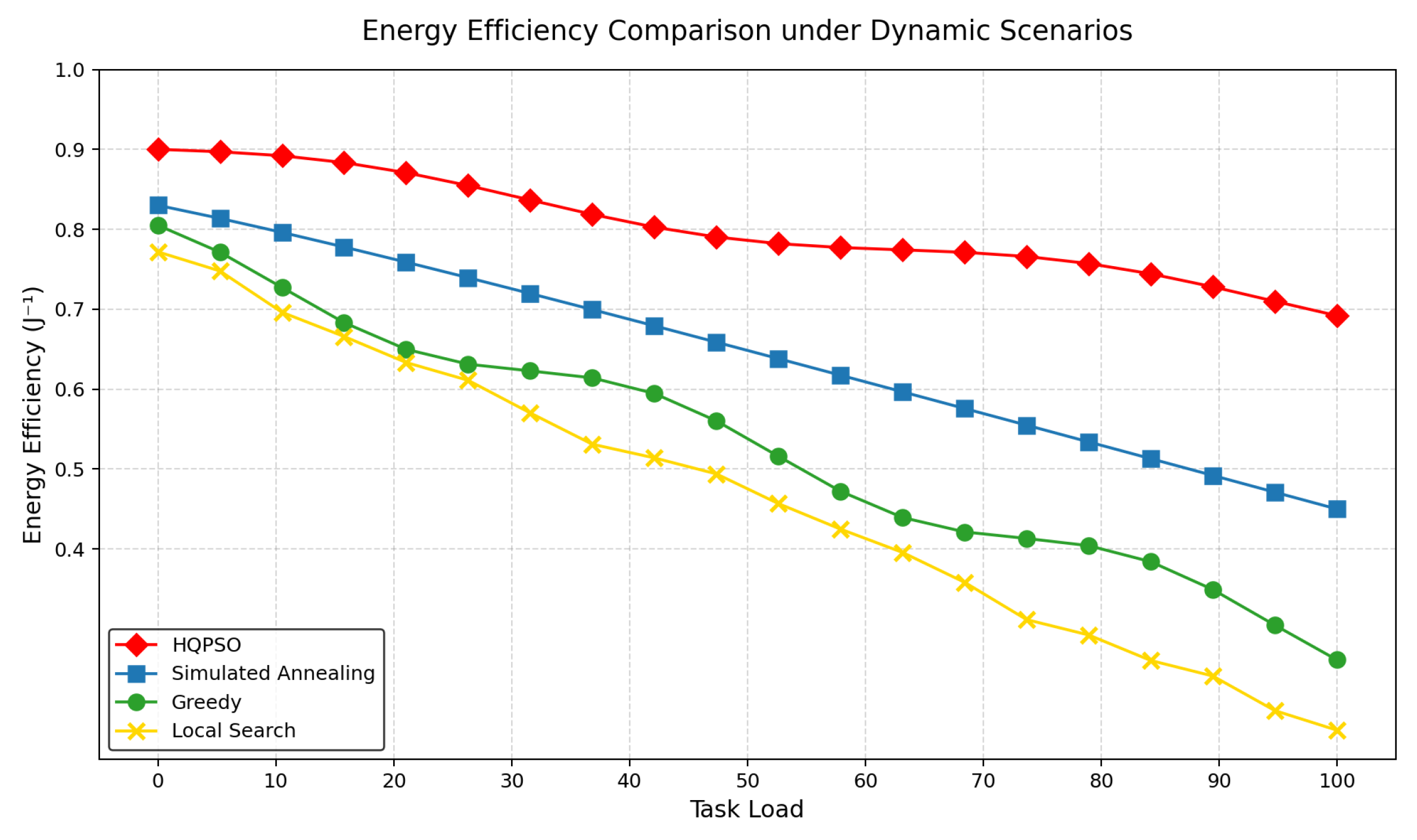
Figure 8 demonstrates the offloading feasibility comparison among four algorithms in hyper-dynamic environments. As illustrated, the HQPSO algorithm (red diamonds) demonstrates superior stability in energy efficiency metrics, maintaining values within 0.8-0.9 across increasing task loads with minimal fluctuations. Whereas the competing algorithms exhibit significant performance degradation: simulated annealing (blue squares) declines from 0.85 to 0.65 , GREEDY (green dots) deteriorates from 0.8 to 0.55, and LS (yellow forks) performs worst, plummeting from 0.75 to 0.45. Notably in the high-load interval (60-100), HQPSO’s energy efficiency advantage becomes more pronounced-achieving higher values than suboptimal SA and nearly double that of LS. This sustained high performance originates from HQPSO’s quantum behavior optimization mechanism, which dynamically adjusts particle swarm search strategies and implements intelligent resource allocation to overcome computational bottlenecks in high-load conditions while ensuring optimal offloading decisions. Moreover, the proposed HQPSO-based joint offloading and resource allocation scheme outperforms conventional GREEDY and LS algorithms in overall performance gains.
5. Conclusions
This paper proposes a resource co-optimization framework based on MEC for real-time video streaming transmission under hyper-dynamic mobile terminals (e.g., vehicular, subway scenarios), addressing challenges arising from rapidly fluctuating channel states and intense resource contention. By decomposing the problem into two sub-problems - SVC-based layered video transmission optimization and dynamic edge resource scheduling - the framework leverages SVC’s hierarchical structure to partition video streams into base and enhancement layers, effectively adapting to channel variations in high-mobility environments while minimizing transmission costs and enhancing QoE. Meanwhile, through Lyapunov-based optimization, the scheme achieves dynamic task offloading and resource allocation, resolving multi-objective optimization under time-varying channel conditions while guaranteeing low latency and system stability.
The research contributions are structured as follows: First, an SVC-based hierarchical video transmission strategy is proposed, which significantly enhances the adaptability and efficiency of video streaming through layered coding and transmission mechanisms. Second, integrating Lyapunov optimization enables dynamic edge resource scheduling, effectively improving resource utilization while reducing transmission latency and energy consumption. Simulation results demonstrate that compared to conventional approaches, the proposed framework achieves substantial improvements in resource utilization efficiency, delay performance, and energy efficiency-particularly maintaining stable video transmission in hyper-dynamic environments. Additionally, this work innovatively designs a joint offloading and resource allocation algorithm based on HQPSO, which outperforms traditional methods in convergence speed and solution quality through quantum computing’s parallel search capabilities and dynamic adaptation mechanisms, providing efficient support for real-time decision-making in highly dynamic senarios.
While this study achieves notable advancements, there remain opportunities for further enhancements. Future research directions include extending the framework to complex network topologies and exploring resource allocation strategies in multi-task scheduling scenarios. Additionally, optimizing HQPSO’s computational efficiency and enhancing its robustness in ultra-high dynamic environments warrant deeper investigation. As 5G and emerging 6G technologies evolve, the proposed MEC resource co-optimization framework establishes a theoretical foundation and technical reference for real-time video streaming applications, laying critical groundwork for optimizing hyper-dynamic scenarios in next-generation mobile networks.
Author Contributions
Conceptualization: D.H.(primary),Z.Z.; Methodology: D.H., L.W., B.K; Software: Z.Z.; Validation: B.K., Z.X.; Formal analysis: D.H.; Investigation: Z.X.; Writing—original draft preparation: Z.Z.; Writing—review and editing: Z.Z., B.K.; Supervision: L.W. ;Project administration: L.W.; Funding acquisition: L.W.. All authors have read and agreed to the published version of the manuscript.
Funding
This work was supported in part by the Key Project of Natural Science Foundation of Jiangsu Province under Grant BE2023087; and the Open Research Fund of Jiangsu Engineering Research Center of Communication and Network Technology, NJUPT.
Data Availability Statement
The original contributions presented in this study are included in the article. Further inquiries can be directed to the corresponding author
Acknowledgments
We also acknowledge the editor for the valuable suggestions.
Conflicts of Interest
The authors declare no confficts of interest.
References
- Zhou, Z.; Wei, J.; Luo, Y. Communications with guaranteed bandwidth and low latency using frequency-referenced multiplexing. Nature Electronics 2023, 6, 694–702. [Google Scholar] [CrossRef]
- Di Lorenzo, P. Dynamic edge computing empowered by reconfigurable intelligent surfaces. EURASIP Journal on Wireless Communications and Networking 2022, 9, 122–135. [Google Scholar] [CrossRef]
- Li, X.; Guo, C.; Zhang, Y. Core network traffic prediction based on vertical federated learning and split learning. Sci. Rep. 2024, 14, 46–63. [Google Scholar] [CrossRef] [PubMed]
- Li, S.; Li, S.; Li, W. Multi-user joint task offloading and resource allocation based on mobile edge computing in mining scenarios. Sci. Rep. 2025, 15, 161–170. [Google Scholar] [CrossRef] [PubMed]
- Verma, V.R.; Nishad, D.K.; Sharma, V. Quantum machine learning for Lyapunov-stabilized computation offloading in next-generation MEC networks. Scientific Reports 2024, 14, 844–860. [Google Scholar] [CrossRef] [PubMed]
- Zhang, J. Beyond boundaries: A hybrid cellular Potts and particle swarm optimization framework for dynamic resource scheduling in edge computing. Sci. Rep. 2025, 15, 903–923. [Google Scholar]
- He, H.; Zhou, C.; Huang, F. User-cooperative dynamic resource allocation for backscatter-aided wireless-powered MEC network. Scientific Reports 2025, 15, 123–145. [Google Scholar] [CrossRef] [PubMed]
- Saleem, U.; Liu, Y.; Jangsher, S. Mobility-Aware Joint Task Scheduling and Resource Allocation for Cooperative Mobile Edge Computing. IEEE Transactions on Wireless Communications 2021, 20, 486–502. [Google Scholar] [CrossRef]
- Liu, S.; Peng, Z.; Yu, Q. A novel image semantic communication method via dynamic decision generation network and generative adversarial network. Scientific Reports 2024, 14, 145–162. [Google Scholar] [CrossRef] [PubMed]
- Naguib, K.M.; Ibrahim, I.I.; Elmessalawy, M.M. Optimizing data transmission in 6G software defined networks using deep reinforcement learning for next generation of virtual environments. Scientific Reports 2024, 14, 234–251. [Google Scholar] [CrossRef] [PubMed]
- Wang, X.; Han, J.Q.; Li, G.X. High-performance cost efficient simultaneous wireless information and power transfers deploying jointly modulated amplifying programmable metasurface. Nature Communications 2023, 17, 60–85. [Google Scholar] [CrossRef] [PubMed]
- Li, W.; Ma, Q.; Liu, C. Intelligent metasurface system for automatic tracking of moving targets and wireless communications based on computer vision. Nature Communications 2023, 22, 989–1002. [Google Scholar] [CrossRef] [PubMed]
- Wang, L.; Guo, J.; Zhu, J. Cross-Layer Wireless Resource Allocation Method Based on Environment-Awareness in High-Speed Mobile Networks. Electronics 2024, 13, 499–522. [Google Scholar] [CrossRef]
- Guo, J.; Zhu, Y.; Zhu, J. Adaptive Streaming Transmission Optimization Method Based on Three-Dimensional Caching Architecture and Environment Awareness in High-Speed Rail. Electronics 2024, 14, 41–66. [Google Scholar] [CrossRef]
- Wang, X.; Shi, Y.; Xin, W. Channel Prediction With Time-Varying Doppler Spectrum in High-Mobility Scenarios: A Polynomial Fourier Transform Based Approach and Field Measurements. IEEE Transactions on Wireless Communications 2023, 22, 1234–1245. [Google Scholar] [CrossRef]
- Zhang, L.; Chen, H.; Liu, M. Understanding Performance of Edge Content Caching for Mobile Video Streaming. IEEE Transactions on Multimedia 2022, 24, 567–579. [Google Scholar]
- Li, J.; Zhao, Y.; Sun, X. Doppler-aware adaptive streaming for scalable video coding over 5G vehicular networks. Science Advances 2024, 10, 1224–1253. [Google Scholar]
- Pandey, K.; Arya, R. Lyapunov optimization machine learning resource allocation approach for uplink underlaid D2D communication in 5G networks. IET Communications 2021, 16, 476–484. [Google Scholar] [CrossRef]
- Wang, C.; Liu, M.; Wang, T.; Liu, A.; Zhang, S. A Cloud–MEC Collaborative Task Offloading Scheme with Service Orchestration. IEEE Internet of Things Journal 2020, 7, 5792–5805. [Google Scholar]
- Said, G.; Ghani, A.; Ullah, A. Fog-assisted de-duplicated data exchange in distributed edge computing networks. Scientific Reports 2024, 14, 123–145. [Google Scholar] [CrossRef] [PubMed]
- Suganya, B.; Gopi, R.; Kumar, A.R. Dynamic task offloading edge-aware optimization framework for enhanced UAV operations on edge computing platform. Scientific Reports 2024, 14, 163–183. [Google Scholar] [CrossRef] [PubMed]
- Deng, X.; Zhou, Y.; Zhang, C. Task offloading for multi-server edge computing in industrial Internet with joint load balancing and security protection. Scientific Reports 2024, 18, 744–764. [Google Scholar]
- Sahu, D.; Prakash, S.; Pandey, V.K.; Yang, T.; Rathore, R.S.; Wang, L. Edge assisted energy optimization for mobile AR applications for enhanced battery life and performance. Scientific Reports 2025, 15, 109–134. [Google Scholar] [CrossRef] [PubMed]
- Moshiri, P.F. On the interplay between network metrics and performance of mobile edge offloading. IEEE Transactions on Vehicular Technology 2024, 14, 429–544. [Google Scholar]
- Baig, M.B. Synergizing NOMA and energy harvesting in full duplex mobile edge computing for optimized energy efficiency. Scientific Reports 2025, 15, 138–156. [Google Scholar] [CrossRef] [PubMed]
- Dahlman, E. 4G-LTE/LTE-Advanced for mobile broadband; Academic Press: New York, NY, USA, 2013; pp. 983–993. [Google Scholar]
- Salomon, A.J.; Salomon, B.G.; Amrani, O. Uplink OFDM detection with random multiple access. Scientific Reports 2022, 12, 104–128. [Google Scholar] [CrossRef] [PubMed]
- Hegde, G.; Ramos-Cantor, O.D.; Yong, C. Optimal resource block allocation and muting in heterogeneous networks. In Proceedings of the 2016 IEEE International Conference on Acoustics, Speech and Signal Processing, Shanghai, China, 20-25 March 2016; pp. 3581–3595. [Google Scholar]
- Cao, J.; Yu, Z.; Xue, B. Research on collaborative edge network service migration strategy based on crowd clustering. Scientific Reports 2024, 14, 72–87. [Google Scholar] [CrossRef] [PubMed]
- Verma, V.R.; Nishad, D.K.; Sharma, V. Adaptive AI-enhanced computation offloading with machine learning for dynamic multi-user edge environments. Scientific Reports 2025, 15, 409–425. [Google Scholar]
- Wang, Y.; Kong, D.; Chai, H.; Qiu, H.; Xue, R.; Li, S. D2D assisted cooperative computational offloading strategy in edge cloud computing networks. Scientific Reports 2025, 15, 123–141. [Google Scholar] [CrossRef] [PubMed]
- Najafi Khosrowshahi, H.; Aghdasi, H.S.; Salehpour, P. A refined Greylag Goose optimization method for effective IoT service allocation in edge computing systems. Scientific Reports 2025, 15, 157–179. [Google Scholar] [CrossRef] [PubMed]
- Budati, A.K.; Islam, S.; Hasan, M.K.; Safie, N.; Bahar, N.; Ghazal, T.M. Optimized Visual Internet of Things for Video Streaming Enhancement in 5G Sensor Network Devices. Sensors 2023, 23, 50–72. [Google Scholar] [CrossRef] [PubMed]
- Hu, M.; Luo, Z.; Pasdar, A.; Lee, Y.C.; Zhou, Y.; Wu, D. Edge-Based Video Analytics: A Survey. arXiv 2023. arXiv:2303.12345. [Google Scholar]
- Tamizhselvi, S.; Muthuswamy, V. Delay-aware bandwidth estimation and intelligent video transcoder in mobile cloud. Mobile Computing 2021, 20, 808–831. [Google Scholar] [CrossRef] [PubMed]
- Pochet, Y.; Wolsey, L.A. Production Planning by Mixed Integer Programming; Springer: New York, NY, USA, 2006. [Google Scholar]
- Tuyen, X.T.; Nghi, H.T.; Bahrami, H.R. On achievable rate and ergodic capacity of NAF multi-relay networks with CSI. IEEE Transactions on Communications 2014, 62, 1490–1502. [Google Scholar] [CrossRef]
- Paul, K.; Jyothi, B.; Kumar, R.S.; Singh, A.R.; Bajaj, M.; Kumar, B.H. Optimizing sustainable energy management in grid connected microgrids using quantum particle swarm optimization for cost and emission reduction. Scientific Reports 2025, 15, 43–58. [Google Scholar] [CrossRef] [PubMed]
- Qiao, J.; Wang, G.; Yang, Z.; Luo, X.; Chen, J.; Li, K.; Liu, P. A hybrid particle swarm optimization algorithm for solving engineering problem. Scientific Reports 2024, 14, 57–83. [Google Scholar] [CrossRef] [PubMed]
- Hu, H.; Fan, X.; Wang, C. Energy efficient clustering and routing protocol based on quantum particle swarm optimization and fuzzy logic for wireless sensor networks. Scientific Reports 2024, 24, 185–195. [Google Scholar] [CrossRef] [PubMed]
- Patil, S.; Kumar, A.; Li, H. Optimal routing and end-to-end entanglement distribution for offline resource allocation in quantum networks. Scientific Reports 2024, 14, 701–714. [Google Scholar]
- Zhao, Y.; Wang, L.; Chen, X. A spherical vector-based adaptive evolutionary particle swarm optimization algorithm incorporating UAV dynamic constraints. Scientific Reports 2024, 14, 334–359. [Google Scholar]
Figure 1.
Dynamic resource allocation architecture based on SVC hierarchical offloading with Lyapunov optimization.
Figure 1.
Dynamic resource allocation architecture based on SVC hierarchical offloading with Lyapunov optimization.
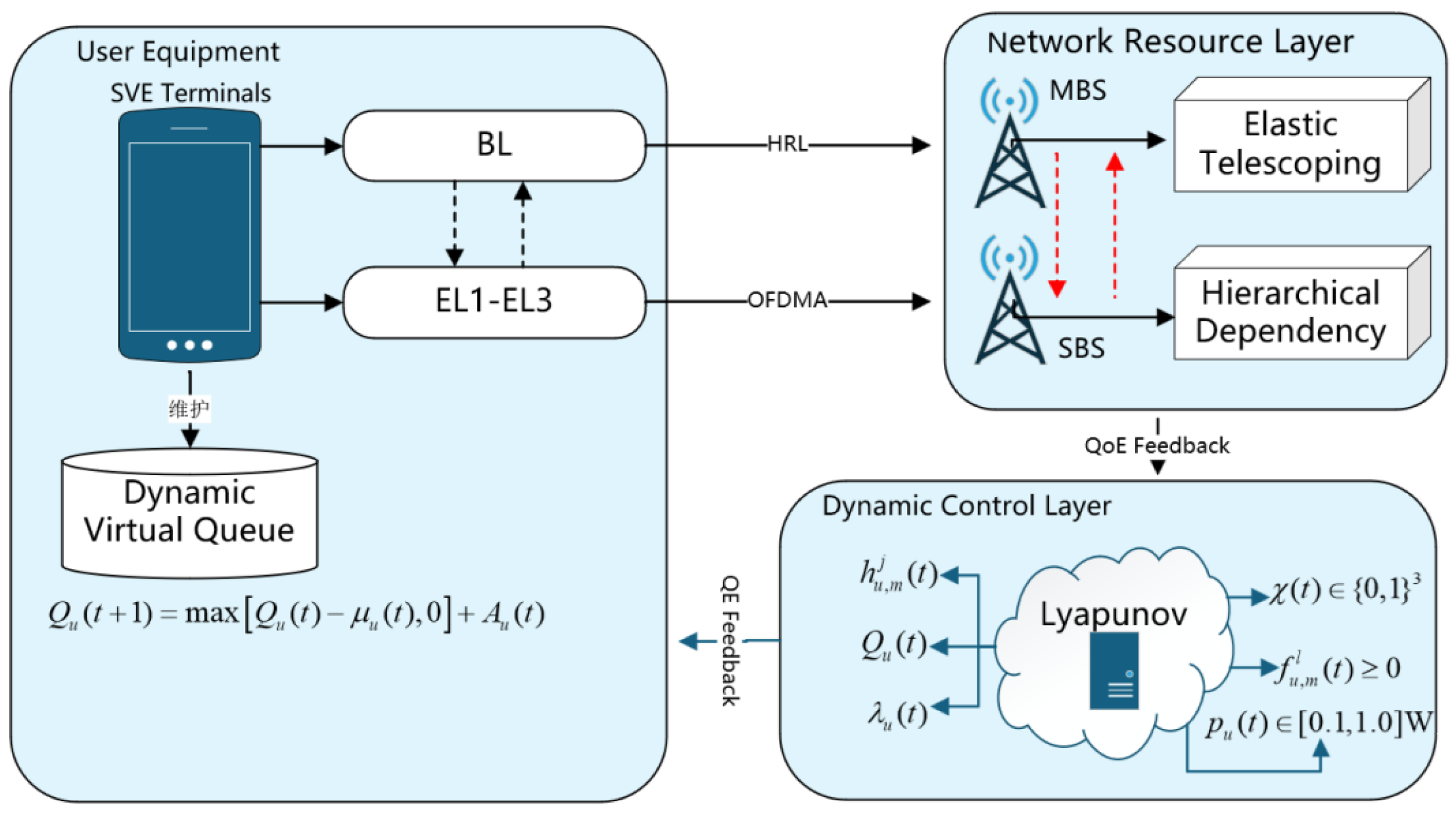
Figure 2.
The average time consumed by users varies with preference.
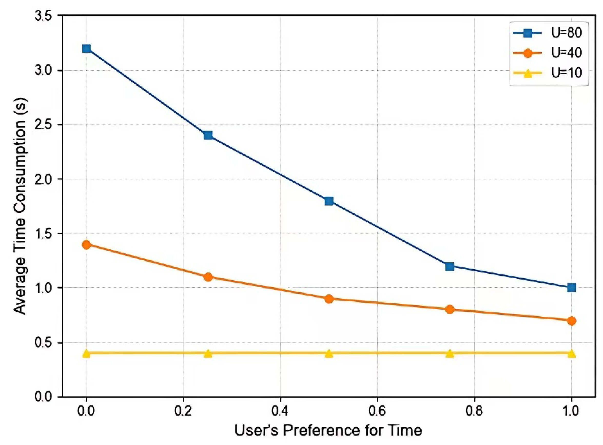
Figure 3.
The average energy consumption of the user varies with preference.
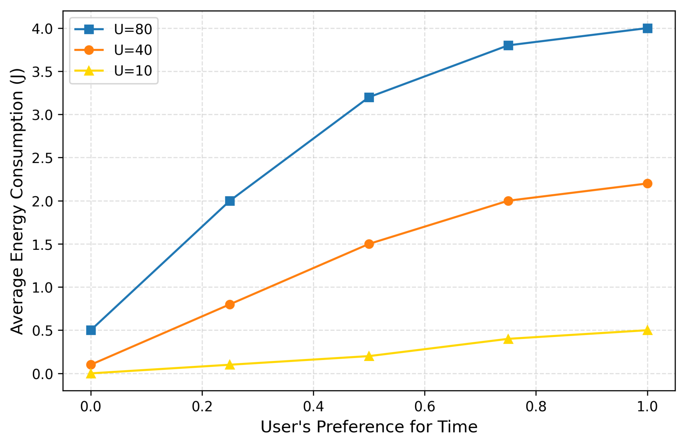
Figure 4.
Comparison of convergence speed and real-time performance of different algorithms.
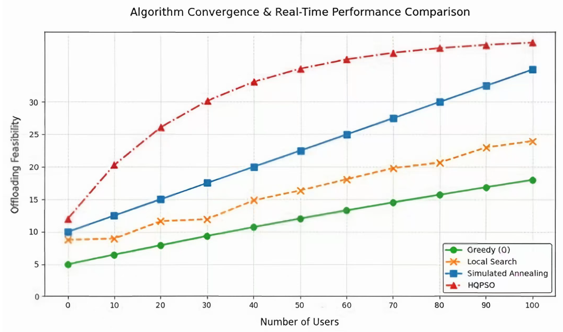
Figure 5.
Dynamic Robustness Comparison under Mobility Scenarios.
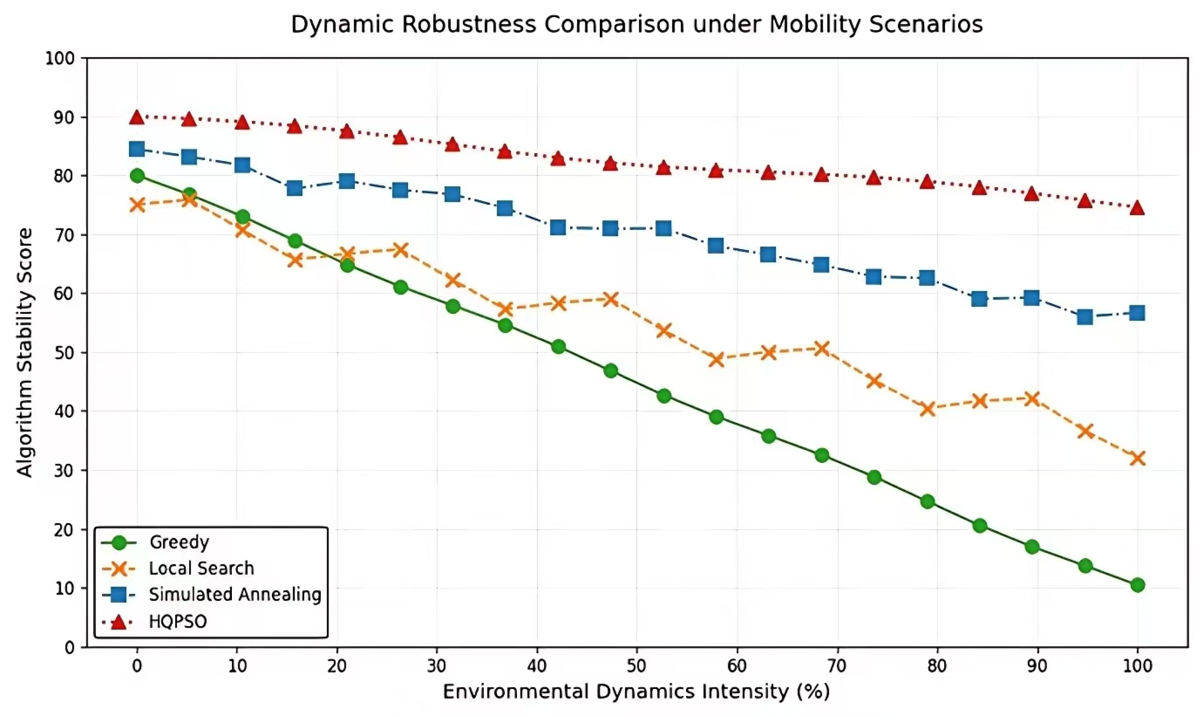
Figure 6.
Latency Performance Comparison under Mobility Scenarios.
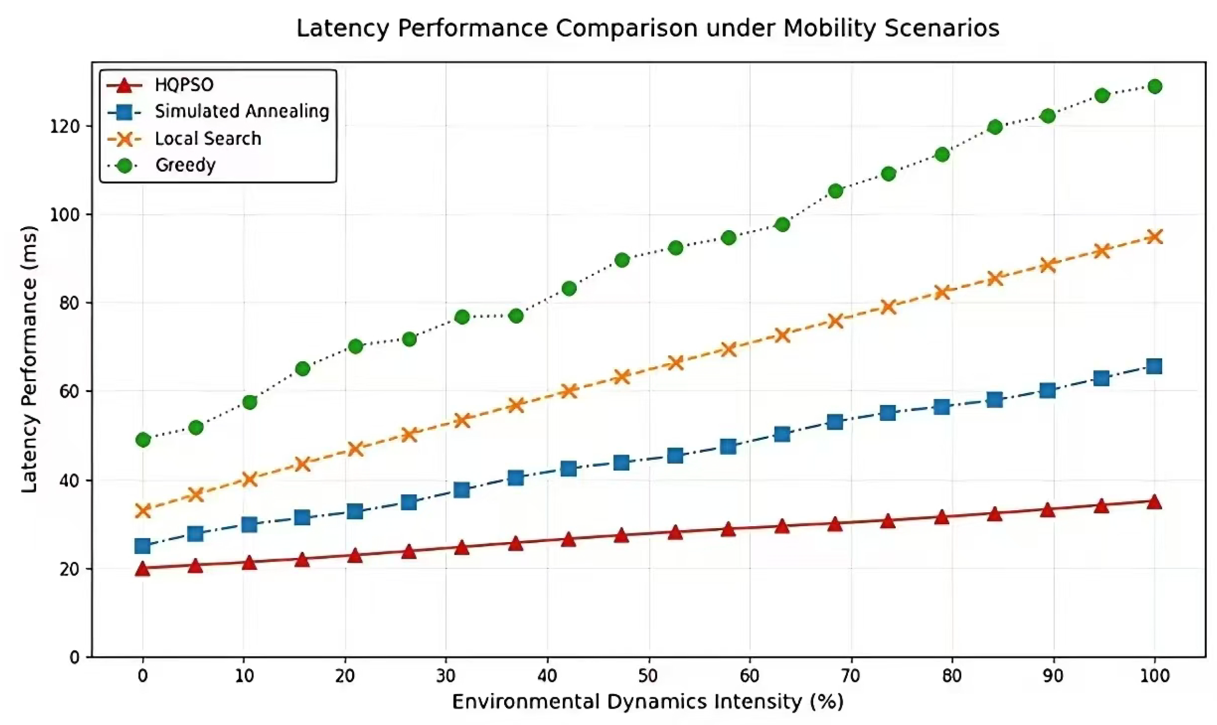
Figure 7.
Energy Efficiency Comparison under Dynamic Scenarios.
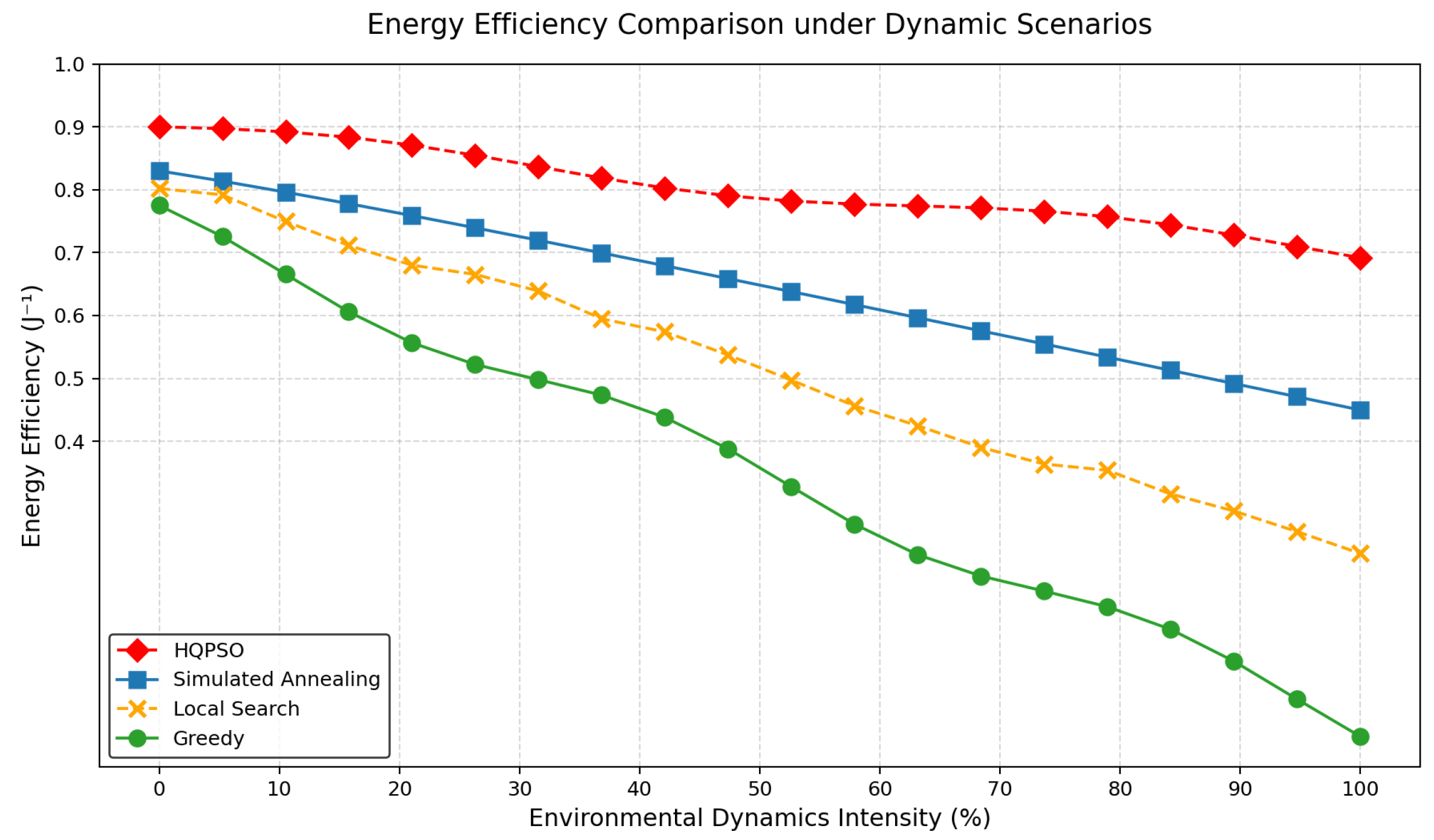
Figure 8.
Energy Efficiency Comparison under Dynamic Scenarios.
Disclaimer/Publisher’s Note: The statements, opinions and data contained in all publications are solely those of the individual author(s) and contributor(s) and not of MDPI and/or the editor(s). MDPI and/or the editor(s) disclaim responsibility for any injury to people or property resulting from any ideas, methods, instructions or products referred to in the content. |
© 2025 by the authors. Licensee MDPI, Basel, Switzerland. This article is an open access article distributed under the terms and conditions of the Creative Commons Attribution (CC BY) license (http://creativecommons.org/licenses/by/4.0/).
Copyright: This open access article is published under a Creative Commons CC BY 4.0 license, which permit the free download, distribution, and reuse, provided that the author and preprint are cited in any reuse.


