Submitted:
11 July 2025
Posted:
11 July 2025
You are already at the latest version
Abstract
Cement bond evaluation ensures wellbore integrity and zonal isolation in carbon capture, utilisation, and storage (CCUS) projects. This review examines various cement bond evaluation methods, focusing on acoustic logging and ultrasonic imaging tools. Their advantages, limitations, and recent advancements are analysed. This review also explores cement sheath deterioration over time, the impact of reactive fluids, and the emerging application of machine learning (ML) techniques to enhance evaluation accuracy and efficiency. Research gaps are identified in understanding long-term cement behaviour under CCUS conditions and the need for comprehensive 3D bond strength analyses. To address these gaps, this review recommends integrating ML and advanced modelling, standardising industry best practices, and exploring alternative materials to improve cement performance. Continued research and innovation are necessary to ensure a reliable cement bond evaluation, which is critical for the long-term success of CCUS projects.
Keywords:
cement bond evaluation
; cement degradation
; well integrity
; carbon capture
; acoustic logging
; ultrasonic logging
1. Introduction
1.1. Brief Overview of Carbon Capture, Utilisation, and Storage (CCUS)
Carbon dioxide (CO2) is generally regarded as the primary cause of global temperature increase due to its heat-trapping properties as a greenhouse gas [1]. Carbon capture, utilisation, and storage (CCUS) has gained considerable attention as a vital approach for mitigating greenhouse gas emissions in response to escalating concerns about climate change. CCUS involves the capture of CO2 emissions from various industrial processes and power plants, their transportation, and their injection into geological formations for long-term storage [2,3]. Therefore, CCUS technology is crucial for achieving carbon neutrality goals and reducing greenhouse gas emissions [4,5].
CCUS projects are rapidly expanding worldwide, with 41 in operation, 26 under construction, and 325 in the advanced and early development phases as of the end of 2023 [6]. Current trends include integrating circular carbon utilisation with partial geological sequestration, emphasising large-scale underground energy storage [5]. Additionally, there is a focus on upscaling CCUS projects in the Asia–Pacific region, with a shift towards multi-user hubs and synergy projects in the upstream sector [7]. These trends highlight the global momentum and diverse approaches in advancing CCUS technologies to combat climate change. Concurrently, there is increasing concern regarding the safety of long-term containment for underground carbon storage. A critical factor in addressing these safety concerns is ensuring the integrity of the wells used for carbon injection and storage. Well integrity, mainly achieved through effective cementing and completion practices, is essential to prevent leakage and maintain the long-term containment of stored CO2. By prioritising well integrity, CCUS projects can mitigate the risks associated with CO2 migration and ensure the secure storage of carbon dioxide over extended periods, thereby enhancing public confidence and the environmental credibility of geological carbon storage.
In carbon capture and storage (CCS) projects, brownfield and greenfield sites present distinct risks to the long-term containment of injected CO2. Brownfield sites are existing oil and gas fields that have been depleted and repurposed for CCS. In contrast, greenfield sites are previously undeveloped locations used for new CCS projects. One of the primary risks in brownfield CCS projects is the integrity of the existing wells in depleted fields. These wells, which can be several decades old, were not originally designed to handle high concentrations of CO2. The possibility of leakage along the wellbores due to accelerated corrosion, channelling, and cracks cannot be ignored and requires careful evaluation. Rigorous processes must be adopted to assess the feasibility of converting existing producers into CO2 injectors, as the design basis required for gas producers and CO2 injection wells differs significantly [8,9]. In greenfield CCS projects, the main concern is the design and completion of new wells, specifically for CO2 injection. Although the integrity of existing wells is not an issue, the casing point completion design must be optimised for long-term integrity rather than focusing solely on well injectivity. Both brownfield and greenfield CCS projects may require pressure management wells to control reservoir pressure during CO2 injection. These wells can experience different issues to injection wells, but they are still at risk of potential leakage points late in field life [10]. The careful monitoring and maintenance of pressure management wells are crucial to ensure the long-term containment of injected CO2.
A critical factor in ensuring the long-term containment of CO2 is maintaining the integrity of wells used for injection and storage. Well integrity refers to the ability of a well to prevent the uncontrolled release of fluids, including CO2, into the environment. It encompasses various aspects, including the structural integrity of the wellbore, the quality of cementing and completion practices, and the resistance of well materials to corrosion. Corrosion, in this context, refers to the degradation of well materials, such as steel casings, due to chemical reactions with CO2 and other formation fluids. In the context of CCUS projects, one critical aspect of well integrity that requires careful attention is the evaluation of cement bond quality. Cement bond evaluations are essential in ensuring the integrity and effectiveness of CCUS projects. By quantitatively assessing cement bond quality, the efficacy of zonal isolation and wellbore integrity can be guaranteed, which is essential for the long-term containment of captured CO2 and the prevention of its leakage into the environment [11,12]. Evaluating the strength of the cement bond to the formation is vital for maintaining structural integrity and preventing CO2 migration to the surface, thus ensuring the success of CCUS projects [13].
It is important to note that the evaluation techniques commonly used in the petroleum industry may not directly apply to CCUS projects due to several factors. One major factor is the operating conditions and objective differences between traditional oil and gas wells and CCUS projects. In oil and gas wells, the primary objective is to maximise hydrocarbon production. In contrast, in CCUS projects, the goal is to capture and store CO2 safely and effectively. This difference in objectives necessitates the development of specialised evaluation techniques for wellbore integrity in CCUS projects. Additionally, the composition and behaviour of CO2 differ from those of hydrocarbons, requiring specific considerations for cement bond evaluation. Therefore, developing specialised evaluation techniques tailored explicitly for wellbore integrity in CCUS projects is crucial.
1.2. Importance of Cement Bond Evaluation in CCUS Projects
Carbon capture and storage wells require a specialised design and construction to ensure long-term integrity and prevent CO2 leakage. The critical components of CCS wells include the casing, tubing, cement, and packers [14]. The cement placed around the casing provides zonal isolation and prevents CO2 migration. However, potential leakage pathways exist, such as through poor cementation, microannuli, and flow through the cap rock [15]. Geochemical reactions between cement and CO2-rich brine can cause deterioration, leading to changes in porosity, permeability, and mechanical properties. Mechanisms that could cause cement failure include the dissolution of primary minerals, the precipitation of carbonates, and the re-dissolution of carbonates [16]. Poor cement jobs, geochemical reactions, pressure, and temperature contribute to potential leakage [17]. To mitigate risks, CCS well designs should consider dual containment, material selection for corrosive environments, and periodic inspections. Maintaining proper cement integrity is crucial for preventing undetected CO2 migration from storage zones [18].
Maintaining a sealed outer annulus, the space between the outermost casing and the formation, is vital for ensuring the long-term integrity of the storage complex and preventing the potential leakage of injected CO2 in CCS projects [19]. This requirement is particularly critical for well components that penetrate the primary caprock and extend into the storage reservoir. These components represent potential pathways for CO2 migration from the intended storage zone. A competent cement seal in the outer annulus prevents vertical fluid migration, unintended fluid communication between the geological layers, and CO2 leakage through the annular space. Failure to robustly seal the outer annulus, particularly in areas where the wellbore passes through permeable formations or faults, could compromise the effectiveness of the storage project and lead to environmental and safety hazards.
Figure 1 illustrates the possible leakage pathways of CO2 gas through several mechanisms, such as small gaps near the casing–cement or cement–formation boundary; channelling along the cement; and the quality of the cement itself, which can deteriorate over time.
The length of the cement zone plays a vital role in ensuring the long-term integrity and containment of injected CO2 in CCS sites. There is no universally prescribed minimum length for the cement zone. Instead, the required length is determined by a combination of site-specific factors and regulatory requirements. Geologic characteristics such as the depth of the injection zone, the presence of overlying cap rock, and the potential for fluid migration through faults or fractures all influence the cement zone length required to isolate the storage reservoir effectively. Moreover, the anticipated pressure and temperature conditions during injection and the chemical compatibility between the cement and formation fluids must be considered when designing an adequate cement barrier. Regulatory frameworks, which vary by jurisdiction, typically stipulate minimum cement zone requirements based on these site-specific factors and industry best practices. For instance, NORSOK D-010, used in Norway, emphasises the importance of proper cement coverage to ensure well integrity without specifying a fixed minimum length [21]. ISO 16530 and ISO 27914 also provide recommendations for cement zone design and verification without prescribing specific minimum lengths. Similarly, the regulatory framework for CCS in Australia, outlined in documents such as the “Regulatory Guiding Principles for Carbon Dioxide Capture and Geological Storage” and the “Offshore Petroleum and Greenhouse Gas Storage Act 2006”, requires detailed assessments of the proposed reservoir and risk mitigation strategies rather than adherence to a fixed minimum length across all projects [22,23].
CCS projects must ensure well integrity to guarantee the safe and secure long-term storage of CO2. After construction, combinations of pressure tests, cement bond logs, acoustic logging techniques, fibre optic distributed acoustic sensing (DAS), and temperature sensing (DTS) are employed to assess the well’s mechanical strength and sealing capacity and to identify potential leakage pathways [24,25]. Throughout the operational life of the well, continuous monitoring methods, such as annulus pressure monitoring, downhole sensors, and gas detectors, are utilised to detect any signs of integrity issues. When repurposing old wells for CCS, a rigorous evaluation is conducted by reviewing the original well design, construction materials, and completion methods to determine their compatibility with CO2 injection requirements [26]. This may involve using corrosion-resistant alloys and CO2-resistant cement and conducting comprehensive logging and testing to identify weaknesses in the existing well structure. The geomechanical modelling and analysis of in situ stress conditions are also crucial to determine the maximum safe injection pressures and avoid fracturing the formation [27]. Based on risk assessment, old wells may be categorised as suitable for reuse, requiring remedial work, or unsuitable for CCS. The decision to reuse an old well depends on a thorough evaluation of its integrity, the costs of any necessary remedial work compared with those of drilling a new well, and the overall risk profile of the CCS project [28].
In contrast to new wells, legacy wells initially designed for oil and gas production often lack comprehensive records of their construction and cement integrity. This necessitates new logging runs to assess their suitability for CCS. Legacy wells may not have been designed to withstand the corrosive nature of CO2-rich fluids or ensure a long-term sealing capacity. Evaluating these wells involves reviewing the available records, followed by targeted logging and testing to identify potential leakage pathways or weaknesses, which can be complicated by multiple casing layers [29]. However, new wells explicitly drilled for CCS incorporate CO2-resistant materials and specialised components such as CO2 injectors and monitoring systems [30]. They undergo initial post-construction testing and ongoing monitoring using methods such as distributed acoustic sensing (DAS), temperature sensing (DTS), and periodic wireline logging with advanced tools such as pulsed-neutron logs [31]. The inclusion of CO2 injectors and water producers in new wells adds complexity, as the long-term effects of CO2 exposure on cement and well materials must be carefully considered, often through geochemical modelling and simulation [32]. Challenges in evaluating legacy wells include the lack of a unified data structure, the need to estimate cement bond and barrier permeabilities, and the potential for undetected leakage pathways owing to outdated well designs or materials. To address these challenges, a risk-based approach is often used, involving the development of methodologies to estimate potential CO2 leakage rates and support decision-making in site screening and selection [28].
1.3. Objectives of this Review
This review aims to examine cement bond evaluation techniques explicitly tailored for CCUS projects. Through a thorough analysis of the existing literature and case studies, this review seeks to identify the key challenges and advancements in cement bond evaluation for CCUS. Furthermore, this review aims to outline future directions and recommendations to enhance the reliability and effectiveness of cement bond evaluation in the context of carbon storage.
This review aims to thoroughly investigate different methods for assessing cement bonds in the context of CCUS projects. To this end, a comprehensive review of the current literature and an analysis of relevant case studies are conducted. This study seeks to identify not only significant obstacles but also critical advancements in cement bond evaluation for CCUS. Moreover, it aims to suggest future avenues and provide recommendations to enhance the reliability and effectiveness of these evaluations within the framework of carbon storage projects.
2. Cement Bond Evaluation Techniques
2.1. Description of Cement Bond Logging Tools
Cement bond evaluation is crucial for ensuring wellbore integrity, particularly in the context of CO2 injection for carbon storage. Various logging tools have been used for cement bond evaluation, each with distinct technologies and applications. The primary logging tools used for cement bond evaluation are acoustic and ultrasonic tools and other technologies, such as temperature logging, noise logging, oxygen activation logs, neutron–neutron logging, and fibre optic measurements [33,34]. Acoustic tools, such as pulse-echo and flexural measurements, are the leading techniques for cement job evaluation. Acoustic logging is the primary method used to assess cement bond quality, allowing an analysis of casing and formation waves [33,35]. In recent years, ultrasonic tools have gained traction in the industry and have been developed to provide a high-quality assessment of cement bond quality [36].
However, these tools differ in their operating principles and applications. The cement bond log (CBL) is one of the most commonly used tools for evaluating cement bond quality. Acoustic waves measure the amplitude and travel time of sound waves propagating through the cement, casing, and formation. The CBL provides a quantitative indication of cement bond quality by comparing the amplitude and travel time of the reflected waves from different interfaces. This tool assesses casing annular conditions and provides measurements related to the cement quantity, compressive strength, and bonding to the pipe and formation. CBL tools are essential for determining the isolation of cement and ensuring its zonal integrity [37,38]. Despite its wide use, the CBL has its limitations. One limitation is that the CBL measures the average travel time and amplitude around the borehole. If there is any issue with the quality of the cement bond, then one cannot determine on which side of the borehole the issue lies because the CBL does not provide azimuth information. With advances in technology, new tools have been developed.
One example is the segmented bond tool (SBT) [39]. The SBT measures attenuation similar to the CBL attenuation, including azimuthal information (60-degree coverage per segment) to determine the location of any potential cement bond issues around the borehole. Figure 2 provides a comparison of CBL and SBT data. In CBL data, the attenuation is an average reading from around the wellbore. Therefore, there is no way to tell which part of the wellbore requires more attention.
Meanwhile, with the additional azimuthal information from the SBT, the area with possible poor cement bonding can be located more accurately. Further improvements in the acoustic logging tool led to a new tool called the azimuthally acoustic bond tool (AABT 2.0), which offers an enhanced azimuth resolution capability that can be useful for determining the azimuth and angle range of cement channelling [35]. This tool uses phased-arc array transmitters to provide detailed evaluations of cement bond quality in different directions around the wellbore.
In recent years, there has been an increased focus on developing and utilising ultrasonic tools for cement bond evaluation in the industry. These tools utilise ultrasonic waves to assess the quality of the cement bond. Ultrasonic logging tools effectively provide indirect measurements of cement quality. They are commonly used to detect the presence of cement behind pipes and evaluate the bond strength between cement and formations [34,40]. Ultrasonic logging tools typically use a broadband pulse (200–700 kHz), which is much higher than the pulse used by the conventional CBL. These higher frequencies allow for more detailed and accurate evaluations of the cement bond because they are better able to detect small air voids or microannuli that may exist in the cement sheath. However, compared with acoustic logging tools, ultrasonic logging tools are more sensitive to irregularities around the pipe, such as pipe rugosity or the presence of corrosion or deposits, which can affect the accuracy of the measurements. Moreover, using high frequencies in ultrasonic logging tools limits their use in heavy mud such as oil-based mud (OBM).
For well integrity evaluation, acoustic logging tools are standard for indirectly measuring cement quality and finding the top of cement (TOC). However, they have limitations in measurement and interpretation accuracy [34]. Ultrasonic tools are preferred for their high-resolution imaging capabilities, and they are extensively used for cement bond evaluation [36]. Other technologies such as logging-while-drilling (LWD) sonic tools offer alternatives for cement bond evaluations, especially in scenarios where wireline operation is not feasible [41,42]. Additionally, new technologies are being developed to evaluate the cement quality behind multiple casing layers in a single logging run, which can be cost-effective for well abandonment [43].
2.2. Principles of Acoustic Logging and Ultrasonic Imaging Tools
Acoustic logging tools are essential for evaluating cement bond integrity, particularly in the context of carbon sequestration or CCUS projects. These tools utilise sound waves to examine the cement bond quality between the casing and formation. By assessing the travel time and amplitude of the reflected waves, acoustic logging tools offer detailed insights into the bonding strength and integrity of the cement sheath [44,45,46]. The process of generating and analysing acoustic waves with logging tools is initiated by emitting sound pulses from a transmitter into the wellbore. These sound waves propagate through the casing, cement sheath, and formation, encountering interfaces that reflect some energy to the receiver. The received signals are then processed to extract information about the acoustic properties of the materials, including the cement bond quality. Several parameters measured during acoustic logging include the following:
- Transit Time: This parameter reflects the acoustic impedance of the encountered materials, with variations indicating changes in material properties, such as bonding strength.
- Amplitude: The strength of the received acoustic signal correlates with material density and integrity. Lower amplitudes suggest poor bonding or the presence of a microannulus in the cement sheath.
- Attenuation: This parameter provides information about the material’s acoustic properties and cement bond quality based on the reduction in the strength of the signal as it propagates through the wellbore, casing, and cement.
- Oscilloscope Pictures: Visual representations of acoustic signals help to interpret cement bond quality and identify issues such as fluid annulus thickness or poor bonding.
By analysing the amplitude, travel time, and attenuation of reflected waves, operators can evaluate the integrity of the cement bond and identify potential issues, such as microannuli or poor bonding [47,48,49].
Figure 3 shows a schematic of acoustic waveforms in a cement bond log. Different cement bond conditions will give different amplitude characteristics at different travel times. In this figure, the 57 µs/ft line represents a signal from the casing (casing–cement boundary). The significantly high amplitude right after the casing represents the possibility of a free pipe, resulting from an acoustic signal resonating along the casing.
A well-bonded cement sheath shows consistent transit times, high amplitudes, and low attenuation levels, indicating effective zonal isolation and wellbore integrity. Conversely, poor bonding, microannuli, or fluid channels behind the casing may lead to longer transit times, reduced amplitudes, and increased attenuation, signalling potential cement bond issues [50,51]. The analysis of acoustic waves during logging offers detailed information on material acoustic properties, enabling operators to evaluate the cement bond quality and identify anomalies that could compromise wellbore integrity. By measuring transit times, amplitudes, and attenuation levels, acoustic logging tools provide a comprehensive assessment of the cement bond; aid operators in identifying potential anomalies that could compromise wellbore integrity; and allow for informed decisions to be made regarding well construction, maintenance, and CCUS operations.
Ultrasonic imaging tools employ a rotating transducer to emit and receive ultrasonic waves, generate cross-sectional images of the annular space, and identify areas with poor cement bonds. The high-frequency broadband pulses used by ultrasonic imaging tools cause a part of the casing to vibrate. This vibration can die off rapidly or slowly, depending on the material behind the casing. Some energy is reflected to the tool, and some continues propagating through the casing wall until it is completely attenuated. As a result, the reflected waves recorded by the transducers contain resonances. Some measurements taken by ultrasonic imaging tools include the following:
- Echo amplitude: This is an indicator of casing conditions.
- Internal radius of the casing: This is calculated from the transit time of the main echo.
- Casing thickness: This value is calculated from the resonant frequency.
- Acoustic impedance of the material behind the casing: This is calculated from the resonance form.
The resonance is strong when fluid is behind the casing, and it is weaker if there is solid cement behind the casing. The different resonance characteristics determine the acoustic impedance value of the cement. The cement impedance value can be displayed in a 3D view, which provides full spatial coverage around the wellbore. After applying a threshold value to the cement impedance, areas with relatively low impedance values could be flagged as poor bond intervals with liquid or gas filling.
Zemanek et al. [52] could be considered the first to introduce early-generation ultrasonic technology with a tool called the borehole televiewer (BHTV). Subsequently, other advancements in ultrasonic imaging tools were made to keep up with the demand from the industry. One such advancement is the cement evaluation tool [53], which uses an ultrasonic pulse with an array of eight transducers, each covering an azimuthal area of 45°. Hayman et al. [54] introduced the second generation of ultrasonic tools with a tool called the ultrasonic imager (USI). This tool uses a single rotating transducer to achieve greater accuracy in covering the pipe circumference. It also incorporates improved model-based signal processing, which is less sensitive to environmental effects. Graham et al. later developed a similar tool called circumferential acoustic scanning tool-visualisation (CAST-V) [55]. Advancements in ultrasonic imaging tools have recently been made by several companies [56,57,58] aiming to overcome the challenges related to cement integrity evaluation in more extreme environments.
2.3. Advantages and Limitations of Acoustic Logging and Ultrasonic Imaging Tools
Both acoustic logging and ultrasonic imaging have advantages and limitations, influencing their selection and use in cement bond evaluations for CCUS projects. As an early-generation tool for cement bond evaluation, acoustic logging tools have been developed with a high degree of sophistication, offering reliable assessments essential for confirming well integrity [42]. Acoustic logging tools offer real-time assessment capabilities, allowing operators to promptly identify bonding issues, such as microannuli or poor bonding. Providing immediate feedback on cement bond conditions enables quick decision-making and intervention to ensure zonal isolation and wellbore integrity. Additionally, acoustic logging tools offer extensive wellbore coverage, allowing operators to visualise the cement bond conditions surrounding the well casing and comprehensively evaluate cement integrity [50,59]. These advantages make acoustic logging tools valuable for assessing cement bond quality in CCUS projects. However, these tools have some limitations. Conventional acoustic logging tools can struggle with azimuth and angle range resolution when evaluating channelling, which has led to the development of improved tools, such as the azimuthally acoustic bond tool (AABT 2.0), for enhanced resolution [35].
However, ultrasonic imaging techniques provide detailed visualisations of the cement bond conditions, offering valuable insights into zonal isolation and well integrity. The high-resolution imaging capability of ultrasonic tools allows for the identification of small-scale defects that may not be easily detectable with an acoustic logging tool. Figure 4 displays an example of data from the ultrasonic logging tool. The data in track 3 on the right show an acoustic waveform from the CBL compared with other tracks from ultrasonic logging. This detailed visualisation enables precise assessments of the cement bond integrity, which is crucial for the success and safety of wellbore operations, as in CCUS projects. However, ultrasonic imaging techniques face limitations and challenges, particularly in high-pressure and high-temperature wells. Signal distortion and attenuation in these environments can affect the accuracy of imaging results, thereby affecting the reliability of the assessment. Additionally, interpreting ultrasonic imaging data in complex well environments requires specialised expertise and calibration to evaluate cement bond integrity accurately. The complexity of well environments, such as multiple casings or intricate geometries, can present challenges for ultrasonic imaging techniques, affecting the comprehensive evaluation of cement bond conditions [60].
In CO2 injector wells, the advantages of acoustic logging tools, such as real-time assessment and extensive wellbore coverage, are particularly beneficial for quickly identifying and addressing bonding issues. The limitations of ultrasonic imaging techniques, such as signal distortion and challenges in complex well environments, may pose challenges in accurately assessing cement bond integrity under these conditions. Therefore, operators may need to carefully consider the trade-offs between the advantages and limitations of acoustic logging tools and ultrasonic imaging techniques when selecting the most suitable method for cement bond evaluation in high-pressure and high-temperature CO2 injector wells in CCUS projects.
3. Challenges in Cement Bond Evaluation for CCUS
3.1. Presence of CO2 and Other Reactive Fluids
The interaction between CO2 and cementitious materials in carbon capture, utilisation, and storage (CCUS) wells complicates cement bond evaluation due to its role in accelerating cement degradation. Portland cement, the most commonly used material in oil and gas wells, is valued for its sealing properties and ability to prevent fluid migration, making it suitable for drilling operations. However, its performance in CCUS wells is compromised by its vulnerability to degradation when exposed to CO2-rich environments and reactive fluids. This degradation primarily occurs through carbonation, which significantly weakens the mechanical properties of the cement. As a result, Portland cement’s suitability for such applications is increasingly being questioned [61].
Alternatives such as geopolymers and non-Portland cement are being actively explored due to their superior chemical resistance and durability in CO2-rich conditions [62,63]. These materials offer a higher compressive strength, more excellent chemical stability, and improved resistance to CO2, making them promising candidates for mitigating the risk of structural degradation and CO2 leakage. Additionally, Portland cement’s resilience can be enhanced with additives such as nanomaterials, smectite clay waste, or pozzolanic substances, which improve resistance to carbonation and aggressive fluids [64,65,66]. However, the long-term effectiveness of these enhanced formulations in preventing CO2 leakage remains under investigation.
When exposed to wet supercritical CO2 under reservoir conditions, Portland cement experiences carbonation, altering its microstructure and diminishing its mechanical properties [67]. This degradation is compounded by the presence of aggressive fluids in real-world applications such as CO2-enhanced oil recovery (CO2-EOR), CO2/H2S co-sequestration, and matrix acidification [68]. The altered cement structure weakens the annular seal, increasing the risk of CO2 leakage [69]. Studies have emphasised the need to better understand these degradation mechanisms, mainly how compressive stress influences cement integrity during CO2 attacks [32,70].
Cement degradation significantly threatens the long-term success of CCUS projects by compromising wellbore integrity and increasing the likelihood of CO2 leakage. Prolonged exposure to CO2 alters both the transport and mechanical properties of the cement, leading to the formation of preferential pathways for fluid migration [69,71]. These pathways further weaken the cement sheath, increasing the risk of wellbore failure and allowing CO2 to escape to the surface, posing environmental hazards [72].
The changes in the hydraulic properties of wellbores due to cement degradation can also lead to the migration of subsurface greenhouse gases and brines [73]. Moreover, reductions in compressive and shear bond strengths heighten the risk of wellbore failure over time [74]. These challenges underscore the urgent need for robust cementing strategies and the development of CO2-resistant cement formulations to ensure the long-term safety and effectiveness of carbon sequestration [68,75,76].
Accurately assessing cement bond quality in the presence of reactive fluids such as CO2-rich brine necessitates the adoption of advanced evaluation techniques. One promising approach is using novel ultrasonic cased-hole imagers designed explicitly for enhanced cement evaluation [77]. These tools provide a detailed visualisation and assessment of the cement bond quality behind the casing, offering critical insights into the integrity of cement sheaths in CCUS wells.
Advancements in cement bond evaluation using well logs also present valuable opportunities. By leveraging well log data and interpretation techniques, operators can effectively assess the cement bond with the casing and formation, even under challenging reservoir conditions, providing a comprehensive understanding of cement integrity [78]. Furthermore, applying enhanced ultrasonic measurements, combining traditional pulse-echo techniques with innovative flexural wave concepts, allows for a more comprehensive evaluation of cement properties and bond integrity [79]. These innovative approaches provide operators with the tools and materials necessary to accurately evaluate and ensure long-term cement integrity in CCUS environments, contributing to the overall success and safety of carbon sequestration projects.
3.2. Impact of Cement Sheath Deterioration over Time
The cement sheath can deteriorate through various mechanisms over time, impacting zonal isolation and well integrity. One significant mechanism is the formation of a microannulus at the cement–sheath interface, leading to issues such as annular pressures, crossflows between reservoirs, and flow behind the casing [80]. Changes in wellbore temperature and pressure during fracturing and flow back can induce stress variations in the cement sheath, potentially causing compression, tensile failure, or micro-clearance between the casing and the cement sheath [81]. Additionally, sudden thermomechanical fatigue failure can lead to microannuli and fractures in the cement sheaths [82].
In addition to mechanical degradation, chemical degradation is a concern in CCUS environments. Exposure to CO2 can alter chemical equilibria and lead to reactions that compromise cement integrity [83]. These reactions can result in the formation of microannuli, cracks, and leakage pathways for CO2, jeopardising the effectiveness of carbon sequestration [82]. Therefore, understanding and mitigating mechanical and chemical degradation mechanisms are crucial for ensuring the long-term sustainability of cement sheaths in CCUS projects.
Effectively managing the long-term risks associated with cement sheath integrity in CCUS wells necessitates a multifaceted approach. Advanced monitoring technologies, such as downhole sensors, provide real-time data on temperature, pressure, and stress variations within the wellbore [84]. These real-time data enable the proactive identification and mitigation of potential cement degradation issues. Furthermore, developing and utilising predictive models based on computational simulations are essential. These models, incorporating factors such as material properties and wellbore dynamics, can forecast the long-term behaviour of the cement sheath under varying reservoir conditions, aiding in the design of robust cementing strategies and informing maintenance schedules [85].
In addition to monitoring and prediction, utilising innovative materials is vital to enhancing cement sheath resilience. Incorporating engineered additives with expansive properties or enhanced durability into cement formulations can significantly improve long-term performance and reduce the likelihood of degradation [86]. By integrating these advanced monitoring strategies, predictive modelling techniques, and novel material solutions, operators can effectively assess and mitigate the long-term risks associated with cement deterioration, ensuring the integrity and effectiveness of CCUS operations while minimising environmental impact.
4. Advances in Cement Bond Evaluation Techniques
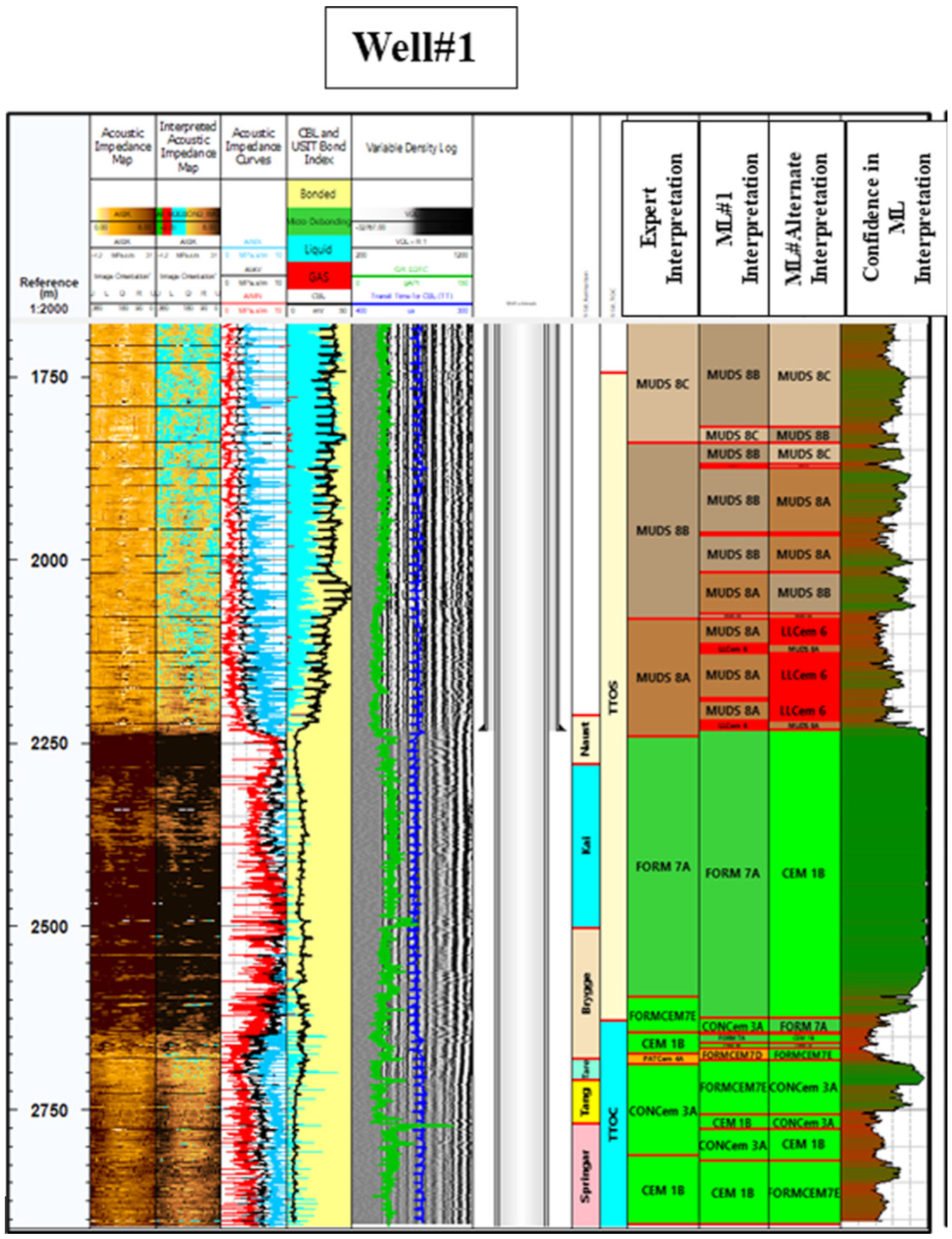
Applying machine learning (ML) and artificial intelligence (AI) in cement bond evaluation presents a significant advancement for CCUS projects. ML algorithms, trained on diverse datasets, including ultrasonic and sonic logs, offer the potential for a more accurate and efficient assessment of cement bond integrity. AI-driven predictive models can identify patterns and predict bond quality, leading to improved decision-making in well construction and monitoring [11,87,88,89]. The benefits include enhanced evaluation accuracy and efficiency, real-time insights into cement quality for proactive maintenance, and the identification of potential issues such as crossflow, preventing costly well failures [90]. Additionally, AI facilitates the development of predictive maintenance strategies to optimise the performance and longevity of CCUS projects. Figure 5 compares the results of ML-assisted interpretations with human expert interpretations. In this example, ML-assisted interpretations show very similar results to human expert interpretations in many intervals, proving that machine learning can significantly contribute to accurately evaluating cement bond integrity.
However, challenges remain in fully leveraging AI for cement bond evaluation. The reliance on high-quality data for training AI algorithms can be limiting, as such data may not always be readily available or may require extensive pre-processing [89]. Furthermore, the interpretability of AI models is crucial, as stakeholders need to understand the rationale behind AI-driven decisions. Additionally, the initial investment required for implementing AI technologies can be a barrier for some organisations [90].
Several research gaps need to be addressed to enhance the accuracy and reliability of AI-based cement bond evaluation. Firstly, advanced methods for accurately interpreting ultrasonic data for casing annulus characterisation are needed [92]. Secondly, current research primarily focuses on single-slice image analysis, highlighting the need for comprehensive 3D analysis techniques to evaluate cement-to-formation bond strength [11]. Lastly, while ML has been explored for cement quality risk assessment [93], there is a lack of research integrating experimental analysis with ML to assess bond performance and corrosion severity.
Several strategies can be implemented to address these gaps: Developing autonomous interpretation methods leveraging ML can allow for the accurate characterisation of borehole properties and casing annulus features [92]. Additionally, advancing imaging techniques to enable a comprehensive 3D analysis of bond strength is crucial [11]. Finally, integrating experimental analysis with ML can provide a more holistic understanding of bond performance and corrosion. These advancements will significantly enhance the accuracy and reliability of cement bond evaluation, improving well integrity and zonal isolation for the long-term success and safety of CCUS projects.
5. Conclusions and Recommendations
This review underscores the critical role of accurate cement bond evaluation in ensuring the success and safety of CCUS projects. While advancements have been made in evaluation techniques, significant research gaps remain, particularly regarding the long-term behaviour of cement in the high-pressure, high-temperature environments typical of CCUS reservoirs. Further investigation is needed to fully understand the complex interactions between cement and reactive fluids such as CO2 and to develop effective mitigation strategies against degradation.
Several recommendations are proposed to enhance the reliability and effectiveness of cement bond evaluation in CCUS. Firstly, integrating machine learning and advanced modelling techniques into evaluation workflows can significantly improve assessment accuracy and provide valuable insights for optimising cement performance under challenging conditions. Secondly, standardising best practices and protocols across the industry ensures the consistency and comparability of results, fostering collaboration and knowledge sharing. Finally, exploring the development of alternative materials and novel cementitious systems, such as geopolymers, can offer further avenues for improvement. Through continued collaboration and innovation among researchers, industry stakeholders, and policymakers, we can overcome existing challenges and advance cement bond evaluation techniques to ensure the long-term success of CCUS initiatives.
Author Contributions
Conceptualization, methodology, writing—original draft preparation, P.A.; writing—review and editing, supervision, R.R. and B.C. All authors have read and agreed to the published version of the manuscript.
Funding
This research received no external funding.
Conflicts of Interest
The authors declare no conflict of interest.
References
- Nanthakumar, C.; Sakthikumaran, M.; Sivashankar, G. Carbon Dioxide—The Frontline Greenhouse Gas. Int. J. Comput. Algorithm 2021, 10, 47–53. [Google Scholar] [CrossRef]
- Carpenter, C. Study Describes Challenges, Opportunities of CO2 EOR in China. J. Pet. Technol. 2022, 74, 87–89. [Google Scholar] [CrossRef]
- Orr, F.M. Carbon Capture, Utilization, and Storage: An Update. SPE J. 2018, 23, 2444–2455. [Google Scholar] [CrossRef]
- Che, X.; Yi, X.; Dai, Z.; Zhang, Z.; Zhang, Y. Application and Development Countermeasures of CCUS Technology in China’s Petroleum Industry. Atmosphere 2022, 13, 1757. [Google Scholar] [CrossRef]
- Hou, Z.; Luo, J.; Xie, Y.; Wu, L.; Huang, L.; Xiong, Y. Carbon Circular Utilization and Partially Geological Sequestration: Potentialities, Challenges, and Trends. Energies 2022, 16, 324. [Google Scholar] [CrossRef]
- Global CCS Institute, Facility Data. 2024. Available online: https://app.powerbi.com/view?r=eyJrIjoiM2ZiOGM4ODMtYzU0ZS00NzVlLTkyNjgtY2EwYzg0ZWVmMGI1IiwidCI6IjRlMjRkMDI2LWI5MTYtNGNiMS04YWZmLTI1ZmZhNzA1ZWVhMSIsImMiOjEwfQ%3D%3D (accessed on 9 June 2024).
- Dimabuyu, A. Upscaling CCUS in Asia Pacific—A look at upstream synergy projects and potential for multi-user hubs. APPEA J. 2023, 63, S371–S374. [Google Scholar] [CrossRef]
- Picha, M.S.; Abu Bakar, M.A.B.; Patil, P.A.; Abu Bakar, F.A.; Das, D.P.; Tiwari, P.K. Overcoming CO2 Injector Well Design and Completion Challenges in a Carbonate Reservoir for World’s First Offshore Carbon Capture Storage CCS SE Asia Project. In Proceedings of the Abu Dhabi International Petroleum Exhibition & Conference, Abu Dhabi, United Arab Emirates, 15–18 November 2021. [Google Scholar] [CrossRef]
- Picha, M.S.; Chuttani, A. Storage Development Plan SDP for Abandoning High Risk Development Wells and Drilling Fit-For-Purpose CO2 Injectors Offshore Carbon Capture Storage CCS Project. In Proceedings of the IADC/SPE Asia Pacific Drilling Technology Conference and Exhibition, Bangkok, Thailand, 9–10 August 2022. [Google Scholar] [CrossRef]
- Picha, M.S. Carbon Capture Storage (CCS) Drilling & Completion Well Integrity Lifecycle Challenges & Mitigations. In Proceedings of the SPE/IADC Asia Pacific Drilling Technology Conference and Exhibition, Bangkok, Thailand, 7–8 August 2024. [Google Scholar] [CrossRef]
- Bathija, A.P.; Sengupta, M.; Eichmann, S.L. Method of evaluating cement-to-formation bond strength with computed tomography image analysis. Lead. Edge 2022, 41, 611–616. [Google Scholar] [CrossRef]
- Santos, L.; Taleghani, A.D. On Quantitative Assessment of Effective Cement Bonding to Guarantee Wellbore Integrity. J. Energy Resour. Technol. 2021, 144, 013001. [Google Scholar] [CrossRef]
- Carpenter, R.B.; Brady, J.L.; Blount, C.G. The Effects of Temperature and Cement Admixes on Bond Strength. J. Pet. Technol. 1992, 44, 936–941. [Google Scholar] [CrossRef]
- Gaurina-Meðimurec, N.; Pasic, B. Design and Mechanical Integrity of CO2 Injection Wells/Konstrukcija I Mehanicka Cjelovitost Busotina Za Utiskivanje CO2. Rud.—Geolosko—Naft. Zb. 2011, 23, 1–8. [Google Scholar]
- Gaurina-Medjimurec, N.; Pasic, B. Chapter 15: CO2 Underground Storage and Wellbore Integrity. In Risk Analysis for Prevention of Hazardous Situations in Petroleum and Natural Gas Engineering; Advances in Environmental Engineering and Green, Technologies; Matanovic, D., Simon, K., Eds.; IGI Global: Hershey, PA, USA, 2014; pp. 322–357. ISBN 978-1-4666-4777-0. [Google Scholar]
- Mura, M.; Sharma, M.M. Mechanisms of Degradation of Cement in CO2 Injection Wells: Maintaining the Integrity of CO2 Seals. In Proceedings of the SPE International Conference and Exhibition on Formation Damage Control, Lafayette, LA, USA, 21–23 February 2024; p. D011S006R004. [Google Scholar] [CrossRef]
- Gholami, R.; Raza, A.; Iglauer, S. Leakage risk assessment of a CO2 storage site: A review. Earth-Sci. Rev. 2021, 223, 103849. [Google Scholar] [CrossRef]
- Ceyhan, I.; Pilisi, N.; Suryanarayana, P.V.; Krishnamurthy, R.M. Design of Carbon Capture and Sequestration CCS Wells. In Proceedings of the IADC/SPE International Drilling Conference and Exhibition, Galveston, TX, USA, 8–10 March 2022; p. D021S018R001. [Google Scholar] [CrossRef]
- Chadwick, A.; Holloway, S.; Hannis, S.; Rochelle, C.; Williams, J.; Mackay, E.; Ford, J.; Pickup, G.; Somerville, J.; Tohidi, B. External Review of the Storage Plan for the Peterhead Carbon Capture and Storage Project; British Geological Survey: Nottingham, UK, 2015. [Google Scholar]
- Alberdi-Pagola, P.; Fischer, G. Review of Integrity Loss Detection and Quantification Due to Cracking in Cemented Wells. SPE J. 2023, 28, 965–982. [Google Scholar] [CrossRef]
- NORSOK D-010:2021+AC2; Well Integrity in Drilling and Well Operations. NORSOK Standards: Oslo, Norway, 2021.
- Australian Regulatory Guiding Principles for Cabon Dioxide Capture and Geological Storage; Ministerial Council on Mineral and Petroleum Resources: 2005.
- Offshore Petroleum and Greenhouse Gas Storage Act 2006; Office of Parliamentary Counsel, Australia: Forrest, Australia, 2006.
- Paluruan, F.; Azevedo, V. Integrated Wireless Barrier Monitoring Prevents Greenhouse Gas Emission During Extended Well Suspension in Carbon Capture and Storage (CCS) Field. In Proceedings of the ADIPEC, Abu Dhabi, United Arab Emirates, 2–5 October 2023; p. D031S114R005. [Google Scholar] [CrossRef]
- Smith, L.; Billingham, M.A.; Lee, C.-H.; Milanovic, D. Establishing and maintaining the integrity of wells used for sequestration of CO2. Energy Procedia 2011, 4, 5154–5161. [Google Scholar] [CrossRef]
- Picha, M.S.; Abu Bakar, M.A.B.; Patil, P.A.; Abu Bakar, F.A.; Das, D.P.; Tiwari, P.K. Overcoming CO2 Injector Well Design and Completion Challenges in a Carbonate Reservoir for World’s First Offshore Carbon Capture Storage CCS SE Asia Project. In Proceedings of the Abu Dhabi International Petroleum Exhibition & Conference, Abu Dhabi, United Arab Emirates, 15–18 November 2021. [Google Scholar] [CrossRef]
- Wydiabhakti, T.B.; Hati, S.; Das, B.; Kumar, A.; Thorat, A.; Singh, A.; Sherratt, P.J. A Fit-For-Purpose Workflow for In-Situ Stress Characterization in Carbon Capture and Storage Formations. In Proceedings of the Offshore Technology Conference Brasil, Rio de Janeiro, Brazil, 24–26 October 2023; p. D021S027R006. [Google Scholar] [CrossRef]
- Patil, P.A.; Hamimi, A.M.; Abu Bakar, M.A.B.; Das, D.P.; Tiwari, P.K.; Chidambaram, P.; Jalil, M.A.B.A. Scrutinizing Wells Integrity for Determining Long-Term Fate of a CO2 Sequestration Project: An Improved and Rigorous Risk Assessment Strategy. In Proceedings of the International Petroleum Technology Conference, Riyadh, Saudi Arabia, 21–23 February 2022; p. D032S163R004. [Google Scholar] [CrossRef]
- Zulkipli, S.N.F.; Johare, D.; Dangfa, D.N.; Amin, M.F.M.; Yang, S.; Razak, M.Z.A.; Omar, I.S. Redefining Well Abandonment Strategy: Tipping the Scale Towards Greater Cost and Operational Efficiency Through a Novel Multi-Layer Steel Barriers Cement Bond Logging. In Proceedings of the SPE Asia Pacific Oil & Gas Conference and Exhibition, Adelaide, Australia, 17–19 October 2022; p. D031S015R001. [Google Scholar] [CrossRef]
- Zausa, F.; Rossi, N.; Morcella, T.H. Blowout Probability Estimation for CCS New and Converted Wells and Risk Assessment on Well Barriers Integrity. In Proceedings of the SPE Europe Energy Conference and Exhibition, Turin, Italy, 26–28 June 2024; p. D011S004R003. [Google Scholar] [CrossRef]
- Laronga, R.; Swager, L.; Bustos, U. Time-Lapse Pulsed-Neutron Logs for Carbon Capture and Sequestration: Practical Learnings and Key Insights. Petrophysics—SPWLA J. Form. Eval. Reserv. Descr. 2023, 64, 680–699. [Google Scholar] [CrossRef]
- Mura, M.; Sharma, M.M. Mechanisms of Degradation of Cement in CO2 Injection Wells: Maintaining the Integrity of CO2 Seals. In Proceedings of the SPE International Conference and Exhibition on Formation Damage Control, Lafayette, LA, USA, 21–23 February 2024; p. D011S006R004. [Google Scholar] [CrossRef]
- Khalifeh, M.; Gardner, D.; Haddad, M.Y. Technology Trends in Cement Job Evaluation Using Logging Tools. In Proceedings of the Abu Dhabi International Petroleum Exhibition & Conference, Abu Dhabi, United Arab Emirates, 13–16 November 2017; p. D041S116R001. [Google Scholar] [CrossRef]
- Wilson, A. Technology Trends in Evaluating Cement Jobs Using Logging Tools. J. Pet. Technol. 2018, 70, 74–77. [Google Scholar] [CrossRef]
- Zuo, C.; Qiao, W.; Che, X.; Yang, S. Evaluation of azimuth cement bond quality based on the arcuate phased array acoustic receiver station. J. Pet. Sci. Eng. 2020, 195, 107902. [Google Scholar] [CrossRef]
- Nathan, K.; Kamarudin, M.A.; Devadass, L.; Mohammed, M.J.; Yen, K.K.; Amat, H.; Choon, T.B. Comparison of Cement Evaluation Utilizing Different Logging Tools and Cementing Best Practices: A Case Study in Middle East. In Proceedings of the ADIPEC, Abu Dhabi, United Arab Emirates, 2–5 October 2023; p. D031S086R004. [Google Scholar] [CrossRef]
- Albert, L.E.; Standley, T.E.; Tello, L.N.; Alford, G.T. A Comparison of CBL, RBT, and PET Logs in a Test Well With Induced Channels. J. Pet. Technol. 1988, 40, 1211–1216. [Google Scholar] [CrossRef]
- Gai, H.; Lockyear, C.F. Cement Bond Logging—A New Analysis to Improve Reliability. SPE Adv. Technol. Ser. 1994, 2, 34–42. [Google Scholar] [CrossRef]
- Bigelow, E.L.; Domangue, E.J.; Lester, R.A. A New and Innovative Technology for Cement Evaluation. In Proceedings of the SPE Annual Technical Conference and Exhibition, New Orleans, LA, USA, 23–26 September 1990; p. SPE-20585-MS. [Google Scholar] [CrossRef]
- Thomas, S.; Smith, C.H.; Williams, B.W.; Hamilton, L. Ultrasonic-Log Response in Lightweight-Cement Conditions. SPE Drill. Complet. 2015, 30, 326–333. [Google Scholar] [CrossRef]
- Bicalho, L.; Barbosa, A.; Wu, L.; Salazar, J.; Rodrigues, A. LWD Acoustic Application for Cement Bond Evaluation: A Case Study in Brazil. In Proceedings of the Offshore Technology Conference, Houston, TX, USA, 4–7 May 2020; p. D031S038R003. [Google Scholar] [CrossRef]
- Blyth, M.; Hupp, D.; Whyte, I.; Kinoshita, T. LWD Sonic Cement Logging: Benefits, Applicability, and Novel Uses for Assessing Well Integrity. In Proceedings of the SPE/IADC Drilling Conference, Amsterdam, The Netherlands, 5–7 March 2013; p. SPE-163461-MS. [Google Scholar] [CrossRef]
- Zulkipli, S.; Johare, D.; Dangfa, D.N.; Amin, M.F.M.; Yang, S.; Razak, M.Z.A.; Omar, I.S. Redefining Well Abandonment Strategy: Tipping the Scale Towards Greater Cost and Operational Efficiency Through a Novel Multi-Layer Steel Barriers Cement Bond Logging. In Proceedings of the SPE Asia Pacific Oil & Gas Conference and Exhibition, Adelaide, Australia, 17–19 October 2022; p. D031S015R001. [Google Scholar] [CrossRef]
- Anderson, W.L.; Walker, T. Research Predicts Improved Cement Bond Evaluations With Acoustic Logs. J. Pet. Technol. 1961, 13, 1093–1097. [Google Scholar] [CrossRef]
- Bigelow, E.L. A Practical Approach to the Interpretation of Cement Bond Logs. J. Pet. Technol. 1985, 37, 1285–1294. [Google Scholar] [CrossRef]
- Fa, L.; Xie, W.Y.; Tian, Y.; Zhao, M.S.; Ma, L.; Dong, D.Q. Effects of electric-acoustic and acoustic-electric conversions of transducers on acoustic logging signal. Chin. Sci. Bull. 2012, 57, 1246–1260. [Google Scholar] [CrossRef]
- Chaney, P.E.; Zimmerman, C.W.; Anderson, W.L. Some Effects of Frequency Upon the Character of Acoustic Logs. J. Pet. Technol. 1966, 18, 407–411. [Google Scholar] [CrossRef]
- Ridha, S.; Lubis, L.A.; Setiawan, R.A.; bin Mohar, J.M. Investigation on Mixed Oil-Cement for Wellbore Integrity Using Acoustic Velocity. Key Eng. Mater. 2017, 740, 190–194. [Google Scholar] [CrossRef]
- Winn, R.H.; Anderson, T.O.; Carter, L.G. A Preliminary Study of Factors Influencing Cement Bond Logs. J. Pet. Technol. 1962, 14, 369–372. [Google Scholar] [CrossRef]
- Fertl, W.H.; Pilkington, P.E.; Scott, J.B. A Look at Cement Bond Logs. J. Pet. Technol. 1974, 26, 607–617. [Google Scholar] [CrossRef]
- Che, X.-H.; Qiao, W.-X.; Ju, X.-D.; Wang, R.-J. Azimuthal cement evaluation with an acoustic phased-arc array transmitter: Numerical simulations and field tests. Appl. Geophys. 2016, 13, 194–202. [Google Scholar] [CrossRef]
- Zemanek, J.; Caldwell, R.L.; Glenn, E.E.; Holcomb, S.V.; Norton, L.J.; Straus, A.J.D. The Borehole TeleviewerA New Logging Concept for Fracture Location and Other Types of Borehole Inspection. J. Pet. Technol. 1969, 21, 762–774. [Google Scholar] [CrossRef]
- Havira, R.M. Ultrasonic Cement Bond Evaluation. 1. 1982; Volume 1. Available online: https://www.scopus.com/inward/record.uri?eid=2-s2.0-0020235950&partnerID=40&md5=c5f4761089e28dd442bd61f12ec5ba3f (accessed on 2 February 2024).
- Hayman, A.J.; Hutin, R.; Wright, P.V. High-Resolution Cementation And Corrosion Imaging By Ultrasound. In Proceedings of the SPWLA 32nd Annual Logging Symposium, Midland, TX, USA, 16–19 June 1991; p. SPWLA-1991-KK. [Google Scholar]
- Graham, W.L.; Silva, C.I.; Leimkuhler, J.M.; De Kock, A.J. Cement Evaluation and Casing Inspection With Advanced Ultrasonic Scanning Methods. In Proceedings of the SPE Annual Technical Conference and Exhibition, San Antonio, TX, USA, 5–8 October 1997; p. SPE-38651-MS. [Google Scholar] [CrossRef]
- Acosta, J.; Barroso, M.; Mandal, B.; Soares, D.; Milankovic, A.; Lima, L.; Piedade, T. New-generation, circumferential ultrasonic cement-evaluation tool for thick casings: Case study in ultradeepwater well. In Proceedings of the OTC Brasil, Rio de Janeiro, Brazil, 24–26 October 2017; pp. 1841–1854. [Google Scholar]
- Patterson, D.; Ingram, S.; Matuszyk, P.J.; Yao, X.; Das, R.; Steinsiek, R. Enhanced cement bond evaluation in thick casing utilizing guided acoustic modes generated by electromagnetic acoustic transducers. In Proceedings of the OTC Brasil, Rio de Janeiro, Brazil, 24–26 October 2017; pp. 1107–1128. [Google Scholar] [CrossRef]
- Thierry, S.; Klieber, C.; Lemarenko, M.; Le Calvez, J.-L.; Brill, T.M.; Barrou, T.; Hayman, A.; Mege, F.; Van Os, R. New-generation ultrasonic measurements for quantitative cement evaluation in heavy muds and thick-wall casings. In Proceedings of the SPE Annual Technical Conference and Exhibition, Dubai, United Arab Emirates, 26–28 September 2016. [Google Scholar] [CrossRef]
- Zhao, G.; Zhang, D.; Lu, Z.; Wang, B. Detection of Defects in Reinforced Concrete Structures Using Ultrasonic Nondestructive Evaluation With Piezoceramic Transducers and the Time Reversal Method. Sensors 2018, 18, 4176. [Google Scholar] [CrossRef]
- Zulkipli, S.; Das, S.; Smith, E. Cement Evaluation in Highly Laminated and Multi-Stacked Sandstone Reservoirs: The World First Novel Approach Using Dual-Physics Cement Bond Assessment. In Proceedings of the Abu Dhabi International Petroleum Exhibition & Conference, Abu Dhabi, United Arab Emirates, 15–18 November 2021; p. D021S046R004. [Google Scholar] [CrossRef]
- Carey, J.W. Geochemistry of Wellbore Integrity in CO2 Sequestration: Portland Cement-Steel-Brine-CO2 Interactions. Rev. Mineral. Geochem. 2013, 77, 505–539. [Google Scholar] [CrossRef]
- Al Menhali, S.J.; Ibeziako, C.; Ramadhan, T.M.; Al Sabi, H.J.; Arbadov, G.; Anwar, M.; Paun, B.; Ziganshin, R.; Al Shamsi, E.; Hamdy, I.; et al. Engineering Innovation of Sustainable Ideation for supper Corrosive Environment CO2—First Non-Portland Cement for Primary Barrier in Middle East and First Non-Portland Cement Application for CCS well in World. In Proceedings of the International Petroleum Technology Conference, Dhahran, Saudi Arabia, 12 February 2024; p. IPTC-23513-EA. [Google Scholar] [CrossRef]
- Freire, A.L.; José, H.J.; Moreira, R.D.F.P.M. Potential applications for geopolymers in carbon capture and storage. Int. J. Greenh. Gas Control 2022, 118, 103687. [Google Scholar] [CrossRef]
- Abid, K.; Gholami, R.; Mutadir, G. A pozzolanic based methodology to reinforce Portland cement used for CO2 storage sites. J. Nat. Gas Sci. Eng. 2020, 73, 103062. [Google Scholar] [CrossRef]
- Kaminskas, R.; Kubiliute, R.; Prialgauskaite, B. Smectite clay waste as an additive for Portland cement. Cem. Concr. Compos. 2020, 113, 103710. [Google Scholar] [CrossRef]
- Tiong, M.; Gholami, R.; Li, Y. A Novel Portland Cement for CO2 Sequestration by Nanoparticles. In Proceedings of the International Petroleum Technology Conference, Riyadh, Saudi Arabia, 21–23 February 2022; p. D032S152R003. [Google Scholar] [CrossRef]
- Abid, K.; Gholami, R.; Choate, P.; Nagaratnam, B.H. A review on cement degradation under CO 2 -rich environment of sequestration projects. J. Nat. Gas Sci. Eng. 2015, 27, 1149–1157. [Google Scholar] [CrossRef]
- Omosebi, O.A.; Ahmed, R.M.; Shah, S.N. Mechanisms of Cement Degradation in HPHT Carbonic Acid Environment. In Proceedings of the SPE International Conference on Oilfield Chemistry, Montgomery, TX, USA, 3–5 April 2017; p. D021S006R004. [Google Scholar] [CrossRef]
- Zhang, W.; Liao, W.; Eckert, A.; Ma, H.; Prevallet, A.; Goedde, T.; Wronkiewicz, D.; Meng, M. Wellbore Integrity Evaluation for CO2 Sequestration Wells: An Integrated Experimental, Geochemical, and Numerical Investigation. In Proceedings of the 56th U.S. Rock Mechanics/Geomechanics Symposium, Santa Fe, NM, USA, 26–29 June 2022; p. ARMA-2022-0816. [Google Scholar] [CrossRef]
- Gu, T.; Zheng, Y.C.; Zheng, Y.Z.; Xia, H.W.; Cheng, X.W.; Guo, X.Y. Effects of Compressive Stress on Carbonation-Induced Degradation of Oil Well Cement under CO2 Storage Environment. Mater. Sci. Forum 2020, 993, 1303–1318. [Google Scholar] [CrossRef]
- Cao, P.; Karpyn, Z.T.; Li, L. Dynamic alterations in wellbore cement integrity due to geochemical reactions in CO2-rich environments. Water Resour. Res. 2013, 49, 4465–4475. [Google Scholar] [CrossRef]
- Sedić, K.; Gaurina-Medjimurec, N.; Pašić, B. Optimization of the Cement Slurry Compositions With Addition of Zeolite for Cementing Carbon Dioxide Injection Wells. In Volume 10: Petroleum Technology, Proceedings of the ASME 2015 34th International Conference on Ocean, Offshore and Arctic Engineering; St., John’s, NL, Canada, 31 May–5 June 2015; American Society of Mechanical Engineers: New York, NY, USA, 2015; p. V010T11A014. [Google Scholar] [CrossRef]
- Gonzalez-Estrella, J.; Ellison, J.; Stormont, J.C.; Shaikh, N.; Peterson, E.J.; Lichtner, P.; Cerrato, J.M. Saline Brine Reaction with Fractured Wellbore Cement and Changes in Hardness and Hydraulic Properties. Environ. Eng. Sci. 2021, 38, 143–153. [Google Scholar] [CrossRef]
- Srivastava, A.; Ahmed, R.; Shah, S. Carbonic Acid Resistance of Hydroxyapatite Based Cement. In Proceedings of the SPE International Conference on Oilfield Chemistry, Galveston, TX, USA, 8–9 April 2019; p. D012S016R002. [Google Scholar] [CrossRef]
- Nguyen, V. Well Cement Degradation and Wellbore Integrity in Geological CO2 Storages: A Literature Review. Pet. Petrochem. Eng. J. 2021, 5, 000269. [Google Scholar] [CrossRef]
- Schütz, M.K.; Baldissera, A.F.; Coteskvisk, P.M.; Vecchia, F.D.; Menezes, S.C.; Miranda, C.R.; Einloft, S. Chemical degradation of reinforced epoxy-cement composites under CO2-rich environments. Polym. Compos. 2018, 39, E2234–E2244. [Google Scholar] [CrossRef]
- Morris, C.; Sabbagh, L.; Wydrinski, R.; Hupp, J.; Van Kuijk, R.; Froelich, B. Application of Enhanced Ultrasonic Measurements for Cement and Casing Evaluation. In Proceedings of the SPE/IADC Drilling Conference, Amsterdam, The Netherlands, 20–22 February 2007; p. SPE-105648-MS. [Google Scholar] [CrossRef]
- Saini, P.; Kumar, H.; Gaur, T. Cement bond evaluation using well logs: A case study in Raniganj Block Durgapur, West Bengal, India. J. Pet. Explor. Prod. Technol. 2021, 11, 1743–1749. [Google Scholar] [CrossRef]
- Van Kuijk, R.; Zeroug, S.; Froelich, B.; Allouche, M.; Bose, S.; Miller, D.; Le Calvez, J.-L.; Schoepf, V.; Pagnin, A. A Novel Ultrasonic Cased-Hole Imager for Enhanced Cement Evaluation. In Proceedings of the International Petroleum Technology Conference, Doha, Qatar, 21–23 November 2005; p. IPTC-10546-MS. [Google Scholar] [CrossRef]
- Bois, A.-P.; Garnier, A.; Rodot, F.; Saint-Marc, J.; Aimard, N. How To Prevent Loss of Zonal Isolation Through a Comprehensive Analysis of Microannulus Formation. SPE Drill. Complet. 2011, 26, 13–31. [Google Scholar] [CrossRef]
- Yang, H.; Zhou, P.; Xiong, C.; Yu, S.; Li, J. Integrity Evaluation of Cement Ring during Fracturing and Flowback of Horizontal Well in Jimsar Shale Oil. Lithosphere 2021, 2021, 6519109. [Google Scholar] [CrossRef]
- Carpenter, C. Polyaramide Vesicles Prove Effective for Wellbore Integrity and CO2 Sequestration. J. Pet. Technol. 2022, 74, 87–89. [Google Scholar] [CrossRef]
- Bybee, K. Use of a Mechanistic Model To Forecast Cement-Sheath Integrity for CO2 Storage. J. Pet. Technol. 2011, 63, 97–98. [Google Scholar] [CrossRef]
- Orujov, A.; Coddington, K.; Aryana, S.A. A Review of CCUS in the Context of Foams, Regulatory Frameworks and Monitoring. Energies 2023, 16, 3284. [Google Scholar] [CrossRef]
- Carroll, S.; Carey, J.W.; Dzombak, D.; Huerta, N.J.; Li, L.; Richard, T.; Um, W.; Walsh, S.D.C.; Zhang, L. Review: Role of chemistry, mechanics, and transport on well integrity in CO2 storage environments. Int. J. Greenh. Gas Control 2016, 49, 149–160. [Google Scholar] [CrossRef]
- Naims, H. Economics of carbon dioxide capture and utilization—A supply and demand perspective. Environ. Sci. Pollut. Res. 2016, 23, 22226–22241. [Google Scholar] [CrossRef]
- Itikawa, M.A.; Ahón, V.R.R.; Souza, T.A.; Carrasco, A.M.V.; Neto, J.C.Q.; Gomes, J.L.S.; Cavalcante, R.R.H.; Ribeiro, I.B.; Rocha, J.M.S.; Carvalho, C.P.C.; et al. Automatic Cement Evaluation Using Machine Learning. In Proceedings of the Offshore Technology Conference Brasil, Rio de Janeiro, Brazil, 24–26 October 2023; p. D021S020R007. [Google Scholar] [CrossRef]
- Kalyanraman, R.S.; Van Kuijk, R.; Hori, H. Making Sense of Why Sometimes Logs Do Not See Cement in the Annulus. In Proceedings of the SPE Western Regional Meeting, Bakersfield, CA, USA, 23–27 April 2017; p. D041S011R001. [Google Scholar] [CrossRef]
- Qi, Z.B.; Feng, L.; Xin, Z.; Han, S.Y.; Li, L. A Novel and Efficient Method for Quantitative Cement Logging using a Logging-While-Drilling Acoustic Tool. In Proceedings of the SPE Kuwait Oil & Gas Show and Conference, Kuwait City, Kuwait, 15–18 October 2017; p. D021S003R003. [Google Scholar] [CrossRef]
- Saumya, S.; Singh, J.; Vij, J.; Sarkar, S.; Das, B.; Shedde, P. Evaluating Cement Integrity through Industry’s First LWD Full Range Quantitative Cement Bond Index: A Game Changer in Deepwater Wells. In Proceedings of the International Petroleum Technology Conference, Beijing, China, 26–28 March 2019; p. D031S064R004. [Google Scholar] [CrossRef]
- Viggen, E.M.; Singstad, B.-J.; Time, E.; Mishra, S.; Berg, E. Assisted Cement Log Interpretation Using Machine Learning. SPE Drill. Complet. 2023, 38, 220–234. [Google Scholar] [CrossRef]
- Kalyanraman, R.S.; Chen, X.; Wu, P.-Y.; Constable, K.; Govil, A.; Abubakar, A. Autonomous Interpretation Methods of Ultrasonic Data Through Machine Learning Facilitates Novel and Reliable Casing Annulus Characterization. In Proceedings of the SPE/IADC International Drilling Conference and Exhibition, Virtual, 8–12 March 2021; p. D041S016R001. [Google Scholar] [CrossRef]
- Salehabadi, M.; Mohamad Yakup, M.A.; Chung, S.J.; Buang, A.; Jaafar, I.; Thanoon, D.; Patel, C. Machine Learning Cement Quality Risk Assessment. In Proceedings of the Offshore Technology Conference Asia, Kuala Lumpur, Malaysia, 27 February–1 March 2024; p. D021S015R008. [Google Scholar] [CrossRef]
Figure 1.
Illustration of several possible leakage paths of CO2 gas, from Alberdi-Pagola [20]. The illustration shows potential leakage pathways: (a) debonding at the cement-steel casing interface, termed inner microannulus, (b) debonding at the cement-rock formation interface, termed outer microannulus, (c) fractures propagating through the cement matrix, and (d) intrinsic cement permeability, which may exhibit temporal degradation.
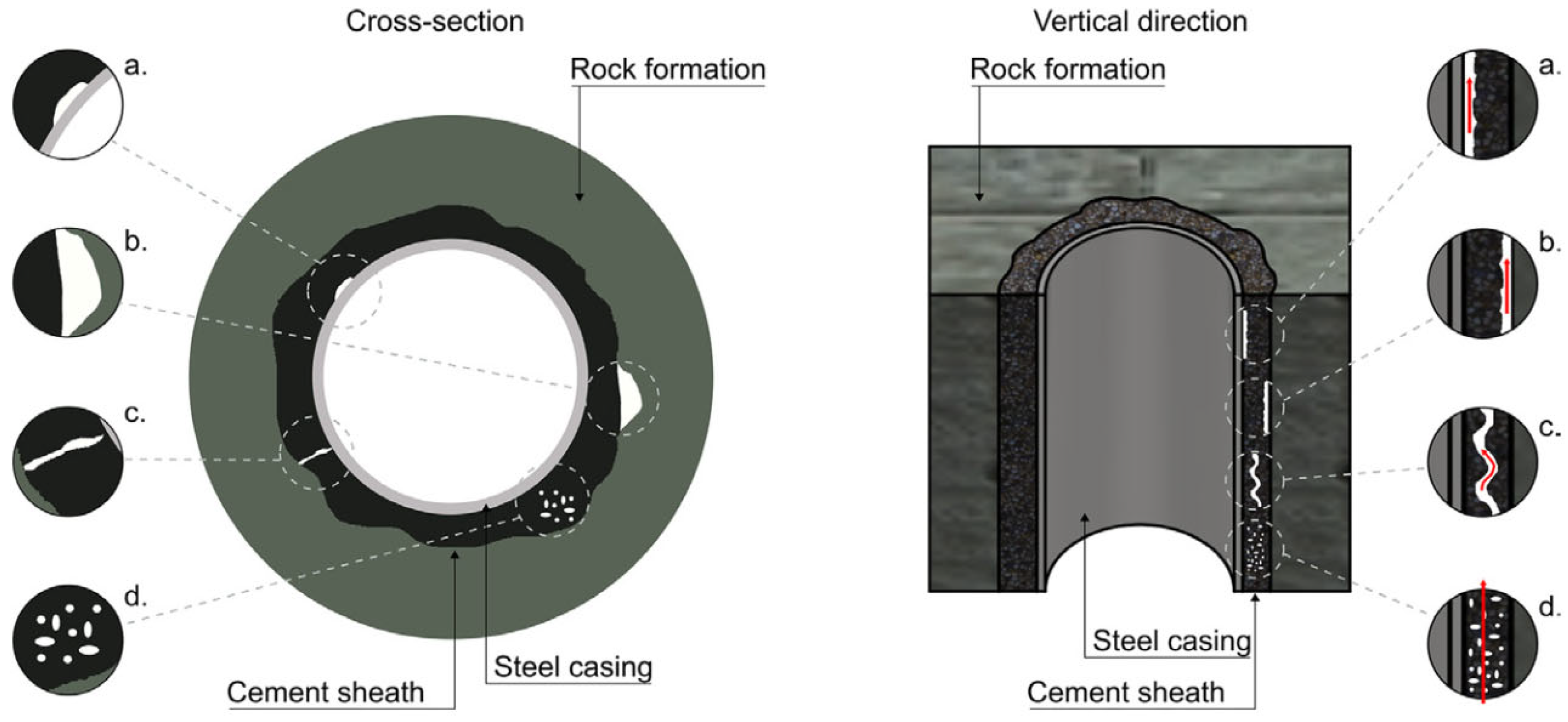
Figure 2.
Visualisation of CBL (left) and SBT log (right), from Bigelow [39].
Figure 2.
Visualisation of CBL (left) and SBT log (right), from Bigelow [39].
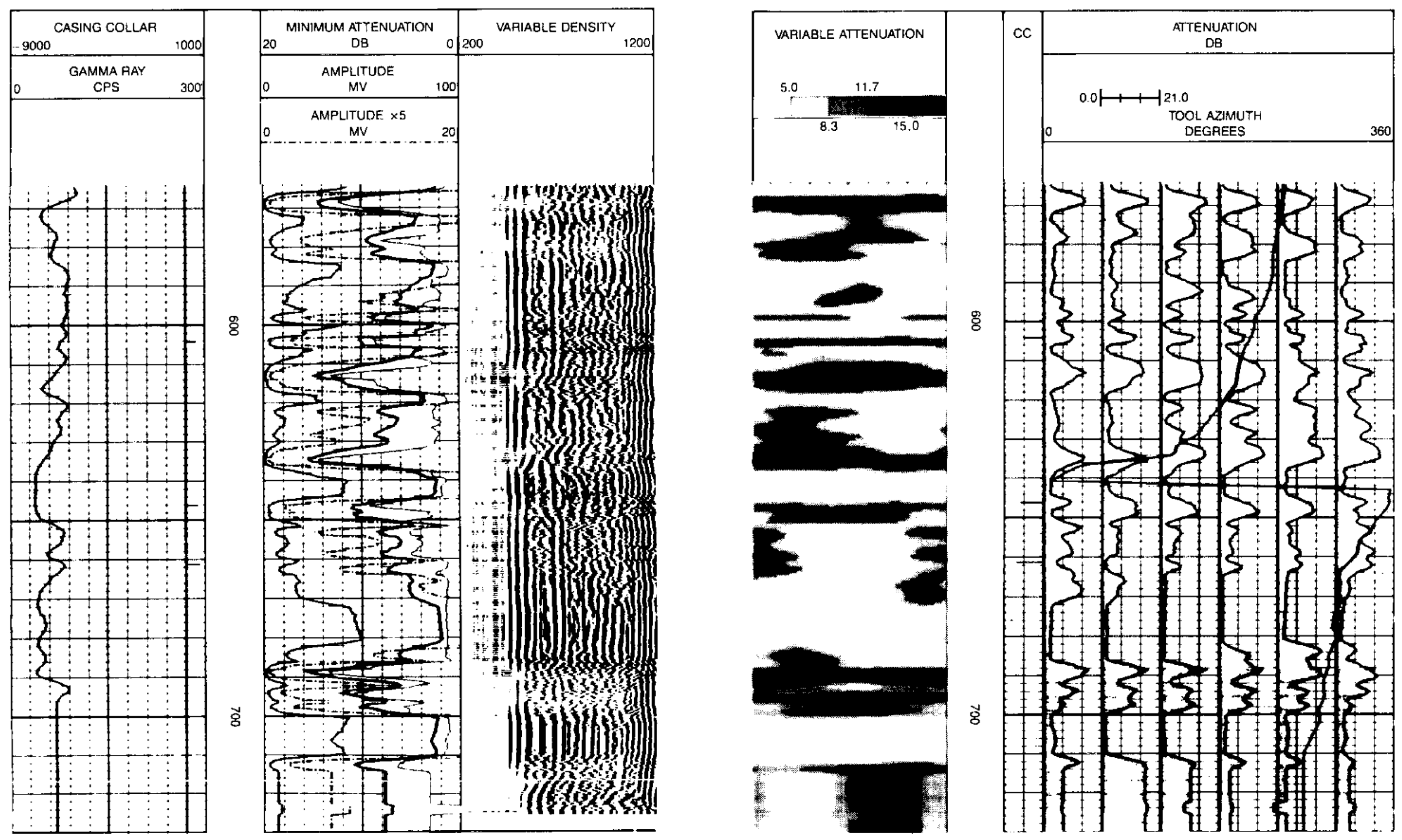
Figure 3.
Schematic of acoustic waveforms in cement bond log, from Fertl [50].
Figure 3.
Schematic of acoustic waveforms in cement bond log, from Fertl [50].
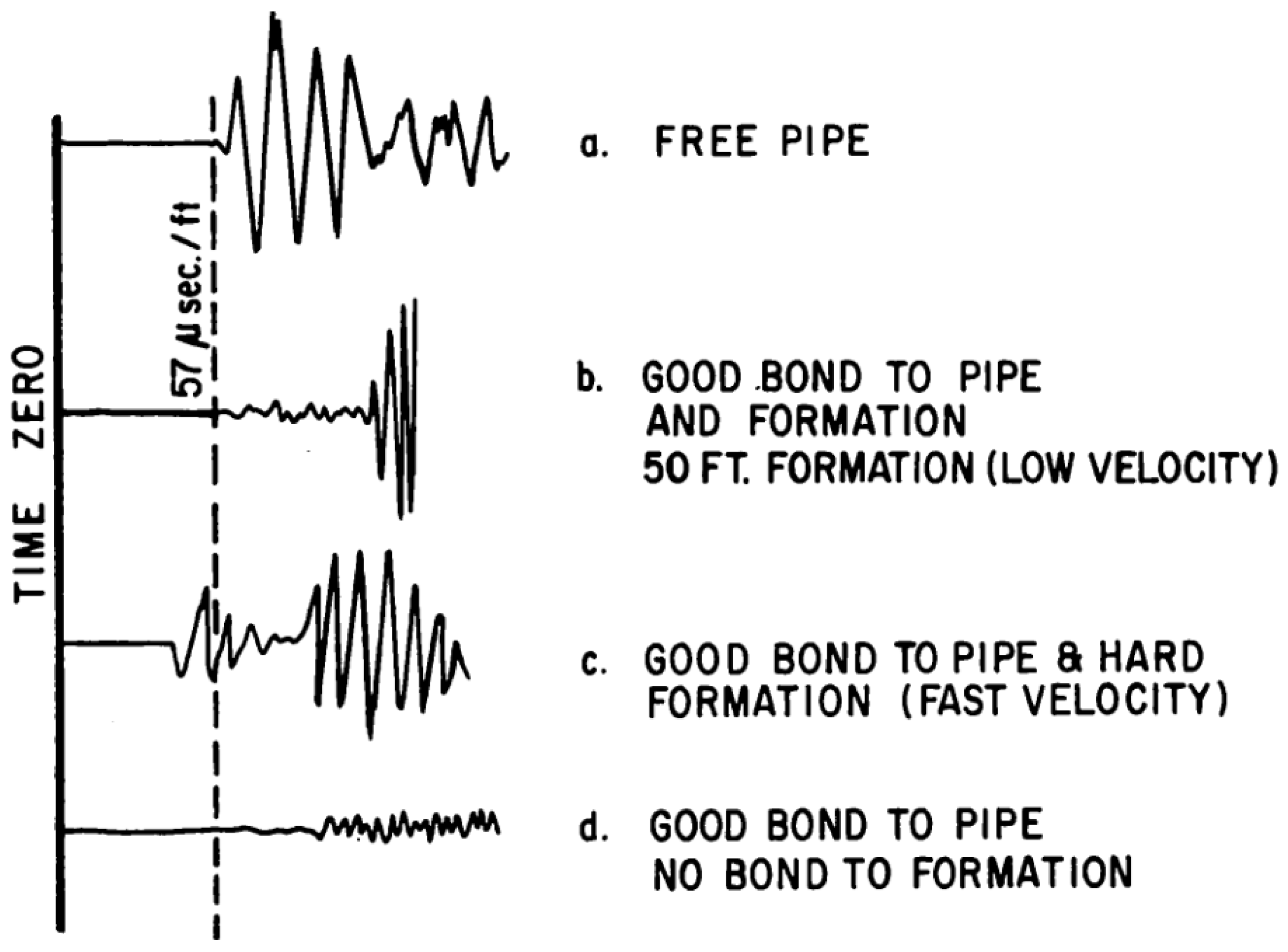
Figure 4.
Example of presentation from ultrasonic log data, from Thomas [40].
Figure 4.
Example of presentation from ultrasonic log data, from Thomas [40].
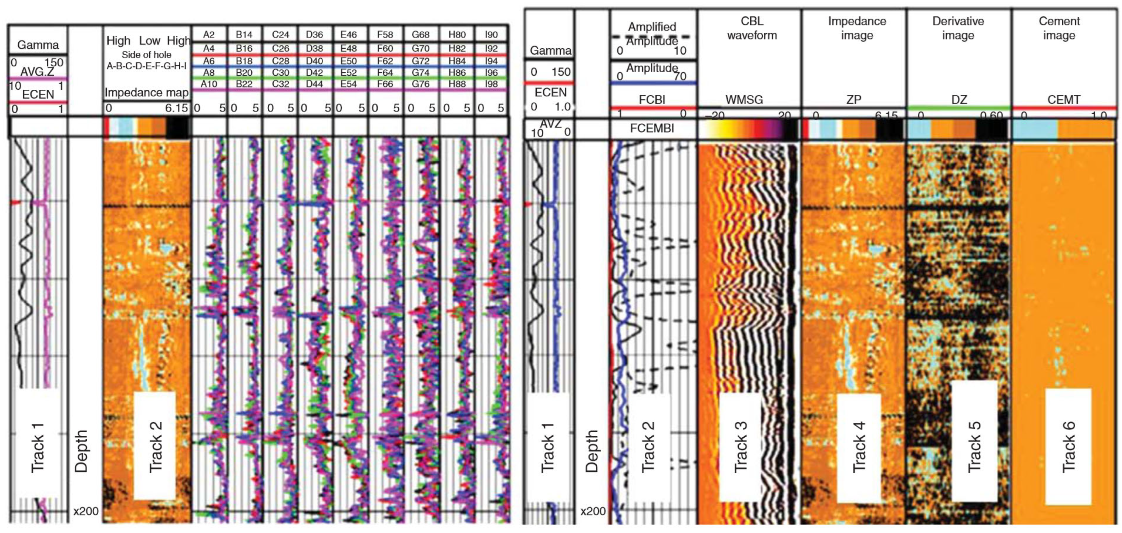
Figure 5.
Comparison of cement bond interpretation from machine learning and an expert. From Viggen [91].
Figure 5.
Comparison of cement bond interpretation from machine learning and an expert. From Viggen [91].
Disclaimer/Publisher’s Note: The statements, opinions and data contained in all publications are solely those of the individual author(s) and contributor(s) and not of MDPI and/or the editor(s). MDPI and/or the editor(s) disclaim responsibility for any injury to people or property resulting from any ideas, methods, instructions or products referred to in the content. |
© 2025 by the authors. Licensee MDPI, Basel, Switzerland. This article is an open access article distributed under the terms and conditions of the Creative Commons Attribution (CC BY) license (http://creativecommons.org/licenses/by/4.0/).
Copyright: This open access article is published under a Creative Commons CC BY 4.0 license, which permit the free download, distribution, and reuse, provided that the author and preprint are cited in any reuse.


