
Submitted:
09 July 2025
Posted:
11 July 2025
You are already at the latest version
Abstract
Vibrating feeders are used to empty bulk materials from storage bins, to feed and dispense materials into weighing bins or dispensers, or to feed materials evenly and smoothly into downstream equipment. The harmonic oscillation of the trough can be provided by an electromagnetic oscillator, which consists of an electromagnet consisting of a core and a coil with a given number of coil turns and armature. The aim of the paper has been to verify whether the working condition of the vibrating feeder, i.e. its fault-free operation and the ability to transport the required mass amount of material, can be described on a basis of the measured vibration values using acceleration sensors. The paper describes three experimental methods that allow with the use of force sensors to measure the adhesion force of the electromagnet and the deformation force of the bent leaf springs, and the use of acceleration sensors to measure the vibration on the trough and on the steel frame of the vibrating feeder. The highest average value of the effective vibration velocity (56.7 mm·s−1) in the horizontal plane was measured on a steel frame of a vibrating feeder using FR4 Epoxy leaf springs with a stiffness of 47.8 N·mm−1, with a weight of 2.57 kg of conveyed material per trough. The lowest average value of the effective vibration velocity (24.6 mm·s−1) has been measured at a weight of 5.099 kg of material conveyed on the trough. We can state that from the analysis of the measured vibration velocities transmitted to the steel frame of the vibrating feeders, it is possible to remotely monitor the partial phases of their operation, diagnose any faults that may occur, and also monitor whether the optimum amount of bulk material is loaded on the trough.
Keywords:
harmonic oscillation
; force sensor
; acceleration sensor
; electromagnetic exciter
; effective vibration velocity
1. Introduction
Vibrating feeders are short vibrating conveyors with the trough vibration provided by a harmonic vibration source, the so-called vibration exciter [1]. The vibration exciter is usually implemented as a forced drive by a crank mechanism [2,3]; as a drive by a mechanical exciter with unbalances [4,5,6] or as an electromagnetic drive [7,8].
The aim of the measurements carried out in this paper has been to verify the assumption whether the monitoring of vibrations (using vibrating sensors) transmitted to the supporting frame of a vibrating feeder can provide information about its operating characteristics.
The information, i.e. the electrical signals, detected by the vibration sensors can be used to diagnose the working operation of vibrating feeders in locations that may be in a considerable distance from where the vibrating feeder is installed. Such diagnostics of vibrating feeder parameters can provide controllers in the control centre with the information on whether the required amount of material is on the trough of the vibrating feeder, whether the vibrating feeder is in an optimal operating state or in a fault state.
P. Czubak et al. in their paper [9] analyse the influence of such parameters as the weight of the conveyed material and frequency on the reduction of vibration transmission to the bottom layer. They have come to the conclusion that the choice of optimal parameters, such as accurate calibration of spring stiffness, selection of materials with high absorption capacity and correct sizing of vibration elements, can significantly contribute to reducing vibration transmission to the substrate.
W. Surówka and P. Czubak in their paper [10] describe the operational behaviour of vibrating conveyors at resonance and its impact on the efficiency of material conveying.
Experimental tests have been carried out using two vibration sensors. One sensor has been installed on the trough of the vibrating feeder, the other on its supporting frame.
The vibrating feeder was equipped with an electromagnetic vibration exciter, the basic part of which consists of an electromagnet, which consists of an armature, a core and a coil with a given number of coil turns. An electromagnet [11] is coil with a core of magnetically soft steel used to create a temporary magnetic field. The principle consists in transforming energy of the electromagnetic field into the mechanical energy. The magnetic force [12] is generated when an electric current passes through the winding of a coil on a steel core, which attracts a movable part, called the armature. The magnetic flux of the electromagnet and the attractive force of the electromagnet depend directly on the magnitude of the electric current I [A] flowing through the coil, the number of coil turns Nc [–] and indirectly on the length δ [m] of the air gap between the core and the armature [13,14,15]. In practice, the attractive force is limited by the total magnetic conductivity of the electromagnet core and the magnetic flux dissipation [16].
The trough with a horizontally situated bottom (trough inclination angle β = 0 deg) was mechanically (by means of screw connections) attached to the end parts of four mounted pieces of leaf springs, each Ls = 88 mm, obliquely (at an angle α = 30 deg). The solenoid coil of the electromagnetic exciter has been powered from an amplitude/frequency controller (FQ1 DIG Process Controller) [17].
In the paper [18] V. Korendiy et al. present theoretical modelling and experimentally obtained data (defining the influence of design parameters on the operational stability and transport efficiency) for the assessment of dynamic properties of vibrating conveyors.
G. Cieplok in his paper [19] declares by numerical simulations the ability of easier control of undesired resonant vibrations by optimizing the geometry of the vibratory drive parameters.
The maximum attractive force Fmax [N] of the electromagnet [20,21,22] can be determined according to Eq. (1) assuming that the permeability of the vacuum μ0 [H·m–1] (μ0 = 1.257 [N·A–2]) is known, the magnetic induction in the air gap Bδ [T] and the cross-section of the contact area of the electromagnet core S [m2].
The cross-section S [m2] of the contact surface of the electromagnet core of the electromagnetic exciter of the vibratory feeder described in this paper is specified in Figure 1.
If the distance of the armature δ [m] from the electromagnet core, the number of coil turns Nc [‒] and the current I [A] flowing through the electromagnet coil, the permeability of the vacuum μ0 [H·m–1], the contact surface of the electromagnet core S [m2] are known, it is possible to express the attractive force Fh [N] of the electromagnet by the relation (2).
The property of a coil is characterized by its inductance L [H]. The inductance is a physical quantity expressing the ability of an electrically conducting body flowing with an electric current to generate a magnetic field in its surroundings. A coil with a larger inductance acts in an AC circuit in such a way that it generates higher resistance to the current. This is due to the fact that the coil induces a voltage directed by its own induction against the voltage of the source. A magnetic field periodically appears and disappears in the coil, so there is no heating of the coil. The action of the coil on the alternating current is characterized by the quantity of inductive reactance (inductance XL [Ω].
Since the voltage induced in the coil also depends on the rate, at which the alternating current changes, it is obvious that the inductance also depends on the frequency of the alternating current. The greater the frequency of the AC current, the greater the inductance of the coil. The coil of inductance L [H] has inductance XL [Ω], in an AC circuit, for which the relation (1) applies.
With AC single-phase electromagnets [23,24] the current is determined by the resistance and self-inductance of the coil, which depends on the position of the armature. If the resistance of the coil is negligible with respect to its reactance, the magnetic flux will be constant and the electromagnet will induce a constant pull at any position of the armature. Resistance, which cannot be neglected, will manifest itself by altering this ideal tensile characteristic. In the initial position, when the air gap is large, the coil impedance is low and the coil draws a high current. The voltage drop induced on the coil resistance will cause the voltage drop across the reactance generates a significantly weaker magnetic flux [25]. Therefore, the initial thrust will be relatively small. If the air gap decreases, the reactance of the coil increases, the current and voltage drop across the coil resistance decreases, the voltage across the reactance increases, and therefore the thrust increases because the magnetic flux corresponding to the voltage across the reactance gradually increases.
In electromagnetic exciters, the effect of the excitation force is induced by the dynamic force generated during the straight-line reciprocating uniform motion of the metal armature of the electromagnet [26]. The armature of the electromagnet is firmly connected to the trough. The core of the solenoid is connected to the exciter body via pre-tensioned springs.
If the exciter is supplied with AC current at a frequency of 50 Hz, the trough oscillates at a frequency of 100 Hz. If we include a frequency rectifier in the circuit, the oscillation of the exciter is reduced by half and oscillates only at 50 Hz frequency [27].
A simple harmonic motion [28] is the typical motion of a mass on a spring when subjected to a linear elastic reciprocating force given by Hooke's law. The motion is sinusoidal in time and exhibits a single resonant frequency [29].
A mass oscillating by harmonic motion has one resonant frequency determined by its spring constant sc [N·m–1] and mass m2 [kg]. Using the Hooke's law, neglecting damping and the mass of the spring, the Newton's second law produces the equation of motion (4).
The solution of differential equation (4) has the form (5).
where "B" is the integration constant. By substituting the equation (5) into equation (4 ), we obtain (6).
The integration constant "B" can be expressed from the assumption, see Figure 2, saying that if then . By substituting this consideration into the equation (6 ), we obtain (7).
The constant "B" (7) defines the elongation y(t) [m] (8) of the leaf spring of stiffness sc [N·m–1] due to the mass m2 [kg]. The harmonic oscillation of a trough mounted on springs of total stiffness sc [N·m‒1] is caused by the force F(t) [N] (8), the magnitude of which is directly proportional to the deflection y(t) [m] and is oriented towards the equilibrium position at each instant.
S. Ogonowski and P. Krauze describe in [30] how the dynamic properties of magnetorheological dampers and the motion trajectory of vibration devices can be influenced by the magnetic field control.
The authors M. Pesík and P. Němeček in their paper [31] analyse various types of vibration isolation elements (such as rubber dampers, spring systems and viscous dampers) and evaluate their effectiveness (reduction of vibration transmission to the structural frame and bottom layer) in various operating conditions of vibrating conveyors.
2. Materials and Methods
Subsections 2.1 to 2.3 of this chapter describe three laboratory devices that were created to experimentally determine the actual size:
- -
- the holding force Fh [N] of the electromagnet depending on the distance δ [m] of the armature from the core of the electromagnet,
- -
- stiffness scj [N·m‒1] of leaf spring made of material (FR4 Epoxy, steel, plastic PCCF),
- -
- effective trough vibration velocity and effective frame vibration velocity v∗(l,i,j)k,m [mm·s‒1],
which are used in a laboratory vibrating conveyor, the trough oscillation of which is induced by the electromagnetic exciter (see Figure 1).
2.1. Laboratory Device for Detecting the Magnitude of the Adhesive Force of an Electromagnet
The structural design of the experimental device, see Figure 3, was designed at the (Department of Machine and Industrial Design, Faculty of Mechanical Engineering, VSB-Technical University of Ostrava in the SolidWorks® software environment Premium 2012×64 SP5.0.
The experimental device consists of a frame 4, to the lower part of which the electromagnet 1 is attached by means of screw connections. The armature of the electromagnet 2 is mechanically connected to the force transducer 3 (type MCF30-500 [32]), which is attached to the supporting frame 4. The force attracting the armature of electromagnet 2 (with the parallel lower surface and being 2 mm (or 4 mm) away from the upper surface of the electromagnet) to the electromagnet 1 was detected by force sensor 3, the signal of the measured quantity of the tensile force was displayed in the DEWESoft X2 SP5 software environment [33], which was recorded by the DEWESoft DS-NET measuring apparatus [34], see Figure 4.
2.2. Laboratory Device Designed to Determine the Stiffness of a Leaf Spring
The stiffness of the leaf spring sc [N·m–1] can be analytically calculated according to relation (9), provided that the modulus of elasticity Es [Pa] of the material, of which the spring is made and the moment of inertia Ix [m4] are known.
The stiffness of the leaf spring (constant of proportionality) scj [N·mm–1] (j = 1 až 10 − number of the leaf spring), see Figure 5, used for the vibrating conveyor, is defined as the ratio of the force FMijk [N] and the vertical displacement yMijk [mm] of the end portion of the bent spring, which is induced by the force FMj [N].
The stiffness of 10 pieces of leaf springs scj [N·mm‒1]; 4 pieces made of FR4 Epoxy (j = 1 to 4), 2 pieces made of steel (j = 5 to 6) and the remaining 4 pieces (j = 7 to 10) have been produced using the FDM 3D printing technology from PCCF filament (Prusament PC Blend Carbon Fiber [35], fill density 15%) printed on a 3D printer (type Pruša MK4S); was experimentally determined from measured values of yMk [mm] a FMijk [N] on the laboratory device, see Figure 6. The laboratory device consists of a steel frame 1, to which two positioning tables (linear unit type PT7312-PA) [36] are attached by means of screw connections. A strain gauge load cell 3 (type MCF30-500) is attached to the vertical linear unit 2. The horizontal linear unit 4 with the attached leaf spring 5.
As a result of the rotation of the hand grip of the vertical linear unit 2, the force transducer 3 at a certain moment comes into contact with the end of the leaf spring 5. Further rotation of the hand handle of the vertical linear unit 2 causes the leaf spring 5 to bend, which can be considered as a unilaterally fixed beam in terms of elasticity and strength (see Figure 6(c)).
A strain gauge force transducer cable (type MCF30-500), terminated with a D-Sub 9-pin plug, has been connected to the DS NET BR4 module [37]. Connectors RJ45 of the network cable are used to connect the module DS GATE [37] to PC (ASUS K72JR-TY131), in which the software DEWESoft X2 SP5 is installed. In the DEWESoft X2 SP5 software environment, the signals of the measured quantity (compressive force FMijk [N]) were recorded and detected by the DEWESoft DS-NET measuring apparatus [37], see Figure 6(d).
2.3. Laboratory Model of Vibrating Feeder
Measurement of the effective vibration velocity values v∗(l,i,j)k,m [mm·s–1] (where ∗ ‒ leaf spring material, l = x, y, z ‒ axes of the coordinate system, i ‒ acceleration sensor number, j ‒ number of measurements, k ‒ amplitude value set on the FQ1 DIGcontroller , m ‒ weight of material on the trough), was carried out on a laboratory model of the vibrating feeder, see Figure 7. The oscillation velocity is used at low and medium frequencies (10 Hz ‒ 1000 Hz) to identify faults manifested at these frequencies.
The oscillating motion of trough 1 (its own weight mz = 3.37 kg) is generated by an electromagnetic oscillator, see Figure 7(a), which consists of electromagnet 4 (type ME 32/31 K03Z) and the armature 5. The trough 1 is mechanically attached to one end of the leaf springs 3 of rectangular cross-section and to the armature of the electromagnet 5. The second end portion of the leaf springs 3 is attached to the steel frame 2 of the vibrating feeder.
The solenoid coil 4 was supplied with current from the amplitude/frequency controller 6 (FQ1 DIG Process Controller [17]), see Figure 7(b). The digital control of the linear feeder using the FQ1 DIG Process Controller 6 allows the optimization of the vibrating feeder operation by finding its resonant frequency (maximum output), thus eliminating its lengthy and difficult mechanical calibration.
Effective vibration velocity values v∗(l,i,j)k,m [mm·s‒1] of the vibrating trough 1 and steel frame 2 of the vibrating feeder, see Figure 8(a), were detected by two acceleration sensors 3 (type PCE KS903.10 [38]).
During the experimental vibration measurements on the vibrating feeder model the signals from the acceleration sensors 3 were recorded by the DEWESsoft SIRIUSi‒HS 6×ACC, 2×ACC+ 5 measuring apparatus [39], see Figure 8(b). The time records of the measured values have been transformed by the measuring apparatus into effective values of the broadband velocity. The effective velocity values v∗(l,i,j)k,m [mm·s‒1] of the periodic waveform were displayed on a PC 6 monitor in the DEWESoft X measurement software environment.
The measurement chain, see Figure 8(c), presents a sequence of interconnected instruments and devices allowing to detect and process the measured vibration signals of the trough 1 and steel frame 2 of a laboratory model of a vibrating feeder with an electromagnetic vibration exciter.
3. Results
3.1. Measurement of Electromagnet Holding Force Values

Table 1.
Measured size of the holding force Fh [N] of the electromagnet, at frequency f = 50 Hz, armature distance δ [m] and amplitude A [m].
Table 1.
Measured size of the holding force Fh [N] of the electromagnet, at frequency f = 50 Hz, armature distance δ [m] and amplitude A [m].
| δ [mm] | A [m] | F0 [N] | FM [N] | Fh = F0 +?FM? [N] | δ [mm] | A [m] | F0 [N] | FM [N] | Fh = F0 +?FM? [N] |
| 2 | 10% | 18.2 | – 44.7 | 62.9 | 4 | 20% | 16.6 | – 17.7 | 34.3 |
| 20% 1 | 18.3 | – 44.6 | 62.9 | 40% 3 | 16.6 | – 17.3 | 33.9 | ||
| 30% | 18.4 | – 44.8 | 63.2 | 60% | 16.6 | – 17.4 | 34.0 | ||
| 40% | 18.3 | – 44.5 | 62.8 | 80% | 16.6 | – 17.3 | 33.9 | ||
| 50% 2 | 18.2 | – 44.8 | 63.0 | 99% 4 | 16.6 | – 17.2 | 33.8 |
Figure 9.
Measured magnitude of the thrust force Fh [N] of the electromagnet. Frequency f = 50 Hz, amplitude A [m] (a) 20%, (b) 50%. Armature clearance δ = 2 mm.
Figure 9.
Measured magnitude of the thrust force Fh [N] of the electromagnet. Frequency f = 50 Hz, amplitude A [m] (a) 20%, (b) 50%. Armature clearance δ = 2 mm.
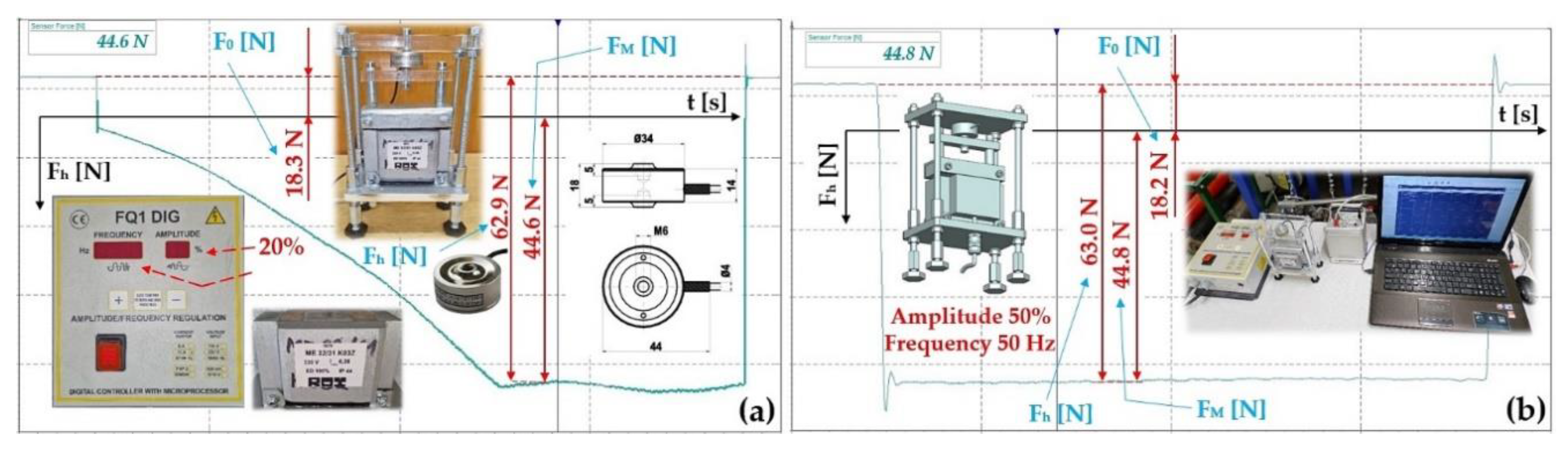
Figure 10.
Measured magnitude of the thrust force Fh [N] of the electromagnet. Frequency f = 50 Hz, amplitude A [m] (a) 40%, (b) 99%. Armature clearance δ = 4 mm.
Figure 10.
Measured magnitude of the thrust force Fh [N] of the electromagnet. Frequency f = 50 Hz, amplitude A [m] (a) 40%, (b) 99%. Armature clearance δ = 4 mm.
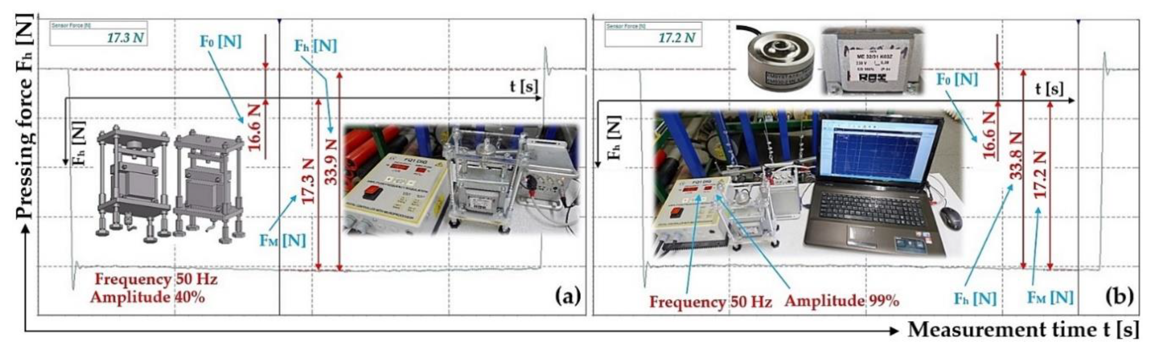
Figure 11.
Measured values of the compressive force (a) FM11k [N], (b) FM21k [N], which produces the deflection yMK [mm] of the end part of the leaf spring No. 1, made of FR4 Epoxy.
Figure 11.
Measured values of the compressive force (a) FM11k [N], (b) FM21k [N], which produces the deflection yMK [mm] of the end part of the leaf spring No. 1, made of FR4 Epoxy.
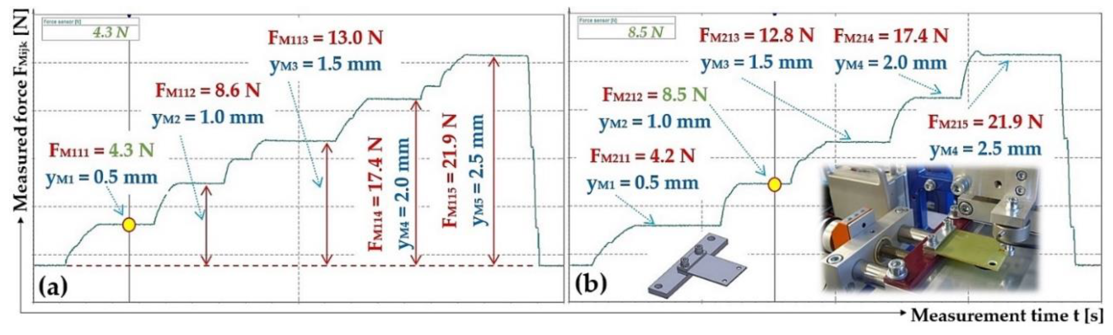
Figure 12.
Measured values of the compressive force (a) FM22k [N], (b) FM32k [N], which produces the deflection yMK [mm] of the end part of the leaf spring No. 2, made of FR4 Epoxy.
Figure 12.
Measured values of the compressive force (a) FM22k [N], (b) FM32k [N], which produces the deflection yMK [mm] of the end part of the leaf spring No. 2, made of FR4 Epoxy.
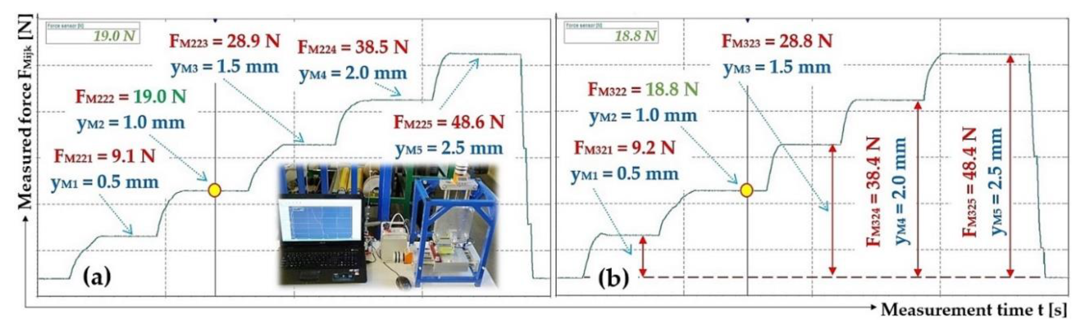
Figure 13.
Measured values of the compressive force (a) FM35k [N], (b) FM16k [N], which produces the deflection yMK [mm] of the end part of the leaf spring No. 5 and No. 6, made of Steel.
Figure 13.
Measured values of the compressive force (a) FM35k [N], (b) FM16k [N], which produces the deflection yMK [mm] of the end part of the leaf spring No. 5 and No. 6, made of Steel.
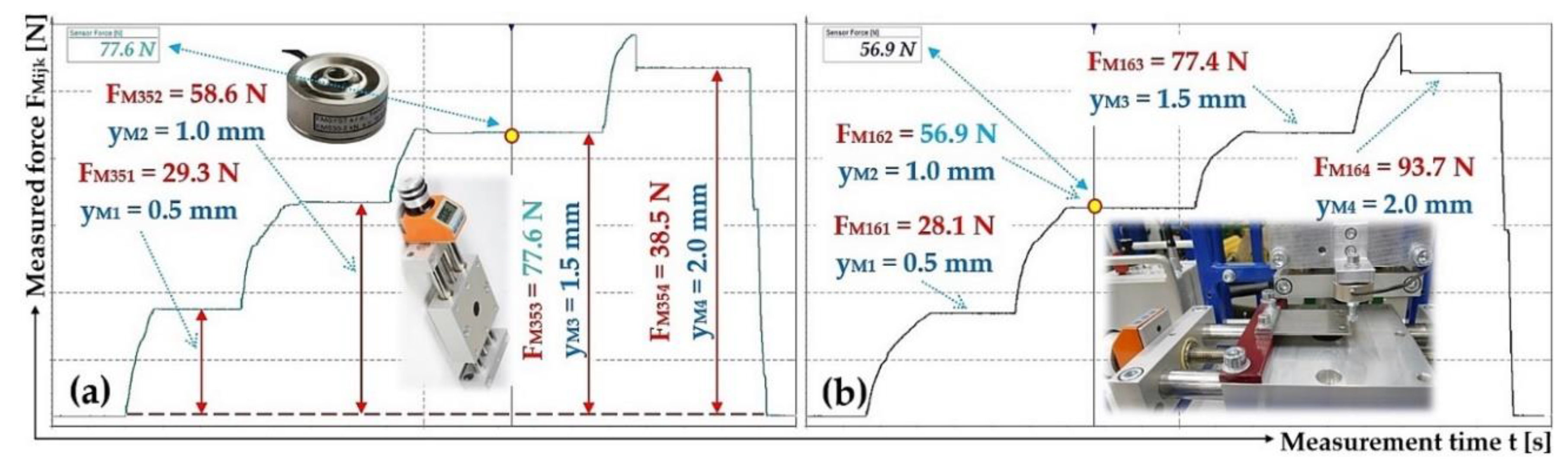
Figure 14.
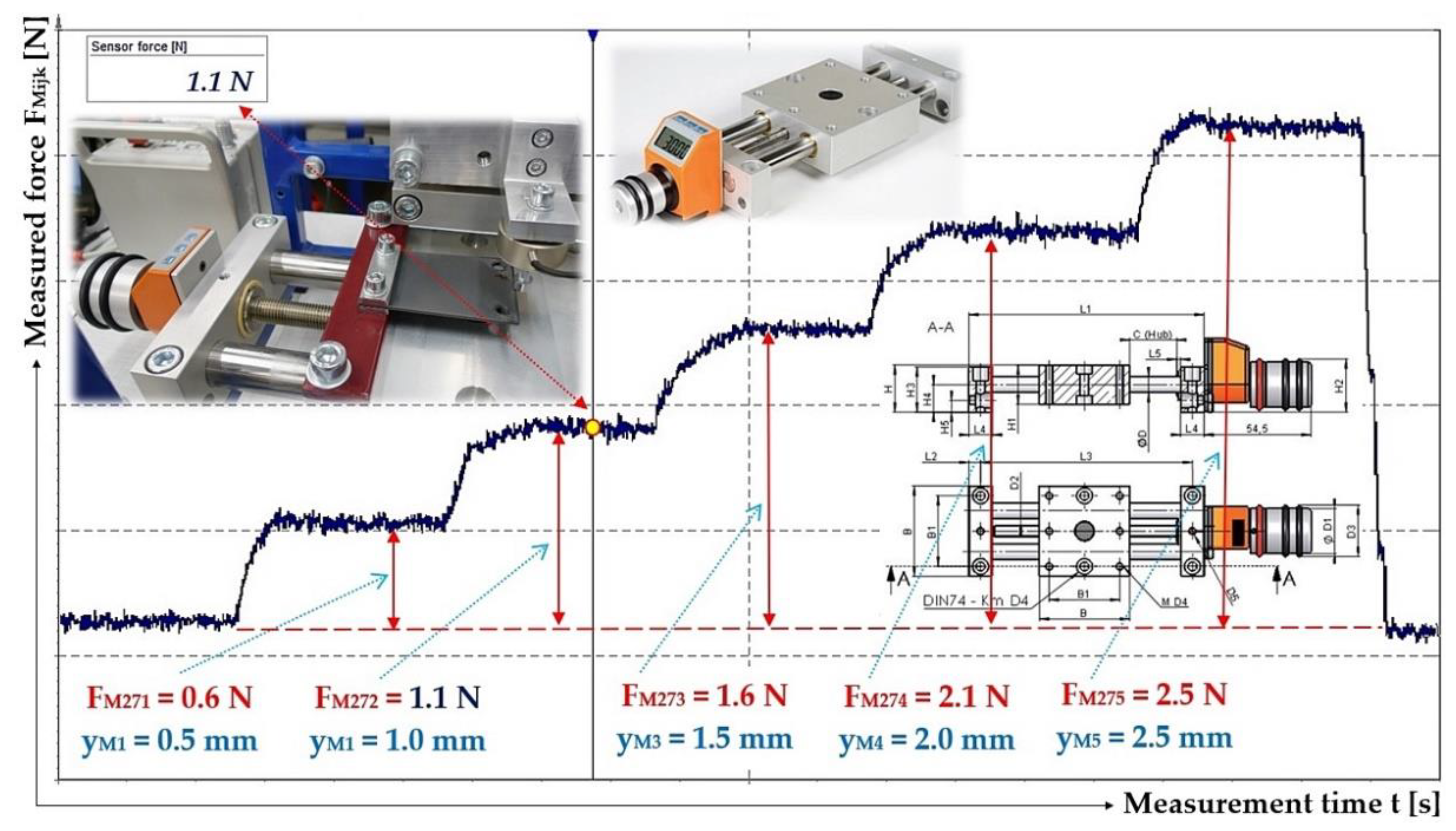
Measured values of the compressive force FM1jk [N], which produces the deflection yMK [mm] of the end part of the leaf spring No. 7 to No. 10, made of Plastic PCCF.
Figure 14.
Measured values of the compressive force FM1jk [N], which produces the deflection yMK [mm] of the end part of the leaf spring No. 7 to No. 10, made of Plastic PCCF.
3.2. Measurement of the Leaf Spring Deflection
The deflection values yMK [mm] of the end section (determined on laboratorydevice, see Figure 8) of all 10 pieces of leaf springs 5 are read on the digital display (located at the top) of the vertical linear unit 2. The values of yMK [mm] are recorded in the Table 2 (and the following tables in this Chapter 2.2).
The deflection yMK [mm] of the end part of the leaf spring 5 is induced by the compressive force (of the vertically moving sliding part of the linear unit 2), the actual magnitude of which FMijk [N] is measured by the force sensor 3 (type MCF30-500) and recorded in Table 2 (and the following tables in this chapter). From the measured values of the compressive force FMijk [N] and the deflection yMK [mm], the stiffness scijk [N·mm‒1] of a particular (j = 1 to 10) leaf spring is calculated by their ratio.
Table 2.
Stiffness of leaf spring No. 1 (j = 1). Thickness ts = 1.9 mm, material ‒ FR4 Epoxy.
| k | j = 1 | ||||||
| i | 1 | 2 | 3 | ||||
| yMk [mm] | FMijk [N] 1 | scijk [N·mm‒1] | FMijk [N] 2 | scijk [N·mm‒1] | FMijk [N] | scijk [N·mm‒1] | |
| 0 | 0 | 0 | 0 | 0 | 0 | 0 | 0 |
| 1 | 0.5 | 4.3 | 8.6 | 4.2 | 8.4 | 4.2 | 8.4 |
| 2 | 1 | 8.6 | 8.6 | 8.5 | 8.5 | 8.4 | 8.4 |
| 3 | 1.5 | 13.0 | 8.7 | 12.8 | 8.5 | 12.8 | 8.5 |
| 4 | 2 | 17.4 | 8.7 | 17.4 | 8.7 | 17.3 | 8.7 |
| 5 | 2.5 | 21.9 | 8.8 | 21.9 | 8.8 | 21.9 | 8.8 |
| 8.7 | 8.6 | 8.5 | |||||
| 8.6 | |||||||
| 0.2 | |||||||
| 8.6 ± 0.2 | |||||||
From i = 3 repeated measurements under the same conditions, the values of compressive forces FMijk [N] and deflection values yMk [mm] have been measured. In the table of critical values of the Student distribution [40], for the chosen risk α = 5%, the Student’s factor tα,i = 4.3 [40], has been found. According to [40], the standard deviation of the arithmetic mean so [N·mm‒1] was calculated for i = 3 repeated measurements. The cardinal error κα,i [N·mm‒1], see the penultimate last row of Table 2 and subsequent tables in this chapter, is calculated as the product tα,i·so.
Table 3.
Stiffness of leaf spring No. 2 (j = 2). Thickness ts = 2.3 mm, material ‒ FR4 Epoxy.
| k | j = 2 | ||||||
| i | 1 | 2 | 3 | ||||
| yMk [mm] | FMijk [N] | scijk [N·mm‒1] | FMijk [N] 1 | scijk [N·mm‒1] | FMijk [N] 2 | scijk [N·mm‒1] | |
| 0 | 0 | 0 | 0 | 0 | 0 | 0 | 0 |
| 1 | 0.5 | 9.5 | 19.0 | 9.1 | 18.2 | 9.2 | 18.4 |
| 2 | 1 | 19.5 | 19.5 | 19.0 | 19.0 | 18.8 | 18.8 |
| 3 | 1.5 | 29.1 | 19.4 | 28.9 | 19.3 | 28.8 | 19.2 |
| 4 | 2 | 38.7 | 19.4 | 38.5 | 19.3 | 38.4 | 19.2 |
| 5 | 2.5 | 48.5 | 19.4 | 48.6 | 19.4 | 48.4 | 19.4 |
| 19.3 | 19.0 | 19.0 | |||||
| 19.1 | |||||||
| 0.3 | |||||||
| 19.1 ± 0.3 | |||||||
Table 4.
Stiffness of leaf spring No. 3 (j = 3). Thickness ts = 1.9 mm, material ‒ FR4 Epoxy.
| k | j = 3 | ||||||
| i | 1 | 2 | 3 | ||||
| yMk [mm] | FMijk [N] | scijk [N·mm‒1] | FMijk [N] | scijk [N·mm‒1] | FMijk [N] | scijk [N·mm‒1] | |
| 0 | 0 | 0 | 0 | 0 | 0 | 0 | 0 |
| 1 | 0.5 | 3.2 | 6.4 | 3.1 | 6.2 | 3.1 | 6.2 |
| 2 | 1 | 6.5 | 6.5 | 6.4 | 6.4 | 6.4 | 6.4 |
| 3 | 1.5 | 9.7 | 6.5 | 9.7 | 6.5 | 9.7 | 6.5 |
| 4 | 2 | 13.0 | 6.5 | 13.0 | 6.5 | 13.1 | 6.6 |
| 5 | 2.5 | 16.4 | 6.6 | 16.5 | 6.6 | 16.5 | 6.6 |
| 6.5 | 6.4 | 6.4 | |||||
| 6.4 | |||||||
| 0.1.3 | |||||||
| 6.4 ± 0.1 | |||||||
Table 5.
Stiffness of leaf spring No. 4 (j = 4). Thickness ts = 2.3 mm, material ‒ FR4 Epoxy.
| k | j = 4 | ||||||
| i | 1 | 2 | 3 | ||||
| yMk [mm] | FMijk [N] | scijk [N·mm‒1] | FMijk [N] | scijk [N·mm‒1] | FMijk [N] | scijk [N·mm‒1] | |
| 0 | 0 | 0 | 0 | 0 | 0 | 0 | 0 |
| 1 | 0.5 | 6.8 | 13.6 | 6.5 | 13.0 | 6.5 | 13.0 |
| 2 | 1 | 13.9 | 13.9 | 13.6 | 13.6 | 13.6 | 13.6 |
| 3 | 1.5 | 20.8 | 13.9 | 20.7 | 13.8 | 20.7 | 13.8 |
| 4 | 2 | 27.9 | 14.0 | 27.7 | 13.9 | 27.7 | 13.9 |
| 5 | 2.5 | 34.9 | 14.0 | 34.8 | 13.9 | 35.0 | 14.0 |
| 13.9 | 13.6 | 13.7 | |||||
| 13.7 | |||||||
| 0.3 | |||||||
| 13.7 ± 0.3 | |||||||
Table 6.
Stiffness of leaf spring No. 5 (j = 5). Thickness ts = 2.0 mm, material ‒ Steel.
| k | j = 5 | ||||||
| i | 1 | 2 | 3 | ||||
| yMk [mm] | FMijk [N] | scijk [N·mm‒1] | FMijk [N] | scijk [N·mm‒1] | FMijk [N] 1 | scijk [N·mm‒1] | |
| 0 | 0 | 0 | 0 | 0 | 0 | 0 | 0 |
| 1 | 0.5 | 29.9 | 59.8 | 29 | 58.0 | 29.3 | 58.6 |
| 2 | 1 | 57.4 | 57.4 | 57.6 | 57.6 | 58.6 | 58.6 |
| 3 | 1.5 | 76.7 | 51.1 | 77.5 | 51.7 | 77.6 | 51.7 |
| 4 | 2 | 98.1 | 49.1 | 97.4 | 48.7 | 95.3 | 47.7 |
| 54.3 | 54.0 | 54.1 | |||||
| 54.1 | |||||||
| 0.3 | |||||||
| 54.1 ± 0.3 | |||||||
1 see Figure 13(a).
Table 7.
Stiffness of leaf spring No. 6 (j = 6). Thickness ts = 2.0 mm, material ‒ Steel.
| k | j = 6 | ||||||
| i | 1 | 2 | 3 | ||||
| yMk [mm] | FMijk [N] 1 | scijk [N·mm‒1] | FMijk [N] | scijk [N·mm‒1] | FMijk [N] | scijk [N·mm‒1] | |
| 0 | 0 | 0 | 0 | 0 | 0 | 0 | 0 |
| 1 | 0.5 | 28.1 | 56.9 | 28.0 | 56.0 | 28.5 | 57.0 |
| 2 | 1 | 56.9 | 51.6 | 57.1 | 57.1 | 57.0 | 57.0 |
| 3 | 1.5 | 77.4 | 46.9 | 76.5 | 51.0 | 77.2 | 51.5 |
| 4 | 2 | 93.7 | 56.2 | 92.9 | 46.5 | 96.1 | 48.1 |
| 52.9 | 52.6 | 53.4 | |||||
| 53.0 | |||||||
| 0.7 | |||||||
| 53.0 ± 0.7 | |||||||
1 see Figure 13(b).
Table 8.
Stiffness of leaf spring No. 7 to No. 10 (j = 7 to 10). Thickness ts = 2.0 mm, material ‒ Plastic PCCF.
Table 8.
Stiffness of leaf spring No. 7 to No. 10 (j = 7 to 10). Thickness ts = 2.0 mm, material ‒ Plastic PCCF.
| k | j = 7 až 10 | ||||||
| i | 1 | 2 | 3 | ||||
| yMk [mm] | FMijk [N] 1 | scijk [N·mm‒1] | FMijk [N] | scijk [N·mm‒1] | FMijk [N] | scijk [N·mm‒1] | |
| 0 | 0 | 0 | 0 | 0 | 0 | 0 | 0 |
| 1 | 0.5 | 0.6 | 1.2 | 0.6 | 1.2 | 0.6 | 1.2 |
| 2 | 1 | 1.1 | 1.1 | 1.1 | 1.1 | 1.1 | 1.1 |
| 3 | 1.5 | 1.6 | 1.1 | 1.6 | 1.1 | 1.6 | 1.1 |
| 4 | 2 | 2.1 | 1.1 | 2.1 | 1.1 | 2.1 | 1.1 |
| 5 | 2.5 | 2.5 | 1.1 | 2.7 | 1.1 | 2.7 | 1.1 |
| 1.1 | 1.1 | 1.1 | |||||
| 1.1 | |||||||
| 0.0 | |||||||
| 1.1 ± 0.0 | |||||||
1 see Figure 14.
3.3. Laboratory Device for Determining the Effective Value of the Vibration Velocity
The measurements of the effective vibration velocity values vc(l,1,j)k,0 [mm·s–1] of the trough (i = 1, see Table 9) and steel frame (i = 2, see Table 9) of the vibrating feeder and the electromagnetic vibration exciter were repeated three times (j = 1 to 3) for each material type (∗ = c ‒ FR4 Epoxy, s ‒ steel, p ‒ plastic PCCF) from which the leaf springs have been made and set the value k [%] (k = % magnitude of amplitude A [mm]) on the amplitude/frequency controller FQ1 DIG [17]. Effective values of the vibration velocity v∗(l,i,j)k,m [mm·s‒1] of the trough vibration were sensed by two acceleration sensors (PCE KS903.10) and a measuring apparatus (DEWESsoft SIRIUSi‒HS 6×ACC, 2×ACC+ [39,41]) in three mutually perpendicular planes (∗ = x, y, z ‒ axes of the coordinate system). The measurements were performed in the absence of material on the trough mq = 0 kg, when the electromagnetic exciter only oscillated the trough self-mass mz = 3.37 kg, and at the mass of material on the trough mq = 2.57 kg and 5.099 kg.
Figure 15 indicates the graphical progression (j = 1, see Table 9) of the measured values of the effective vibration velocities vc(l,i,j)k,m [mm·s–1] in three mutually perpendicular planes (l = x, y, z) on the trough and on the steel frame of the vibrating feeder, when the trough is supported by four pieces of leaf springs (material FR4 Epoxy, ∗ = c). Amplitude of the trough oscillation A = k· A [mm] (k = 10%), frequency of the trough oscillation f = 50 Hz, mass of the material to be conveyed m = 0 kg.
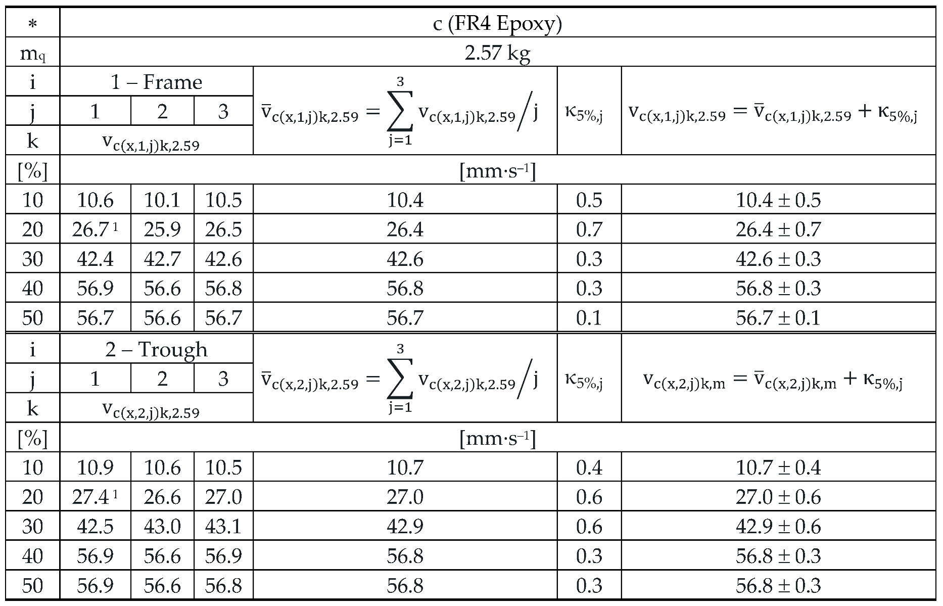
The 3 times repeated measurements of the effective values of the vibration velocity vc(x,i,j)k,2.59 [mm·s–1] of the vibration of the trough (i = 1) and the steel frame (i = 2) of the vibrating feeder with electromagnetic vibration exciter, the trough of which was loaded with the mass of material m = 2.59 kg is supported by leaf springs made of material c ‒ FR4 Epoxy, are specified in Table 10.
Figure 16 indicates the graphical progression (j = 1, see Table 10) of the measured values of the effective vibration velocities vc(l,i,j)k,2.57 [mm·s‒1] in the direction of “x” axis (l = x) on the trough and on the steel frame of the vibrating feeder, when the trough is supported by four pieces of leaf springs (material FR4 Epoxy, ∗ = c). Amplitude of the trough oscillation A = k· A [mm] (k = 20%), frequency of the trough oscillation f = 50 Hz, mass of the material to be conveyed m = 2.57 kg.
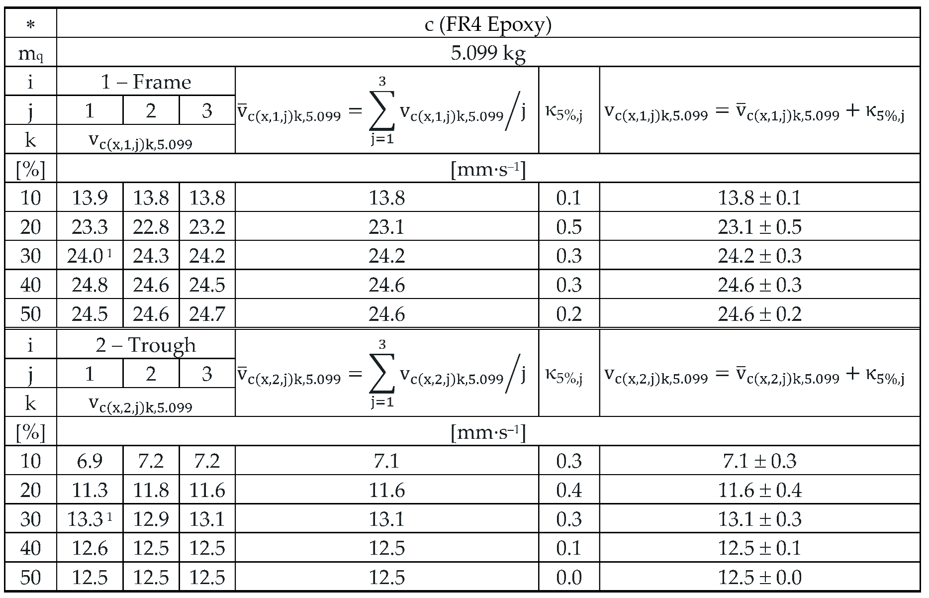
The 3 times repeated measurements of the effective values of the vibration velocity vc(x,i,j)k,5.099 [mm·s‒1] of the vibration of the trough (i = 1) and the steel frame (i = 2) of the vibrating feeder with electromagnetic vibration exciter, the trough of which was loaded with the mass of material m = 5.099 kg is supported by leaf springs made of material c ‒ FR4 Epoxy, are specified in Table 11.
Figure 17 indicates the graphical progression (j = 1, see Table 10) of the measured values of the effective vibration velocities vc(l,i,j)k,5.099 [mm·s‒1] in the direction of “x” axis (l = x) on the trough and on the steel frame of the vibrating feeder, when the trough is supported by four pieces of leaf springs (material FR4 Epoxy, ∗ = c). Amplitude of the trough oscillation A = k· A [mm] (k = 30%), frequency of the trough oscillation f = 50 Hz, mass of the material to be conveyed m = 5.099 kg.
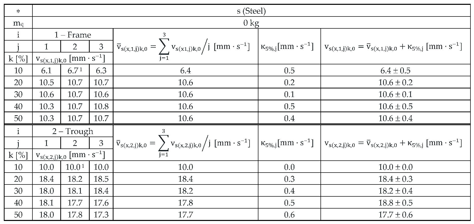
The 3 times repeated measurements of the effective values of the vibration velocity vc(x,i,j)k,0 [mm·s‒1] of the vibration of the trough (i = 1) and the steel frame (i = 2) of the vibrating feeder with electromagnetic vibration exciter, the trough of which was loaded with the mass of material m = 0 kg is supported by leaf springs made of material c ‒ Steel, are specified in Table 12.
Figure 18 indicates the graphical progression (j = 2, see Table 12) of the measured values of the effective vibration velocities vs(l,i,j)k,0 [mm·s‒1] in the direction of “x” axis (l = x) on the trough and on the steel frame of the vibrating feeder, when the trough is supported by four pieces of leaf springs (material Steel, ∗ = s). Amplitude of the trough oscillation A = k· A [mm] (k = 10%), frequency of the trough oscillation f = 50 Hz, mass of the material to be conveyed m = 0 kg.
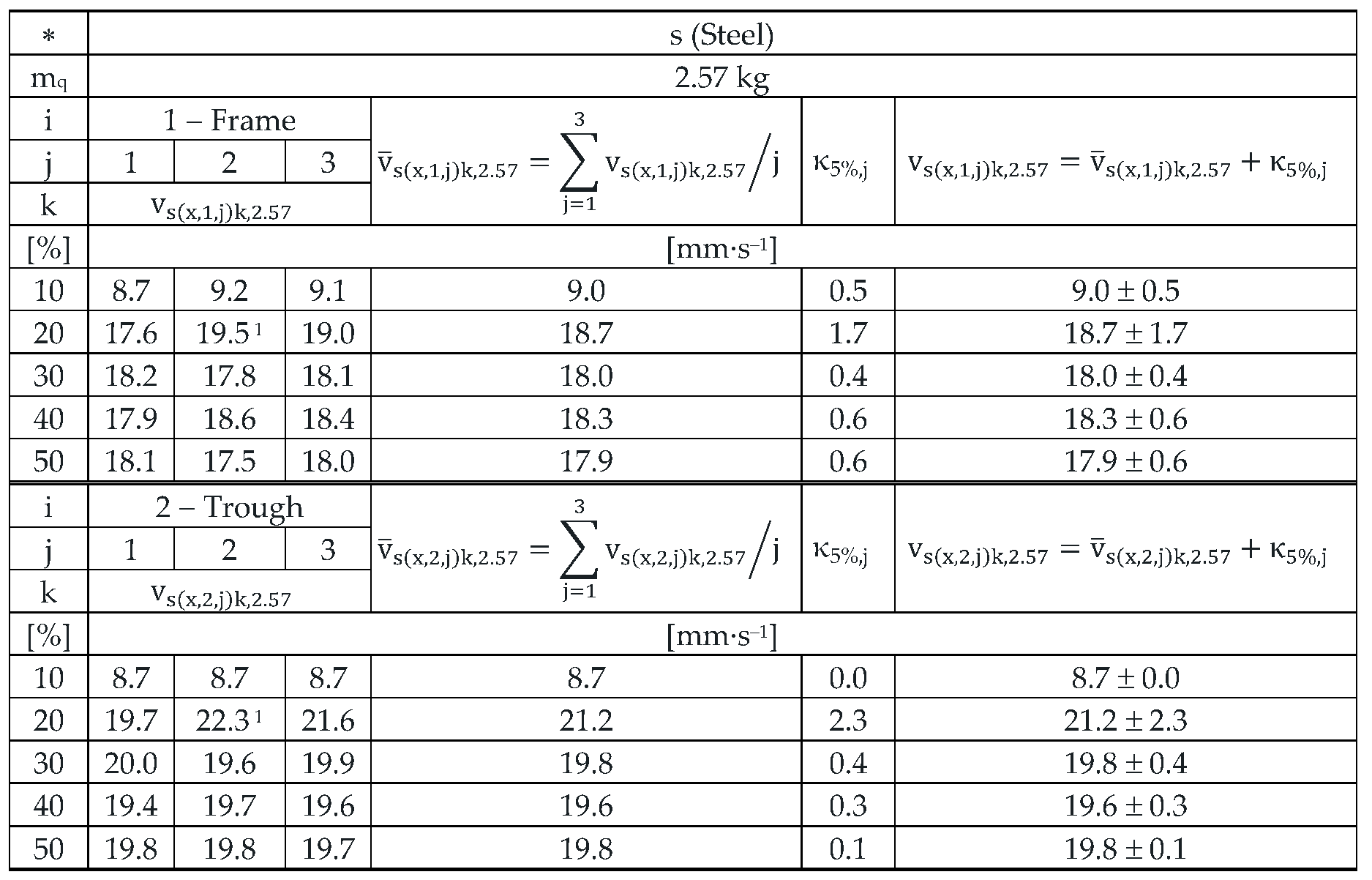
The 3 times repeated measurements of the effective values of the vibration velocity vs(x,i,j)k,2.57 [mm·s–1] of the vibration of the trough (i = 1) and the steel frame (i = 2) of the vibrating feeder with electromagnetic vibration exciter, the trough of which was loaded with the mass of material m = 2.57 kg is supported by leaf springs made of material c ‒ Steel, are specified in Table 13.
Figure 19 indicates the graphical progression (j = 2, see Table 13) of the measured values of the effective vibration velocities vs(l,i,j)k,2.57 [mm·s‒1] in the direction of “x” axis (l = x) on the trough and on the steel frame of the vibrating feeder, when the trough is supported by four pieces of leaf springs (material Steel, ∗ = s). Amplitude of the trough oscillation A = k· A [mm] (k = 20%), frequency of the trough oscillation f = 50 Hz, mass of the material to be conveyed m = 2.57 kg.
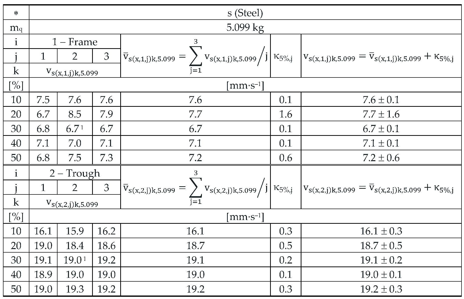
The 3 times repeated measurements of the effective values of the vibration velocity vs(x,i,j)k,5.099 [mm·s‒1] of the vibration of the trough (i = 1) and the steel frame (i = 2) of the vibrating feeder with electromagnetic vibration exciter, the trough of which was loaded with the mass of material m = 5.099 kg is supported by leaf springs made of material c ‒ Steel, are specified in Table 14.
Figure 20 indicates the graphical progression (j = 2, see Table 14) of the measured values of the effective vibration velocities vs(x,i,j)k,5.099 [mm·s‒1] in the direction of “x” axis (l = x) on the trough and on the steel frame of the vibrating feeder, when the trough is supported by four pieces of leaf springs (material Steel, ∗ = s). Amplitude of the trough oscillation A = k· A [mm] (k = 30%), frequency of the trough oscillation f = 50 Hz, mass of the material to be conveyed m = 5.099 kg.
When the vibrating feeder is used with plastic leaf springs, made using the 3D printing method from PCCF filament, the measurements of the effective vibration velocity values v∗(l,i,j)k,m [mm·s–1] only were carried out for k = 10% to 30% when the conveyed material is not present on the trough surface, and for k = 10% and 20% when the conveyed material is present on the trough (weights of mq = 2.57 kg a 5.099 kg).
The impossibility to perform the measurements at higher k [%] (k = % amplitude magnitude A [mm] set on the amplitude/frequency controller FQ1 DIG [17], see Figure 8(b)) is due to the low stiffness of the leaf springs scj [N·mm‒1] (see Table 8 and Figure 12) printed on a 3D printer from the Prusament PC Blend Carbon Fiber material Due to the low stiffness of the printed leaf springs (j = 7 to 10, Table 8) the electromagnet armature impacted on the core at k > 30%, which means that the electromagnet adhesion force Fh [N] (see Table 1) was multiple times higher than the force FMijk [N] (see Table 8), which induced a deflection yMk [mm] of the end parts of the leaf springs. This is higher than the actual distance of the armature δ [mm] from the core of the electromagnet installed as a vibration source in the vibrating feeder with electromagnetic vibration exciter (see Figure 7).
Table 15.
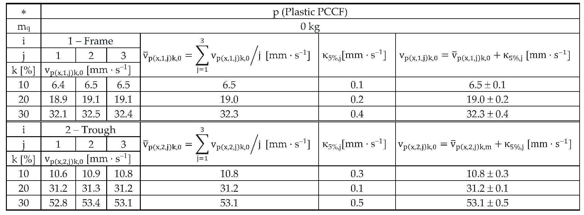
Effective vibration velocities vp(x,i,j)k,0 [mm·s‒1] of the steel frame (i = 1) and trough (i = 2) measured in the "x" axis (l = x) of the coordinate system. Load weight m = 0 kg, leaf spring material Plastic (∗ = p).
Table 15.
Effective vibration velocities vp(x,i,j)k,0 [mm·s‒1] of the steel frame (i = 1) and trough (i = 2) measured in the "x" axis (l = x) of the coordinate system. Load weight m = 0 kg, leaf spring material Plastic (∗ = p).
 |
The 3 times repeated measurements of the effective values of the vibration velocity vp(x,i,j)k,2.57 [mm·s‒1] of the vibration of the trough (i = 1) and the steel frame (i = 2) of the vibrating feeder with electromagnetic vibration exciter, the trough of which was loaded with the mass of material m = 2.57 kg is supported by leaf springs made of material p ‒ Plastic, are specified in Table 16.
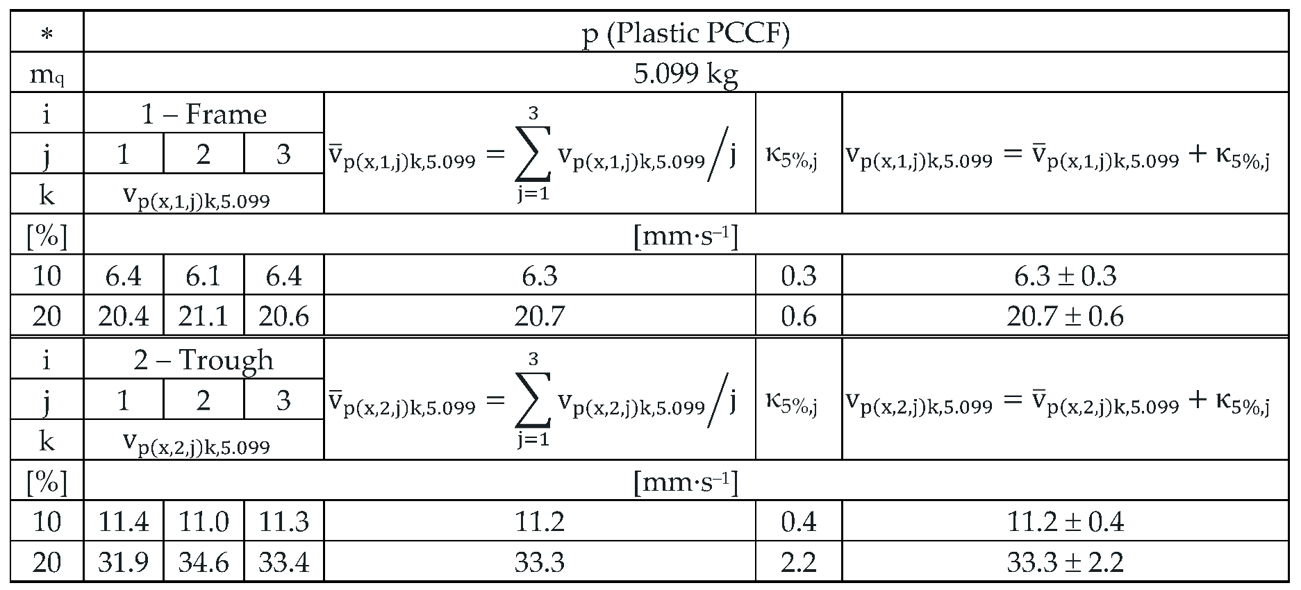
The 3 times repeated measurements of the effective values of the vibration velocity vp(x,i,j)k,5.099 [mm·s‒1] of the vibration of the trough (i = 1) and the steel frame (i = 2) of the vibrating feeder with electromagnetic vibration exciter, the trough of which was loaded with the mass of material m = 5.099 kg is supported by leaf springs made of material p ‒ Plastic, are specified in Table 17.
4. Discussion
The vibration of the trough, a vibrating feeder with an electromagnetic vibration exciter, see Figure 7(b), supported by leaf springs (made of FR4 Epoxy, Steel or Plastic PCCF materials) is transmitted through these springs to the steel frame of the vibrating feeder. The magnitude of the vibrations transmitted to the frame of the vibrating feeder varies and depends on the stiffnes sc [N·mm–1] of the used springs (see Chapter 2.2 and Chapter 3.2). If the spring stiffnesses are chosen appropriately, the vibrations transmitted to the vibrating feeder frame are multiple times lower than the vibration of the trough. The vibration of the trough is generated by a source of harmonic vibrations, the so-called vibration exciter. In this paper, an electromagnetic oscillator was used as an exciter for the measuring device (see Chapter 2.3).
The obtained results confirm the conclusion that it is possible to reduce the transmission of vibrations to the bottom layer in vibrating conveyors using leaf springs, presented in the article [42] by J. Michalczyk and P. Czubak.
The measurements of the effective vibration velocities (see Chapter 3.3) indicate that when using leaf springs made of FR4 Epoxy (optimally chosen stiffness of leaf springs), with a total stiffness of scc = 47.8 N·mm–1, the vibration of the trough is higher in the case of an unloaded trough with conveyed material (the owne weight of the trough mz = 3.37 kg), see Table 9 and Figure 21, and lower in the case when there is material on the trough (mq = 2.57 kg or 5.099 kg), see Table 10, Table 11 and Figure 21.
When using leaf springs made of steel (high stiffness of leaf springs), with a total stiffness of scs = 107.1 N·mm–1, the vibration of the trough is higher when the trough is not loaded with the material being conveyed, see Table 12 and Figure 22, as well as when there is material loaded on the trough (mq = 2.57 kg or 5.099 kg), see Table 13, Table 14 and Figure 22.
When using Plastic PCCF leaf springs (low stiffness leaf springs), with a total stiffness of scp = 4.4 N·mm‒1, the vibration of the trough is also higher when the trough is unloaded with material (trough dead weight mz = 3.37 kg), see Table 15 and Figure 23, and when there is material on the trough (mq = 2.57 kg or 5.099 kg), see Table 16, Table 17 and Figure 23.
To analyse and justify whether the signals obtained by the acceleration sensors (i.e. the measured effective vibration speeds) can be used to remotely diagnose the working condition of the vibrating feeder, the measured values of the effective spring vibration speeds for k = 40% only, indicated in Table 9 to Table 11, will be examined in more detail.
The measured values, when using leaf springs made of FR4 Epoxy and zero filling of the vibrating feeder trough with the conveyed material (mq = 0 kg) indicate that the effective vibration velocity detected on the steel frame of the vibrating feeder reaches the value of 38.5 mm·s–1 (see Table 9) and on the trough 65.1 mm·s–1. On the steel frame, the effective vibration velocity takes 59.1% of the value of the effective vibration velocity measured on the trough.
With the mass of material to be conveyed on the trough mq = 2.57 kg, both the effective vibration velocities measured on the steel frame and on the trough are the same 56.8 mm·s‒1, see Table 10.
With a conveyed material mass on the trough of mq = 5.099 kg, the mean value of the effective vibration velocity measured on the steel frame is 24.6 mm·s–1 and on the trough 12.5 mm·s–1, see Table 11. On a steel frame, the effective vibration velocity takes 50.8% of the value of the effective vibration relocity measured on the trough.
For leaf springs with optimum stiffness (material FR4 Epoxy − scc = 47.8 N·mm–1) it applies that the mean values of the measured effective vibration velocities take the highest value (65.1 mm·s–1 see Table 9) and decrease with increasing mass of material on the trough (56.8 mm·s–1 pro mq = 2.57 kg, see Table 10 and 12.5 mm·s‒1 for mq = 5.099 kg, see Table 11).
The measured values of the effective vibration velocities, when using leaf springs made of Steel, (see Table 12 to Table 14) alo indicate (according to the mean values of the effective vibration velocities) whether or not the material to be conveyed is on the trough and what mass size it takes on.
On the steel frame; at k = 40% and at zero filling of the trough of the vibrating feeder with the conveyed material (mq = 0 kg); the value of the mean effective vibration velocity was measured to be 10.6 mm·s–1 and 18.8 mm·s–1 on the trough, respectively, using steel springs. Thus, on the steel frame, the effective vibration velocity is 56.4% of the effective vibration velocity measured on the trough.
With the weight of the material conveyed on the trough mq = 2.57 kg, the mean value of the effective vibration velocity measured on the steel frame is 93.4% of the value of the effective vibration velocity measured on the trough.
With the weight of the material conveyed on the trough mq = 5.099 kg, the mean value of the effective vibration velocity measured on the steel frame is 37.4% of the value of the effective vibration velocity measured on the trough.
For leaf springs that have high stiffness (material Steel − scs = 107.1 N·mm–1) it applies that the mean values of the measured effective vibration velocities are the lowest (18.8 mm·s–1 see Table 12) in the absence of the conveyed material on the trough and increase with increasing weight of the material on the trough (19.6 mm·s–1 pro mq = 2.57 kg, see Table 13 and 19.0 mm·s–1 for mq = 5.099 kg, see Table 14).
Measured values of the effective vibration velocities when using leaf springs made of Plastic PCCF (see Table 15 to Table 17) also indicate that it can be predicted from the measured values of the effective vibration velocities whether or not there is material (and if so and of what mass size) to be conveyed on the trough of the vibrating feeder.
During the measurements carried out on the laboratory device, i.e. a vibrating feeder with an electromagnetic vibration exciter, using low stiffness leaf springs (scp = 4.4 N·mm–1), it was not possible to set the amplitude/frequency controller - FQ1 DIG Process Controller [17] to higher values of k [%] than 20%. This was due to the low stiffness of the leaf springs (made of Plastic PCCF), which caused the armature to come into contact with the core of the electromagnet – a situation that is unacceptable in electromagnetic exciters used in practice.
On the steel frame; at k = 20% and with zero filling of the vibrating feeder trough with the conveyed material (mq = 0 kg); the value of the mean effective vibration velocity has been measured to be 31.2 mm·s–1 and 19.0 mm·s–1 at the trough. Thus, on a steel frame, the effective vibration velocity reaches 60.9% of the effective vibration velocity measured on the trough.
With the weight of the material conveyed on the trough mq = 2.57 kg, the mean value of the effective vibration velocity measured on the steel frame is 97.2% of the value of the effective vibration velocity measured on the trough.
With the weight of the material conveyed on the trough mq = 5.099 kg, the mean value of the effective vibration velocity measured on the steel frame is 62.2% of the value of the effective vibration velocity measured on the trough.
Based on the above conclusions of the measured values of the effective vibration velocities (see Table 9 to Table 17 and Figure 21 to Figure 23), it can be predicted with a high degree of probability that it is possible to estimate remotely whether or not there is material being conveyed on the trough of the vibrating feeder and also that there is a larger or smaller mass quantity of material on the trough.
Conclusion: From the measurements carried out in the article [4] by L. Hrabovský et al. it can be traced that with inappropriately selected stiffnesses of springs supporting the trough of the vibrating conveyor, it can be traced from the analysis of vibration signals (transmitted to the machine frame) generated by sensors that the vibration of a loaded trough (mm > 0 kg) is higher than the vibration of an unloaded trough (mm = 0 kg) of the vibrating conveyor.
From the analysis of the measured values presented in Chapter 3.3 it can be concluded that by monitoring the vibrations (using vibration sensors) transmitted to the supporting frame of the vibrating feeder, information about its working properties can be obtained, thus confirming the intended objective of the conducted experiments.
The information, i.e. the electrical signals, detected by the vibration sensors can be used to diagnose the working operation of vibrating feeders in locations that may be in a considerable distance from where the vibrating feeder is installed. Such diagnostics of vibrating feeder parameters can provide controllers in the control centre with the information on whether the required amount of material is on the trough of the vibrating feeder, whether the vibrating feeder is in an optimal operating state or in a fault state.
5. Conclusions
In the presented paper, the tables indicate the effective vibration velocity values obtained by measurements, detected by acceleration sensors, on the trough surface and on the frame of the vibrating feeder model with electromagnetic vibration exciter. The trough of the vibrating conveyor is supported by three types of leaf springs, which differ in terms of their stiffness (spring characteristics). The harmonic oscillation of the trough is induced by an electromagnetic oscillator, the frequency and amplitude of oscillation of which is controlled by the controller (amplitude/frequency regulator – FQ1 DIG Process Controller).
The main objective of the realized signal measurements (which define the magnitude of the vibrations in three mutually perpendicular planes) was to determine whether (with varying input values, namely the amplitude of vibrations, the mass of the conveyed material) it is possible to obtain (from the measured magnitudes of the vibrations acting on the frame of the vibrating conveyor) information about the operating characteristics and the mass of material to be conveyed on the trough with respect to the stiffness of the rubber springs supporting the vibrating masses.
Acceleration magnitudes of the effective vibration velocity values measured by sensors have demonstrated and confirmed that if springs of a particular stiffness supporting the vibrating trough are selected appropriately, it is possible to remotely monitor the correct operational operation of the vibratory conveyor and to have information that the required mass quantity of conveyed/sorted material is on the trough of the vibratory machine.
Knowing the magnitude of the vibrations acting on the frame of a particular vibrating feeder (obtained by sensor measurements), with known values of the stiffness of the springs supporting the trough, it is also possible to trace the failure state of their working activities, or to obtain information about the failure or damage of the rubber or steel coil cylindrical springs (used on the vibrating machine).
Signals indicating the magnitude of the vibration values acting on the frame of vibrating conveyors/sorting machines, transmitted to the control station, allow remote monitoring of the operation of vibrating machines at any time without the need for physical inspection of these devices by authorized persons at a place of their installation.
The obtained data on the magnitudes of the measured signals detected by the vibration sensors allowed to confirm the correctness of the initial idea that (with appropriately designed machine parts) it is possible to monitor the proper working operation and the failure state of vibrating conveyors under operating conditions.
The current trend towards digitalization and computer-controlled or monitored optimum operation of conveyor handling equipment (including vibrating feeders) heavily relies on sensors, measuring equipment and digital signal transmission over any distance.
Author Contributions
Conceptualization, L.H.; methodology, L.H.; software, S.P.; validation, L.H. and R.B.; formal analysis, L.H. and S.P.; investigation, L.H.; resources, L.H.; data curation, L.H., V.G. and R.B.; writing—original draft preparation, L.H.; writing—revie and editing, L.H.; visualization, L.H.; supervision, S.P.; project administration, L.H.; funding acquisition, L.H. All authors have read and agreed to the published version of the manuscript.
Funding
This research was funded by “Research and innovation of modern processes and technologies in industrial practice”, grant number SP2025/001” and was funded by MŠMT ČR (Ministry of education youth and sports).
Data Availability Statement
Measured data of effective vibration speed values v∗(l,i,j)k,m [mm·s-1], listed from Table 9 to Table 17 and processed using DEWESoftX software, can be sent in case of interest, by prior written agreement, in *.DXD (DewesoftX Data File) format or *.XLSX (Microsoft Excel) *.XLSX (Microsoft Excel) format.
Acknowledgments
The researchers of the SP2025/001 project express their gratitude for the financial support provided by the founder of the Student Grant Competition (hereinafter referred to as SGS), the VSB - Technical University of Ostrava, 17. listopadu 2172/15, 708 00 Ostrava-Poruba, Czech Republic. This work was supported by the Ministry of Education, Youth and Sports of the Czech Republic.
Conflicts of Interest
The authors declare no conflict of interest. The funders had no role in the design of the study; in the collection, analyses, or interpretation of data; in the writing of the manuscript; or in the decision to publish the results.
References
- Varoto, P. S., de Oliveira, L. P. (2002). Interaction between a vibration exciter and the structure under test. Sound and vibration 2002, 36(10), 20-26.
- Lanets, O., Kachur, O., Korendiy, V., Lozynskyy, V. Controllable Crank Mechanism for Exciting Oscillations of Vibratory Equipment. In: Ivanov, V., Pavlenko, I., Liaposhchenko, O., Machado, J., Edl, M. (eds) Advances in Design, Simulation and Manufacturing IV. DSMIE 2021. Lecture Notes in Mechanical Engineering. Springer, (29 May 2021). [CrossRef]
- Nigus, H. Kinematics and load formulation of engine crank mechanism. Mechanics, Materials Science & Engineering Journal 2015, . [CrossRef]
- Hrabovsky, L., Pravda, S., Fries, M. Sensor Monitoring of Conveyor Working Operation with Oscillating Trough Movement. Sensors 2025, 25(8), 2466. [CrossRef]
- Anekar, N., Ruiwale, V. V., Nimbalkar, S., Rao, P. Design and testing of unbalanced mass mechanical vibration exciter. International Journal of Research in Engineering and Technology 2014, 3(8), 107-112.
- Osadchyy, V., Nazarova, O., Hutsol, T., Glowacki, S., Mudryk, K., Bryś, A., Tulej W., Sojak, M. Adjustable vibration exciter based on unbalanced motors. Sensors 2023, 23(4), 2170. [CrossRef]
- Kim, J. H., Kim, J. H., Jeong, S. H., Han, B. W. Design and experiment of an electromagnetic vibration exciter for the rapping of an electrostatic precipitator. Journal of Magnetics 2012, 17(1), 61-67. [CrossRef]
- Ibadullaev, M., Nuraliyev, A., Yesenbekov, A. (2023, January). Resonance electromagnetic exciter with nonlinear power supply. In AIP Conference Proceedings (Vol. 2552, No. 1). AIP Publishing. [CrossRef]
- Czubak, P., Gajowy, M. Influence of selected physical parameters on vibroinsulation of base-exited vibratory conveyors. Open Engineering 2022, 12(1), 382–393. [CrossRef]
- Surowka, W., Czubak, P. Transport properties of the new vibratory conveyor at operations in the resonance zone. Open Engineering 2021, 11(1), 1214–1222. [CrossRef]
- Brain, M., Looper, L. How electromagnets work. HowStuffWorks 2000.
- Sanz, S., Garcia-Tabares, L., Moya, I., Obradors, D., Toral, F. Evaluation of magnetic forces in permanent magnets. IEEE Transactions on Applied Superconductivity 2010, 20(3), 846–850.
- Reyne, G., Sabonnadiere, J., Coulomb, J., Brissonneau, P. A survey of the main aspects of magnetic forces and mechanical behaviour of ferromagnetic materials under magnetisation. IEEE Transactions on magnetics 2003, 23(5), 3765–3767. . [CrossRef]
- Bespalov, A. L., Svidrak, I. G., Boiko, O. O. Improving the performance of vibration feeders with an electromagnetic vibration drive and a combined vibration system. Scientific Messenger of LNU of Veterinary Medicine and Biotechnologies. Series: Food Technologies 2020, 22(93), 26–30. [CrossRef]
- Bespalov, A. L., Svidrak, I. G., Boiko, O. O. Increase the functionality of vibration feeders with electromagnetic vibration. Scientific Messenger of LNU of Veterinary Medicine and Biotechnologies. Series: Food Technologies 2021, 23(95), 33–37. [CrossRef]
- Despotovic, Z. V., Lecic, M., Jovic, M. R., Djuric, A. (2014). Vibration control of resonant vibratory feeders with electromagnetic excitation. FME Transactions 2014, 42(4), 281–289.
- Electronic control circuits for electromagnetic vibrators. Available online https://www.mpelettronic.it/Catalogo/Eng/catalogo%20inglese.pdf. (accessed on 18 March 2025).
- Korendiy, V., Kachur, O., Hurey, I., Predko, R, Palash, R, Havrylchenko, O. Modelling and experimental investigation of the vibratory conveyor operating conditions. Vibroengineering PROCEDIA 2022, 47, 1–7. [CrossRef]
- Cieplok, G. Self-synchronization of drive vibrators of an antiresonance vibratory conveyor. Journal of Theoretical and Applied Mechanics 2023. 501–511. [CrossRef]
- Deng, J., Li, C., Zhao, Z., Tu, F., Yu, H. Numerical simulation of magnetic flux and force in electromagnetic forming with attractive force. Journal of materials processing technology 2007, 184(1-3), 190–194. [CrossRef]
- Kawase, Y., Ito, S. Analysis of attractive force of pull-type single phase AC electromagnets. IEEE transactions on magnetics 2002, 26(2), 1046–1049. [CrossRef]
- Borcherts, R., Davis, L. Lift and drag forces for the attractive electromagnetic suspension systems. IEEE Transactions on Magnetics 2003, 10(3), 425-428. [CrossRef]
- Popa, I., Dolan, A. I. Static force characteristic of e-type single phase AC electromagnets. In 2012 International Conference on Applied and Theoretical Electricity (ICATE), Craiova, Romania, (25–27 October 2012).
- Kawase, Y., Ito, S. Analysis of attractive force of pull-type single phase AC electromagnets. IEEE transactions on magnetics 2002, 26(2), 1046-1049. https://doi.org/10.1109/20.106500.
- He, W., Wang, C., Yu, M., Shen, R., Jia, S. Closed-double-magnetic circuit for a long-stroke horizontal electromagnetic vibration exciter. IEEE transactions on magnetics 2012, 49(8), 4865–4872. https://doi.org/10.1109/TMAG.2012.2225109.
- Sokolov, I. J., Babitsky, V. I., Halliwell, N. A. Autoresonant vibro-impact system with electromagnetic excitation. Journal of Sound and Vibration 2007, 308(3–5), 375–391. https://doi.org/10.1016/j.jsv.2007.04.010.
- Michalik, P., Dobransky, J., Hrabovsky, L., Petrus, M. Assessment of the manufacturing possibility of thin-walled robotic portals for conveyance workplaces. Advances in Science and Technology. Research Journal 2018, 12(1), 338–345. http://dx.doi.org/10.12913/22998624/87063.
- Konofagou, E. E., Hynynen, K. Localized harmonic motion imaging: theory, simulations and experiments. Ultrasound in medicine & biology 2003, 29(10), 1405–1413. https://doi.org/10.1016/S0301-5629(03)00953-0.
- Somroob, S., Wattanakasiwich, P. Investigating student understanding of simple harmonic motion. In Journal of Physics: Conference Series (Vol. 901, No. 1, p. 012123). IOP Publishing. Rayong, Thailand, (24–26 May 2017).
- Ogonowski, S., Krauze, P. Trajectory Control for Vibrating Screen with Magnetorheological Dampers. Sensors 2022, 22(11), 4225. [CrossRef]
- Pesik, M., Nemecek, P. Vibroisolation of Vibratory Conveyors. Applied Mechanics and Materials 2015, 732, 253–256. [CrossRef]
- Strain gauge force sensor MCF30. Available online: https://www.comforia.cz/public/uploads/pdf_cz/MCF30_2020-04.pdf (accessed on 18 February 2024).
- DewesoftX 2024.5 Patch–2. Available online: https://downloads.dewesoft.com/dewesoftx-previous/DewesoftX_2024.5_Patch2_x64.exe (accessed on 11 September 2024).
- Technical reference manual. Available online: https://d36j349d8rqm96.cloudfront.net/3/6/Dewesoft-DS-NET-Manual-EN.pdf (accessed on 3 July 2024).
- Prusament PC Blend Carbon Fiber. Available online: https://prusament.com/materials/prusament-pc-blend-carbon-fiber/ (accessed on 7 June 2025).
- Long positioning tables with PA(E). Available online: https://mnsystems.cz/images/mm/Katalog/02_pt-system_19-07-10_dt-eng_katalog-mme_1.pdf (accessed on 28 April 2025).
- Technical reference manual DS-NET V20–1. Available online: https://d36j349d8rqm96.cloudfront.net/3/6/Dewesoft-DS-NET-Manual-EN.pdf (accessed on 3 September 2024).
- Hrabovsky, L., Pravda, S., Sebesta, R., Novakova, E., Kurac, D. Detection of a Rotating Conveyor Roller Casing Vibrations on a Laboratory Machine. Symmetry 2023, 15(9), 1626. [CrossRef]
- Technical reference manual SIRIUS® V25–1. Available online: https://downloads.dewesoft.com/manuals/dewesoft-sirius-manual-en.pdf (accessed on 25 July 2024).
- Madr, V.; Knejzlik, J., Kopecny, I., Novotny, I. Fyzikální Měření (In English: Physical Measurement); SNTL Praha: Czech Republic, 1991; p. 304, ISBN 80-03-00266-4.
- Hrabovsky, L., Pravda, S., Fries, M. Sensor Monitoring of Conveyor Working Operation with Oscillating Trough Movement. Sensors 2025, 25(8), 2466. [CrossRef]
- Michylczyk, J., Czubak, P. Latent reactions in suspension systems of vibratory machines supported by leaf springs. Polish Academy of Sciences, Committee on Machine Building 2000, 47(4), ISSN 0004-0738. https://journals.pan.pl/Content/125384/PDF/4_MECHANICAL_47_2000_4_Michalczyk_Latent.pdf.
Figure 1.
Dimensional sketch of the electromagnet, a/b [m] - length/width of the electromagnet core, δ [m] - armature clearance (air gap).
Figure 1.
Dimensional sketch of the electromagnet, a/b [m] - length/width of the electromagnet core, δ [m] - armature clearance (air gap).

Figure 2.
Harmonic oscillation of the vibrating conveyor trough, (a) components yx(t) [m] a yy(t) [m] of the trough deflection, (b) harmonic oscillation parameters.
Figure 2.
Harmonic oscillation of the vibrating conveyor trough, (a) components yx(t) [m] a yy(t) [m] of the trough deflection, (b) harmonic oscillation parameters.
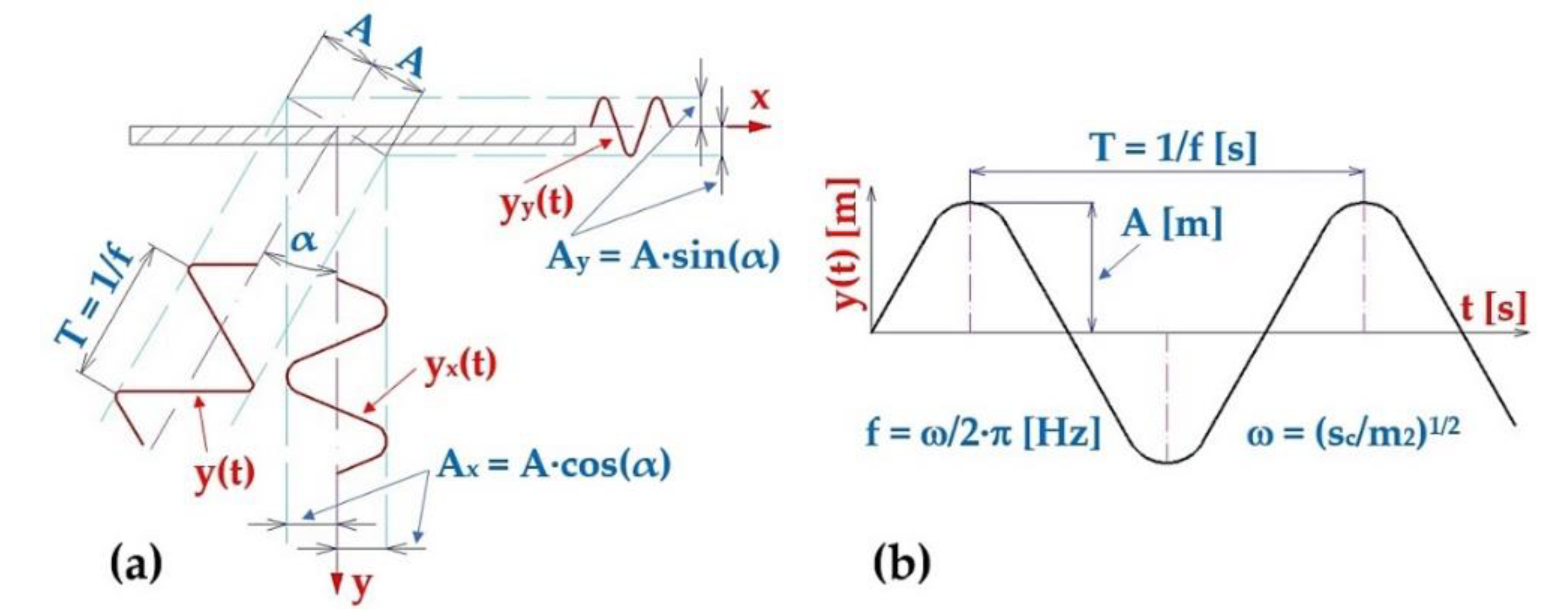
Figure 3.
Laboratory device for detecting the magnitude of the electromagnet's holding force (a) 2D dimensional sketch, (b) 3D model, (c) implementation. 1 ‒ electromagnet, 2 ‒ electromagnet armature, 3 ‒ force sensor, 4 ‒ support frame.
Figure 3.
Laboratory device for detecting the magnitude of the electromagnet's holding force (a) 2D dimensional sketch, (b) 3D model, (c) implementation. 1 ‒ electromagnet, 2 ‒ electromagnet armature, 3 ‒ force sensor, 4 ‒ support frame.
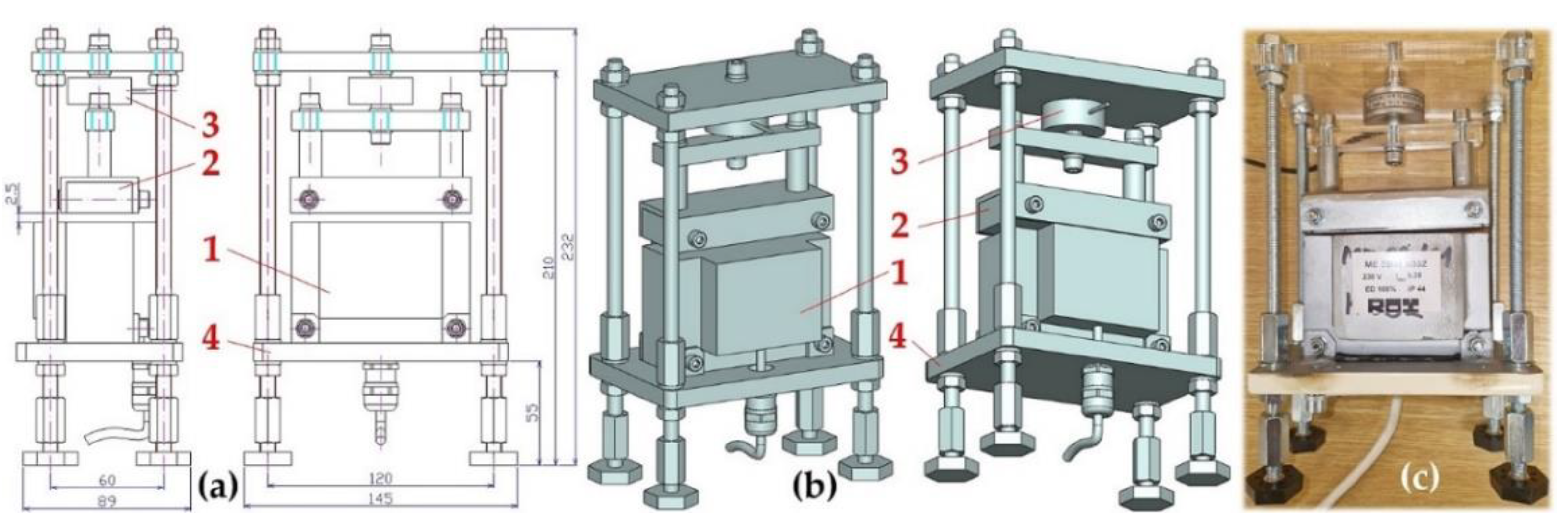
Figure 4.
Measuring chain ‒ a sequence of interconnected instruments and devices that enable the detection and processing of measured signals.
Figure 4.
Measuring chain ‒ a sequence of interconnected instruments and devices that enable the detection and processing of measured signals.
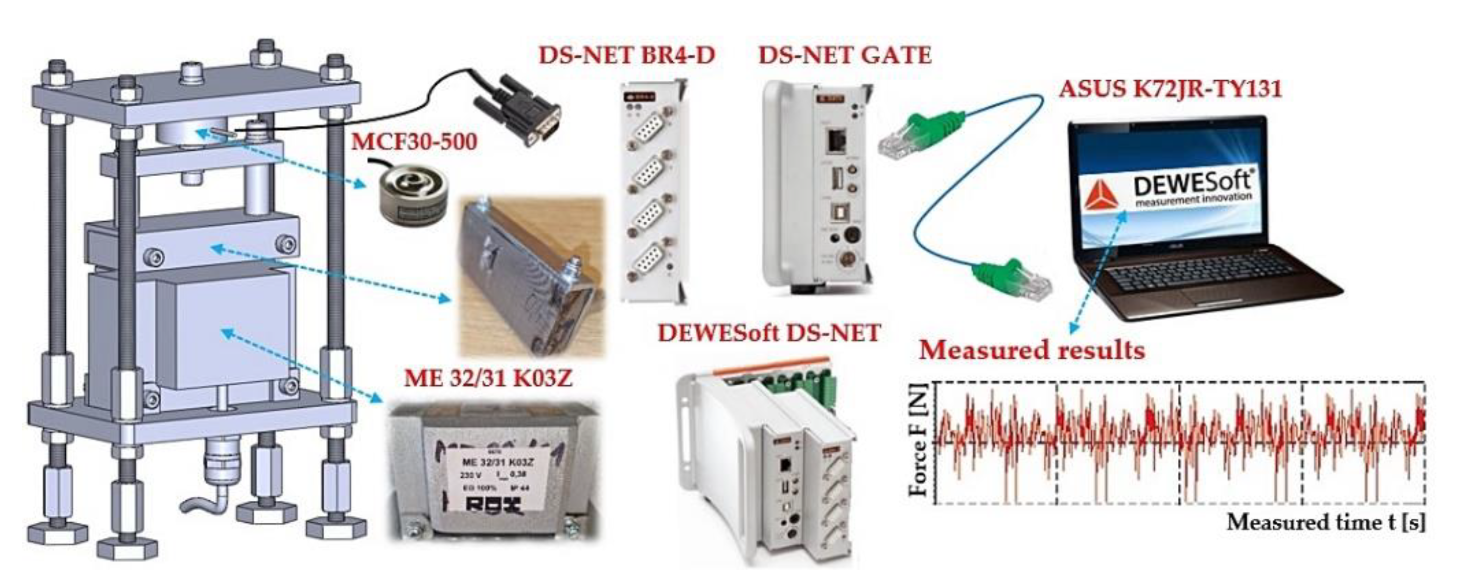
Figure 5.
(a) leaf springs made of FR4 Epoxy, (b) deflection yMijk [m] of a leaf spring of length Ls [m] loaded with force FMijk [N], (c) of measuring the deflection of the leaf spring on laboratory device.
Figure 5.
(a) leaf springs made of FR4 Epoxy, (b) deflection yMijk [m] of a leaf spring of length Ls [m] loaded with force FMijk [N], (c) of measuring the deflection of the leaf spring on laboratory device.
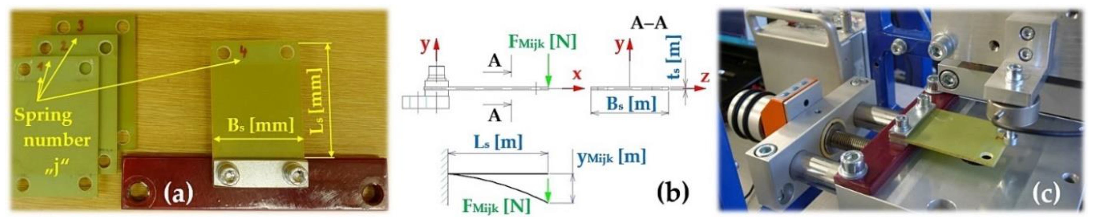
Figure 6.
Laboratory device for measuring the stiffness of leaf springs, (a) dimensional sketch, (b) 3D model, (c) attachment of the leaf spring to the flat bar by a bolted connection, (d) implemented device. 1 ‒ steel frame, 2, 4 ‒ positioning table PT7312-PA, 3 ‒ MCF30-500 force transducer, 5 ‒ leaf spring.
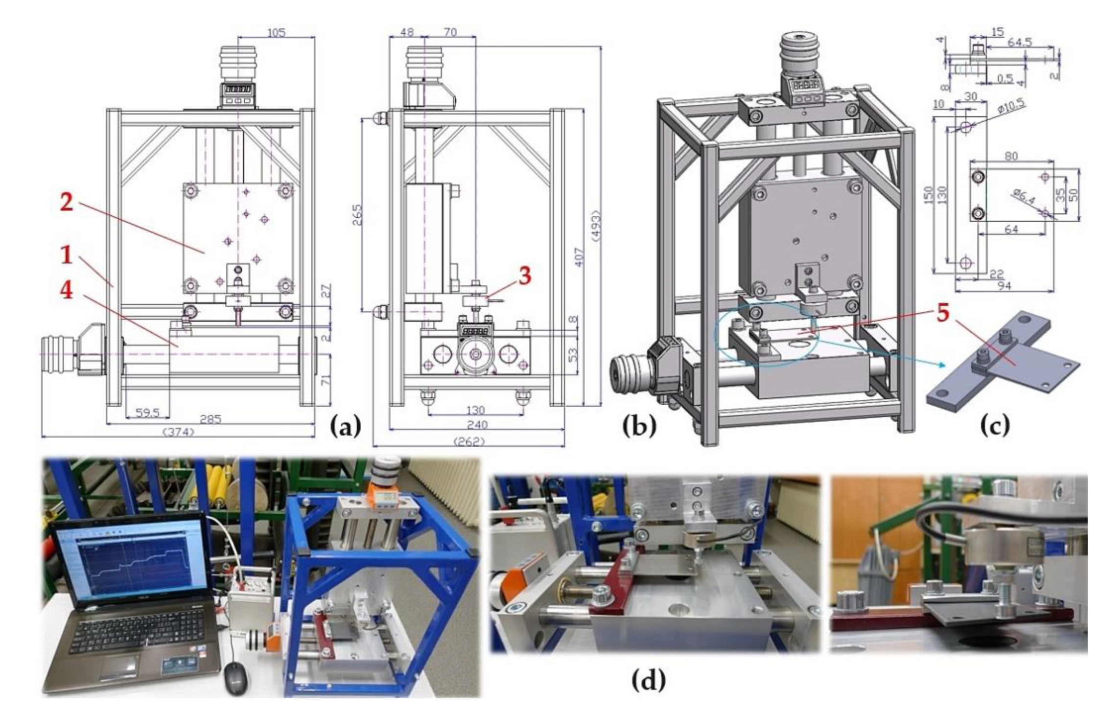
Figure 7.
The vibrating feeder with electromagnetic vibration exciter (a) dimensional sketch and 3D model, (b) implemented measuring device. 1 ‒ steel trough, 2 ‒ steel frame, 3 ‒ leaf spring, 4 ‒ electromagnet, 5 ‒ armature of the electromagnet, 6 ‒ amplitude/frequency regulator - FQ1 DIG.
Figure 7.
The vibrating feeder with electromagnetic vibration exciter (a) dimensional sketch and 3D model, (b) implemented measuring device. 1 ‒ steel trough, 2 ‒ steel frame, 3 ‒ leaf spring, 4 ‒ electromagnet, 5 ‒ armature of the electromagnet, 6 ‒ amplitude/frequency regulator - FQ1 DIG.
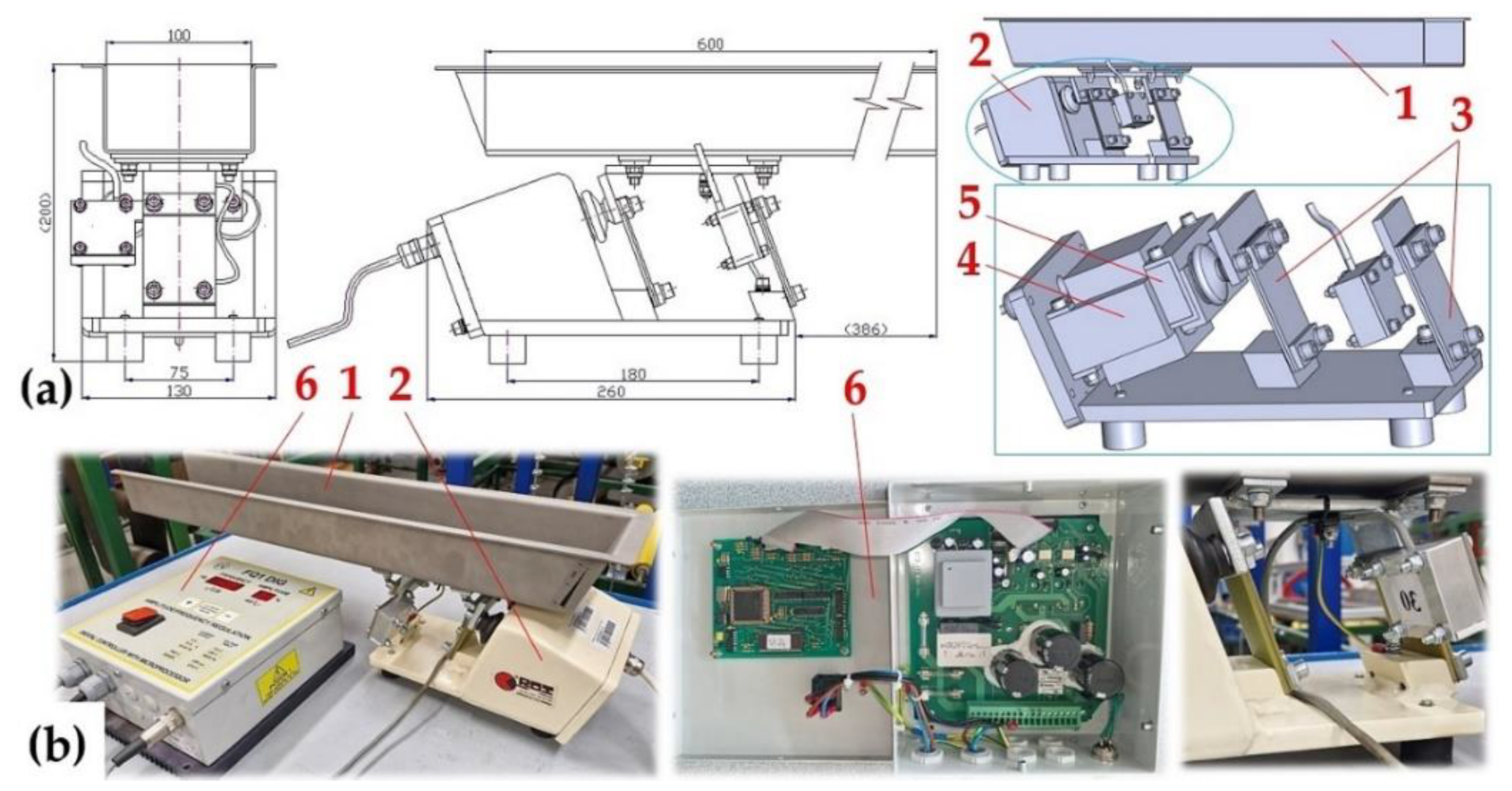
Figure 8.
The vibrating feeder with electromagnetic vibration exciter. 1 ‒ steel trough, 2 ‒ steel frame, 3 ‒ acceleration sensors, 4 ‒ amplitude/frequency controller, 5 ‒ measuring apparatus, 6 ‒ PC with DEWESoft X software.
Figure 8.
The vibrating feeder with electromagnetic vibration exciter. 1 ‒ steel trough, 2 ‒ steel frame, 3 ‒ acceleration sensors, 4 ‒ amplitude/frequency controller, 5 ‒ measuring apparatus, 6 ‒ PC with DEWESoft X software.
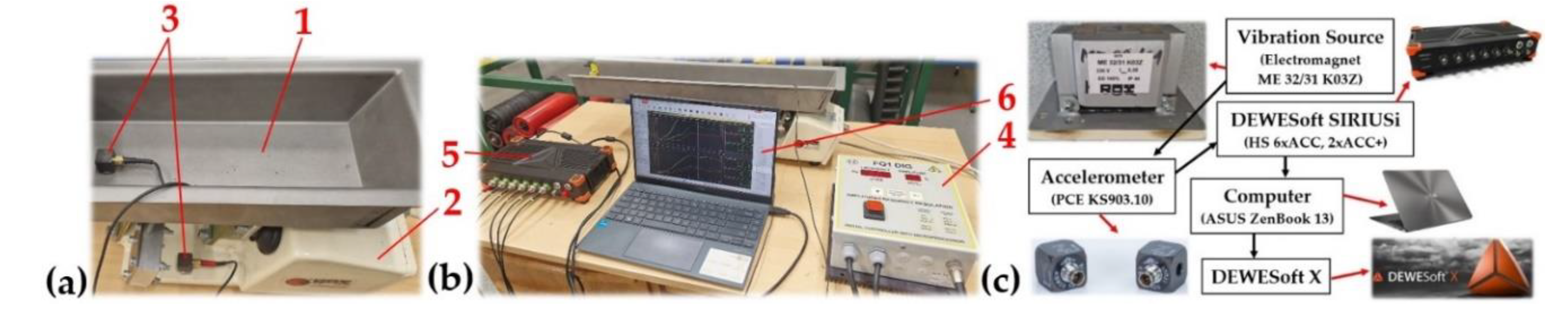
Figure 15.
Measured values of effective vibration velocities vc(l,i,1)10,0 [mm·s–1] in three mutually perpendicular planes of (a) trough supported by 4 FR4 Epoxy leaf springs, (b) steel frame of vibrating feeder.
Figure 15.
Measured values of effective vibration velocities vc(l,i,1)10,0 [mm·s–1] in three mutually perpendicular planes of (a) trough supported by 4 FR4 Epoxy leaf springs, (b) steel frame of vibrating feeder.
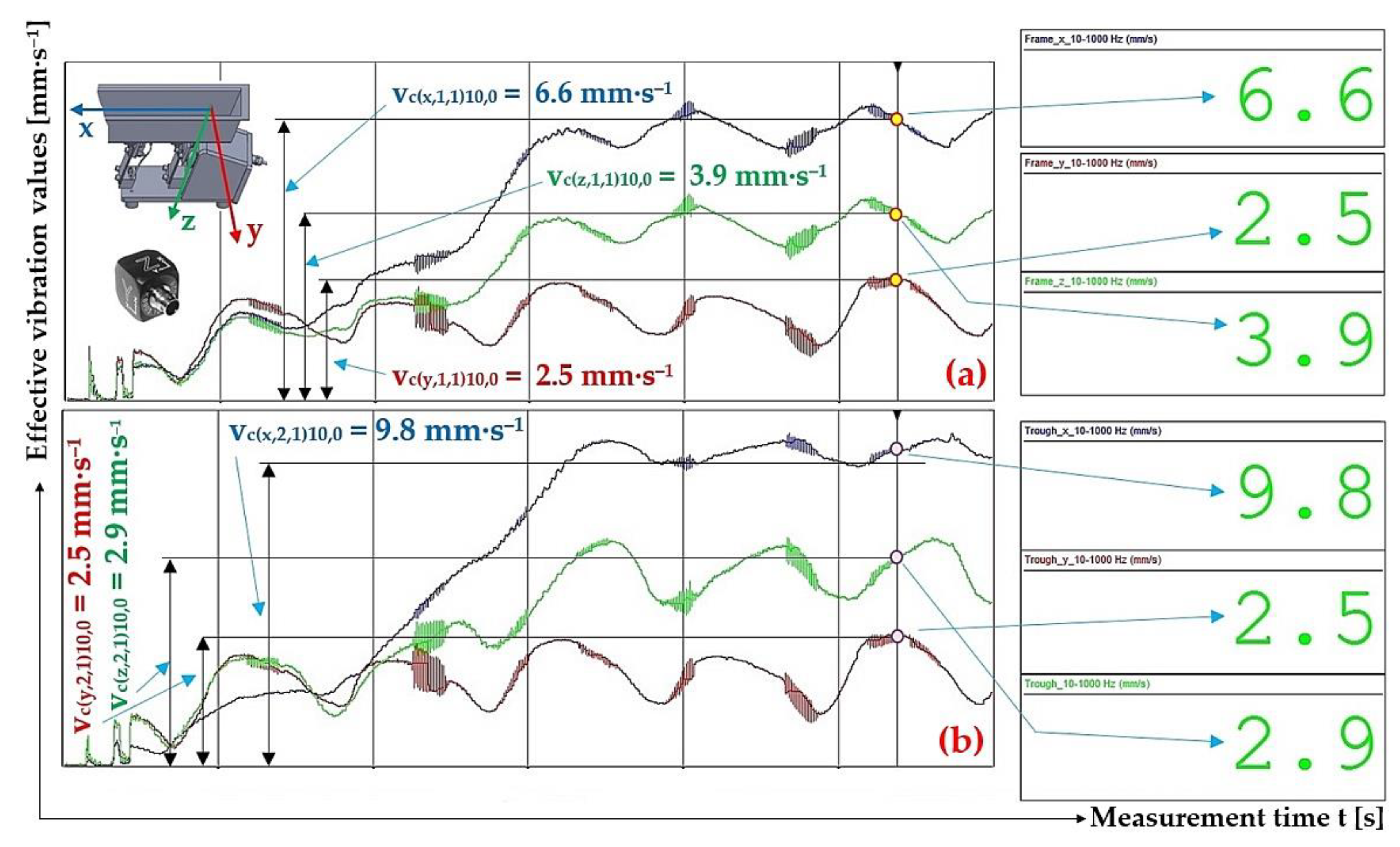
Figure 16.
Measured values of the effective vibration velocity vc(x,i,1)20,2.57 [mm·s–1] in the direction of the x-axis of the trough (supported by 4 FR4 Epoxy leaf springs) and the steel frame of the vibrating feeder.
Figure 16.
Measured values of the effective vibration velocity vc(x,i,1)20,2.57 [mm·s–1] in the direction of the x-axis of the trough (supported by 4 FR4 Epoxy leaf springs) and the steel frame of the vibrating feeder.
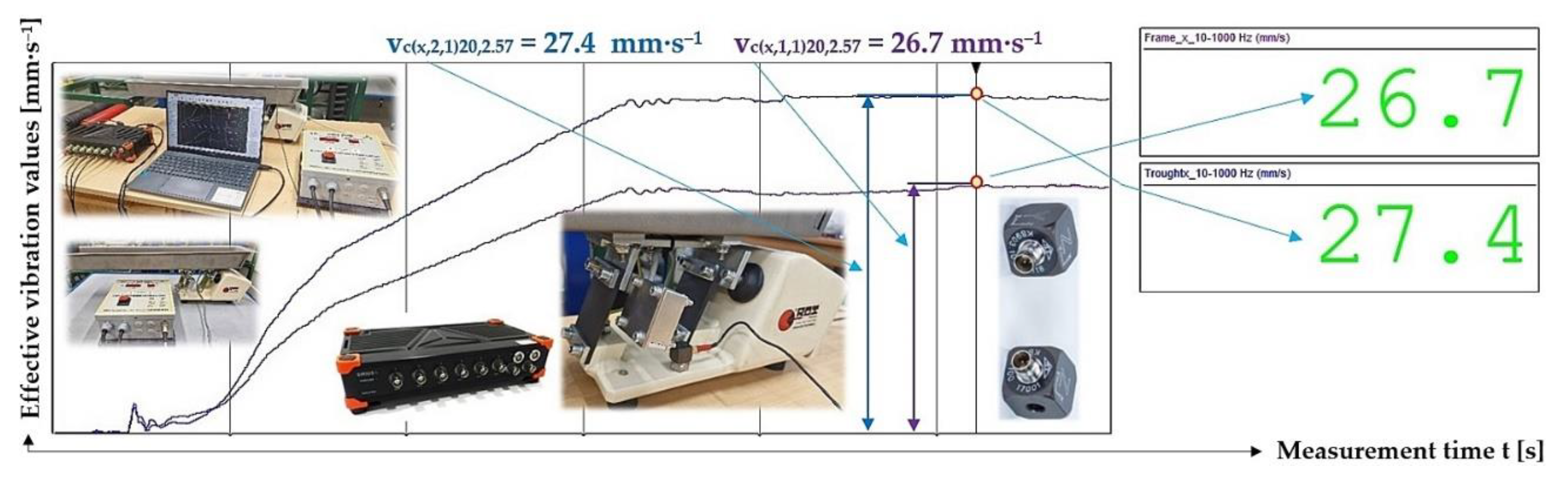
Figure 17.
Measured values of the effective vibration velocity vc(x,i,1)30,5.099 [mm·s‒1] in the direction of the x-axis of the trough (supported by 4 FR4 Epoxy leaf springs) and the steel frame of the vibrating feeder.
Figure 17.
Measured values of the effective vibration velocity vc(x,i,1)30,5.099 [mm·s‒1] in the direction of the x-axis of the trough (supported by 4 FR4 Epoxy leaf springs) and the steel frame of the vibrating feeder.
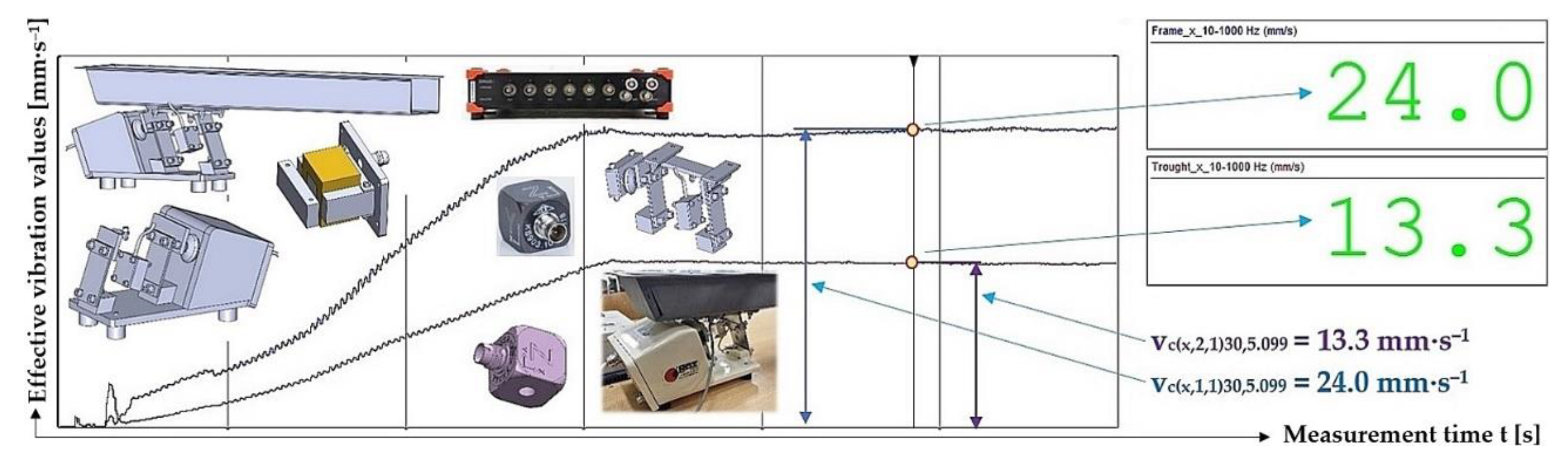
Figure 18.
Measured values of the effective vibration velocity vs(x,i,2)10,0 [mm·s‒1] in the direction of the x-axis of the trough (supported by 2 Steel leaf springs) and the steel frame of the vibrating feeder.
Figure 18.
Measured values of the effective vibration velocity vs(x,i,2)10,0 [mm·s‒1] in the direction of the x-axis of the trough (supported by 2 Steel leaf springs) and the steel frame of the vibrating feeder.
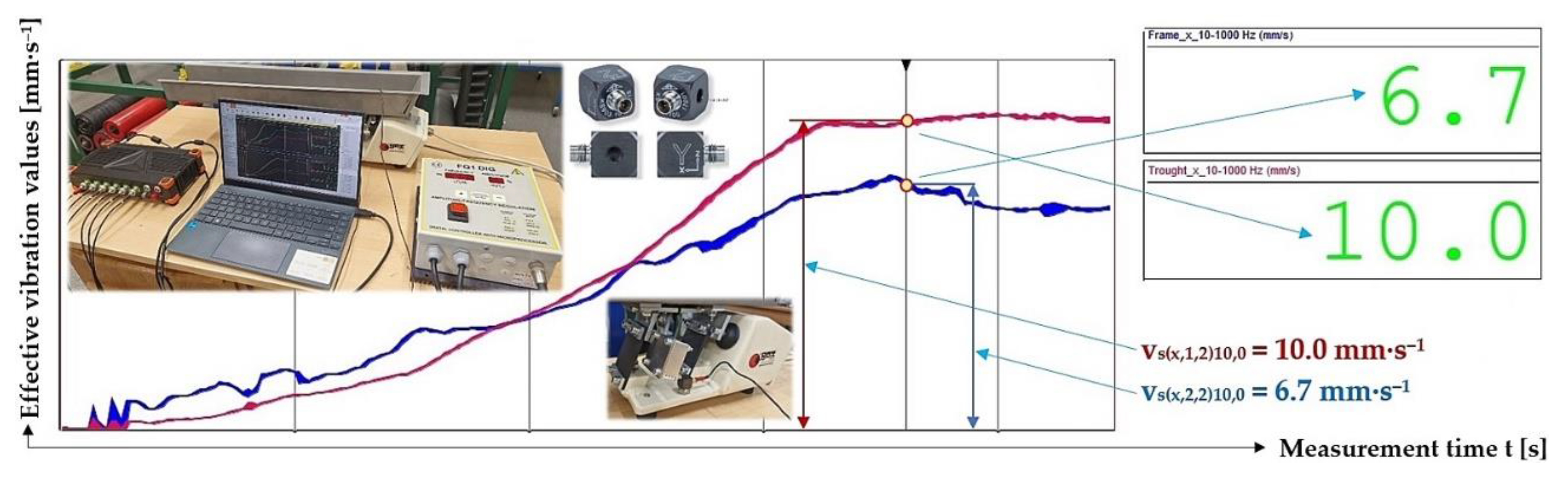
Figure 19.
Measured values of the effective vibration velocity vs(x,i,2)20,2.57 [mm·s‒1] in the direction of the x-axis of the trough (supported by 2 Steel leaf springs) and the steel frame of the vibrating feeder.
Figure 19.
Measured values of the effective vibration velocity vs(x,i,2)20,2.57 [mm·s‒1] in the direction of the x-axis of the trough (supported by 2 Steel leaf springs) and the steel frame of the vibrating feeder.
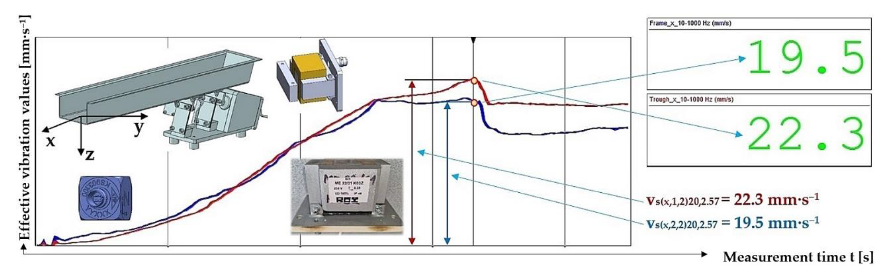
Figure 20.
Measured values of the effective vibration velocity vs(x,i,2)30,5.099 [mm·s‒1] in the direction of the x-axis of the trough (supported by 2 Steel leaf springs) and the steel frame of the vibrating feeder.
Figure 20.
Measured values of the effective vibration velocity vs(x,i,2)30,5.099 [mm·s‒1] in the direction of the x-axis of the trough (supported by 2 Steel leaf springs) and the steel frame of the vibrating feeder.
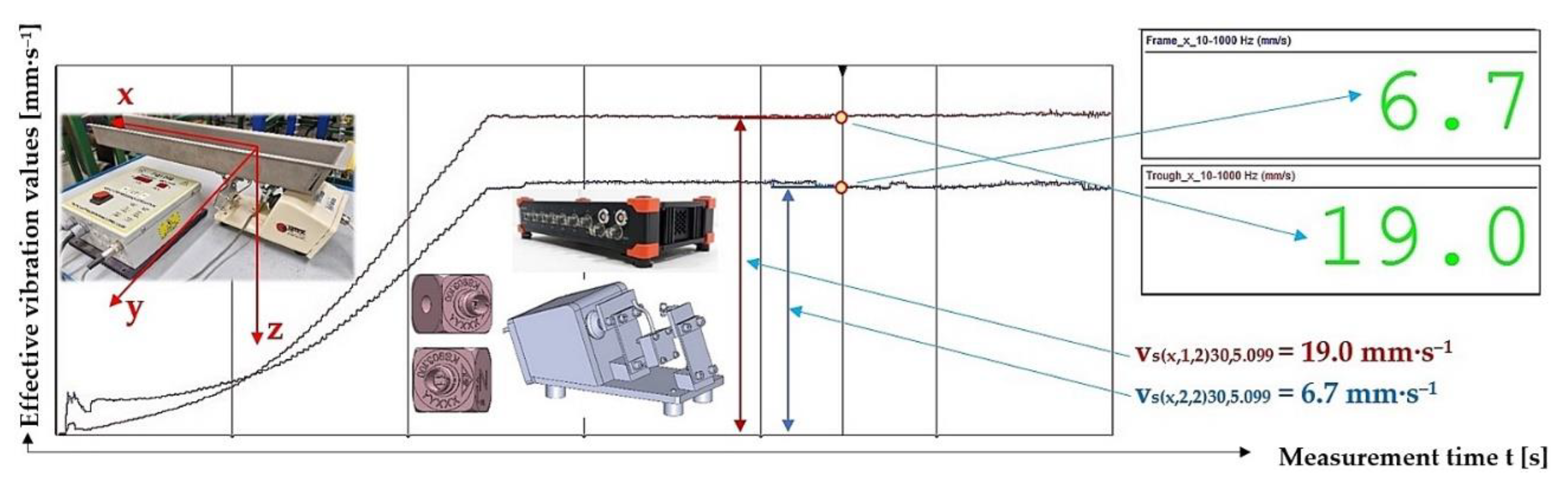
Figure 21.
Measured values of the effective vibration velocities vc(x,i,j)k,m [mm·s‒1] of the oscillation of the steel frame (continuous curve) and trough (dashed curve) of the vibrating feeder with various values of k [%] and the selected material of the leaf springs FR4 Epoxy.
Figure 21.
Measured values of the effective vibration velocities vc(x,i,j)k,m [mm·s‒1] of the oscillation of the steel frame (continuous curve) and trough (dashed curve) of the vibrating feeder with various values of k [%] and the selected material of the leaf springs FR4 Epoxy.
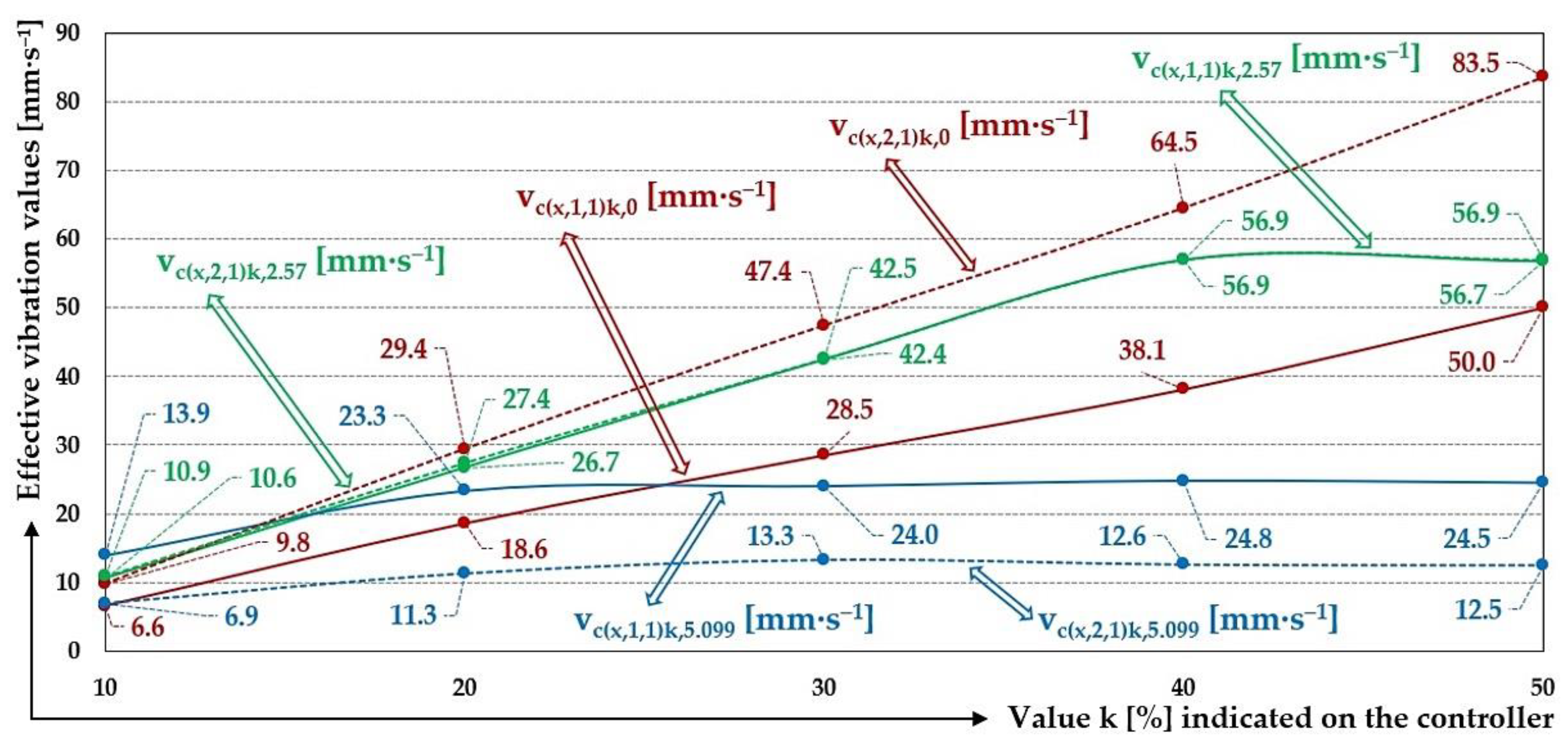
Figure 22.
Measured values of the effective vibration velocities vs(x,i,j)k,m [mm·s‒1] of the oscillation of the steel frame (continuous curve) and trough (dashed curve) of the vibrating feeder with various values of k [%] and the selected material of the leaf springs Steel.
Figure 22.
Measured values of the effective vibration velocities vs(x,i,j)k,m [mm·s‒1] of the oscillation of the steel frame (continuous curve) and trough (dashed curve) of the vibrating feeder with various values of k [%] and the selected material of the leaf springs Steel.
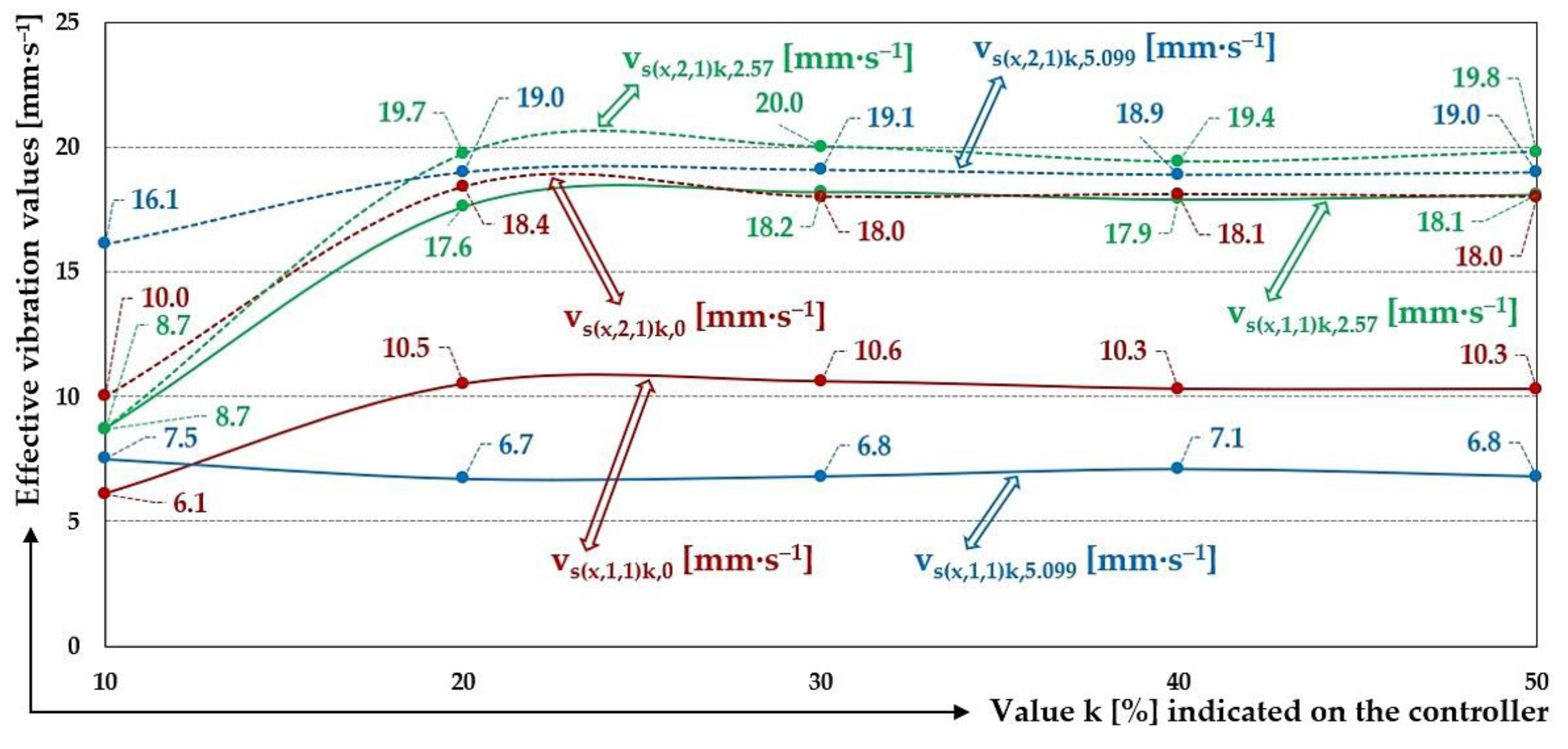
Figure 23.
Measured values of the effective vibration velocities vp(x,i,j)k,m [mm·s‒1] of the oscillation of the steel frame (continuous curve) and trough (dashed curve) of the vibrating feeder with various values of k [%] and the selected material of the leaf springs Plastic PCCF.
Figure 23.
Measured values of the effective vibration velocities vp(x,i,j)k,m [mm·s‒1] of the oscillation of the steel frame (continuous curve) and trough (dashed curve) of the vibrating feeder with various values of k [%] and the selected material of the leaf springs Plastic PCCF.
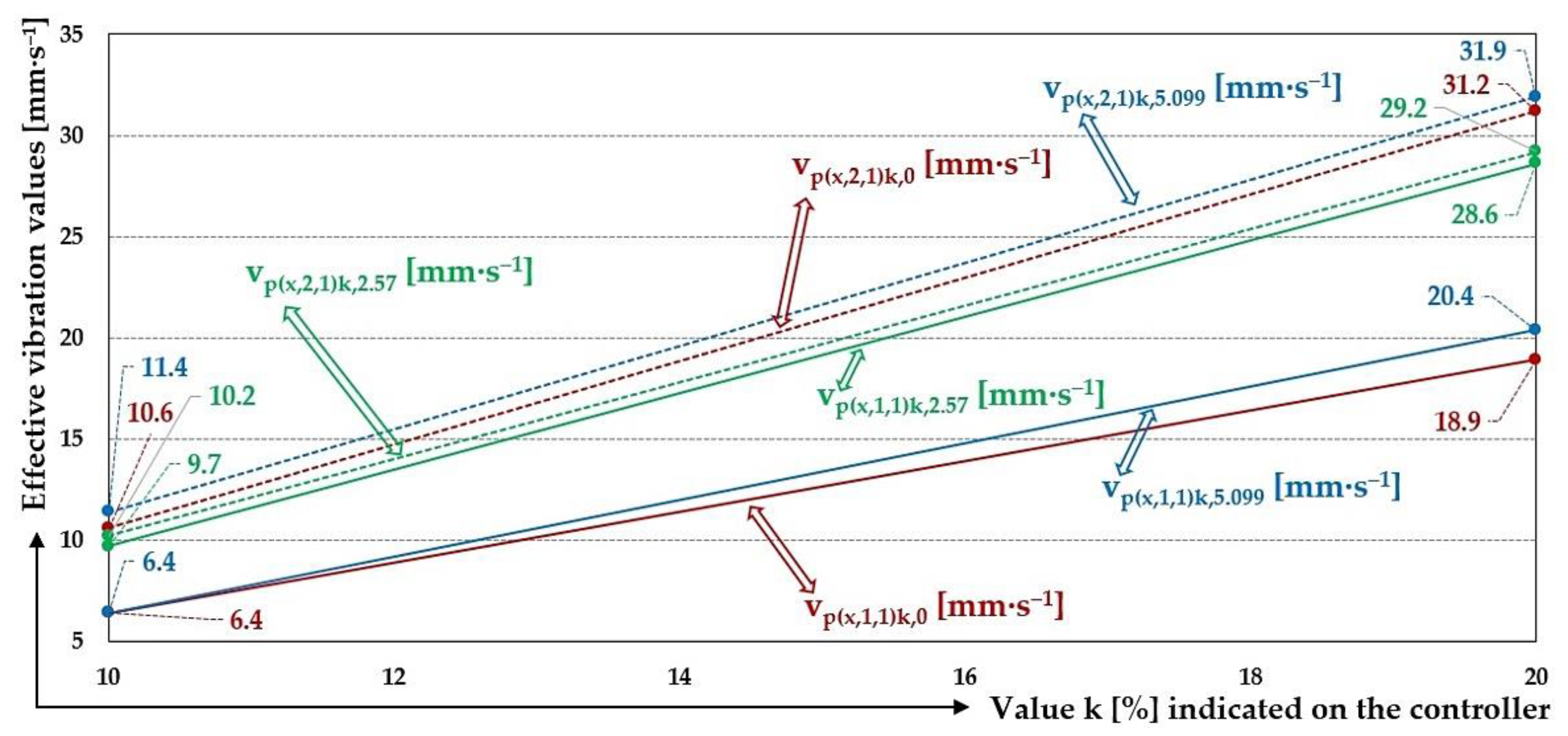
Table 9.
Effective vibration velocities vc(x,i,j)k,0 [mm·s–1] of the steel frame (i = 1) and trough (i = 2) measured in the "x" axis (l = x) of the coordinate system. Load weight m = 0 kg, leaf spring material FR4 Epoxy (∗ = c).
Table 9.
Effective vibration velocities vc(x,i,j)k,0 [mm·s–1] of the steel frame (i = 1) and trough (i = 2) measured in the "x" axis (l = x) of the coordinate system. Load weight m = 0 kg, leaf spring material FR4 Epoxy (∗ = c).
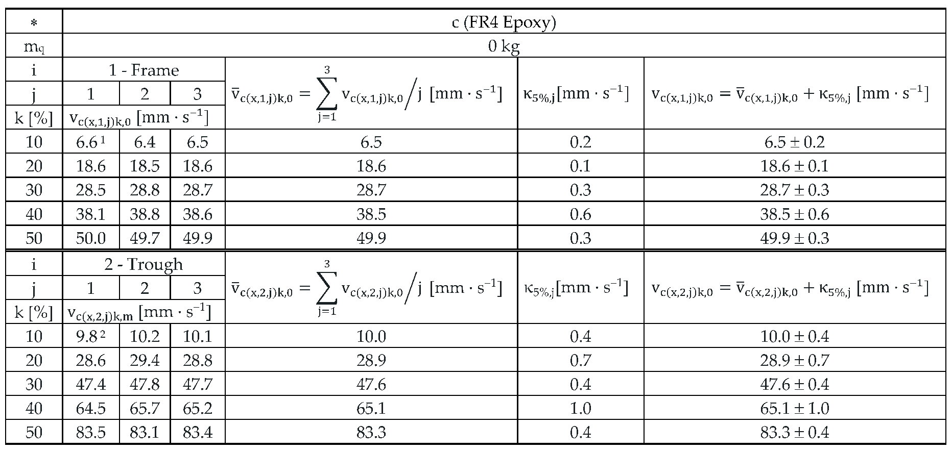 |
Table 10.
Effective vibration velocities vc(x,i,j)k,2.57 [mm·s–1] of the steel frame (i = 1) and trough (i = 2) measured in the "x" axis of the coordinate system. Load weight m = 2.57 kg, leaf spring material FR4 Epoxy (∗ = c).
Table 10.
Effective vibration velocities vc(x,i,j)k,2.57 [mm·s–1] of the steel frame (i = 1) and trough (i = 2) measured in the "x" axis of the coordinate system. Load weight m = 2.57 kg, leaf spring material FR4 Epoxy (∗ = c).
 |
1 see Figure 16.
Table 11.
Effective vibration velocities vc(x,i,j)k,5.099 [mm·s‒1] of the steel frame (i = 1) and trough (i = 2) measured in the "x" axis of the coordinate system. Load weight m = 5.099 kg, leaf spring material FR4 Epoxy (∗ = c).
Table 11.
Effective vibration velocities vc(x,i,j)k,5.099 [mm·s‒1] of the steel frame (i = 1) and trough (i = 2) measured in the "x" axis of the coordinate system. Load weight m = 5.099 kg, leaf spring material FR4 Epoxy (∗ = c).
 |
1 see Figure 17.
Table 12.
Effective vibration velocities vs(x,i,j)k,0 [mm·s‒1] of the steel frame (i = 1) and trough (i = 2) measured in the "x" axis (l = x) of the coordinate system. Load weight m = 0 kg, leaf spring material Steel (∗ = s).
Table 12.
Effective vibration velocities vs(x,i,j)k,0 [mm·s‒1] of the steel frame (i = 1) and trough (i = 2) measured in the "x" axis (l = x) of the coordinate system. Load weight m = 0 kg, leaf spring material Steel (∗ = s).
 |
1 see Figure 18.
Table 13.
Effective vibration velocities vs(x,i,j)k,2.57 [mm·s‒1] of the steel frame (i = 1) and trough (i = 2) measured in the "x" axis (l = x) of the coordinate system. Load weight m = 2.57 kg, leaf spring material Steel (∗ = s).
Table 13.
Effective vibration velocities vs(x,i,j)k,2.57 [mm·s‒1] of the steel frame (i = 1) and trough (i = 2) measured in the "x" axis (l = x) of the coordinate system. Load weight m = 2.57 kg, leaf spring material Steel (∗ = s).
 |
1 see Figure 19.
Table 14.
Effective vibration velocities vs(x,i,j)k,5.099 [mm·s‒1] of the steel frame (i = 1) and trough (i = 2) measured in the "x" axis (l = x) of the coordinate system. Load weight m = 5.099 kg, leaf spring material Steel (∗ = s).
Table 14.
Effective vibration velocities vs(x,i,j)k,5.099 [mm·s‒1] of the steel frame (i = 1) and trough (i = 2) measured in the "x" axis (l = x) of the coordinate system. Load weight m = 5.099 kg, leaf spring material Steel (∗ = s).
 |
1 see Figure 20.
Table 16.
Effective vibration velocities vp(x,i,j)k,2.57 [mm·s‒1] of the steel frame (i = 1) and trough (i = 2) measured in the "x" axis (l = x) of the coordinate system. Load weight m = 2.57 kg, leaf spring material Plastic (∗ = p).
Table 16.
Effective vibration velocities vp(x,i,j)k,2.57 [mm·s‒1] of the steel frame (i = 1) and trough (i = 2) measured in the "x" axis (l = x) of the coordinate system. Load weight m = 2.57 kg, leaf spring material Plastic (∗ = p).
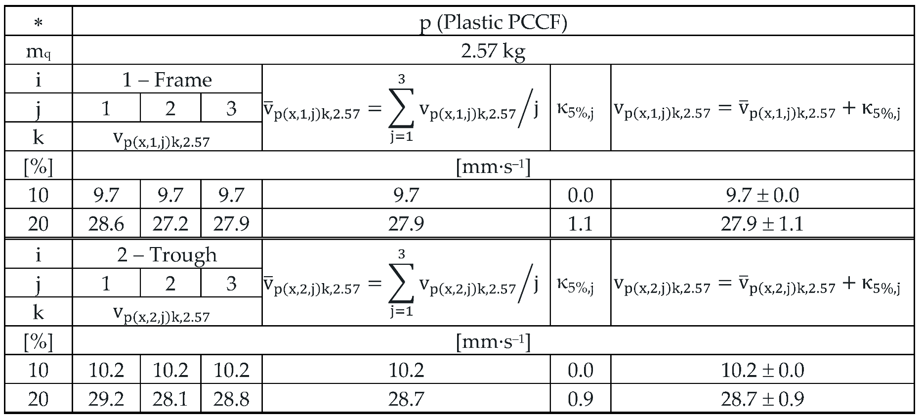 |
Table 17.
Effective vibration velocities vp(x,i,j)k,5.099 [mm·s‒1] of the steel frame (i = 1) and trough (i = 2) measured in the "x" axis (l = x) of the coordinate system. Load weight m = 5.099 kg, leaf spring material Plastic (∗ = p).
Table 17.
Effective vibration velocities vp(x,i,j)k,5.099 [mm·s‒1] of the steel frame (i = 1) and trough (i = 2) measured in the "x" axis (l = x) of the coordinate system. Load weight m = 5.099 kg, leaf spring material Plastic (∗ = p).
 |
Disclaimer/Publisher’s Note: The statements, opinions and data contained in all publications are solely those of the individual author(s) and contributor(s) and not of MDPI and/or the editor(s). MDPI and/or the editor(s) disclaim responsibility for any injury to people or property resulting from any ideas, methods, instructions or products referred to in the content. |
© 2025 by the authors. Licensee MDPI, Basel, Switzerland. This article is an open access article distributed under the terms and conditions of the Creative Commons Attribution (CC BY) license (http://creativecommons.org/licenses/by/4.0/).
Copyright: This open access article is published under a Creative Commons CC BY 4.0 license, which permit the free download, distribution, and reuse, provided that the author and preprint are cited in any reuse.


