
Submitted:
07 July 2025
Posted:
08 July 2025
You are already at the latest version
Abstract
Autonomous vehicles (AVs) are transforming transportation by improving safety, efficiency, and intelligence through integrated sensing, computing, and communication technologies. However, their growing reliance on Vehicle-to-Everything (V2X) communication exposes them to cybersecurity vulnerabilities, particularly at the physical layer. Among these, jamming attacks represent a critical threat by disrupting wireless channels and compromising message delivery, severely impacting vehicle coordination and safety. This work investigates the robustness of New Radio (NR)-V2X-enabled vehicular systems under jamming conditions through a dual-methodology approach. First, two Cooperative Intelligent Transport System (C-ITS) scenarios standardized by 3GPP—Do Not Pass Warning (DNPW) and Intersection Movement Assist (IMA)—are implemented in the OMNeT++ simulation environment using Simu5G, Veins, and SUMO. The simulations incorporate four types of jamming strategies and evaluate their impact on key metrics such as packet loss, signal quality, inter-vehicle spacing, and collision risk. Second, a complementary laboratory experiment is conducted using AnaPico vector signal generators (a Keysight Technologies brand) and an Anritsu multi-channel spectrum receiver, replicating controlled wireless conditions to validate the degradation effects observed in the simulation. The findings reveal that jamming severely undermines communication reliability in NR-V2X systems, both in simulation and in practice. These findings highlight the urgent need for resilient NR-V2X protocols and countermeasures to ensure the integrity of cooperative autonomous systems in adversarial environments.
Keywords:
NR-V2X
; jamming
; cooperative ITS
; vehicular communication
; cybersecurity
; experimental validation
1. Introduction
Autonomous vehicles (AVs) represent a transformative and promising field of innovation within the automotive and technology industries. By integrating advanced sensing, computation, and control systems, these vehicles can perceive their surroundings, plan routes, and execute driving actions while interacting with human operators when necessary [1]. As a result, AVs are at the forefront of a paradigm shift in transportation, offering a path toward safer, more efficient, and more sustainable mobility systems that can positively influence various sectors of society.
In urban environments, autonomous mobility has the potential to mitigate several longstanding challenges. The deployment of AVs may reduce traffic congestion, optimize travel times, lower fuel consumption and emissions, minimize the need for private vehicle ownership, and significantly decrease the number of road accidents [2]. However, achieving these benefits requires substantial technological infrastructure and continuous communication, data processing, and advancements in computational resources. To operate reliably in complex and dynamic traffic scenarios, AVs are becoming increasingly reliant on modern communication technologies such as edge computing, data-driven 5G traffic-forecasting mechanisms [3], Vehicle-to-Everything (V2X) connectivity, and emerging modular reconfigurable intelligent surfaces that can shape the radio environment [4,5,6].
Among the many enabling technologies, intravehicular networks play a central role by interconnecting electronic control units and sensors to coordinate various subsystems and ensure synchronized vehicular behavior [7]. These networks enhance situational awareness by fusing data from multiple sources—and, with RIS-aided visible-light links, can restore line-of-sight in obstructed urban scenarios [8]—leading to faster, more robust decision-making. However, the growing integration of AVs with interconnected systems also expands their attack surface, exposing them to a wide range of cybersecurity threats [9]. In particular, jamming and spoofing attacks have emerged as two critical concerns. Jamming attacks disrupt wireless communication by injecting interference into the radio spectrum, potentially compromising message delivery and endangering real-time decision-making [10]. This challenge has motivated adaptive DoA-aware beamforming counter-measures [11], as well as low-complexity broadband array processing and frequency-invariant beamforming schemes to suppress interference in V2X links [12,13]. Spoofing, conversely, involves impersonating legitimate nodes in the network to inject false data, leading to dangerous misinformation that can misguide autonomous control systems [14]. These threats are particularly severe in V2X communication contexts, where real-time message exchange between vehicles, infrastructure, and pedestrians is vital for safety and coordination.
A reliable communication infrastructure is essential to support the increasing demands of autonomous and connected mobility. Among the most prominent enablers is Vehicle-to-Everything (V2X) communication, a rapidly growing field that aims to improve the efficiency, safety, and scalability of transportation systems through direct interaction among vehicles, infrastructure, pedestrians, and the broader network [15]. V2X technologies support autonomous driving and enable applications such as cooperative maneuvers, intersection management, and safety messaging. Two primary approaches to V2X have gained traction: Dedicated Short-Range Communications (DSRC) and Cellular Vehicle-to-Everything (C-V2X). DSRC is a WLAN-based protocol built on the IEEE 802.11p standard and part of the Wireless Access in Vehicular Environments architecture. It operates in the 5.9 GHz spectrum, which was allocated by the Federal Communications Commission (FCC) in 1999 for exclusive use in vehicular communication. While DSRC has played a pivotal role in early Intelligent Transportation System (ITS) deployments, its range, latency, and scalability limitations have prompted the search for more robust alternatives.
C-V2X has emerged as a compelling successor, leveraging cellular infrastructure to support low-latency, high-throughput communication across multiple topologies, including Vehicle-to-Vehicle (V2V), Vehicle-to-Infrastructure (V2I), Vehicle-to-Network (V2N), and Vehicle-to-Pedestrian (V2P) [16,17]. With the advent of 5G, the New Radio V2X (NR-V2X) standard has been introduced to complement and eventually surpass LTE-V2X. This coexistence promises enhanced support for advanced use cases such as remote driving, platooning, extended sensor sharing, and ultra-reliable low-latency communication [18,19]. As vehicular communication ecosystems evolve toward more integrated, high-speed, and mission-critical environments, the security and resilience of V2X infrastructures become increasingly vital. This work emphasizes NR-V2X as a focal point for understanding the strengths and vulnerabilities of next-generation vehicular networks, particularly in the face of emerging cybersecurity threats.
Despite the rapid development of NR-V2X communication technologies and the deployment of increasingly sophisticated vehicular systems, ensuring cybersecurity resilience remains a critical challenge. The dynamic, decentralized, and real-time nature of V2X environments creates unique vulnerabilities, especially at the physical and communication protocol layers. Jamming [20] and spoofing [14] attacks can severely compromise vehicular safety by disrupting message exchange or injecting misleading data, posing risks to individual vehicles and the entire traffic ecosystem. While the literature thoroughly maps the threat landscape [21], many proposed defense mechanisms remain limited in scope, lack adaptability to dynamic environments, or have not been extensively evaluated under realistic, multi-agent traffic conditions. Moreover, there is a notable lack of simulation-based studies that model and compare the effects of different attack types across varying traffic coordination scenarios, although recent Beyond-5G virtual testbeds [22] and comprehensive reviews of security-oriented V2X simulators [23] begin to address this gap. This shortage of holistic evaluations hinders the design of robust, proactive cybersecurity strategies tailored to the specific demands of C-V2X networks.
To address the aforementioned challenges, this paper combines large–scale simulation and controlled laboratory experimentation to investigate jamming threats in NR-V2X vehicular networks. The specific contributions are:
- Attack-aware V2X scenarios. Two safety-critical Cooperative-ITS use cases—Do Not Pass Warning (DNPW) and Intersection Movement Assist (IMA)—are modeled in detail. Each scenario is extended to include an adversary that injects intentional Radio Frequency (RF) interference while vehicles perform standard maneuvers.
- Modular jamming framework for OMNeT++/Simu5G. We introduce reusable classes implementing NR-V2X PHY/MAC operation and four representative jamming strategies (constant, reactive, deceptive, and random). The code is fully integrated with Veins and SUMO, enabling repeatable network and mobility co-simulation.
- Comprehensive simulation assessment. The impact of the above jamming types on latency, packet-error probability, inter-vehicle spacing, and collision risk is quantified for both DNPW and IMA, revealing the most disruptive attack patterns and their dependence on traffic dynamics.
- Hardware-in-the-loop validation. A laboratory testbed—comprising one AnaPico APVSG40-4 signal generator (featuring four independent RF outputs), one dedicated jamming generator, and a four-channel Anritsu MS27201A receiver array—was built to replicate the wireless conditions used in the simulation. Measured degradation in constellation quality, Error Vector Magnitude (EVM), and message intelligibility corroborates the simulation findings.
- Design insights for resilient NR-V2X. By cross-analyzing simulation and experimental results, we identify parameter ranges (e.g., jammer bandwidth and power) that critically affect system performance and outline countermeasures that can be incorporated into future V2X protocol and detector designs.
The remainder of this paper is organized as follows: Section 2 presents the state of the art on V2X communication threats, focusing on jamming and spoofing attacks. Section 3 introduces the simulation study, including the modeled scenarios, the proposed solution, and implementation details using OMNeT++. It also discusses the simulation results for two critical Cooperative Intelligent Transport System (C-ITS) applications: DNPW and IMA. Section 4 details the laboratory experiments, describing the hardware setup, the experimental scenarios with and without jamming, and the corresponding results. Finally, Section 5 concludes the paper and outlines directions for future work.
2. State of the Art
A study performed by [24] experimented with an eavesdropper and jamming scenario to disrupt and monitor communication. Their approach focused on mitigating the invasion signal based on Deep Q-Networks (DQN) to select signal channels and intensity dynamically. The proposed approach can be applied in vehicular networks to reinforce system security. The two distinct attack types described in this scenario act concurrently to deteriorate the signal quality, impacting the Signal-to-Interference-plus-Noise Ratio (SINR) of vehicles connected to the network. This concerns both the operational and privacy aspects of the network, such as denying the service through communication failure and breaching private data. The research concluded that the jammers significantly impacted communication and the precision of location estimation, compromising the safety of vehicular operation.
Another study [25] explores power control and rate adaptation, two intrinsic functions of the physical layer, aiming to mitigate jamming effects in the internal 802.11 network. Rate adaptation provides a dynamic channel selection based on the condition of the channel, and power control adjusts the transmission power to fit a desired signal quality standard. This scenario included a random jamming attack pattern, in which the disrupting signal transmission does not follow a predictable pattern, composing a challenging attack pattern to overcome since it may saturate the channels with interference. The jamming operates using the user datagram protocol, allowing the scheduling of consecutive transmissions and cyclically alternating the state from active to idle. The Anti-jamming Reinforcement System (ARES) was conceived to mitigate the effects of the jammer by enhancing the parameters of transmission power and adaptive rate to operate in adversarial scenarios. The research results highlight the capabilities of ARES to adapt to different adversarial contexts, increasing the reliability and usability of the network.
Apart from ARES, which is explicitly focused on 802.11p networks, other frameworks were proposed aiming for a higher level of integration and device connection for traffic-denominated V2X [26]. One example is Generalized Dynamic Bayesian Networks (GDBNs) and Modified Markov Jump Particle Filter (M-MJPF), which are focused on tracking signals and predicting their behavior precisely. By comparing the tracked signals and predicted signal behavior, it is possible to detect the presence of a jammer through a classifier. Other approaches were proposed according to [27], where the Graham Scan Hull Algorithm (GSHA) and Centroid Localization are applied to detect and localize a jamming vehicle in a moving traffic scenario. This scenario assumes that traffic follows a platooning pattern with restricted position changes to maintain the platooning area constant. Vulnerabilities are present both on the physical layer and the Media Access Control (MAC) of a 5G C-V2X communication system [28]. Research was conducted to identify the eventual threats and evaluate attack severity through experimentation. The main idea is not only to disturb the physical and operational quality of the network but also to target resources, delivering a denial of service by exhausting resources capabilities. The conducted attack types focus on breaching from the physical layer by performing scheduled transmission interval-based algorithms such as Semi-Persistent Scheduling (SPS). The scenario studied by [29] represents a targeted attack, requiring the attacker to identify the target message reception schedule and channel and interfere by generating a disrupting signal synchronized with the scheduled Basic Safety Message received frequency of the target. Finally, solutions are proposed to diminish the vulnerabilities and effects of the attacks by exploring NR-V2X functions to schedule non-periodical transmissions and reduce the listening window of SPS.
5G C-V2X networks are an emerging technology field commonly adopted for vehicular networks [30]. The exchange of safety messages is crucial to avoid accidents in traffic and the development of Intelligent Transport Systems (ITS), which requires well-planned security solutions leveraging millimetric wavelength spectrum (mmWave) C-V2X. The resources and strategies of C-V2X are defined by the 3rd Generation Partnership Project (3GPP). Machine Learning techniques are also explored to detect and neutralize attacks targeting C-V2X networks. The article from [31] describes an attack in which a RF signal generator is used to attack the physical layer of the system. The attacker works as a spoofer, manipulating data to be interpreted as a legitimate package transmitting false readings of sensors like Global Navigation Satellite System (GNSS) and Inertial Measurement Unit (IMU) through BSMs. This type of attack is called phantom cars. A complex framework is proposed to deny the interference from such kind of attack, including base station integration and data fusion to classify false information propagation. Essential parameters are defined to simulate these scenarios, from V2V transmission power to carrier frequency for V2V and V2I communication. The frequency bandwidth utilized in this C-V2X scenario presented a range from 2 to 73.5 GHz for Urban Microcellular Street Canyon (UMiSC) and Urban Macrocellular (UMa) while presenting a 2 to 60 GHz for Urban Microcellular Open Square (UMiOS). Countermeasures proposed for the problem mentioned above highlight the use of the Received Signal Strength Indicator (RSSI) and Time Difference of Arrival (TDOA) alongside hybrid implementations that fuse these techniques to reach peak performance in detecting these challenging attacks.
Another introduction to the field of autonomous vehicles and interconnected traffic is the concept of Connected Vehicles (CV), composing the ecosystem of Traffic Signal Control (TSC) environments [32]. Safety and Mobility are greatly improved by adopting connectivity between vehicles and infrastructure to maintain a continuous connection topology. However, this also introduces new liabilities and vulnerabilities to cybernetic threats. A two-stage scenario is developed to analyze the overall structure of C-V2X against cybernetic attacks comprehensively. Like previously presented attack techniques, the Intelligent Signal (I-SIG) system is monitored and observed to determine a model that simulates the legitimate control patterns and information transmission to finally provide falsified data to bias the control system into taking suboptimal control decisions. I-SIG is vulnerable to Estimated Time of Arrival (ETA) attacks and phantom queues. I-SIG uses the ETAs table to evaluate delay, while phantom queues aim to estimate the traffic state under lower CV density levels. The conducted research concludes that these attacks impact traffic performance by significantly increasing the operational delay and the efficiency of defense models to detect and filter illegitimate data.
Different attack detection methodologies are proposed, including traffic infrastructure resources, to increase the reliability of data legitimacy by performing a cross-validation analysis of traffic state [33,34]. Algorithms like Multi-Sensor Fusion (MSF) improve the detection of anomalies by fusing information from multiple available sources, providing weighted decision-making considering a clustered representation and reconstruction of sensor data.
3. Simulation Study
This section presents the simulation-based investigation conducted to assess the impact of jamming attacks on cooperative vehicular communication. Two C-ITS use cases standardized by 3GPP—DNPW and IMA—are modeled using the Simu5G environment. Each scenario is first simulated under normal operating conditions and then extended to include a jamming component. Key communication metrics, such as signal quality and packet loss rate, are evaluated concerning inter-vehicle distance and potential interference in D2D communication.
Section 3.1 introduces the simulation scenarios and explains their relevance in safety-critical traffic contexts. Section 3.2 describes the simulation framework, including the integration of tools and the class-level implementation in OMNeT++. Section 3.3 presents and analyzes the results obtained in both use cases under clean and jammed communication conditions.
3.1. Simulation Scenarios
This subsection presents the two simulated scenarios designed to evaluate the impact of jamming attacks on cooperative vehicular applications. Section 3.1.1 models a high-risk overtaking situation, where timely communication is essential to avoid head-on collisions. Section 3.1.2 simulates a complex intersection with precedence rules, where the receiver vehicle must interpret transmissions from multiple directions. In both cases, a jammer is introduced to evaluate how intentional interference affects safety-critical decision-making in standardized C-ITS environments.
3.1.1. Scenario 1: DNPW
The DNPW scenario, presented in Figure 1, describes a scene in which a receiver vehicle has the intention of passing through the counter lane of the Transmitter 1 vehicle that is moving in the same direction at a lower speed while at the exact moment the Transmitter 2 vehicle approaches in the opposite direction. The goal of the transmitters is to inform the receiver about their current kinematics parameters; the receiver, on the other hand, must act accordingly with the obtained data to maintain safety and avoid collision.
A jammer unit is added to the scene with the objective of interrupting the communication between the transmitters (Tx) and the receiver (Rx), representing the attacker. The success of the jammer disruption signal should disable the communication between the vehicles or degrade the signal in a scale that communication occurs at a slower rate due to packet loss, possibly causing an accident. DNPW is a typical vehicular use case that is standardized by 3GPP in the field of autonomous vehicles.
3.1.2. Scenario 2: IMA
The IMA environment scenario, presented in Figure 2, is composed once again of three vehicles. However, instead of performing a passing movement, the receiver vehicle is performing a turn in a crossing. The direction of the transmitters is perpendicular to the receiver’s trajectory when incoming the crossing, and the order of preference must be obeyed. The receiver will turn in the same direction as the incoming transmitter, which is the first in the order of precedence, and should wait until the turning is available before proceeding, while the other transmitter is the last in the order of precedence.
The jammer unit is introduced spatially close to the crossing once again to interfere with the communication between transmitters and receiver, aiming to block the exchange of kinematics information between them. The disturbance in information flow might generate insufficient spatial resolution for the receiver vehicle to detect the other incoming cars and cause a collision due to wrong precedence inference. The 3GPP standardizes the IMA operation scenario in the field of autonomous vehicles.
3.2. Simulation Framework
The structure of this simulation framework is organized into two main parts. Section 3.2.1 presents the integration of simulation tools—including OMNeT++, Simu5G, Veins, and SUMO—and explains how they collaborate to model vehicular networks under NR-V2X communication. Section 3.2.2 details the hierarchical design of the simulation modules, highlighting the role of customized components such as the NRCar and JammerNode and describing how NED files and C++ classes are used to define node behavior within the OMNeT++ environment.
3.2.1. Proposed Solution
This project was developed using the following simulation tools: OMNeT++, INET framework, Simu5G, Veins, and SUMO. Figure 3 illustrates how these tools are encapsulated and cooperate to create vehicle network simulations. Each component played a crucial role in the project, and definitions are provided below to help understand their contributions better. OMNeT++ is a modular, object-oriented discrete event simulator widely used for building network simulators. It allows for the flexible and scalable creation of network simulation models, enabling the analysis of various scenarios and communication protocols. The INET framework is a library within OMNeT++ containing models of major network and link layer protocols for wired and wireless networks. It also supports mobility, MANET protocols, DiffServ, MPLS with LDP and RSVP-TE signaling, and various application models.
Simu5G is a 5G NR network simulator based on the SimuLTE library created by the same research group. It is built upon the OMNeT++ simulation framework and offers a variety of well-defined interface models. These models can be instantiated and connected to create simulation scenarios of varying complexity. Simu5G incorporates INET library models, allowing for the simulation of generic TCP/IP networks. It supports Frequency Division Duplex (FDD) and Time Division Duplex (TDD) communication modes and various heterogeneous gNodeBs. The software also supports X2 interface communication to facilitate cell interference coordination and transition. Furthermore, Simu5G supports multiple mobility models for User Equipment (UE). It allows for the implementation of different resource allocation and management strategies, including the selection of target UEs, modulation scheme choice, coordination to minimize inter-cell interference, and frequency band selection.
Veins is an open-source vehicular network simulation framework that comes with a collection of vehicle communication simulation models. These models are designed to interact with a traffic simulator like SUMO to provide a bidirectionally coupled simulation of road traffic and network. SUMO is a detailed, multimodal, open-source road traffic simulator that simulates individual vehicle movements on a specific road network. Simulations are deterministic by default, but randomness can be introduced to the simulation agents. After defining the simulators used, it is crucial to understand how these modules integrate, as depicted in Figure 3 OMNeT++ acts as the central controller of the simulation and as the data collector. Within the OMNeT++ environment, Simu5G establishes connectivity among autonomous vehicle network nodes, simulating various layers and settings in 5G networks.
Veins and Simu5G are connected through a communication channel within the OMNeT++ environment to facilitate an autonomous vehicle network simulation. The connection allows the two simulators to exchange information and collaborate on simulating the behavior of the autonomous vehicle network. With the connection established between Veins and Simu5G, the Mobility module of the Veins plays a crucial role. It facilitates integration between Simu5G and SUMO by updating the mobility information of the node, such as position, speed, and direction, based on vehicle behavior. The interconnection between OMNeT++ and SUMO is established through a TCP socket, enabling communication via the Traffic Control Interface (TraCI) protocol.
Finally, it is noteworthy that simulating an autonomous vehicle network is not limited to just communication among nodes. Vehicle mobility, influenced by various factors such as traffic and road conditions, is also essential. These aspects are simulated by SUMO, which provides a simulation environment allowing vehicles to move according to implemented traffic conditions.
3.2.2. OMNeT++ Class Implementation
The OMNeT++ simulations are built on top of network descriptor files (NED files) that contain simple modules, modules, and networks, establishing parameters definition, gate connections, and behavior rules that are interpreted by C++ classes that encapsulate the NED files parameters through omnetpp.h API. The INET 4.5 library provides all the LTE and low-level network infrastructure abstraction standards and is available at the OMNeT++ Simulation Models interface. The Simu5G integrates the functions of 5G Networks, including the Cars module feature that simulates a vehicle using a user equipment inheritance. The Cars module introduces mobility parameters that allow the simulation of the kinematics of the car based on the Veins library, which is responsible for vehicular network features provision.
The Car package includes two modules, Car and NRCar. Both have a similar interface inherited from the UE module; the difference stands with the NRCard presenting New Radio (NR) capabilities from the 5G short-range communication standards. The Jammer Node has a different implementation from UE, working instead as a base station (eNodeB). The idea is that jammerNodes also generate and transmit a signal in the physical layer, operating in the same channels of NR communication. The overall hierarchical representation of the proposed classes can be described by the Unified Modeling Language (UML) class diagram displayed in Figure 4. The hierarchy consists of the NED files hierarchy rather than the C++ object derivation, which happens in the underlying layers of OMNeT++ compilation and simulation in runtime.
3.3. Simulation Results
This section presents the simulation results organized into six subsubsections. Section 3.3.1 describes the execution of the overtaking scenario and the potential communication risks. Section 3.3.2 examines the packet loss, SINR, and inter-vehicle distance under normal conditions. Section 3.3.3 analyzes the impact of periodic jamming on communication reliability. Section 3.3.4 introduces the intersection scenario and the communication logic involved. Section 3.3.5 presents the baseline metrics without interference. Finally, Section 3.3.6 evaluates how the jammer degrades signal quality and increases packet loss at critical decision points.
3.3.1. Simulation of the DNPW Scenario
In the execution of the DNPW scenario, implemented in the Simu5G simulator and illustrated in Figure 5, the potential trajectories are highlighted by red lines. The elements of the scenario include the first transmitting car (car[1]) and the second transmitting car (car[0]), which moves in the opposite direction to car[1]. Additionally, the scenario features the receiving car (car[2]), which follows in the same direction as the car[1]. The vehicle car[2] is in a critical situation, as the imminent possibility of lane changing could lead to an accident. Another critical component is the jammer, strategically located a few tens of meters away from the three vehicles. Its primary function is to cause electromagnetic interference, potentially negatively affecting packet reception in car[2] and causing communication failures between vehicles, significantly increasing the risk of accidents.
3.3.2. Parameters Analyzed in the DNPW Scenario
The parameters in the DNPW scenario without attack, measured between the nodes car[0] and car[2], are illustrated in the following figures. Figure 6(a) shows the packet loss rate over time. Figure 6(b) displays the SINR ratio, representing the signal quality received on the channel relative to noise and interference.
Furthermore, Figure 6(c) represents the distance between the nodes over time, providing more context for the analysis. At the beginning of the simulation, the significant distance—on the order of hundreds of meters—between car[0] and car[2] leads to a high packet loss rate, evidenced by low SINR values below the zero dBm threshold. As the vehicles gradually approach each other, the quality improves, and the packet loss rate begins to decrease. The peak quality occurs when the distance is minimal. Subsequently, the quality decreases as the vehicles move apart, and the packet loss rate increases.
The parameters in the DNPW scenario without an attack, measured between vehicles car[1] and car[2], are presented in Figure 7. At the beginning of the simulation, as shown in Figure 7(c), the vehicles are close together, resulting in low packet loss as depicted in Figure 7(a) and high signal reception quality in Figure 7(b). As the vehicles distance themselves from one another, the packet loss rate increases, and the quality fluctuates but generally decreases as the distance grows. It is important to note that the peak in packet loss rate, influenced by the proximity to the car[0], occurs between 15 s and 20 s. During this time interval, car[0] passes by car[1] and car[2], inducing cell interference in their communication.
3.3.3. Parameters Affected by the Attack in the DNPW Scenario
Periodic jamming was selected in the DNPW from among the types of attacks described in Appendix A. This choice is energy and hardware-efficient as the interference induced by the jammer occurs at regular intervals, alternating between periods of attack and periods of inactivity, thereby reducing resource consumption. Moreover, scheduling work cycles at opportune moments, as in the DNPW, enhances the effectiveness of the attack. The jamming attack was implemented in the time interval between 12s and 20s, coinciding with the opportune moment of vehicle approach, as evidenced in Figure 7(c). During this attack period, interference signals were sent every 100 ms to impair the receipt and processing of data packets in the vehicle car[2].
Figure 8 displays the packet loss rate between nodes car[0] and car[2], highlighting the attack interval represented by the red area. The data from scenarios without jamming interference are depicted in blue. Meanwhile, cases with an attack featuring jammers of the output power of 1W and 30W for each band are shown in orange and green, respectively. The packet loss rate increases during the attack in the specified interval. In the scenario without a jammer, the loss rate is lower. When a jammer with an output power of 1W per band is used, the loss rate intensifies and becomes even greater with a jammer of 30W per band. After the attack interval, the rates do not immediately decrease due to the discrepancy created by the attack between the number of packets transferred and received.
In terms of signal quality, Figure 9 illustrates the variation of SINR between vehicles car[0] and car[2]. Initially, the quality fluctuates around the zero dBm threshold due to the significant distance between the nodes. During the interval from 12 s to 20 s, owing to the proximity between the vehicles, the signal without a jammer results in quality well above the threshold. On the other hand, in the attack scenarios with a 1 W jammer, the quality is below the threshold, and in the case of a 30 W jammer, the quality decreases considerably. After the attack interval, as the vehicles distance themselves, the SINR ratio in the scenarios fluctuates.
The packet loss rate between vehicles car[1] and car[2] is shown in Figure 10, with the distance between the nodes being relatively close, as indicated in Figure 7(c). In this context, packet loss in the scenario without a jamming attack is minimal. However, during the attack interval highlighted in red, packet loss is significant in the case with the orange jammer and even greater in the green case, which has a higher output power. Immediately after the attack, packet losses in the green and orange cases tend to decrease, but not immediately, because of the attack.
In terms of signal quality between nodes car[1] and car[2], Figure 11 demonstrates that the proximity between the vehicles, in the case without jammer interference, results in a signal quality significantly above the SINR threshold of zero dBm. This quality reflects greater data transfer and reliability in communications between the CVs. However, the SINR ratio was compromised during the attack interval in the orange case and was further reduced in the green case, with a higher output power of the jammer.
3.3.4. Simulation of the IMA Scenario
The representation of the IMA scenario, conducted in Simu5G, is illustrated in Figure 12, with potential trajectories highlighted in red lines. The components of the scenario include the transmitting cars, car[1] and car[0], the latter moving in the opposite direction to the former. The scenario includes the receiving vehicle, the car[2], which moves from top to bottom to turn left at the intersection. All vehicles are in a risky situation, as car[0], car[1], and car[2] may be on collision courses. A crucial component is a jammer, strategically positioned and distant by tens of meters from the three vehicles. Its primary function is to generate electromagnetic interference, which can compromise packet reception by car[2]. This scenario presents a significant risk, as the interference can cause vehicle communication failures, increasing the likelihood of collisions.
3.3.5. Parameters Analyzed in the IMA Scenario
In the IMA use case, where no jamming attack occurs, the network parameters analyzed between nodes car[0] and car[2] are systematically detailed in the subsequent figures. Figure 13(a) illustrates the packet loss rate over time. Figure 13(b) displays the SINR ratio, which indicates the signal quality received on the channel compared to noise and interference. Moreover, Figure 13(c) shows the distance between the nodes over time, providing a complementary overview elucidating the analysis.
At the beginning of the simulation, the considerable distance between car[1] and car[2] results in a high packet loss rate, also reflected by the low quality with SINR values below the zero dBm threshold. As the vehicles approach each other, the signal quality improves, and the packet loss rate begins to decrease. The peak quality is achieved when the distance between the vehicles is minimal, indicating a correlation between distance and signal quality. However, as the cars begin to distance themselves, the quality of the signal declines, and the packet loss rate starts to increase again, reinforcing the crucial importance of vehicle proximity for effective communication.
In the IMA scenario without jamming interference, determined between vehicles car[1] and car[2], the parameters are depicted in Figure 14. At the start of the simulation, as seen in Figure 14(c), the vehicles are hundreds of meters apart, resulting in a high packet loss rate, as shown in Figure 14(a), and low signal quality, as indicated in Figure 14(b). As the vehicles draw closer, the initially high packet loss rate begins to decrease, as depicted in Figure 14(a). Concurrently, Figure 14(b) shows that the signal quality is initially low due to the distance between the vehicles but begins to improve significantly.
Ultimately, when vehicles car[1] and car[2] begin to move in the same direction, the signal quality remains high. The ongoing proximity between the vehicles facilitates efficient communication. Thus, keeping the cars close is key to optimizing signal quality and reducing packet loss rates.
3.3.6. Parameters Affected by the Attack in the IMA Scenario
The decision to implement periodic jamming attacks in the IMA scenario was made considering its characteristics. The interference caused by the jammer occurs at fixed intervals, alternating between attack periods and periods of inactivity, which can minimize resource use. Furthermore, the ability to schedule work cycles at strategic moments, such as in high-risk situations in the IMA, may increase the effectiveness of the jamming attack. The attack was implemented between 18 s and 26 s, aligning with the moment of closest proximity between the vehicles, as illustrated in Figure 13(c). During this attack period, interference signals were sent every 100 ms with the aim of impairing the reception of data packets in vehicle car[2].
Figure 15 shows the packet loss rate between nodes car[0] and car[2], with an emphasis on the attack period indicated by the red area. The data from scenarios without jamming interference are presented in blue. In contrast, in the IMA scenarios that were adapted to include an attack, the colors orange and green represent jammers with output powers of 1 W and 30 W per band, respectively. During the attack in the specified interval, there is an increase in the packet loss rate. The loss rate is lower in the scenario that does not use a jammer. Implementing a jammer with an output power of 1 W per band causes a significant increase in the loss rate, which is further amplified with a jammer of 30 W per band. After the end of the attack, the loss rates do not immediately return to their previous state due to the discrepancy caused by the attack between the number of packets sent and received.
Figure 16 highlights the change in the SINR ratio between vehicles car[0] and car[2], a crucial parameter for assessing signal quality in connected vehicle communication systems. At the beginning of the observation, the signal quality tends to fluctuate around the zero dBm threshold. This behavior is attributed to the considerable distance between the nodes. During the time interval from 18 s to 26 s, a notable change is attributed to the proximity between the vehicles. In this scenario, the signal quality is above the zero dBm threshold without a jammer. This fact underscores that proximity between nodes can positively impact signal quality, facilitating more effective communication between vehicles. However, in scenarios where an attack with a 1 W jammer occurs, the signal quality remains below the threshold most of the time. The signal quality decreases even further when the jammer has an output power of 30 W. After the end of the attack, as the vehicles distance themselves, the signal quality in the scenarios begins to vary and shows a trend of decline.
Figure 17 displays the packet loss rate between vehicles car[1] and car[2]. Initially, with the nodes distant, as indicated in Figure 14(c), the packet loss in the scenario without a jamming attack is high but decreases as the vehicles approach the intersection. During the attack interval, marked in red, the packet loss is considerable in the scenario with the orange jammer and even more intense in the green scenario, which has a higher output power. After the attack, the packet losses in the green and orange scenarios begin to decrease, but not immediately, reflecting the consequences of the attack.
Figure 18 shows the signal quality between nodes car[1] and car[2]. The considerable distance between the nodes initially results in a signal quality close to the SINR threshold of zero dBm. As the vehicles approach each other, the signal quality progressively improves. However, the signal quality is impacted during the attack interval, being more compromised in the orange case and even more so in the green case, where the jammer has a higher output power. After the attack interval, the vehicles remain close to each other, maintaining the high quality of the received signal.
4. Laboratory Experiments
This section presents a laboratory-based evaluation of jamming attacks on NR-V2X systems under static, line-of-sight conditions. The objective is to validate, in a controlled environment, the communication degradation mechanisms previously observed in simulation. To this end, a hardware-in-the-loop setup comprising multiple synchronized signal generators and receivers was developed. The experimental campaign was structured around two scenarios—with and without jamming—to isolate the impact of intentional interference on signal quality and message recoverability. Section 4.1 details the experimental setup, including the signal generation architecture and receiver array used to emulate and monitor V2X communication. Section 4.2 defines the two test conditions: one with clean signal transmission and another with deliberate RF interference introduced by a dedicated jammer. Finally, Section 4.3 analyzes the results, comparing baseline and jammed transmissions using modulation metrics, spectral characteristics, and message decoding outcomes to quantify performance degradation.
4.1. Experimental Setup
This subsection outlines the physical testbed developed to evaluate the impact of RF jamming on NR-V2X communication links under controlled conditions. Section 4.1.1 presents the multi-channel transmission and interference architecture, which consists of four data-bearing signal generators and a dedicated jamming source, each equipped with horn antennas to emulate V2X transmission patterns. Section 4.1.2 describes the corresponding reception and decoding system, which uses four synchronized Anritsu spectrum monitors to capture and analyze the transmitted signals. The entire setup is designed to maintain static line-of-sight conditions with tight synchronization across all channels, enabling accurate comparison between clean and jammed transmission environments.
4.1.1. Multi-Channel Transmitter and RF-Jamming Setup
The transmission front-end (Figure 19, Figure 20, and Figure 21) consists of five phase-coherent Vector Signal Generators (VSGs) from the AnaPico APVSG40 family (a subsidiary brand of Keysight Technologies).
- Data transmitters — One APVSG40-4 unit (10 MHz–40 GHz, four independent RF outputs each) was configured to transmit distinct, pre-encoded V2X-like data streams. All units were synchronized using a shared reference clock and trigger signal, ensuring channel phase coherence.
- Intentional jammer — A second generator (single-channel APVSG40, with red chassis) was used exclusively to emit controlled RF interference. During jamming trials, this unit injected wideband swept-frequency noise centered near the transmission band. Its output was routed to a spatially separated antenna positioned to interfere with line-of-sight reception.
Each data stream was delivered via a coaxial line to an ERAVANT® WR-28 conical horn antenna, forming a linear four-element array mounted on a custom metallic fixture. The structure ensures rigid spacing and boresight alignment, emulating a roadside unit with spatially distributed emitters. The jamming signal was transmitted from a fifth, elevated horn antenna, clearly visible in Fig. Figure 20, positioned laterally to induce additional multipath and angular interference.
The scenario was intentionally constrained to static, line-of-sight conditions, omitting Doppler and mobility effects to allow isolated evaluation of the jamming impact on multi-antenna decoding strategies. This setup enables comparative assessment between clean and degraded RF environments using the same physical geometry.
4.1.2. Receiver Array and Signal Decoding System
The reception and decoding stage is implemented using four synchronized Anritsu MS27201A Remote Spectrum Monitors, as shown in Figure 22 and also visible on the right side of Figure 20. Each unit operates as a broadband RF receiver capable of capturing time-resolved in-phase and quadrature (IQ) samples for post-processing. These instruments support remote control via networked Ethernet, with unique static IPs assigned to each module to allow coordinated data acquisition.
Each MS27201A is connected to a dedicated ERAVANT WR-28 conical horn antenna, identical to those used in the transmission stage, aligned and fixed on a metallic support aligned with the transmitter array. Four receivers allow spatial sampling of the incident RF wavefront, enabling evaluation of multi-channel decoding performance under intentional interference.
The received signals, perturbed by the jamming source described in Section 4.1.1, are captured in parallel and stored for subsequent decoding and performance analysis. All equipment was configured to maintain time alignment between channels, ensuring consistent relative phase during reception. The receiver array mimics a stationary roadside unit or vehicle node equipped with four directional RF front-ends operating in a jammed V2X environment.
4.2. Experiment Scenarios
Two distinct experimental scenarios were defined to evaluate the impact of intentional interference on the decoding performance of the receiver array:
- Scenario 1 — Clean Transmission: Only the four data-bearing transmitters were active in this baseline configuration. Each signal was modulated and transmitted via its corresponding ERAVANT horn antenna without any intentional external disturbance. This scenario serves as a reference for ideal reception conditions.
- Scenario 2 — Jamming Condition: In addition to the four transmitters, the jamming unit (described in Section 4.1.1) was activated. The interfering signal, emitted from a separate antenna with lateral offset, introduced controlled RF noise into the system. The jammer was active throughout the signal transmission and reception period.
In both scenarios, the same set of messages was transmitted and received under otherwise identical physical and electrical conditions. This design isolates the effect of the jammer on decoding performance, enabling direct comparison between clean and degraded RF environments.
4.3. Experimental Results
This subsection presents the outcomes of the laboratory experiments designed to assess the effect of jamming on static NR-V2X communication links. Section 4.3.1 establishes a baseline by analyzing the transmission quality in the absence of interference, characterizing modulation performance using constellation diagrams, eye patterns, and spectral analysis. In contrast, Section 4.3.2 introduces a controlled co-channel jammer to evaluate how interference impacts signal fidelity and decoding reliability. The comparison between both scenarios offers practical insight into the degradation mechanisms caused by intentional RF disruptions in a controlled setting.
4.3.1. Baseline Case: Transmission Without Jamming
In the first experimental condition, the four data-bearing transmitters were activated without any interfering signal present in the environment. The goal was establishing a reference for clean transmission and reception performance under static line-of-sight (LoS) conditions.
The message content was defined as: "You are participating in the B5GCyberTestV2X Project Closing Meeting." This message was converted to binary and modulated using QPSK. A preamble was prepared to support synchronization at the receiver side. The resulting waveform was shaped by a transmit filter and stored in a complex-valued IQ file, as illustrated in Figure 23. This file was then uploaded to the VSGs.
IQ samples were captured using the Anritsu MS27201A spectrum monitors and processed offline at the receiver side. Figure 24 shows a representative screenshot of the RF signal analysis software connected to one of the receivers. The signal exhibits a clean spectral footprint, open-eye diagrams for both I and Q components, and a well-defined QPSK constellation. Modulation quality indicators, such as EVM and MER, confirm low-noise reception.
Figure 25 highlights the symbol constellation before and after transmission. The red plot (TX) shows the ideal transmitted symbols, while the green plot (RX) displays the received samples. Despite minor dispersion, the four QPSK clusters are clearly preserved, indicating accurate demodulation.
In Figure 26, a comparison between the real-time spectrum (blue) and post-processed signal (yellow) confirms spectral alignment and consistency across acquisition stages. No out-of-band interference or spectral distortion was observed.
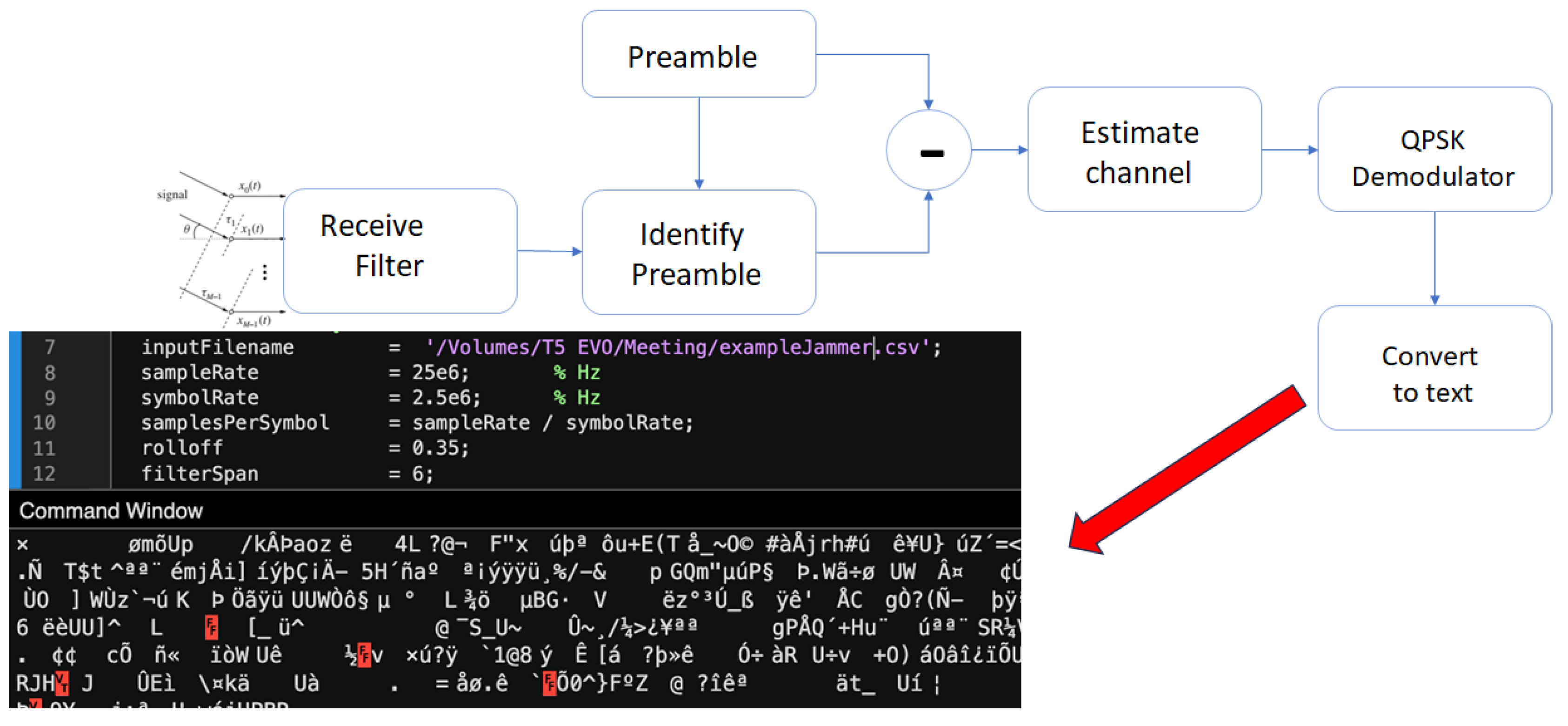
Finally, Figure 27 depicts the decoding pipeline. The IQ samples were passed through a receive filter, preamble detection, and channel estimation, followed by QPSK demodulation and bit-to-text conversion. The original message was successfully recovered with no bit errors. Phase correction was also implicitly performed during the channel estimation stage to ensure coherent demodulation.
4.3.2. Jamming Case: Transmission with Intentional Interference
The second experimental condition replicates the baseline transmission of Section 4.3.1, but with the intentional jammer described in Section 4.1.1 enabled during the entire burst. The objective is to quantify the degradation a co-channel interferer imposes on modulation quality and message recovery. Figure 28 presents the real-time spectrum captured at one receiver. A narrow, high-power spike (left box) originates from the jammer, whereas the broader occupied bandwidth (right box) corresponds to the desired QPSK signal. The interferer elevates the noise floor around the carrier and introduces in-band power that conventional filtering cannot remove. Figure 28 also serves as an illustrative example of the jamming scenario described in the literature, where the jammer occupies the entire bandwidth of interest to disrupt the communication channel.
The constellation and eye analyses in Figure 29 evidence this impairment. Compared with the clean case of Figure 24, symbol clouds are markedly dispersed; Eye diagrams exhibit closing apertures, and modulation metrics (EVM, MER) deteriorate by an order of magnitude. Timing error and frequency offset indicators also increase, reflecting tracking stress under interference.
Figure 30 overlays the ideal transmitted constellation (TX) on the severely scattered received samples (RX). Cluster centroids remain roughly discernible, but symbol decision regions overlap, pushing the Bit-Error-Rate (BER) beyond the threshold for error-free decoding.
Figure 31 contrasts the live (blue) and post-processed (yellow) spectra. Although baseband filtering removes part of the jammer’s narrow tone, residual energy elevates adjacent-channel noise, maintaining constellation distortion.
Finally, the decoding pipeline in Figure 32 illustrates the practical consequence. After receive filtering, preamble detection, and channel estimation, the QPSK demodulator outputs a stream of corrupted bytes: the original sentence is no longer intelligible, confirming that the jammer effectively disrupts message recovery.
Relative to the clean scenario, the jammer raises the in-band noise floor, widens EVM by ca. 10×, collapses eye openings, and ultimately prevents successful text reconstruction. These results highlight the vulnerability of unprotected QPSK links to narrowband, co-channel interference in static V2X deployments.
5. Conclusions
This work investigated the impact of jamming attacks on NR-V2X vehicular communication through both simulation and experimental analysis. Two C-ITS scenarios—DNPW and IMA—were modeled and evaluated using the OMNeT++ environment with Simu5G, Veins, and SUMO. The simulation results demonstrated that periodic jamming can significantly degrade communication performance, increasing packet loss and reducing signal quality during safety-critical time windows. These disruptions persisted even after the end of the attack period, highlighting the fragility of V2X links under adversarial interference. Complementing the simulations, a physical-layer experimental setup was constructed using AnaPico signal generators and Anritsu spectrum analyzers to reproduce controlled jamming conditions. The experiments confirmed that intentional RF interference can compromise message decoding and constellation clarity even under static, line-of-sight configurations. Although the simulation and experiment differ in scenario structure and parameters, both support the conclusion that NR-V2X systems require improved resilience to maintain operational safety under real-world interference conditions. A key limitation of the present experimental setup is the absence of mobility and protocol-level integration, which restricts the scope to static, physical-layer behavior. This simplification was intentional to isolate the effects of jamming at the radio interface. Nonetheless, the lack of dynamic vehicular interactions and complete protocol stack limits the generalizability of the findings to realistic traffic scenarios. Future works may focus on extending the experimental framework to incorporate mobility, enabling the evaluation of jamming effects in dynamic V2X scenarios. Additional directions include testing real-time countermeasures such as frequency hopping, directional transmission, or anomaly detection algorithms. Ultimately, this line of research aims to support the development of more secure and fault-tolerant V2X communication protocols for cooperative autonomous systems.
Author Contributions
Conceptualization, A.S.d.S., G.A.S., D.S.S.C.; methodology, K.H.M.G., D.S.S.C.; software, A.S.d.S., L.F.O.d.M., D.S.S.C.; validation, A.S.d.S., L.F.O.d.M., D.S.S.C.; formal analysis, A.S.d.S., L.F.O.d.M., D.S.S.C.; investigation, K.H.M.G., D.S.S.C.; resources, G.A.S., J.P.J.d.C.; data curation, A.S.d.S., L.F.O.d.M., D.S.S.C.; writing—original draft preparation, D.S.S.C.; writing—review and editing, K.H.M.G., D.A.d.S.; visualization, K.H.M.G., D.S.S.C.; supervision, G.A.S., J.P.J.d.C., J.A.R.V., T.F.; project administration, G.A.S., J.P.J.d.C.; funding acquisition, J.P.J.d.C., J.A.R.V., T.F. All authors have read and agreed to the published version of the manuscript.
Funding
This study was financed in part by the University of Brasilia and in part by the project Beyond 5G Virtuelle Umgebung für Cybersicherheitstests von V2X-Systemen (B5GCyberTestV2X).
Acknowledgments
The authors would like to thank the University of Brasília for institutional support, and the B5GCyberTestV2X project team for collaborative insights.
Conflicts of Interest
The authors declare no conflicts of interest.
Abbreviations
The following abbreviations are used in this manuscript:
| 3GPP | 3rd Generation Partnership Project |
| ARES | Anti-jamming Reinforcement System |
| AVs | Autonomous vehicles |
| C-ITS | Cooperative Intelligent Transport System |
| C-V2X | Cellular Vehicle-to-Everything |
| CV | Connected Vehicle |
| DNPW | Do Not Pass Warning |
| DSRC | Dedicated Short-Range Communication |
| DQN | Deep Q-Networks |
| ETA | Estimated Time of Arrival |
| EVM | Error Vector Magnitude |
| FCC | Federal Communications Commission |
| FDD | Frequency Division Duplex |
| GDBNs | Generalized Dynamic Bayesian Networks |
| GNSS | Global Navigation Satellite System |
| GSHA | Graham Scan Hull Algorithm |
| I-SIG | Intelligent Signal |
| IMA | Intersection Movement Assist |
| IMU | Inertial Measurement Unit |
| ITS | Intelligent Transport Systems |
| MAC | Media Access Control |
| M-MJPF | Modified Markov Jump Particle Filter |
| MSF | Multi-Sensor Fusion |
| NR-V2X | New Radio V2X |
| RF | Radio Frequency |
| RSSI | Received Signal Strength Indicator |
| Rx | Receiver |
| SINR | Signal-to-Interference-plus-Noise Ratio |
| SPS | Semi-Persistent Scheduling |
| TDD | Time Division Duplex |
| TDOA | Time Difference of Arrival |
| TraCI | Traffic Control Interface |
| TSC | Traffic Signal Control |
| Tx | Transmitter |
| UE | User Equipment |
| UMa | Urban Macrocellular |
| UMiSC | Urban Microcellular Street Canyon |
| UMiOS | Urban Microcellular Open Square |
| V2I | Vehicle-to-Infrastructure |
| V2N | Vehicle-to-Network |
| V2P | Vehicle-to-Pedestrian |
| V2V | Vehicle-to-Vehicle |
| V2X | Vehicle-to-Everything |
| VSG | Vector Signal Generator |
Appendix A
Appendix A.1
The following list represents types of jamming attacks in telecommunications [35]. Each attack presents distinct characteristics regarding communication impact, energy efficiency, and interference patterns, as shown in Table A1.
- Constant jamming: These are attacks in which jamming devices emit powerful signals continuously, disrupting legitimate transmissions and occupying the channel.
- Reactive jamming: Known as channel-aware attacks, they are triggered by the detection of legitimate transmissions. They are efficient but require strict timing controls to operate.
- Deceptive jamming: Involves sending multiple radio signals to waste network resources, preventing legitimate access to the channel through saturation.
- Random jamming: The jamming device emits interference signals for random periods, saving energy compared to constant jamming attacks.
- Periodic jamming: The jamming device emits interference pulses in a predictable and regular manner. It can be more energy-efficient than random attacks if the duty cycle is efficiently controlled.
- Frequency sweeping jamming: Allows a jammer to quickly switch between multiple channels, targeting networks even with hardware limitations.

Table A1.
Comparison of Jamming Attack Mechanisms [35].
Table A1.
Comparison of Jamming Attack Mechanisms [35].
| Mechanism | Strengths | Weaknesses |
|---|---|---|
| Constant jamming | Highly effective | Energy inefficient |
| Reactive jamming | Highly effective | Hardware limitations |
| Deceptive jamming | Energy efficient | Less effective |
| Random jamming | Energy efficient | Less effective |
| Periodic jamming | Energy efficient | Less effective |
| Frequency sweeping jamming | Highly effective | Energy inefficient |
References
- Kato, S.; Takeuchi, E.; Ishiguro, Y.; Ninomiya, Y.; Takeda, K.; Hamada, T. An Open Approach to Autonomous Vehicles. IEEE Micro 2015, 35, 60–68. [Google Scholar] [CrossRef]
- Othman, K. Public acceptance and perception of autonomous vehicles: a comprehensive review. AI and Ethics 2021, 1, 355–387. [Google Scholar] [CrossRef] [PubMed]
- Alzalam, I.; Lipps, C.; Schotten, H.D. Time-Series Forecasting Models for 5G Mobile Networks: A Comparative Study in a Cloud Implementation. In Proceedings of the 2024 15th International Conference on Network of the Future (NoF), Castelldefels, Spain, October 2024; pp. 54–62. [Google Scholar] [CrossRef]
- Seredynski, P. Autonomous vehicles and their cloud computing networks, 2021. Accessed on 2025-06-25.
- Tong, W.; Hussain, A.; Bo, W.X.; Maharjan, S. Artificial Intelligence for Vehicle-to-Everything: A Survey. IEEE Access 2019, 7, 10823–10843. [Google Scholar] [CrossRef]
- Munoz, Y.; Dai, W.; Mallikarjun, S.B.; Zentarra, M.; Lipps, C.; Schotten, H.D. Towards Smart Resource Distribution in V2X Dynamic Networks: A Modular RIS Approach. In Proceedings of the Mobilkommunikation; Osnabrück, Germany, May 2024, 28. ITG-Fachtagung; pp. 41–46.
- Hbaieb, A.; Rhaiem, O.B.; Chaari, L. In-car Gateway Architecture for Intra and Inter-vehicular Networks. In Proceedings of the 2018 14th International Wireless Communications &, Limassol, Cyprus, June 2018, Mobile Computing Conference (IWCMC); pp. 1489–1494. [CrossRef]
- Rüb, M.; Grüber, J.; Lipps, C.; Schotten, H.D. Update Rate and Dimension Requirements for Reconfigurable Mirror Arrays in Vehicular Visible Light Communication. In Proceedings of the 2024 IEEE 99th Vehicular Technology Conference (VTC2024-Spring), Singapore, June 2024; pp. 1–6. [Google Scholar] [CrossRef]
- Guan, T.; Han, Y.; Kang, N.; Tang, N.; Chen, X.; Wang, S. An overview of vehicular cybersecurity for intelligent connected vehicles. Sustainability 2022, 14, 5211. [Google Scholar] [CrossRef]
- Nardini, G.; Sabella, D.; Stea, G.; Thakkar, P.; Virdis, A. Simu5G–An OMNeT++ Library for End-to-End Performance Evaluation of 5G Networks. IEEE Access 2020, 8, 181176–181191. [Google Scholar] [CrossRef]
- De Lima, D.V.; Da Silva, A.S.; Da Costa, J.P.J.; Santos, G.A.; Kastell, K.; De Alexandria, A.R.; Da Conceição, M.B. Framework for time-varying DoA estimation and beamforming against radio jamming in V2X applications. In Proceedings of the 2024 24th International Conference on Transparent Optical Networks (ICTON), Bari, Italy, July 2024; pp. 1–4. [Google Scholar] [CrossRef]
- De Lima, D.V.; Da Costa, J.P.J.; Miranda, R.K.; Da Silva, A.A.S.; Santos, G.A.; Vargas, J.A.R.; De Alexandria, A.R. Low Complexity Broadband Array Processing in Dynamic Scenarios with Jamming. In Proceedings of the 2024 IEEE 99th Vehicular Technology Conference (VTC2024-Spring), Singapore, June 2024; pp. 1–6. [Google Scholar] [CrossRef]
- de Lima, D.V.; da Costa, J.P.J.; da Silva, A.A.S.; Santos, G.A.; Vargas, J.A.R.; de Alexandria, A.R. Broadband Beamforming via Frequency Invariance Transformation and PARAFAC Decomposition for Jamming Mitigation in V2X Scenarios. In Proceedings of the 2024 IEEE 99th Vehicular Technology Conference (VTC2024-Spring), Singapore, June 2024; pp. 1–6. [Google Scholar] [CrossRef]
- Müller, C.; Da Costa, J.P.J.; Dos Santos, G.A.; Munoz, Y.; Nozarian, F.; Vozniak, I.; Da Silva, A.S.; Heßler, A. Technical Report on Driving Use Cases for Highly Automated Driving and Key Performance Indicators. Technical report, Heßler,"Technical Report on Driving Use Cases for Highly Automated Driving and Key Performance Indicators", 2023.
- Yang, X.; Shi, Y.; Xing, J.; Liu, Z. Autonomous driving under V2X environment: state-of-the-art survey and challenges. Intelligent Transportation Infrastructure 2022, 1, liac020. [Google Scholar] [CrossRef]
- Harounabadi, M.; Soleymani, D.M.; Bhadauria, S.; Leyh, M.; Roth-Mandutz, E. V2X in 3GPP Standardization: NR Sidelink in Release-16 and Beyond. IEEE Communications Standards Magazine 2021, 5, 12–21. [Google Scholar] [CrossRef]
- Jiang, D.; Delgrossi, L. IEEE 802. In 11p: Towards an International Standard for Wireless Access in Vehicular Environments. In Proceedings of the VTC Spring 2008 - IEEE Vehicular Technology Conference, Marina Bay, Singapore, May 2008; pp. 2036–2040. [Google Scholar] [CrossRef]
- Chen, S.; Hu, J.; Shi, Y.; Zhao, L.; Li, W. A Vision of C-V2X: Technologies, Field Testing, and Challenges With Chinese Development. IEEE Internet of Things Journal 2020, 7, 3872–3881. [Google Scholar] [CrossRef]
- Chen, S.; Hu, J.; Shi, Y.; Peng, Y.; Fang, J.; Zhao, R.; Zhao, L. Vehicle-to-Everything (v2x) Services Supported by LTE-Based Systems and 5G. IEEE Communications Standards Magazine 2017, 1, 70–76. [Google Scholar] [CrossRef]
- Da Silva, A.S.; Da Costa, J.P.J.; Santos, G.A.; Miri, Z.; Fauzi, M.I.B.M.; Vinel, A.; de Freitas, E.P.; Kastell, K. Radio Jamming in Vehicle-to-Everything Communication Systems: Threats and Countermeasures. In Proceedings of the 2023 23rd International Conference on Transparent Optical Networks (ICTON), Bucharest, Romania, July 2023; pp. 1–4. [Google Scholar] [CrossRef]
- Herman Muraro Gularte, K.; Alfredo Ruiz Vargas, J.; Paulo Javidi da Costa, J.; Santos da Silva, A.; Almeida Santos, G.; Wang, Y.; Alfons Müller, C.; Lipps, C.; Timóteo de Sousa Júnior, R.; de Britto Vidal Filho, W.; et al. Safeguarding the V2X Pathways: Exploring the Cybersecurity Landscape Through Systematic Review. IEEE Access 2024, 12, 72871–72895. [Google Scholar] [CrossRef]
- Santos, G.A.; da Costa, J.P.J.; da Silva, A.A.S. Towards to Beyond 5G Virtual Environment for Cybersecurity Testing in V2X Systems. In Proceedings of the 2023 Workshop on Communication Networks and Power Systems (WCNPS), Brasília, Brazil, November-December 2023; pp. 1–7. [Google Scholar] [CrossRef]
- Herman Muraro Gularte, K.; Paulo Javidi da Costa, J.; Vargas, J.A.R.; Santos da Silva, A.; Almeida Santos, G.; Wang, Y.; Alfons Müller, C.; Lipps, C.; Timóteo de Sousa, R.; de Britto Vidal Filho, W.; et al. Integrating Cybersecurity in V2X: A Review of Simulation Environments. IEEE Access 2024, 12, 177946–177985. [Google Scholar] [CrossRef]
- Yao, Y.; Zhao, J.; Li, Z.; Cheng, X.; Wu, L. Jamming and Eavesdropping Defense Scheme Based on Deep Reinforcement Learning in Autonomous Vehicle Networks. IEEE Transactions on Information Forensics and Security 2023, 18, 1211–1224. [Google Scholar] [CrossRef]
- Pelechrinis, K.; Broustis, I.; Krishnamurthy, S.V.; Gkantsidis, C. A Measurement-Driven Anti-Jamming System for 802.11 Networks. IEEE/ACM Transactions on Networking 2011, 19, 1208–1222. [Google Scholar] [CrossRef]
- Krayani, A.; William, N.J.; Marcenaro, L.; Regazzoni, C. Jammer Detection in Vehicular V2X Networks. In Proceedings of the 2022 Microwave Mediterranean Symposium (MMS), Pizzo Calabro, Italy, May 2022; pp. 1–5. [Google Scholar] [CrossRef]
- Alam, M.S.; Oluoch, J.; Kim, J. A Mechanism to Localize, Detect, and Prevent Jamming in Connected and Autonomous Vehicles (CAVs). IEEE Transactions on Intelligent Transportation Systems 2023, 25, 1215–1224. [Google Scholar] [CrossRef]
- Twardokus, G.; Rahbari, H. Toward Protecting 5G Sidelink Scheduling in C-V2X Against Intelligent DoS Attacks. IEEE Transactions on Wireless Communications 2023, 22, 7273–7286. [Google Scholar] [CrossRef]
- Yang, M.; Ju, Y.; Liu, L.; Pei, Q.; Yu, K.; Rodrigues, J.J.P.C. Secure mmWave C-V2X Communications Using Cooperative Jamming. In Proceedings of the GLOBECOM 2022 - 2022 IEEE Global Communications Conference, Rio de Janeiro, Brazil, December 2022; pp. 2686–2691. [Google Scholar] [CrossRef]
- Wyglinski, A.M.; Wickramarathne, T.; Chen, D.; Kirsch, N.J.; Gill, K.S.; Jain, T.; Garg, V.; Li, T.; Paul, S.; Xi, Z. Phantom Car Attack Detection via Passive Opportunistic RF Localization. IEEE Access 2023, 11, 27676–27692. [Google Scholar] [CrossRef]
- Feng, Y.; Huang, S.E.; Wong, W.; Chen, Q.A.; Mao, Z.M.; Liu, H.X. On the Cybersecurity of Traffic Signal Control System With Connected Vehicles. IEEE Transactions on Intelligent Transportation Systems 2022, 23, 16267–16279. [Google Scholar] [CrossRef]
- Shen, J.; Wan, Z.; Luo, Y.; Feng, Y.; Mao, Z.M.; Chen, Q.A. Detecting Data Spoofing in Connected Vehicle based Intelligent Traffic Signal Control using Infrastructure-Side Sensors and Traffic Invariants. In Proceedings of the 2023 IEEE Intelligent Vehicles Symposium (IV), Anchorage, AK, USA, June 2023; pp. 1–8. [Google Scholar] [CrossRef]
- Yang, Z.; Ying, J.; Shen, J.; Feng, Y.; Chen, Q.A.; Mao, Z.M.; Liu, H.X. Anomaly Detection Against GPS Spoofing Attacks on Connected and Autonomous Vehicles Using Learning From Demonstration. IEEE Transactions on Intelligent Transportation Systems 2023, 24, 9462–9475. [Google Scholar] [CrossRef]
- Pusapati, S.; Selim, B.; Nie, Y.; Lin, H.; Peng, W. Simulation of NR-V2X in a 5G Environment using OMNeT++. In Proceedings of the 2022 IEEE Future Networks World Forum (FNWF), Montreal, QC, Canada, October 2022; pp. 634–638. [Google Scholar] [CrossRef]
- Pirayesh, H.; Zeng, H. Jamming Attacks and Anti-Jamming Strategies in Wireless Networks: A Comprehensive Survey. IEEE Communications Surveys & Tutorials 2022, 24, 767–809. [Google Scholar] [CrossRef]
Figure 1.
DNPW Visual Representation.
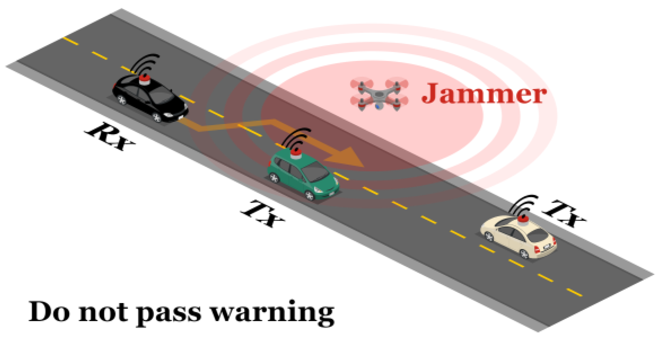
Figure 2.
IMA Visual Representation.
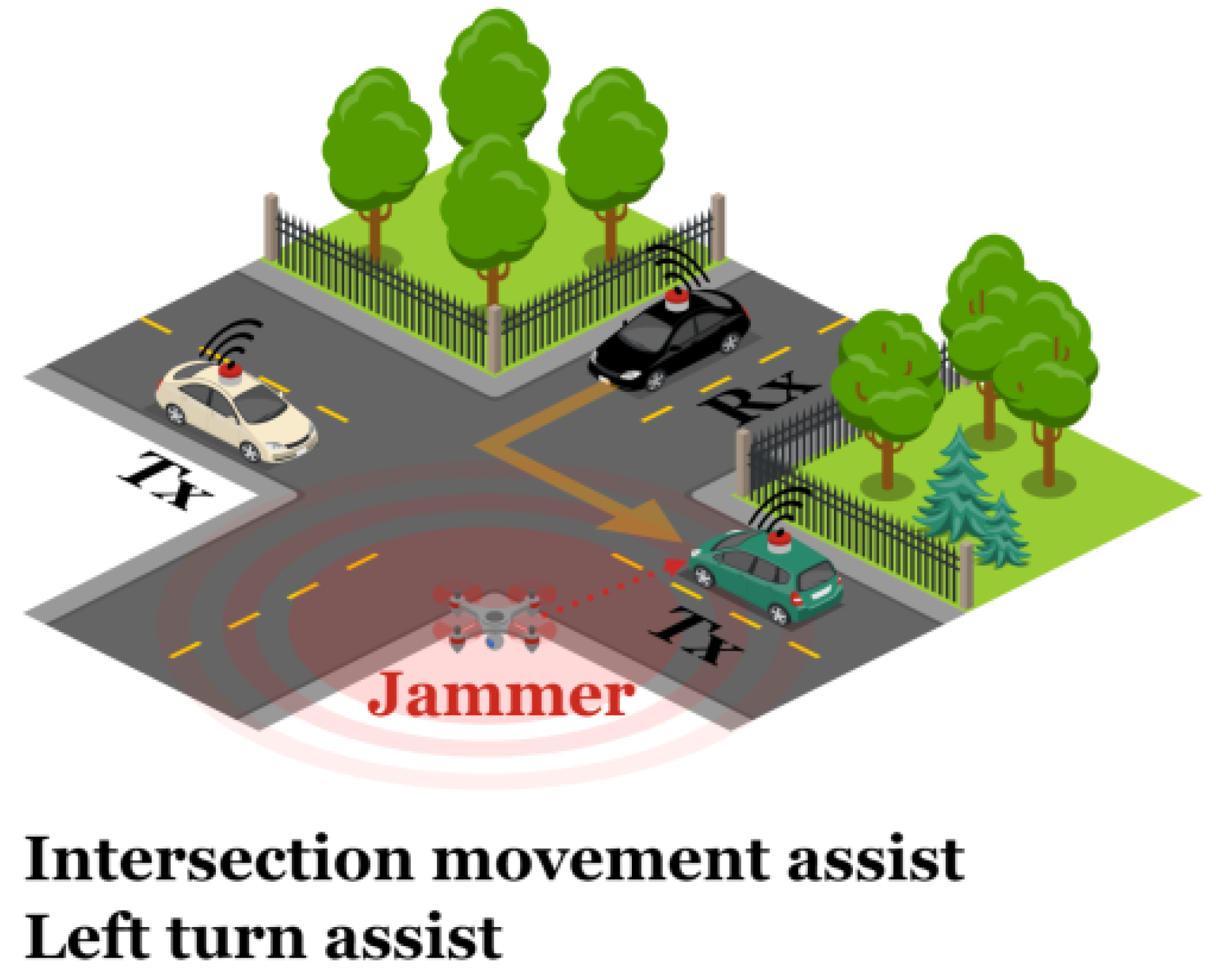
Figure 3.
Modular Architecture of Simulation Tools. Source: adapted from [25].
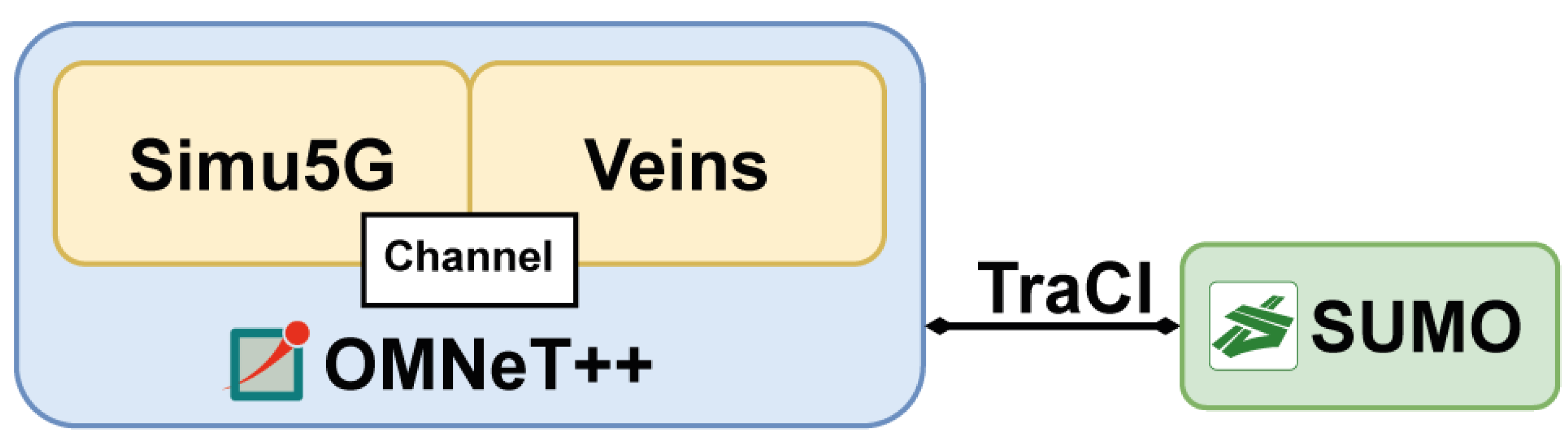
Figure 4.
UML Diagram of the OMNeT++ NED implementation.
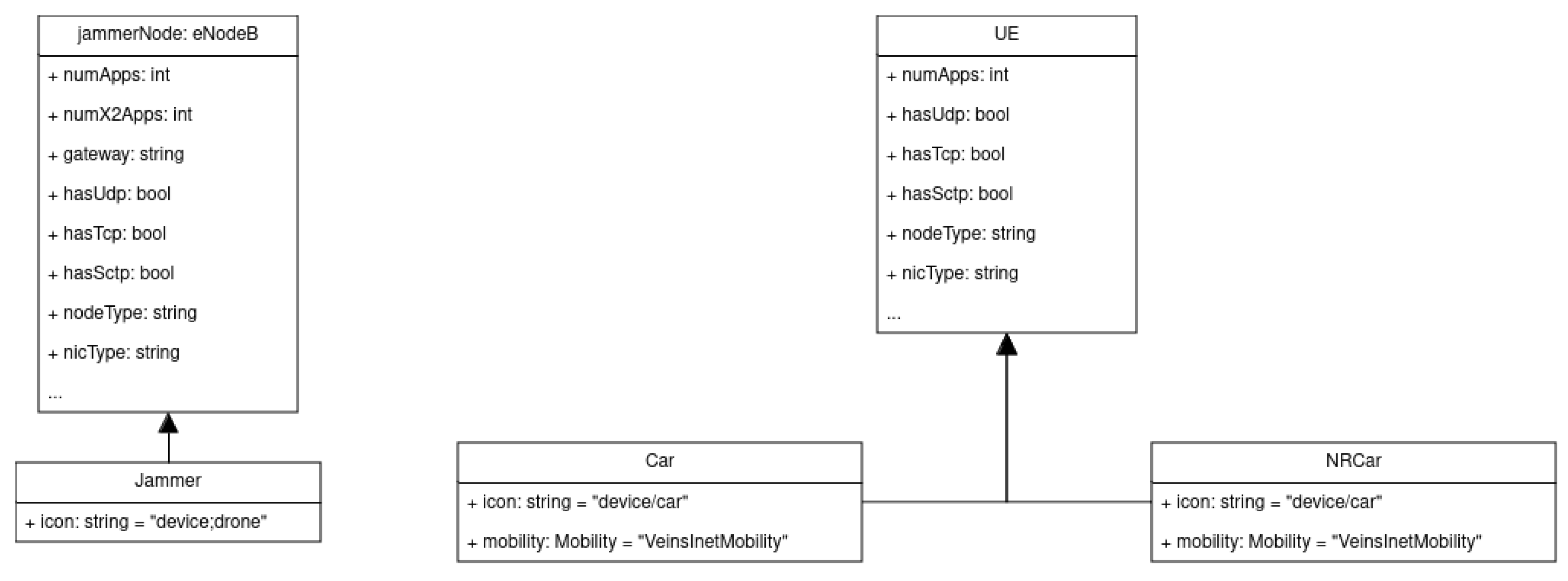
Figure 5.
Execution of the attack in the DNPW scenario.
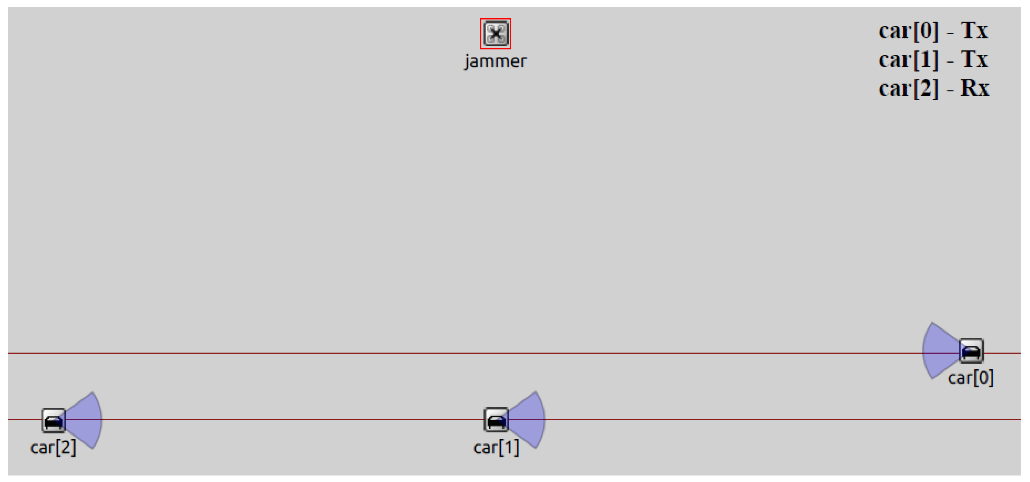
Figure 6.
Parameters in the DNPW Scenario between the transmitter car[0] and the receiver car[2].
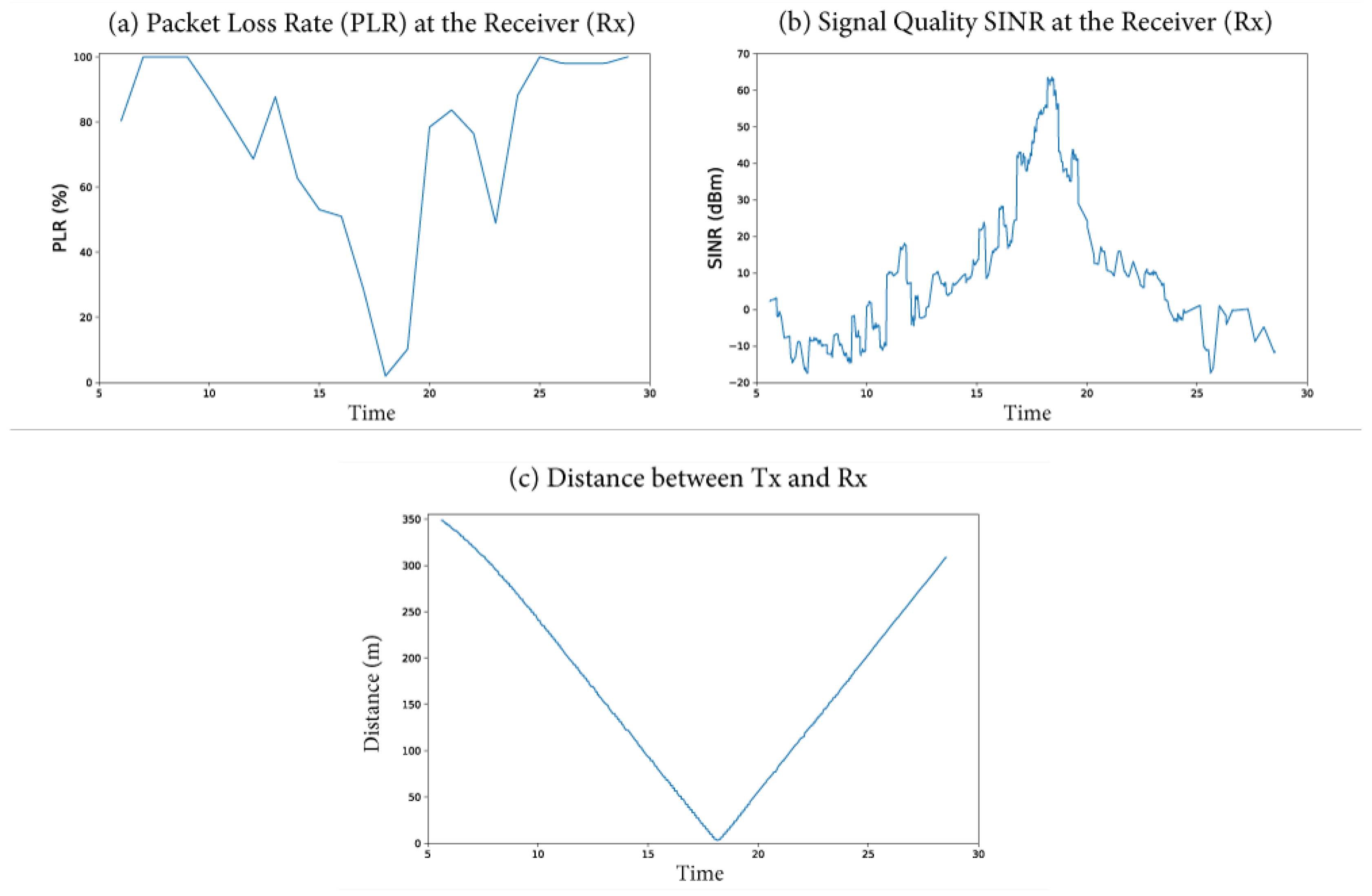
Figure 7.
Parameters in the DNPW Scenario between the transmitter car[1] and the receiver car[2].
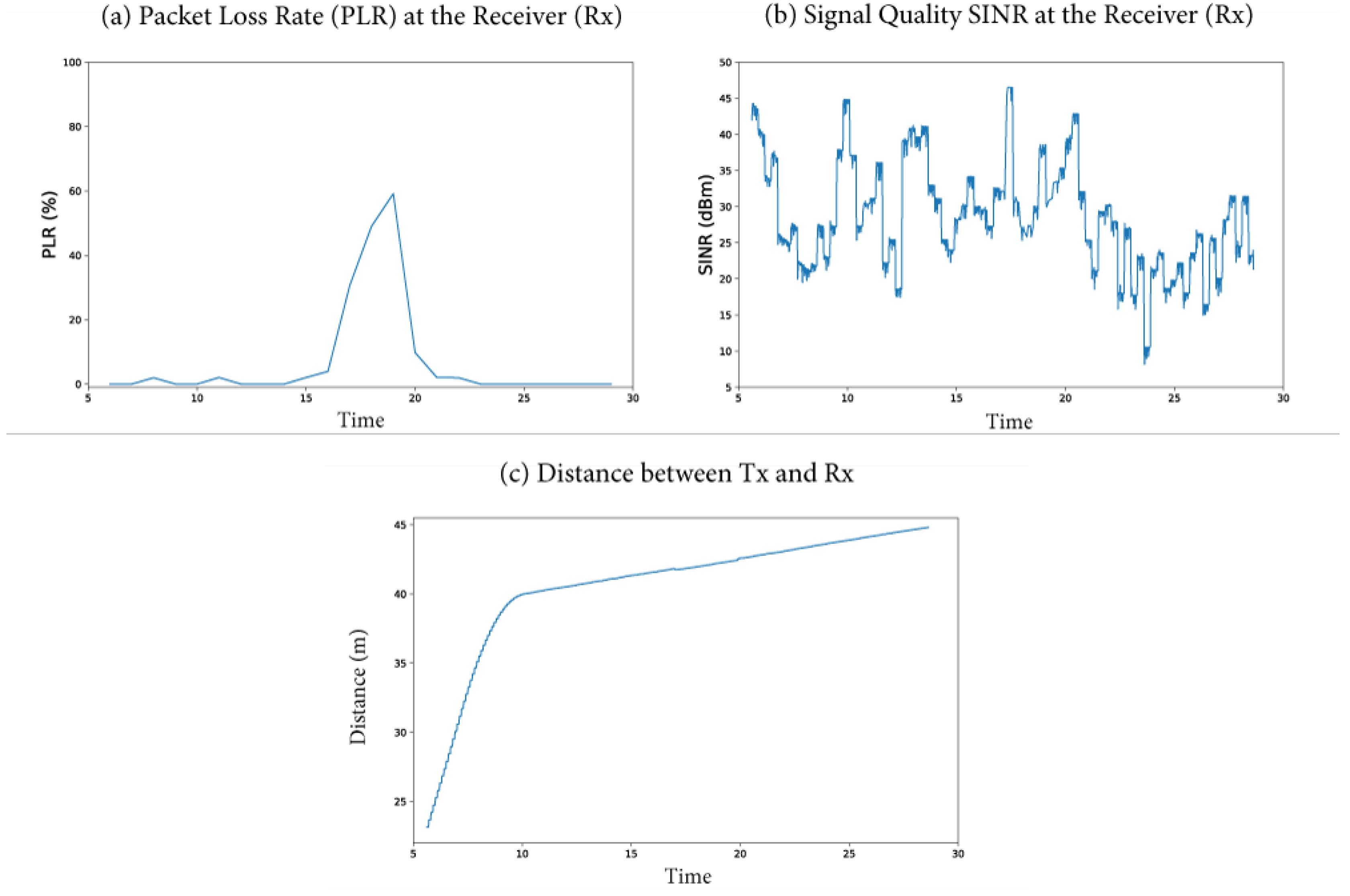
Figure 8.
Variation in the packet loss rate between car[0] and car[2] in the DNPW.
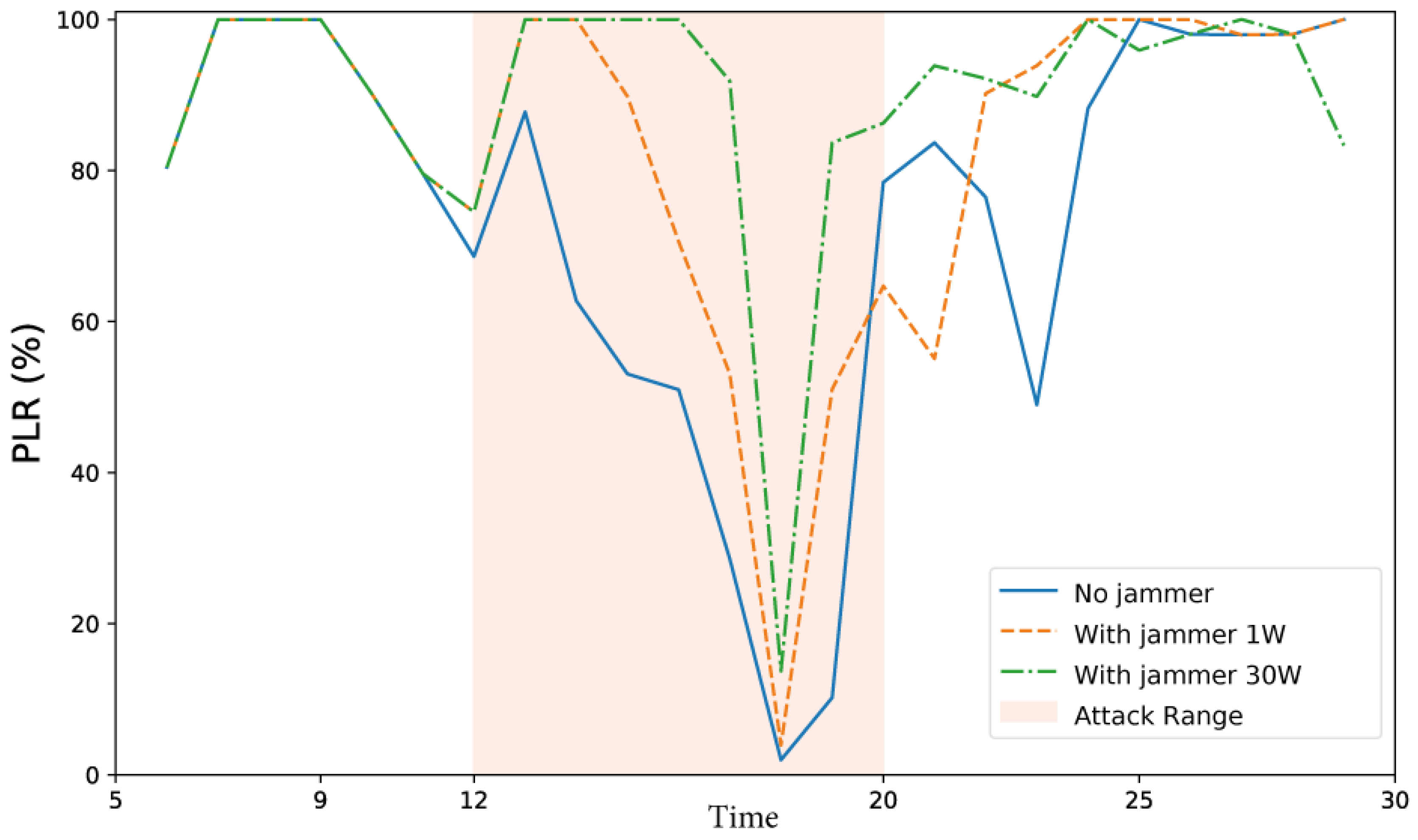
Figure 9.
Variation of signal quality between car[0] and car[2] in the DNPW.
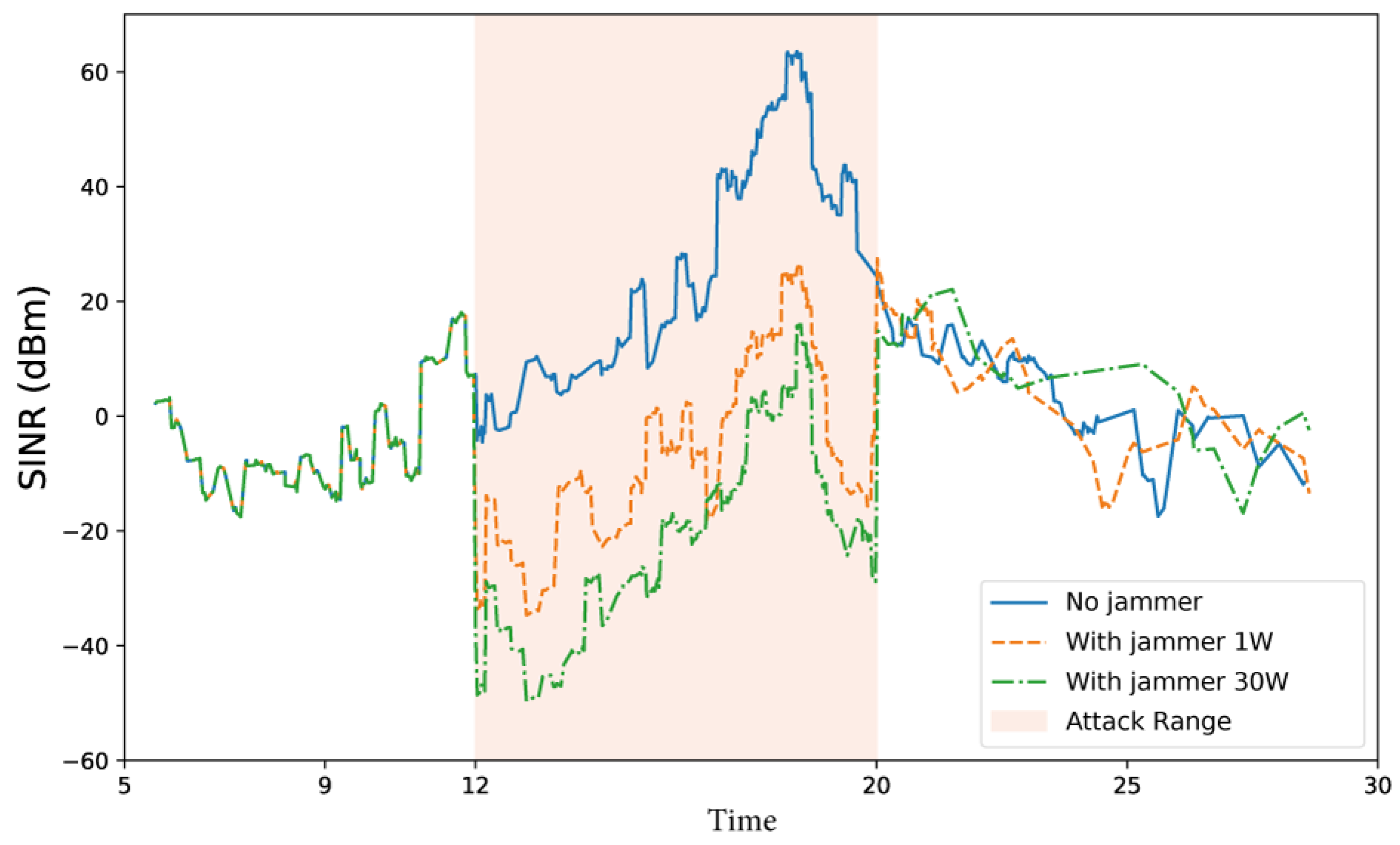
Figure 10.
Variation of packet loss rate between car[1] and car[2] in the DNPW.
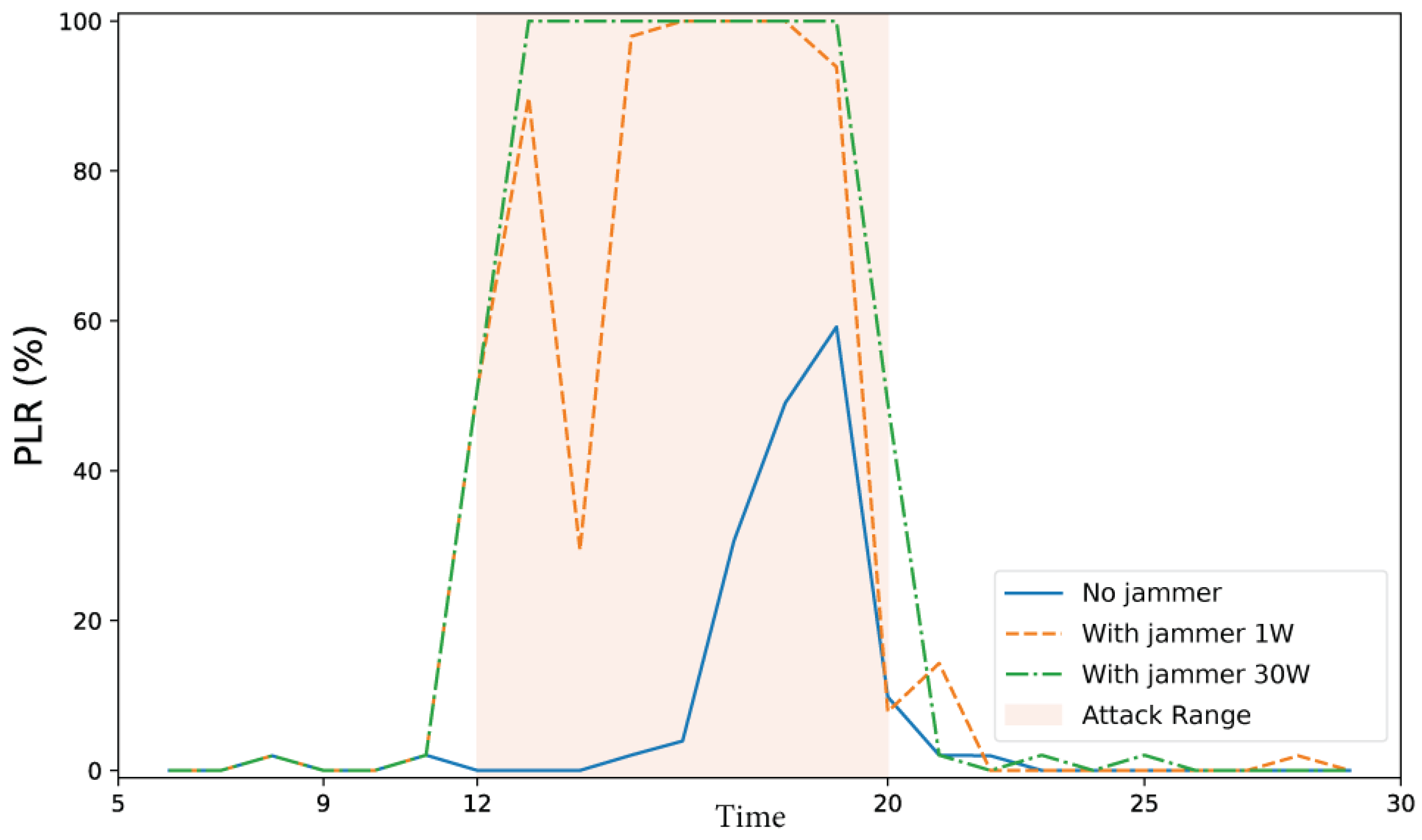
Figure 11.
Variation in signal quality between car[1] and car[2] in the DNPW.
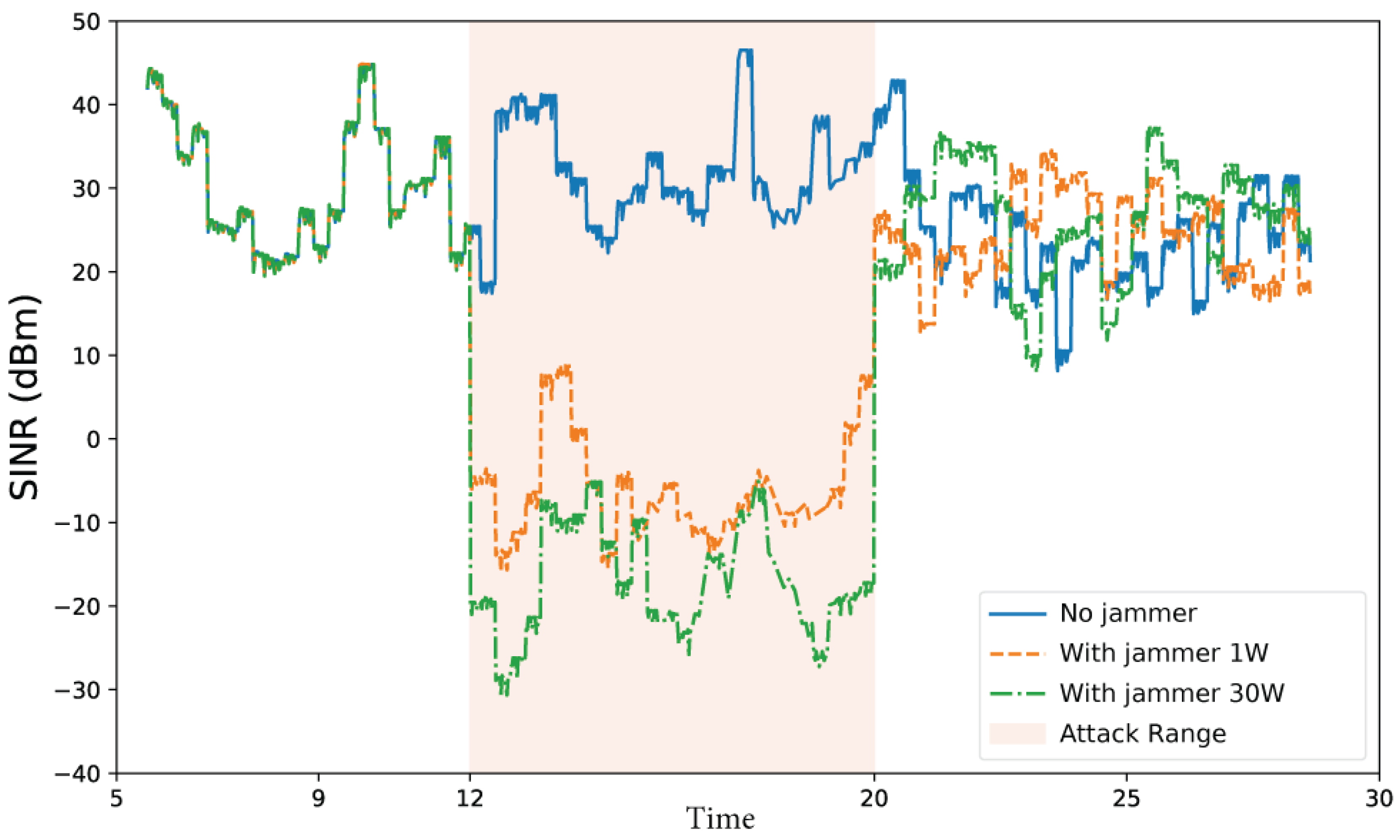
Figure 12.
Execution of the attack in the IMA scenario.
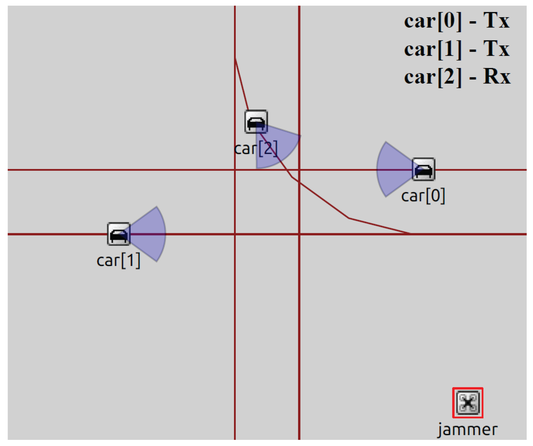
Figure 13.
Parameters in the IMA Scenario between the transmitter car[0] and the receiver car[2].
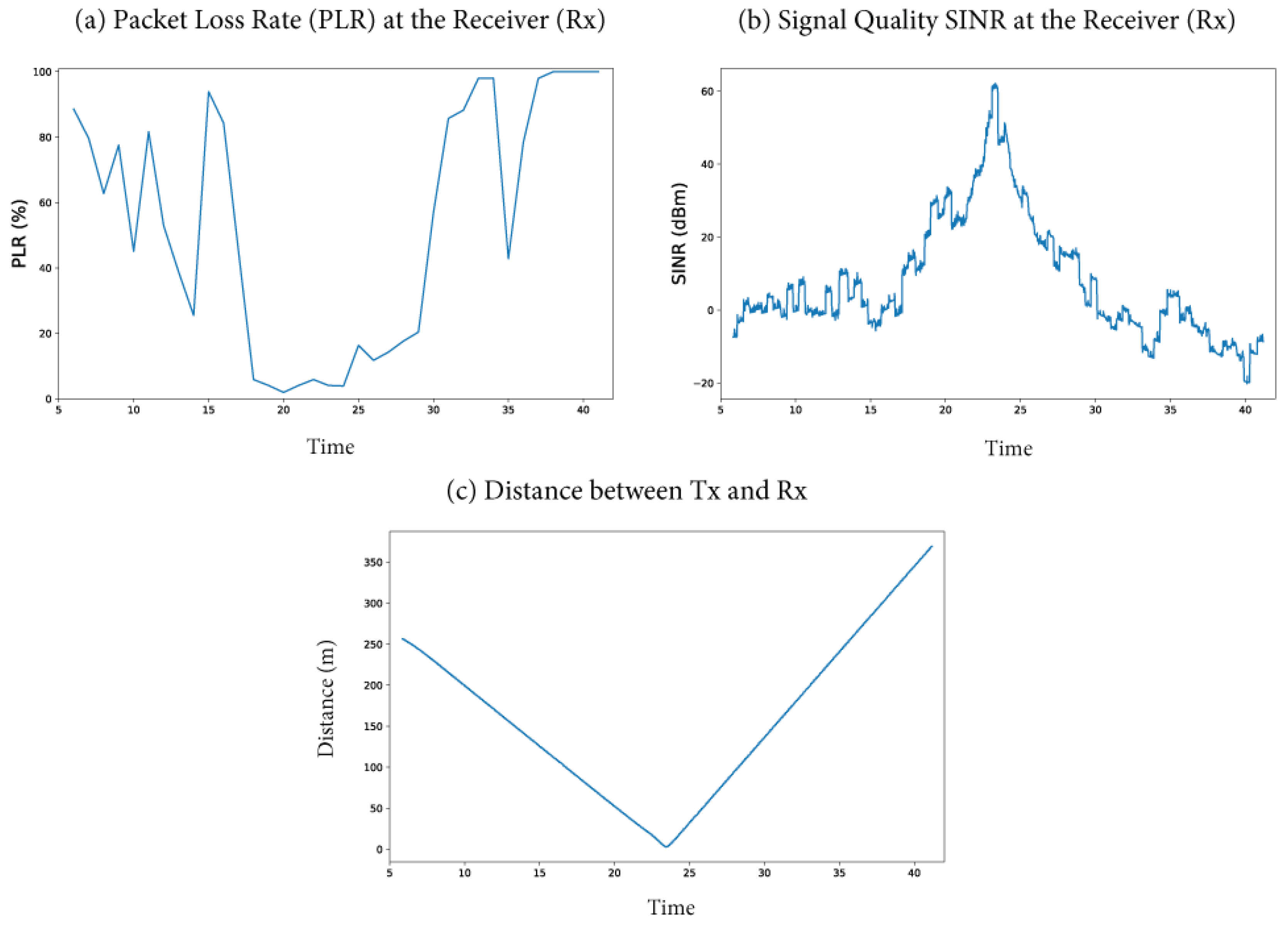
Figure 14.
Parameters in the IMA Scenario between the transmitter car[1] and the receiver car[2].
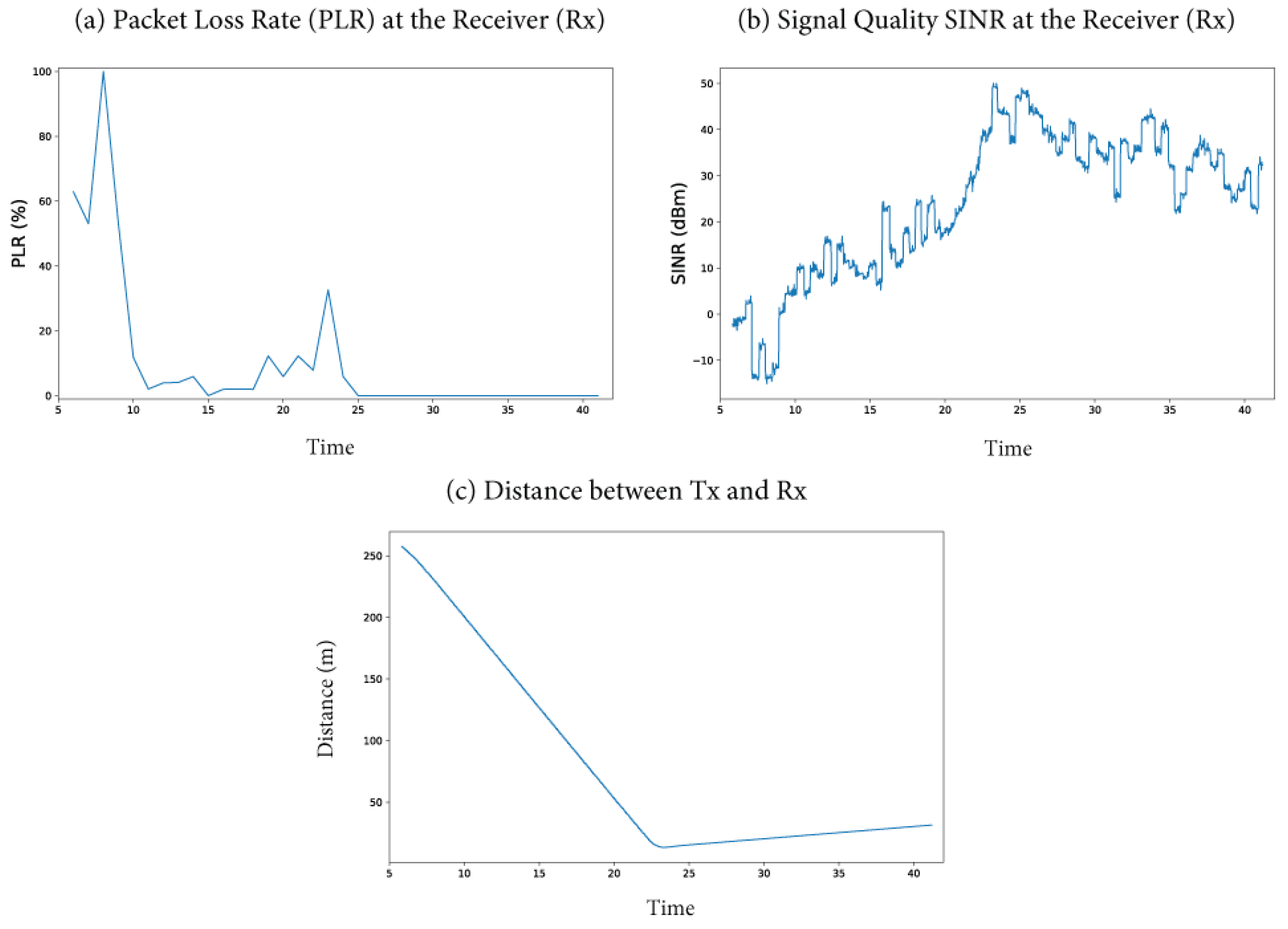
Figure 15.
Variation of packet loss rate between car[0] and car[2] in the IMA.
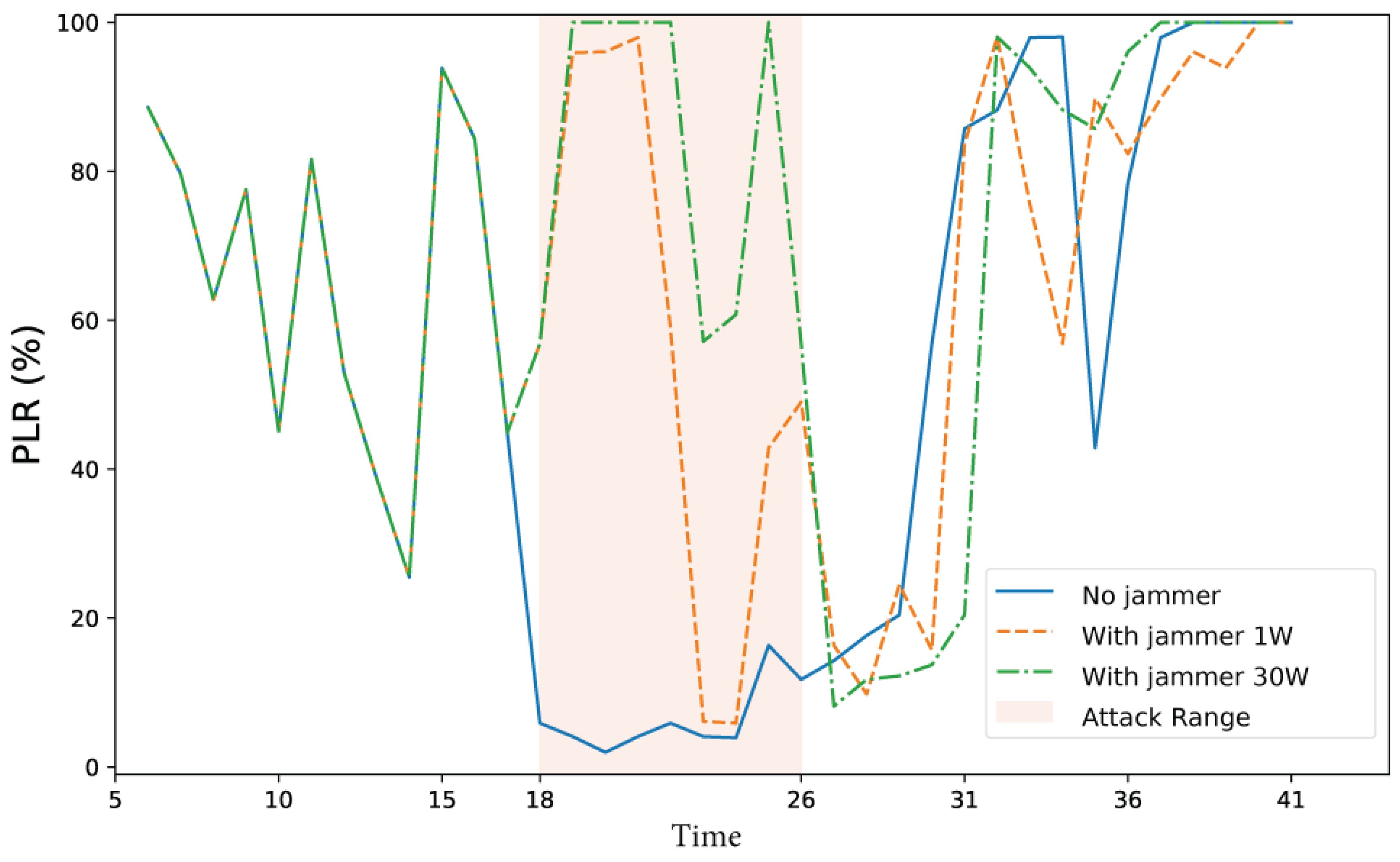
Figure 16.
Variation in signal quality between car[0] and car[2] in the IMA.
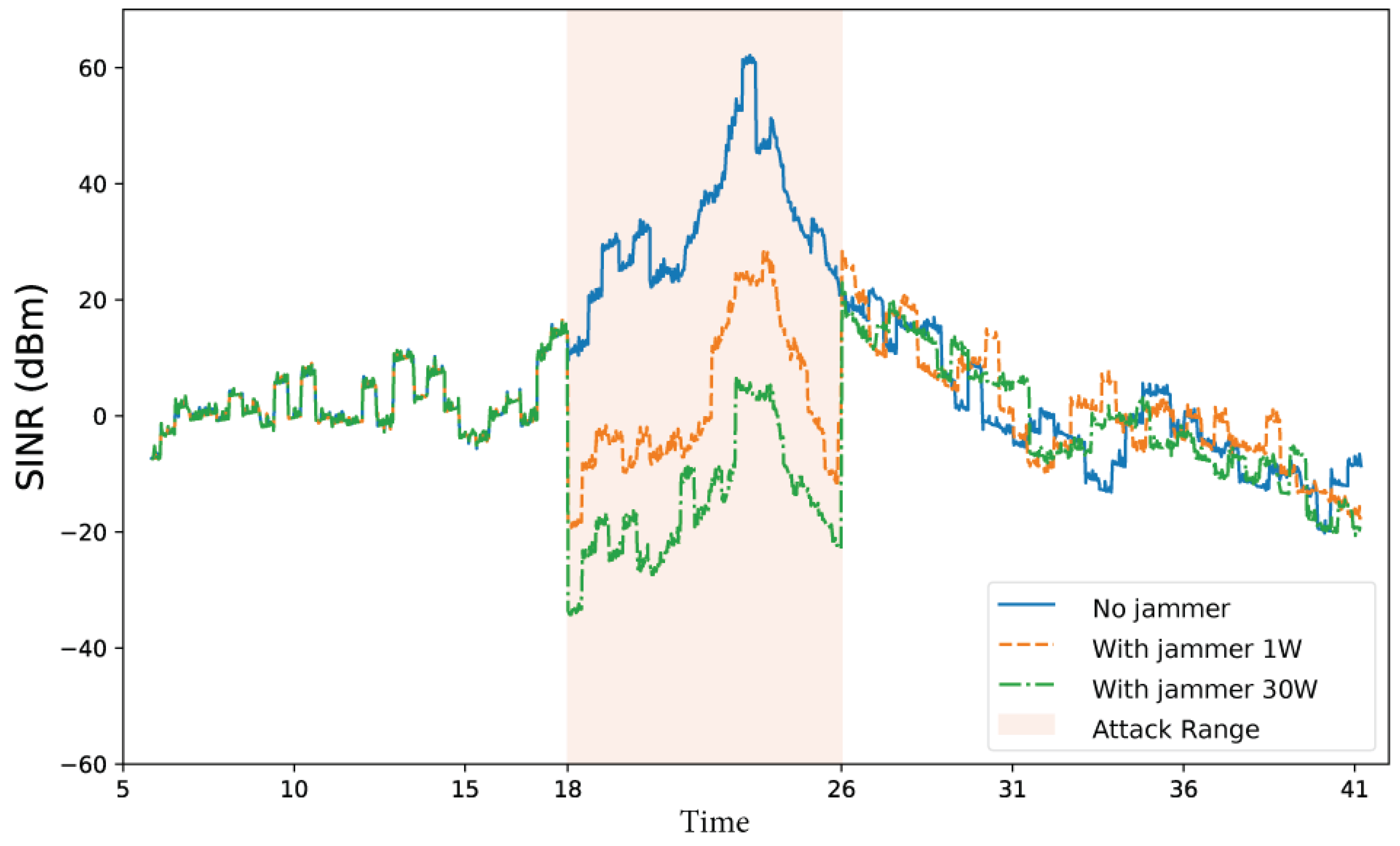
Figure 17.
Variation in packet loss rate between car[1] and car[2] in the IMA.
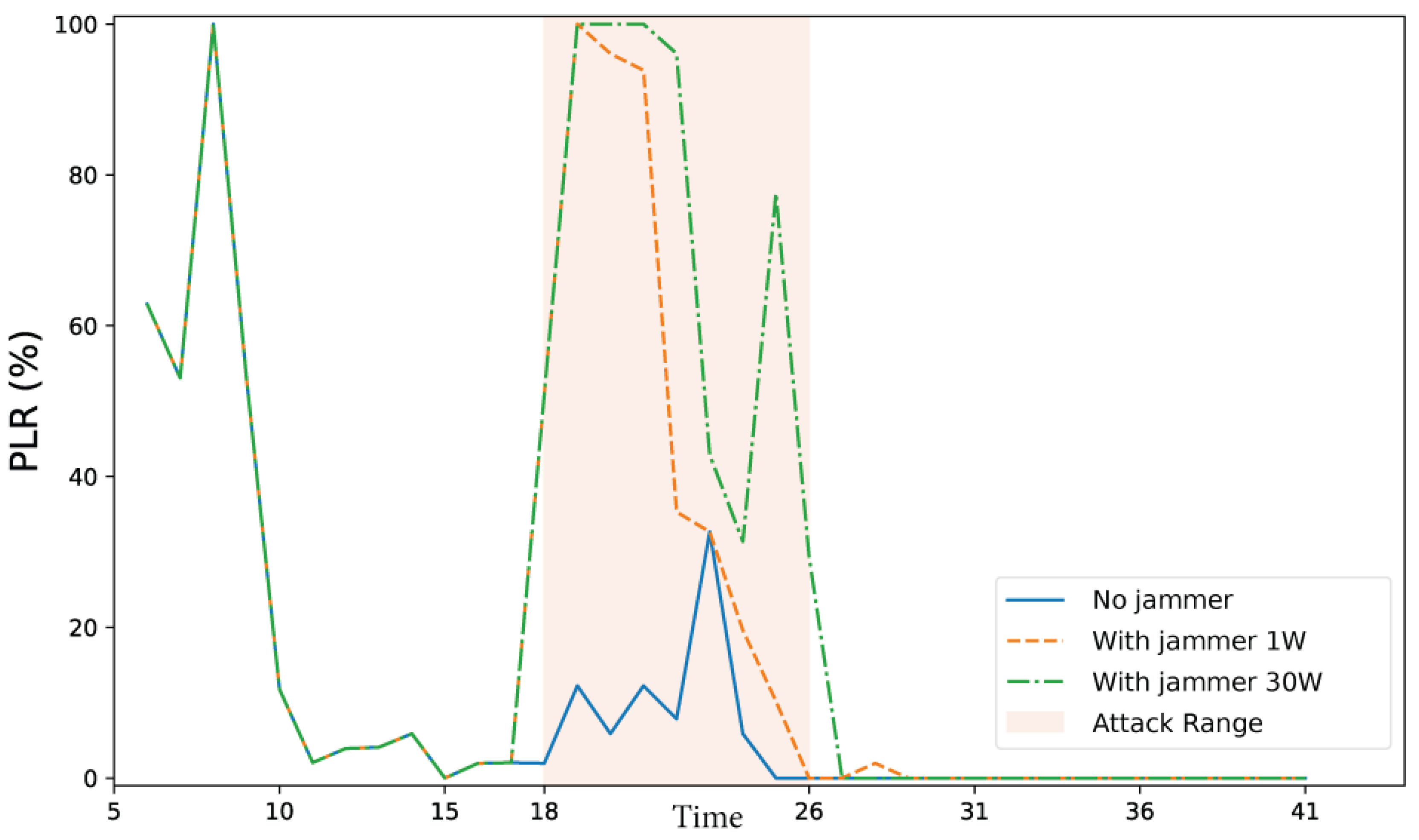
Figure 18.
Variation in signal quality between car[1] and car[2] in the IMA.
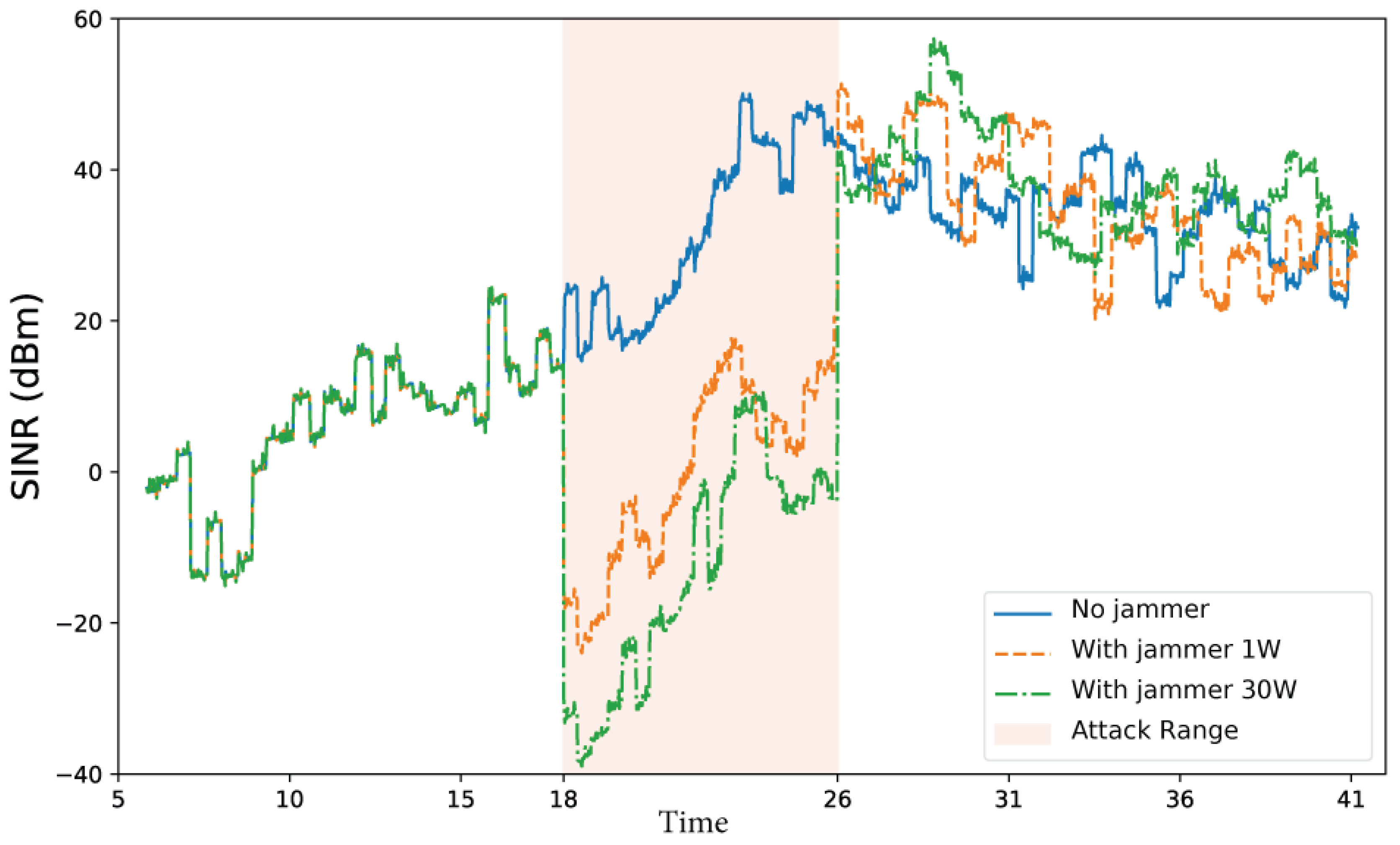
Figure 19.
Close-up of the AnaPico APVSG40 stack. The red unit (top) acts as a jammer. The black unit below provides four phase-coherent data channels.
Figure 19.
Close-up of the AnaPico APVSG40 stack. The red unit (top) acts as a jammer. The black unit below provides four phase-coherent data channels.
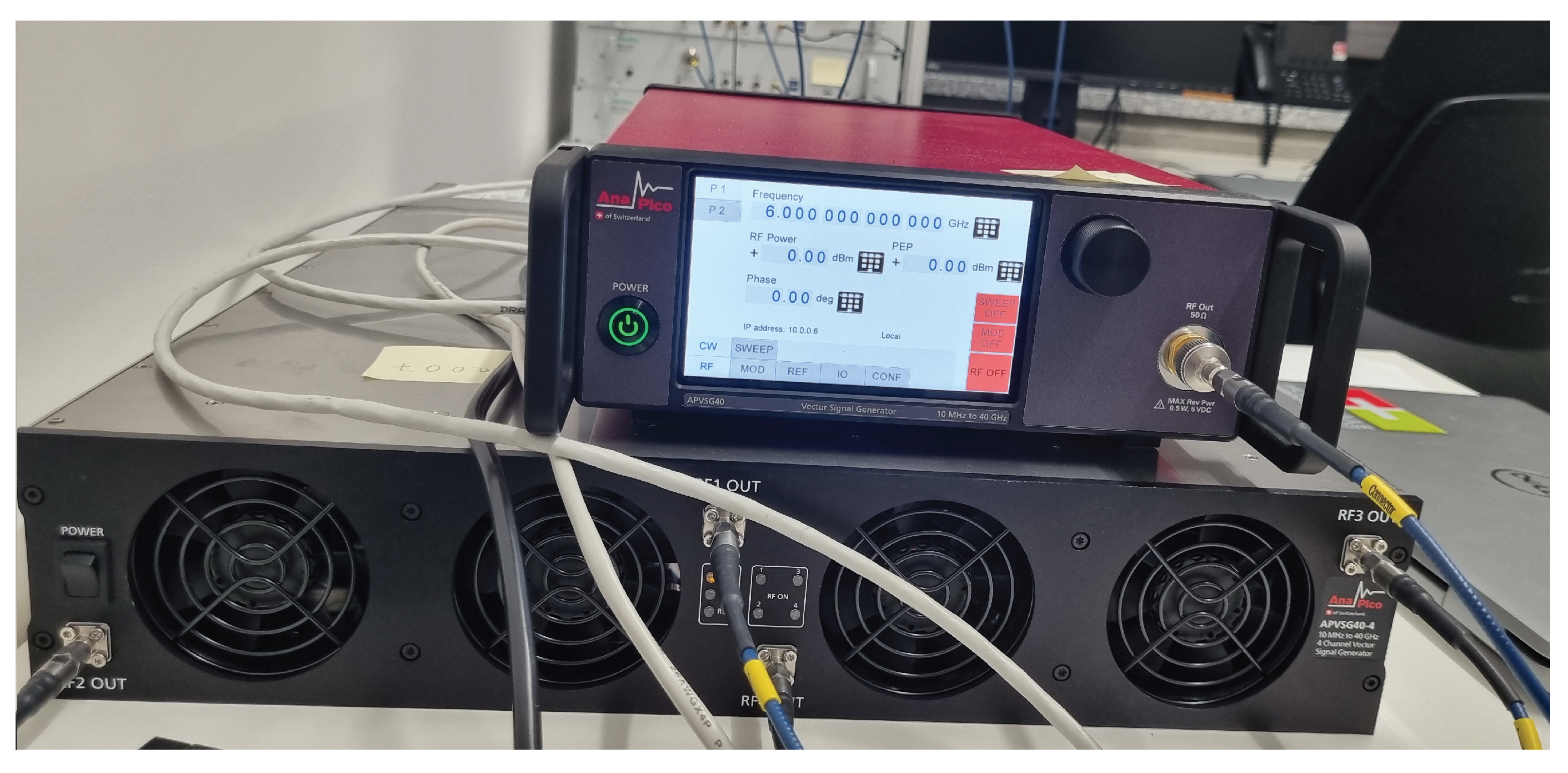
Figure 20.
Full system layout, including the jammer antenna (far right). The interfering signal originates from the red AnaPico unit and is emitted from a spatially offset horn to disrupt reception. Four ERAVANT horn antennas on the left transmit encoded signals from the AnaPico stack. Four central antennas receive and forward decoded signals from the MS27201A spectrum monitors. One antenna on the right transmits signals from the second APVSG40 generator.
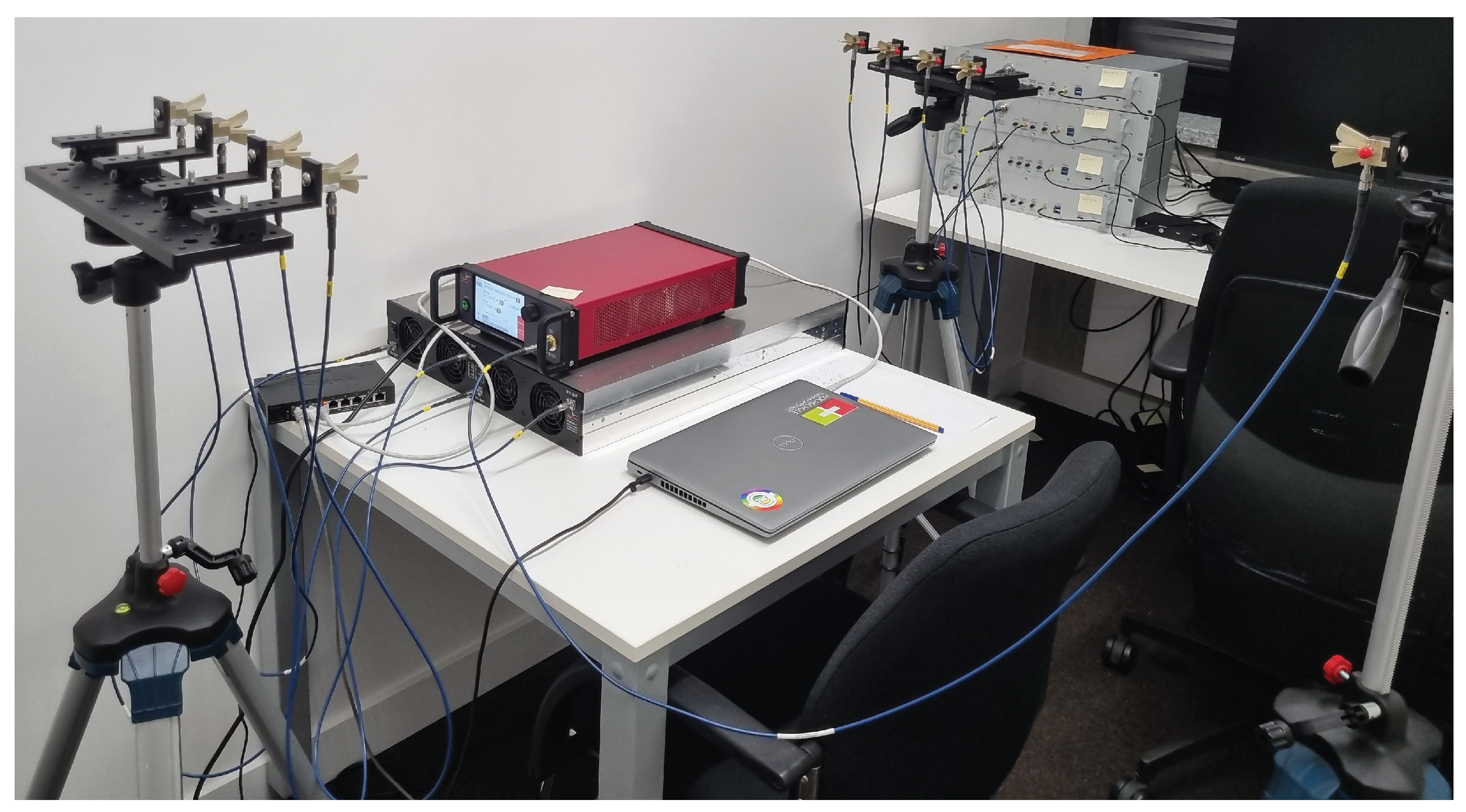
Figure 21.
Block diagram of the NR-V2X jamming experiment setup. Desired (red) and jamming (blue) signals propagate from the AnaPico APVSG40-4 and the dedicated jammer, respectively, toward a four-element receiver array connected to the Anritsu MS27201A. Triangular shapes represent antennas in the system.
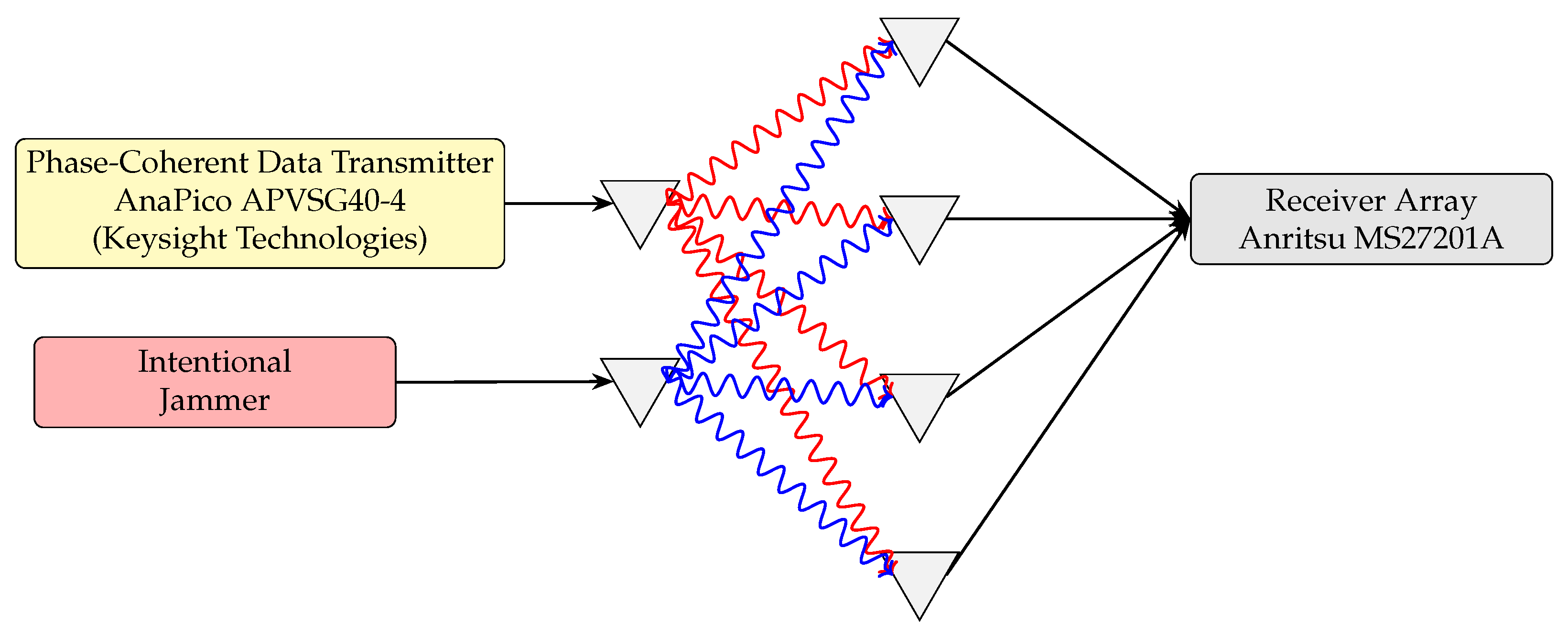
Figure 22.
Close-up of the decoding hardware: stack of four Anritsu MS27201A spectrum monitors, each assigned to one RF reception path.
Figure 22.
Close-up of the decoding hardware: stack of four Anritsu MS27201A spectrum monitors, each assigned to one RF reception path.
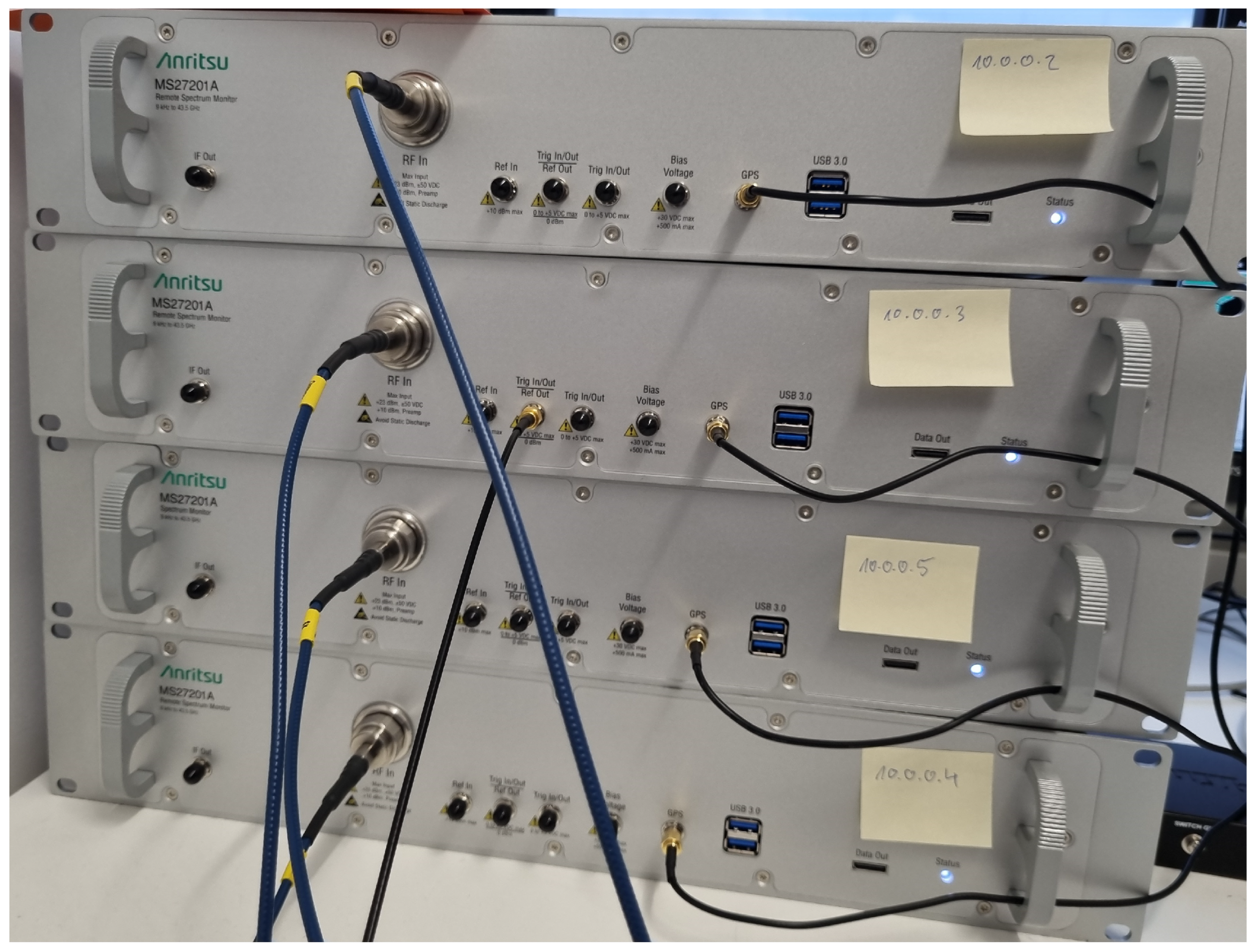
Figure 23.
Transmission pipeline: message encoding, QPSK modulation, preamble insertion, filtering, and IQ file generation.
Figure 23.
Transmission pipeline: message encoding, QPSK modulation, preamble insertion, filtering, and IQ file generation.
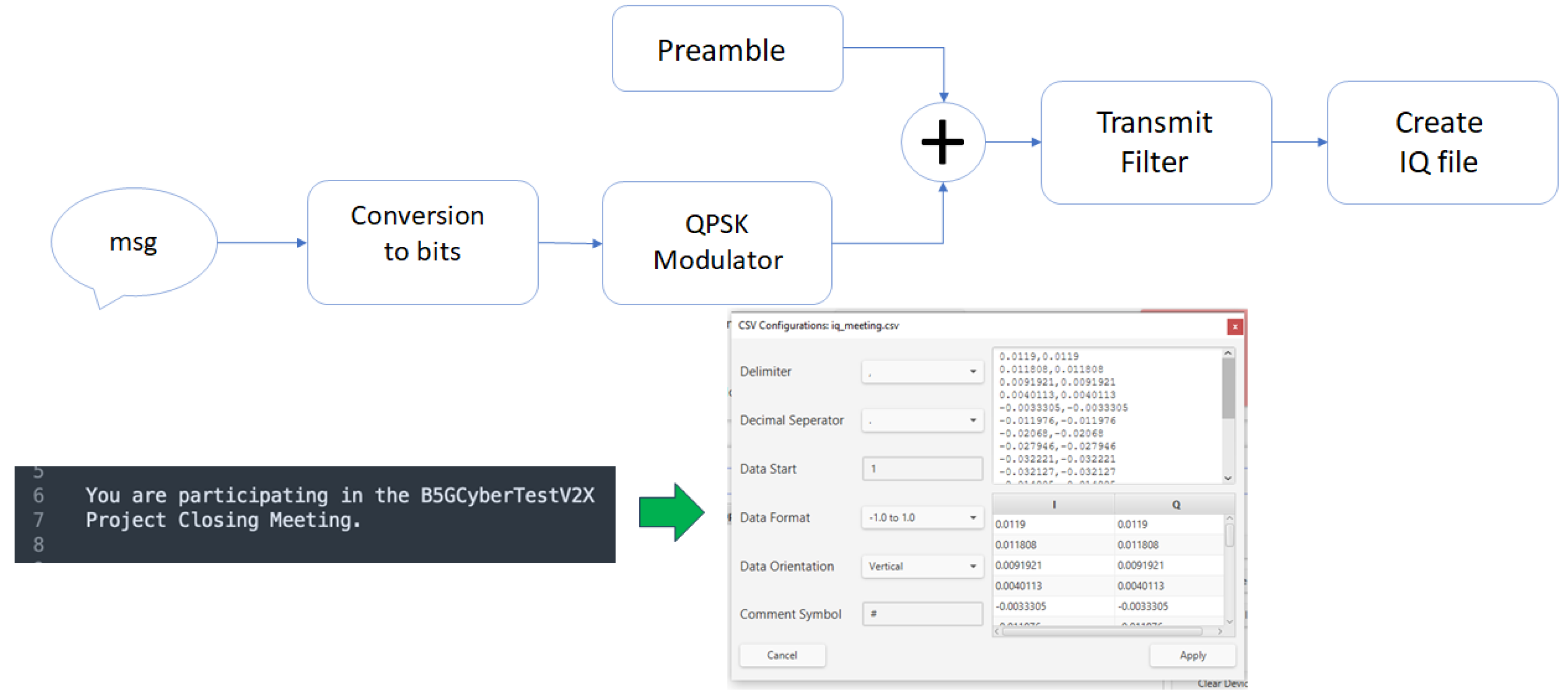
Figure 24.
Constellation, eye diagram, and spectral view of the received signal under clean transmission.
Figure 24.
Constellation, eye diagram, and spectral view of the received signal under clean transmission.
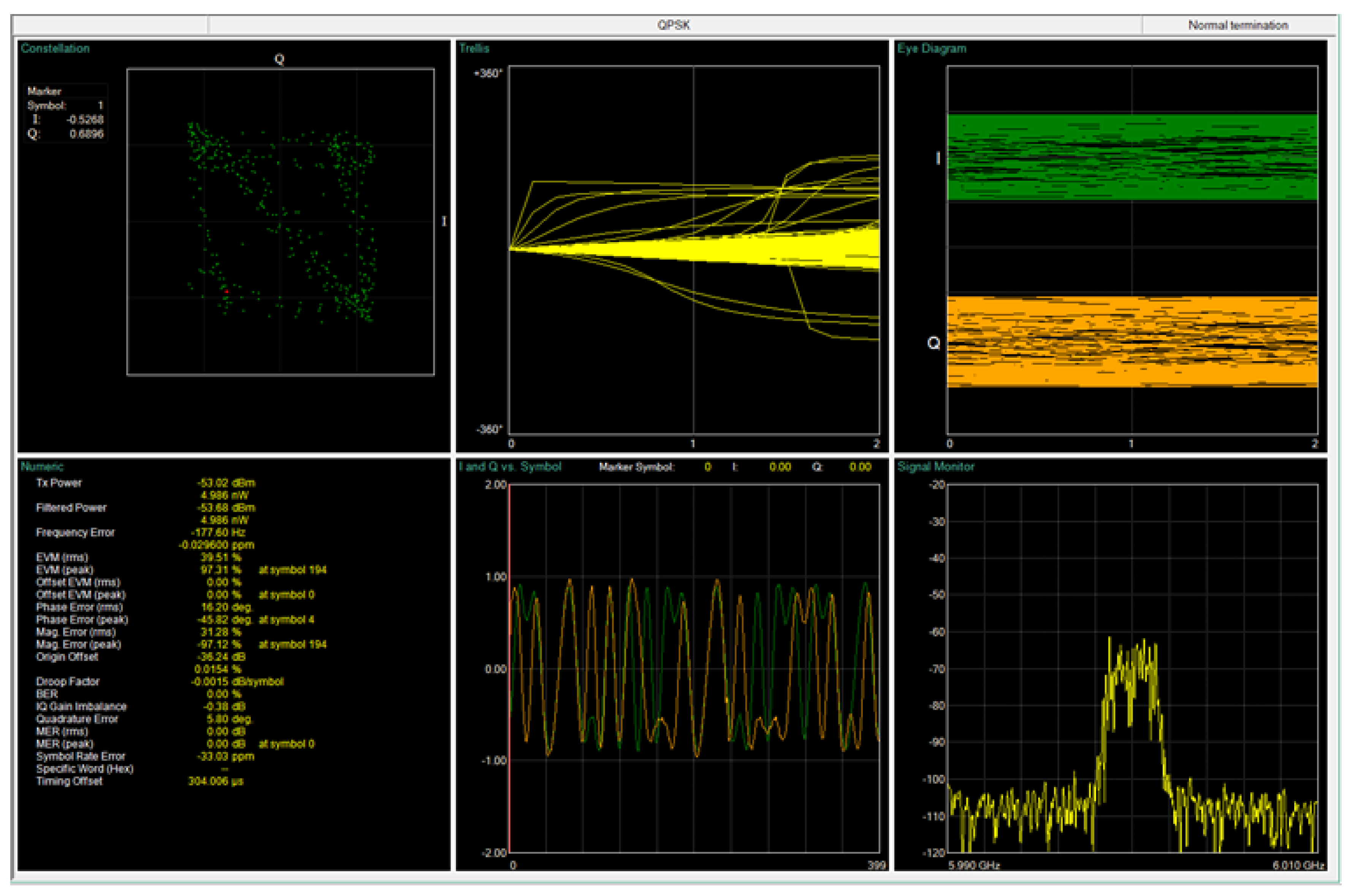
Figure 25.
Comparison between transmitter (TX) and received (RX) constellations for the baseline case.
Figure 25.
Comparison between transmitter (TX) and received (RX) constellations for the baseline case.
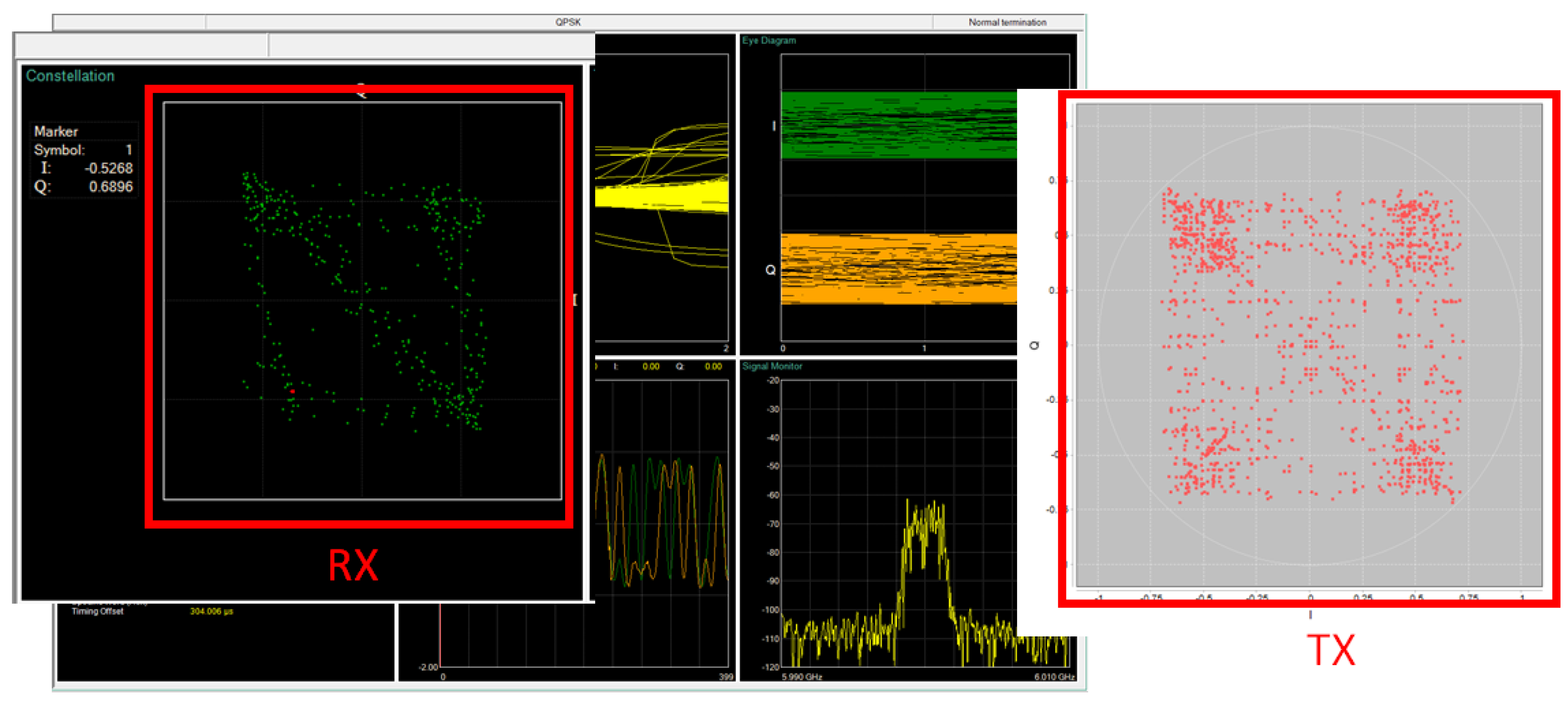
Figure 26.
Live RF spectrum (blue) and filtered post-processed signal (yellow) from one receiver.
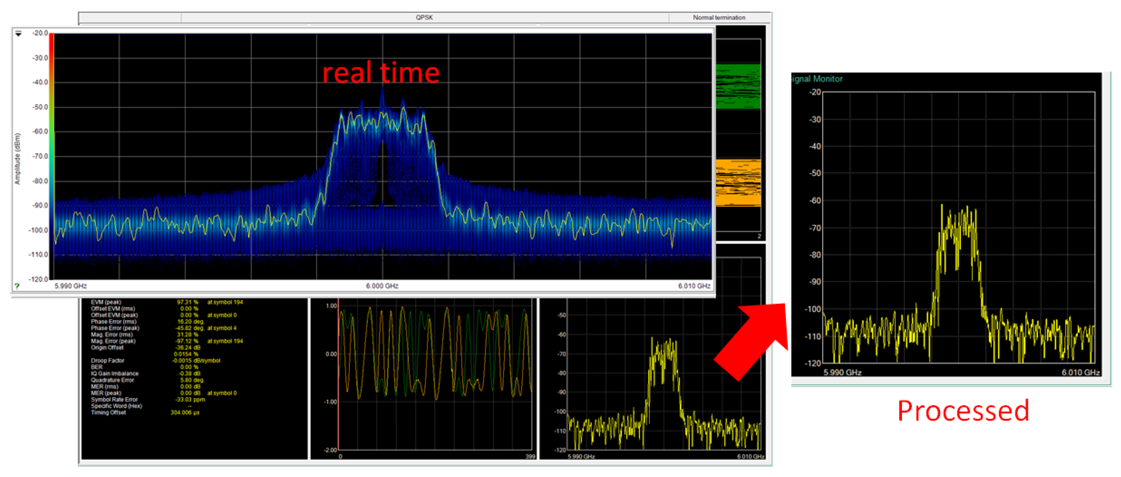
Figure 27.
Reception and decoding pipeline: receive filtering, preamble detection, channel estimation, demodulation, and message reconstruction.
Figure 27.
Reception and decoding pipeline: receive filtering, preamble detection, channel estimation, demodulation, and message reconstruction.
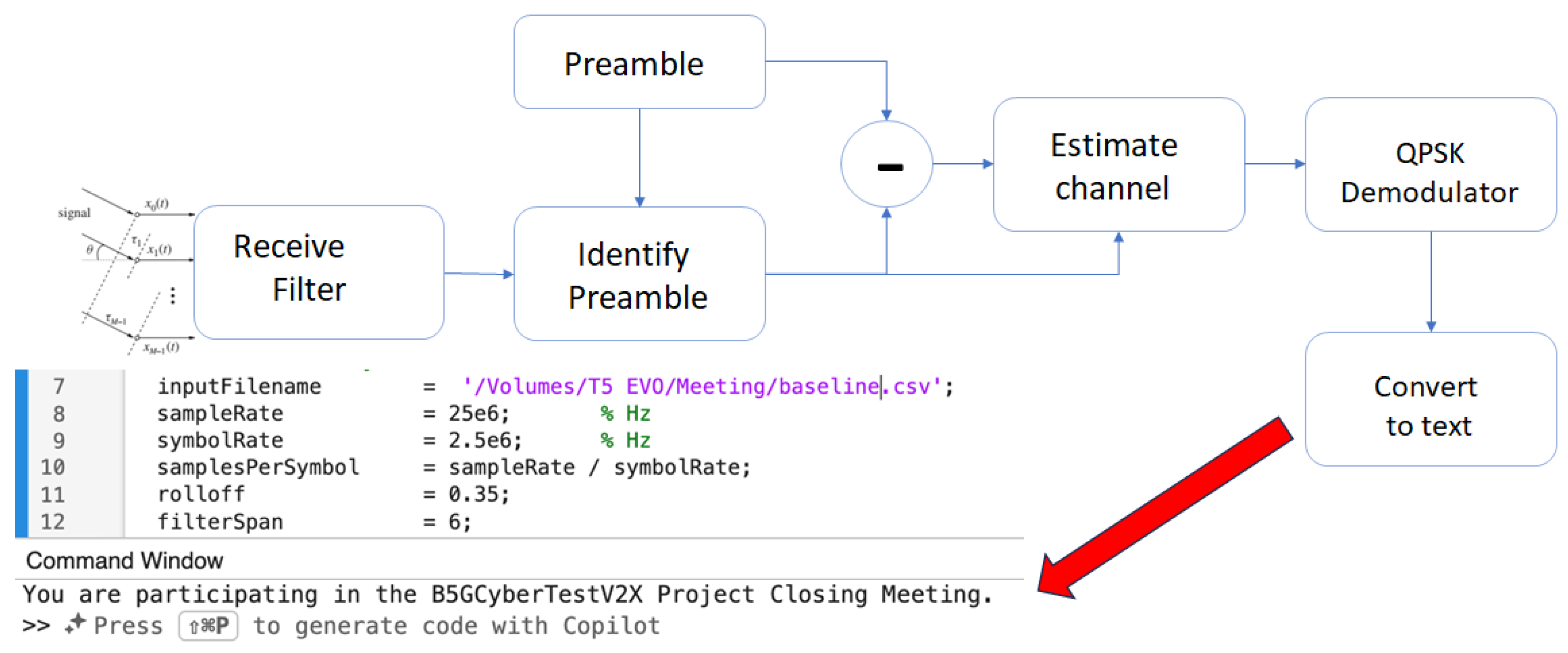
Figure 28.
Real-time spectrum with jammer (left peak) and desired QPSK transmission (right band).
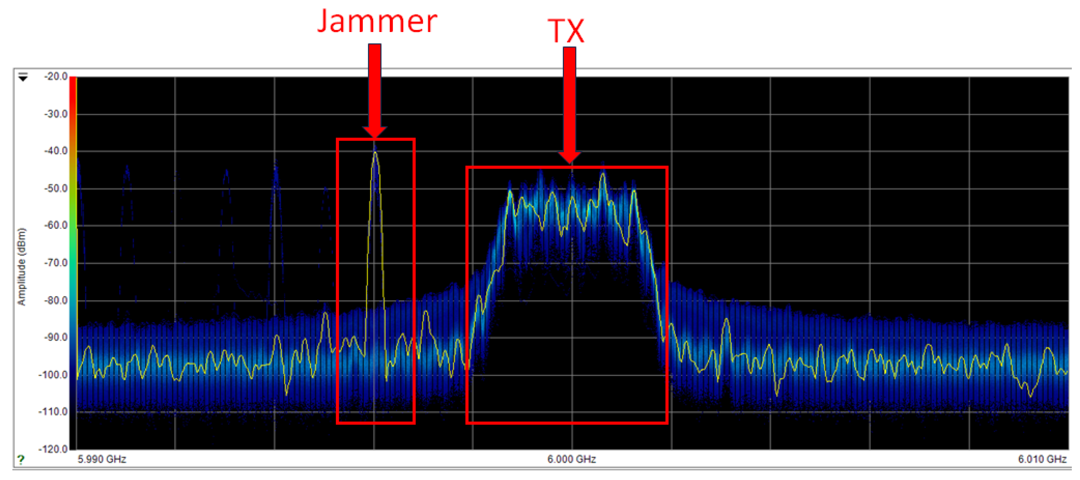
Figure 29.
Received-signal analysis under jamming: dispersed constellation, closed eye diagrams, and degraded modulation metrics.
Figure 29.
Received-signal analysis under jamming: dispersed constellation, closed eye diagrams, and degraded modulation metrics.
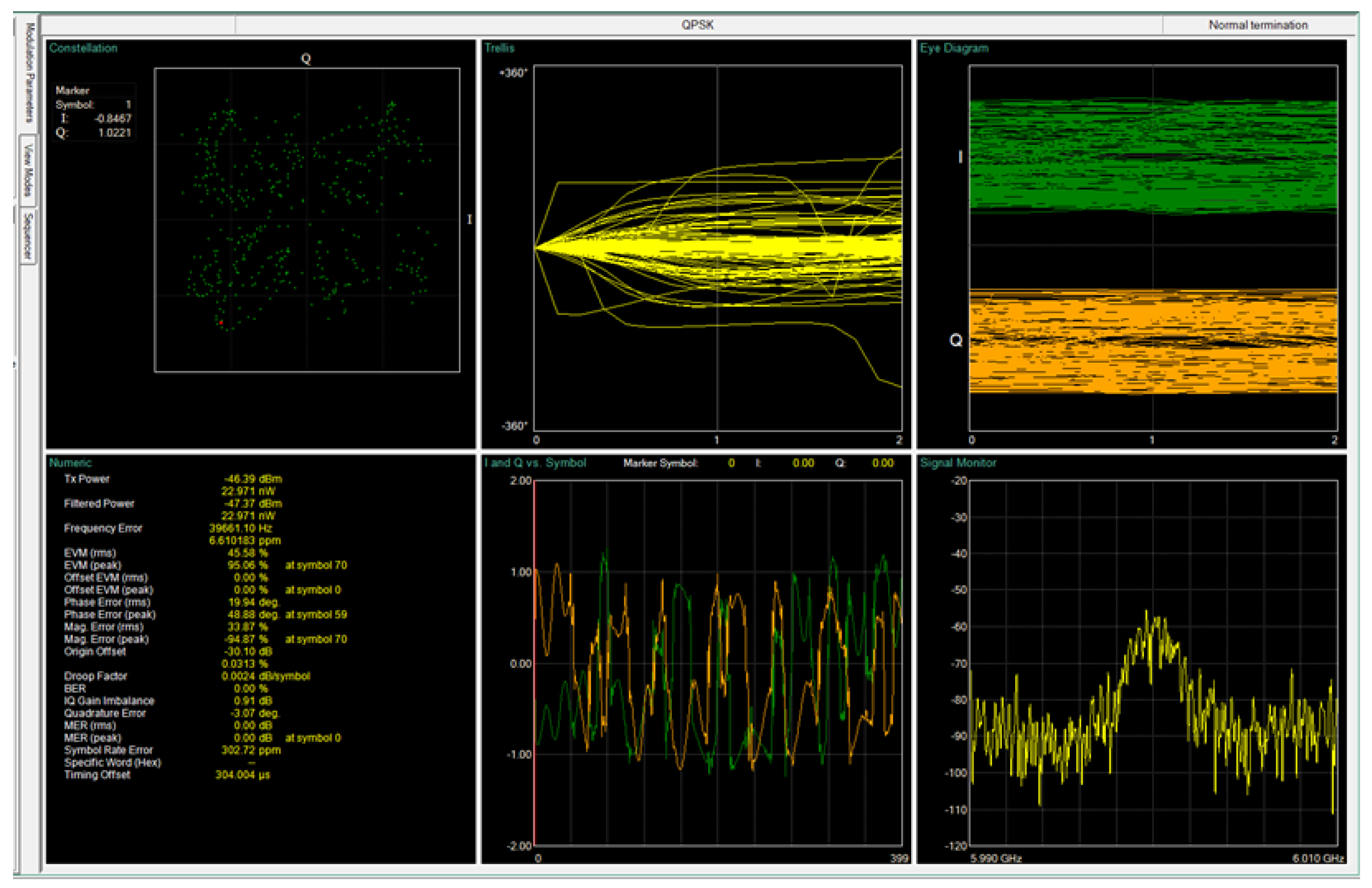
Figure 30.
Transmitted (TX) versus received (RX) constellations in the presence of jamming.
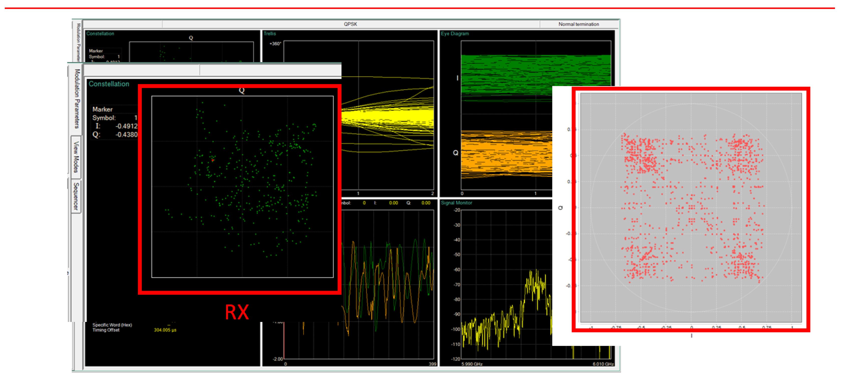
Figure 31.
Live spectrum (blue) and post-processed baseband (yellow) showing residual jammer energy after filtering.
Figure 31.
Live spectrum (blue) and post-processed baseband (yellow) showing residual jammer energy after filtering.
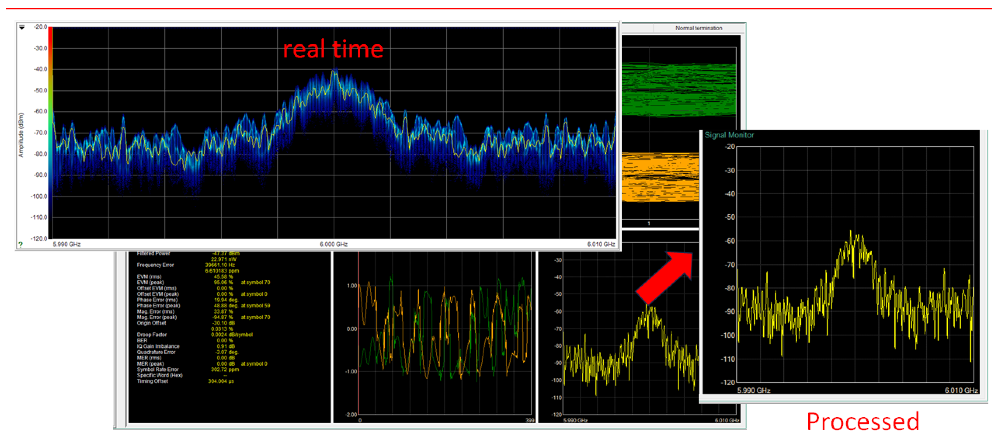
Figure 32.
Decoding pipeline under interference: corrupted byte stream after QPSK demodulation confirms message loss.
Figure 32.
Decoding pipeline under interference: corrupted byte stream after QPSK demodulation confirms message loss.
Disclaimer/Publisher’s Note: The statements, opinions and data contained in all publications are solely those of the individual author(s) and contributor(s) and not of MDPI and/or the editor(s). MDPI and/or the editor(s) disclaim responsibility for any injury to people or property resulting from any ideas, methods, instructions or products referred to in the content. |
© 2025 by the authors. Licensee MDPI, Basel, Switzerland. This article is an open access article distributed under the terms and conditions of the Creative Commons Attribution (CC BY) license (http://creativecommons.org/licenses/by/4.0/).
Copyright: This open access article is published under a Creative Commons CC BY 4.0 license, which permit the free download, distribution, and reuse, provided that the author and preprint are cited in any reuse.


