
Submitted:
07 July 2025
Posted:
09 July 2025
You are already at the latest version
Abstract
To improve the cruising range of new energy vehicles, this paper proposes a minimum loss torque ratio control strategy for permanent magnet synchronous motors (PMSMs), which is based on a controllable loss parameterized model. The research conducts a systematic investigation into how external environmental factors affect the performance characteristics of key motor components, including copper windings, iron cores, and permanent magnets. Particular attention is given to the influence of stator and rotor temperatures as well as the skin effect. Based on these findings, analytical methods for calculating copper and iron losses are formulated. Utilizing these methods, a parameterized loss model is developed that is capable of adapting to complex and variable operating conditions. Building upon this model, a novel minimum loss torque ratio control strategy is introduced, which optimizes the distribution of copper and iron losses through precise adjustment of the motor’s field current, thereby significantly improving operational efficiency across the entire load spectrum. To validate the proposed model and control strategy, an experimental platform is constructed. The results confirm the accuracy and effectiveness of the approach.
Keywords:
PMSM
; efficiency optimization
; motor loss parameterization model
; minimum loss torque ratio control strategy
1. Introduction
With the increasing severity of global climate change and the energy crisis, the electric drive system of electric vehicles (EVs), as a cleaner and more efficient alternative to traditional fossil fuel vehicles, has become a critical direction for addressing environmental pollution and energy sustainability challenges. This is primarily due to its advantages of zero emissions, low energy consumption, and high operational efficiency [1]. At the same time, continuous advancements in battery technology, motor technology, and power electronics have significantly improved the driving range, charging efficiency, and overall system reliability of pure electric vehicles. These developments have laid a solid foundation for the widespread adoption of electric drive systems [2].
Currently, the main strategies for extending the driving range of pure electric vehicles include enhancing battery energy density and optimizing the energy efficiency of electric drive systems. However, given the limited prospects for a qualitative breakthrough in materials science within the near future, achieving significant improvements in battery energy density remains a major technical challenge. As a result, improving the efficiency of electric drive systems has emerged as the primary approach for addressing the range limitations of electric vehicles [3].
In the electric drive systems of electric vehicles (EVs), various technical measures have been progressively adopted to enhance operational efficiency. These primarily include five key approaches: (1) replacing traditional induction motors with permanent magnet synchronous motors (PMSMs) to reduce rotor losses; (2) employing wide bandgap silicon carbide (SiC) power devices instead of conventional insulated-gate bipolar transistors (IGBTs), thereby significantly lowering conduction and switching losses; (3) adopting more advanced cooling techniques to reduce the operating temperatures of both the motor and power components, which in turn minimizes thermal-related system losses; (4) implementing high-performance motor control strategies to further improve motor efficiency; and (5) utilizing discontinuous pulse width modulation (DPWM) technology to reduce switching losses in the driver's power components [4]. With regard to motor control strategies, maximum torque per ampere (MTPA) control has increasingly replaced the conventional id=0 control strategy. MTPA control reduces the current flowing through the motor windings, thereby decreasing copper losses and improving overall system efficiency [5]. However, traditional MTPA control focuses solely on optimizing winding current and mainly considers copper and iron losses, which limits its ability to achieve global loss optimization. Moreover, its performance is significantly affected by magnetic flux saturation and variations in motor parameters. To address these limitations, Reference [6] introduced an MTPA control strategy based on equivalent variable parameters. By eliminating the need for derivative operations on motor parameters, this approach enables precise control under varying load conditions. Compared to conventional MTPA control, it demonstrates significantly improved system performance. Reference [7] proposed an MTPA control strategy incorporating DC signal injection to mitigate copper losses in interior permanent magnet synchronous motors (IPMSMs). This method remains robust against variations in motor parameters and allows the system to rapidly converge to a stable operating point under diverse working conditions. Experimental results validate the feasibility and effectiveness of this approach. Reference [8] presented an MTPA control strategy that integrates parameter identification with variable parameters to address the issue of magnetic saturation in the d- and q-axis inductances of IPMSMs. High-frequency rotating voltage injection is employed to identify the d- and q-axis inductance parameters. Compared to fixed-parameter methods, this strategy achieves the same output torque with reduced stator current, thereby effectively minimizing motor losses.
The LMC (Loss Model-based Efficiency Optimization Control) strategy accounts for stator copper loss through the stator winding resistance (Rs), and also incorporates stator iron loss via the iron loss resistance (RFe), as illustrated in Figure 1. By optimizing the total of stator iron loss and copper loss, this approach further enhances the operational efficiency of permanent magnet synchronous motors (PMSMs). The control strategy was first proposed by scholars such as Alexander Kusko and Donald Galler [9] in the 1980s, who demonstrated that motor losses could be reduced by solving for the optimal flux linkage derived from the loss model. Subsequently, Roy S. Colby and Donald W. Novotny [10], as well as T. Sebastian and G. R. Slemon [11], established a simplified equivalent circuit for PMSMs, which laid the foundation for the development of the loss model method. Shigeo Morimoto [12] introduced a loss minimization control strategy by regulating the armature current to minimize the combined copper and iron losses of the motor. Additionally, an approximate algorithm was proposed for real-time implementation of the loss minimization control. Meifen CAO [13] applied the minimum-loss control method and experimentally verified that, under various speed and torque conditions, there exists an optimal armature current that minimizes the total copper and iron losses of the motor. PMSMs used in electric vehicles typically operate under complex environmental conditions and diverse operating scenarios, leading to variations in internal motor parameters. Traditional LMC methods estimate stator iron loss using a fixed iron loss resistance, which only yields accurate results under specific operating conditions. When the motor deviates from its rated operating point, the stator loss estimation based on a single iron loss resistance significantly diverges from the actual motor loss.
To address the limitations of traditional LMC strategies, this paper proposes a minimum loss current ratio control method based on a parameterized motor loss model. Considering the impact of load operating conditions on the internal material properties of the stator and rotor, a parameterized approach for calculating motor stator losses is introduced. This enables the development of accurate analytical models for both copper loss and iron loss under varying motor temperatures and current frequencies. Furthermore, a minimum loss torque ratio control strategy for PMSMs is presented. By dynamically adjusting the motor's optimal magnetic field, copper and iron losses are optimally distributed, thereby improving motor efficiency across the entire speed range. An experimental platform for PMSMs is established to validate the accuracy of the proposed parameterized loss calculation method and efficiency optimization control strategy through experimental data.
2. Minimum Loss Torque Ratio Control Strategy for PMSMs
The main losses in PMSMs can be classified into five fundamental categories: stator fundamental loss, harmonic stator loss, rotor permanent magnet loss, windage and friction loss, and bearing loss. Among these, stator fundamental loss represents the dominant controllable loss component, making it the primary focus of numerous studies on loss reduction and efficiency optimization. Stator fundamental loss comprises two elements: stator copper loss and stator iron loss. In particular, stator copper loss arises from the resistive power dissipation due to current flowing through the stator windings, with its magnitude predominantly influenced by the stator current. Given the effect of motor temperature variations on internal parameters, the q-axis current in PMSMs can be formulated as
where pn denotes the number of pole pairs in PMSM, Ld,q represent the d-axis and q-axis inductances, ψf(Trotor) refers to the magnetic flux linkage of the motor’s permanent magnet, which is a function of the rotor temperature. When the rotor magnet material is NdFeB, the flux linkage can be accurately approximated by a linear function within the motor's normal operating range, which can be described as
In the electric drive systems of EVs, the equivalent resistance of the motor stator winding is affected by both elevated temperatures and variations in current frequency. Specifically, an increase in winding temperature leads to a corresponding increase in resistance; furthermore, an increase in stator current frequency also results in higher equivalent resistance, primarily due to the AC skin effect. Therefore, by incorporating these interacting factors, the equivalent resistance of the motor stator winding can be expressed as
where Rdc(T0) and Rac(Tstator) denote the DC resistance an dof the motor stator winding at the reference temperature T0 and Tstator. αCu is temperature coefficient of resistivity for the stator copper windings, rCu is the radius of the winding conductor, μCu and σCu are the magnetic permeability and electrical conductivity of winding material. δCu refers to the skin depth, which depends on the stator current frequency fcurrent.
Therefore, based on Ohm's Law and derived from Equations (1) to (3), the parametric model of motor stator winding loss under complex operating conditions can be mathematically expressed as
As shown in Equation (5), the stator copper loss of the motor is affected by multiple factors when the combined effects of temperature and winding current frequency on motor parameters are considered. However, under a fixed operating condition, the sole controllable variable is the stator current id Therefore, it can be concluded that the motor's copper loss can be effectively controlled by adjusting the stator current id.
The stator iron loss in a motor can be categorized into hysteresis loss, eddy current loss, and stray loss according to the underlying mechanisms of loss generation. Based on the Bertotti iron loss model, the core loss per unit volume is formulated as the sum of these distinct loss components.
where Bm denotes the magnetic flux density e, kh represents the hysteresis loss coefficient of ferromagnetic materials, ke and kc corresponds to the additional loss coefficient and eddy current loss coefficient. It should be noted that the values of the latter two coefficients are dependent on the alternating frequency of the magnetic field. When the effect of the skin phenomenon on the eddy current loss coefficient is considered, the functional relationship between kc and the magnetic field frequency can be expressed as
where ρiron, μiron and σiron represent the mass density, magnetic permeability and electrical conductivity of ferromagnetic materials, respectively, and diron is the thickness of the laminations.
In PMSMs, the structural differences between the stator teeth and the stator shaft result in distinct distributions of magnetic flux density within these components. Therefore, it is necessary to apply the magnetic circuit method separately for each component, incorporating the geometric parameters of the stator structure and the stator voltage equation, in order to accurately calculate the magnetic flux density. Based on the stator voltage equation, further analysis can be carried out to derive
where St and Sydenote the geometric cross-sectional areas of the stator teeth and yoke, respectively; αi represents the pole arc coefficient, and Q indicates the total number of stator slots.
According to Equations (6) to (9), the key parameters of the iron loss model for PMSM are affected not only by the temperatures of the stator and rotor, but also by the frequency of magnetic field variations. Considering the impact of temperature on the performance characteristics of the motor's ferromagnetic and permanent magnet materials, and based on the Bertotti iron loss model, the stator iron loss induced by high-frequency alternating magnetic fields under the wide temperature range conditions associated with new energy vehicle applications can be expressed as:
where kee(wr) denotes the equivalent loss coefficient of the stator additional loss, with its variation characteristics closely correlated to the motor's design parameters and operating conditions. The mathematical expression can be formulated as:
khce(ωr,Tstator) is the fundamental equivalent hysteresis and eddy current loss coefficient of the stator in a PMSM at stator temperature Tstator, and can be expressed as:
where N1 represents the number of turns per phase winding in the PMSM, Kdp1 is the fundamental winding factor of the motor, St and Sy correspond to the average cross-sectional areas of the stator teeth and stator yoke, respectively.
Based on Equations (5) and (10), the controllable loss of PMSMs can be mathematically expressed as follows when variations in the internal material parameters are taken into consideration.
As demonstrated in Equation (13), the controllable loss in PMSMs is influenced by a set of interrelated factors. Specifically, fluctuations in stator and rotor temperatures induce variations in the material properties within the motor. Moreover, the motor’s operating frequency affects the electrical conductivity of the materials due to the skin effect, consequently influencing the magnitude of the controllable loss. Nevertheless, under defined operating conditions where the motor temperature, rotational speed, and output torque are held constant, the controllable loss is exclusively determined by the field current id. Consequently, this study proposes a minimum-loss torque ratio control strategy for PMSMs that applies across the entire operational range, based on an established parametric loss model.
This research formulates a parameterized mathematical model to characterize controllable losses in IPMSMs, utilizing motor temperature, rotational speed, and output torque as input variables. The optimal idopt, which minimizes total motor losses, is determined based on Equation (13). Through continuous adjustment of the -axis current to track idopt, the proposed method facilitates an optimized distribution between copper loss and iron loss. From a system-level optimization standpoint, the approach ensures minimal motor losses while maintaining consistent output performance across the full operational range.
The permissible range of the optimal d-axis current idopt in PMSMs is governed by the reliability specifications of the drive system. Primarily, to ensure operational reliability, the optimal d-axis current must be maintained below the maximum demagnetization current of the rotor’s permanent magnets, which can be mathematically expressed as:
where id_permanent_magnet_max denotes the maximum demagnetization current of the rotor-mounted permanent magnet in PMSMs.
Secondly, the optimal d-axis current idopt in PMSMs is subject to constraints imposed by the hardware limitations of the drive controller. To ensure reliable motor operation, the phase current must remain within the maximum allowable current limit defined by the driver specifications, thereby preventing potential damage to the power electronic components. Accordingly, the optimal d-axis current must satisfy the following constraint:
where Is_max denotes the maximum permissible motor current under the hardware limitations imposed by the motor driver
For the salient-pole PMSM, in which the d-axis and q-axis inductances are identical, the optimal d-axis current idop must satisfy
3. Experimental Results and Discussion
To validate the accuracy of the parametric loss calculation method and the minimum loss torque ratio control strategy for permanent magnet synchronous motors (PMSMs) across the full operational range, as proposed in this study, a back-to-back motor test platform was implemented within a temperature-regulated environmental chamber capable of simulating both high- and low-temperature conditions (refer to Figure 2). Comprehensive experimental measurements and analyses were performed on the motor's operational characteristics under diverse operating scenarios to evaluate the effectiveness and robustness of the proposed approaches.
The parameters of PMSM under test are summarized in Table 1.
At a controlled temperature of 30°C, the loss characteristics of PMSM under various operating conditions are experimentally studied. The resulting data is compared with the values calculated by the loss parameterization model, which are illustrated in Figure 3.
As illustrated in Figure 3, the motor loss parameterization model developed in this paper accurately characterizes the variation patterns of motor losses under various operating conditions, thereby facilitating precise computation of losses across the entire operational spectrum. To validate the model's accuracy, experimental loss data under rated speed and rated torque conditions are compared with the simulation results generated by the parameterization model, as depicted in Figure 4.
As illustrated in Figure 4, the analytical loss model for the PMSM proposed in this study maintains an estimation error of motor losses within ±5% across all tested operating conditions. The maximum deviation occurs under the low-speed no-load condition; however, this operating point lies outside the primary operational range of the electric vehicle drive system. These findings demonstrate that the proposed model possesses high accuracy, reliability, and practical applicability for real-world applications.
To thoroughly investigate the loss characteristics of PMSMs, this paper conducts comprehensive testing and analysis under extreme temperature conditions. Specifically, the motor's loss behavior across a wide range of operating conditions is systematically evaluated at ambient temperatures ranging from -55 °C to 85 °C. A comparison between the experimental results and the model-predicted values is presented in Figure 5.
Through systematic experimental data of motor losses under varying temperature conditions, it is evident that the loss characteristics of PMSMs across different operating conditions exhibit a strong correlation with ambient temperature. Research indicates that the motor's iron loss increases as temperature decreases, demonstrating a distinct negative temperature coefficient behavior, whereas copper loss increases with rising temperature, following a positive temperature coefficient trend. These findings are in excellent agreement with the theoretical analysis presented in the preceding section. Moreover, a comparative analysis of Figures 4-10(a) and 4-10(b) confirms that the proposed loss model achieves high predictive accuracy across multiple operating conditions, enabling precise calculation of the motor's loss characteristics. A focused evaluation of the loss data under rated speed and torque conditions from Figure 4-18 provides a direct comparison between experimental results and model predictions, which is shown in Figure 6.
As shown in Figure 6, the proposed analytical motor loss model proposed demonstrates strong applicability and high accuracy across a broad range of temperature conditions. The model effectively characterizes the variation of motor losses with respect to speed and torque within a temperature range spanning from -55°C to 85°C. Across the entire operational spectrum, the maximum estimation error remains below ±6%, confirming the model's robust predictive performance. It is important to note that the observed estimation deviations are predominantly associated with low-speed no-load conditions, which are not representative of typical operating scenarios for EVs. Therefore, the proposed analytical motor loss model holds substantial practical value for enhancing the efficiency control performance of PMSMs under the complex operating conditions prevalent in electric vehicles, thereby substantiating its reliability and engineering applicability.
Based on the experimental platform shown in Figure 2, this study carries out comprehensive testing and analysis to evaluate the minimum loss torque ratio optimization control strategy, which is grounded in the loss parameterization model, under a range of temperature conditions. The experimental results confirm the effectiveness of the proposed high-performance motor control strategy in enhancing operational efficiency across diverse thermal environments, which is shown in Figure 7.
Due to the high computational complexity of the analytical motor loss parameterization model proposed in this study, deriving an explicit analytical solution for the optimal current idopt remains impractical for multi-parameter PMSMs. To overcome this limitation, this research integrates the material properties and electromagnetic design parameters of the motor with the theoretical framework established in Equations (14) to (16), and applies the genetic algorithm to perform offline computation of the optimal current corresponding to controllable motor losses under a wide range of operating conditions. A comprehensive mapping table has been constructed to characterize the relationships among speed, torque, and the optimal current idopt across varying temperature conditions. During real-time control, the d-axis current is dynamically adjusted to track the optimal current idopt by referencing this precomputed mapping table, thereby achieving optimal motor loss distribution and significantly improving overall system efficiency.
As illustrated in Figure 8, the motor efficiency optimization control strategy based on the wide-temperature-range loss model proposed in this study exhibits significant advantages over conventional control approaches across the complex environmental temperature range typical of electric vehicle applications. Experimental results demonstrate that under rated operating conditions, motor efficiency improves from 90.2% to 91.0%, reflecting a 0.8% increase. Under high-speed light-load conditions, the efficiency rises from 70.1% to 72.8%, representing a 2.7% enhancement. These findings provide compelling evidence for the effectiveness of the proposed strategy in improving the performance of electric vehicle drive systems and reducing overall energy consumption.
Further analysis of Figure 8 reveals that as ambient temperature decreases, the resistance of the stator winding diminishes while the residual magnetism of the permanent magnet increases. This results in reduced copper losses and increased stator iron losses under equivalent operating conditions. Concurrently, the difference between copper loss and both iron loss and rotor eddy current loss becomes more pronounced. This systematic variation underscores the superior ability of the loss model-based control strategy to simultaneously optimize iron and copper losses, with particularly notable efficiency gains observed under low-temperature conditions.
4. Conclusions
This paper addresses a critical limitation in conventional control strategies for PMSMs, which typically focus on efficiency optimization under isolated or static operating conditions. To overcome this limitation, an innovative parametric method for calculating motor losses is proposed. This method systematically incorporates the influence of internal parameter variations—specifically stator temperature, rotor temperature, and current frequency—on the material properties of key motor components, including copper conductors, iron core laminations, and permanent magnets. Based on this comprehensive analysis, a controllable parametric analytical model for motor losses is developed, enabling accurate loss prediction under complex and dynamic operating conditions. Furthermore, a minimum loss torque ratio control strategy is introduced to achieve optimal performance across the entire operational range. By modulating the motor's magnetic field, the proposed strategy facilitates the re-optimization and balanced redistribution of copper and iron losses, thereby maximizing overall efficiency across the full speed and load spectrum.
Author Contributions
Formal analysis, Pengcheng Du; Methodology, Qingbo Guo and Wei Cai; Software, Tongfei Sheng; Validation, Minghao Zhou and Chaoyu Zhang; Writing – original draft, Bowen Gao; Writing – review & editing, Chengming Zhang.
Funding
This research was funded by China Postdoctoral Science Foundation,grant number 2021M701018.
Data Availability Statement
The data presented in this study are available on request from the corresponding author due to commercial reasons.
Acknowledgments
During the preparation of this manuscript/study, the authors used Deepseek for the purposes of language editing and enhancement. The authors have reviewed and edited the output and take full responsibility for the content of this publication
Conflicts of Interest
The authors declare no conflicts of interest. The funders had no role in the design of the study; in the collection, analyses, or interpretation of data; in the writing of the manuscript; or in the decision to publish the results.
References
- Wen, B.; Liu, K.; Zhou, J.; Zhou, S.; Hu, W.; Chen, Y.; Huang, C.; Huang, Q. Real-Time Estimation of PMSM Rotor Flux Linkage for EV Application under Steady State and Free-Running Conditions. World Electr. Veh. J. 2022, 13, 83. [CrossRef]
- Aiso, K.; Akatsu, K. Performance Comparison of High-Speed Motors for Electric Vehicle. World Electr. Veh. J. 2022, 13, 57. [CrossRef]
- Breban, S.; Dranca, M.; Chirca, M.; Pacuraru, A.-M.; Teodosescu, P.-D.; Oprea, C.-A. Experimental Tests on a Spoke-Type Permanent Magnets Synchronous Machine for Light Electric Vehicle Application. Appl. Sci. 2022, 12, 3019. [CrossRef]
- Wu, Y.; Wu, Z. A Generalized Center-Aligned High-Resolution Pulse Width Modulator Implementation Using an Output Serializer in Field Programmable Gate Arrays. Actuators 2025, 14, 181. [CrossRef]
- Dianov, A.; Anuchin, A. Design of Constraints for Seeking Maximum Torque per Ampere Techniques in an Interior Permanent Magnet Synchronous Motor Control. Mathematics 2021, 9, 2785. [CrossRef]
- G. Bertotti, P. Mazzetti, G.P. Soardo. A general model of losses in soft magnetic materials. Journal of Magnetism and Magnetic Materials 1982, 26, 3. [CrossRef]
- Naomitsu Urasaki, Tomonobu Senjyu. Investigation of influences of various losses on electromagnetic torque for surface-mounted permanent magnet synchronous motors. IEEE Transactions on Power Electronics 2003, 18, 1. [CrossRef]
- Zhou, Z.; Gu, X.; Wang, Z.; Zhang, G.; Geng, Q. An Improved Torque Control Strategy of PMSM Drive Considering On-Line MTPA Operation. Energies 2019, 12, 2951. [CrossRef]
- Kusko A, Galler D. Control Means for Minimization of Losses in AC and DC Motor Drives. IEEE Transactions on Industry Applications, 1983, IA-19, 4. 8. [CrossRef]
- Colby R S, Novotny D W. Efficient Operation of Surface-Mounted PM Synchronous Motors. IEEE Transactions on Industry Applications, 1987, IA-23, 64. [CrossRef]
- Sebastian T, Slemon G, Rahman M. Modelling of permanent magnet synchronous motors. IEEE Transactions on Magnetics, 1986, 22,5. [CrossRef]
- Morimoto S, Tong Y, Takeda Y, et al. Loss minimization control of permanent magnet synchronous motor drives. IEEE Transactions on Industrial Electronics, 1994, 41(5): 511-517. [CrossRef]
- Cao M, Hoshi N. Electrical loss minimization strategy for interior permanent magnet synchronous motor drives. 2010 IEEE Vehicle Power and Propulsion Conference, 2010,. [CrossRef]
Figure 1.
Mathematical model of a permanent magnet synchronous motor with iron loss resistance.
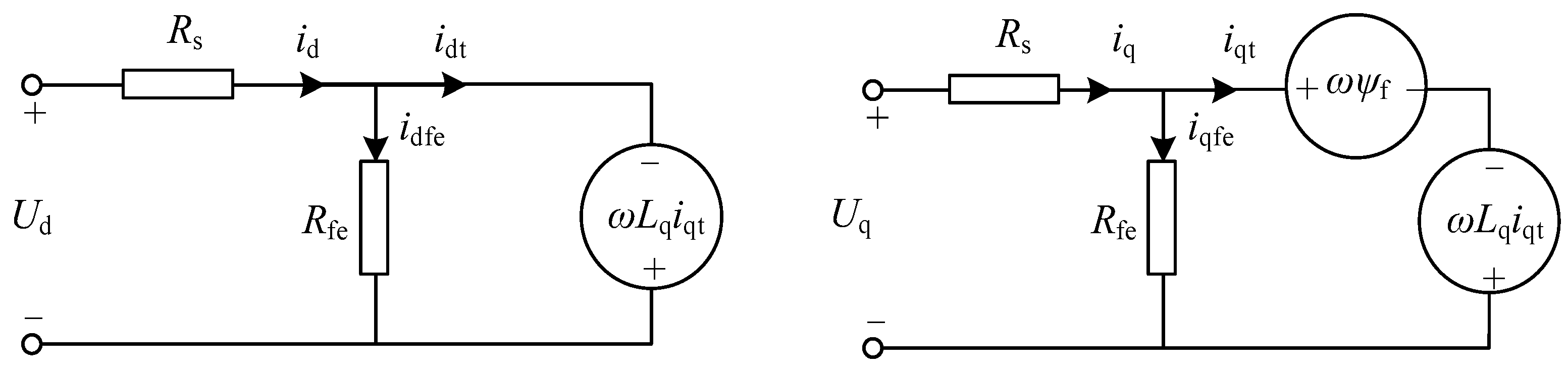
Figure 2.
test platform for PMSM drive system in the experimental cabins.
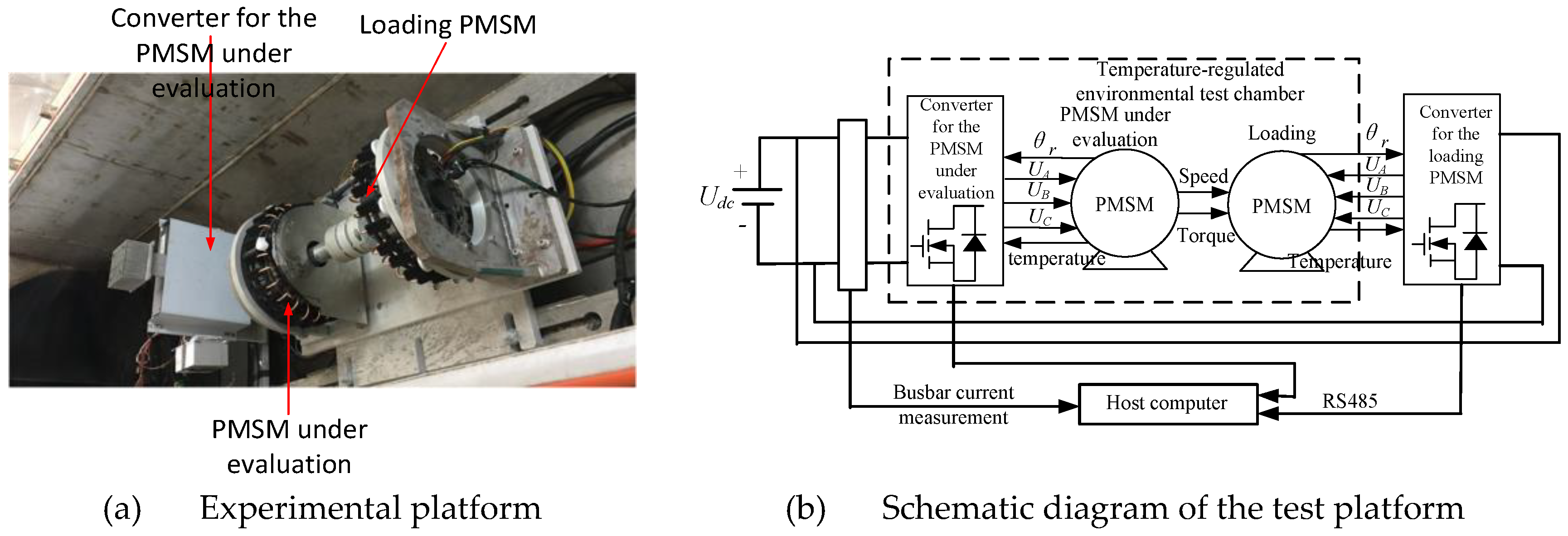
Figure 3.
Test data of motor loss and estimation loss of analytic motor loss model at 30℃.
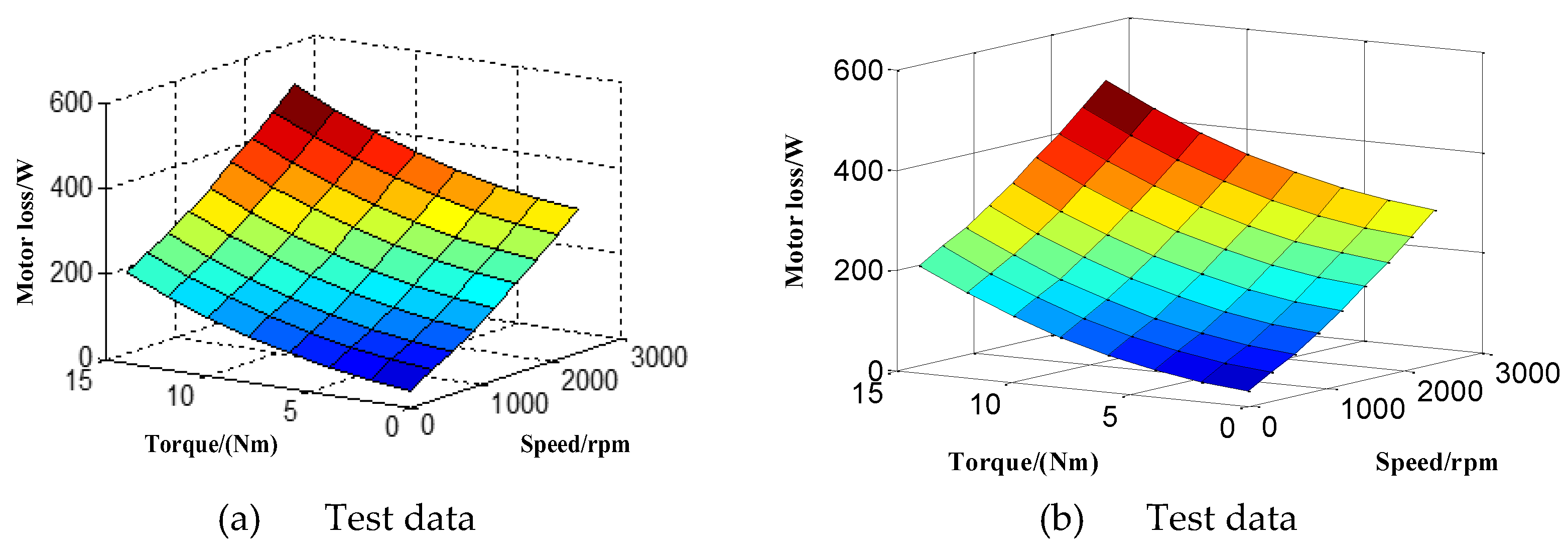
Figure 4.
Test data and calculation loss of PMSM at different operation condition at 30℃.
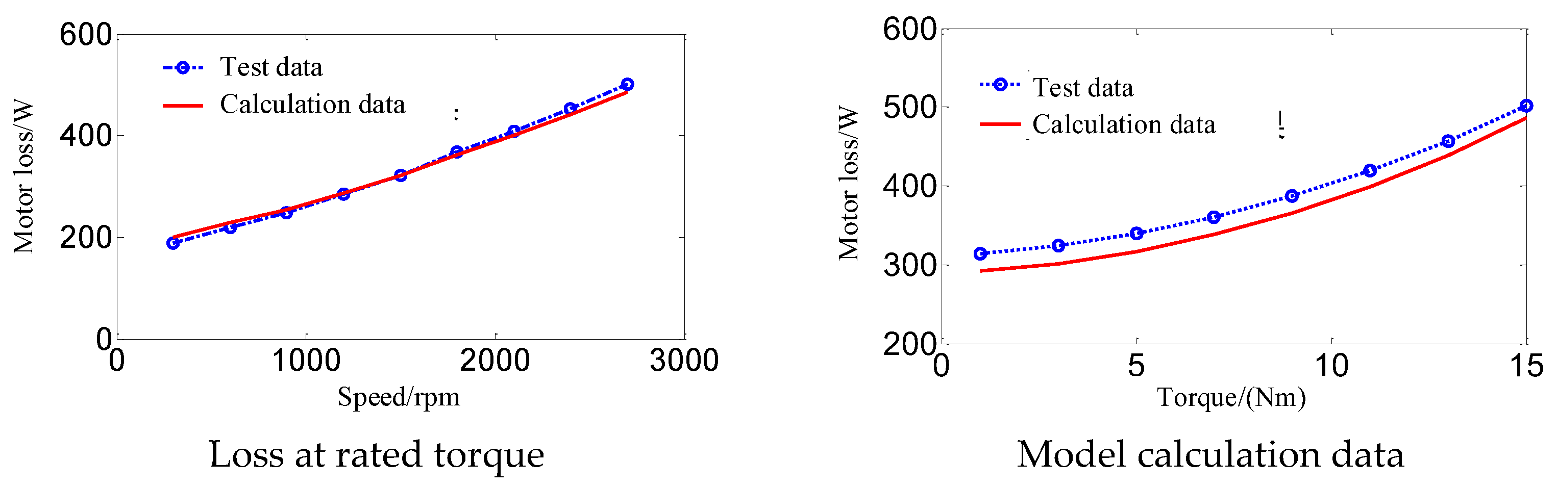
Figure 5.
Test data of motor loss and calcuation loss of analytic motor loss model from -55 °C to 85 °C.
Figure 5.
Test data of motor loss and calcuation loss of analytic motor loss model from -55 °C to 85 °C.
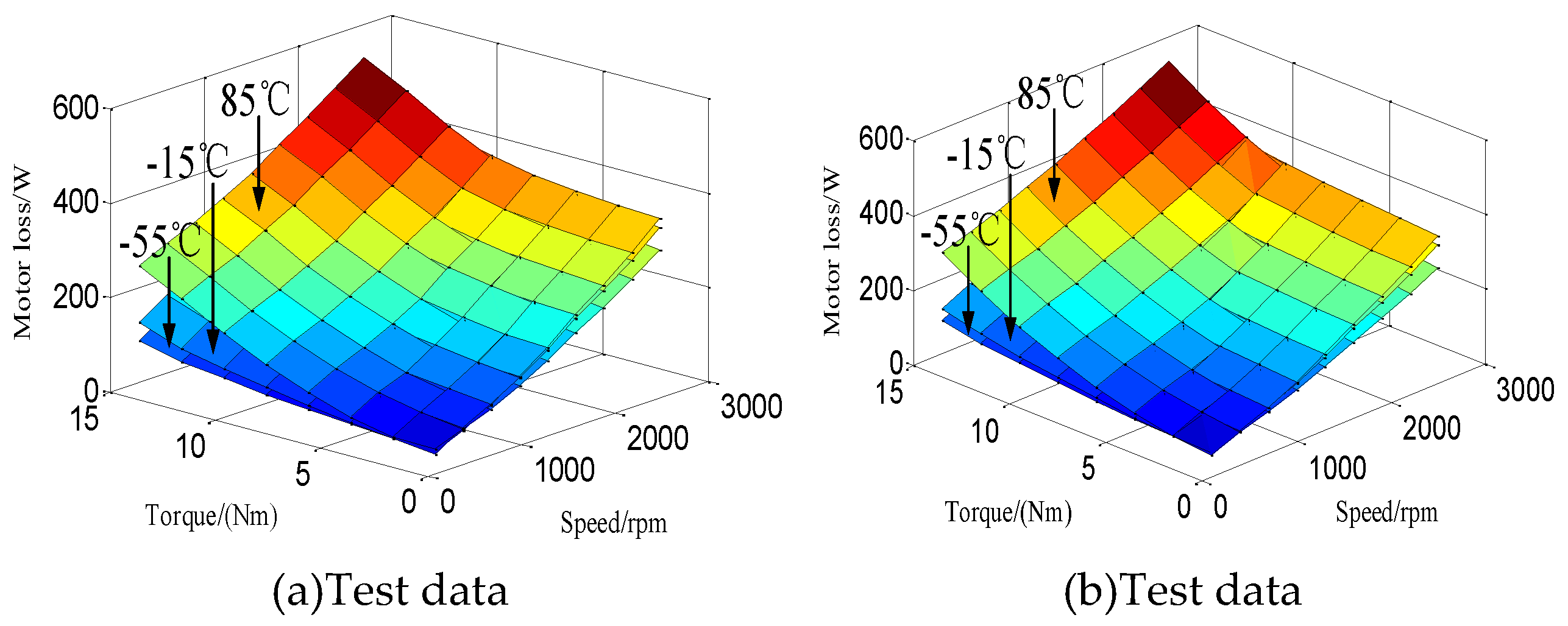
Figure 6.
Test data of motor loss and calculation loss of proposed analytic motor loss model from -55 °C to 85 °C.
Figure 6.
Test data of motor loss and calculation loss of proposed analytic motor loss model from -55 °C to 85 °C.
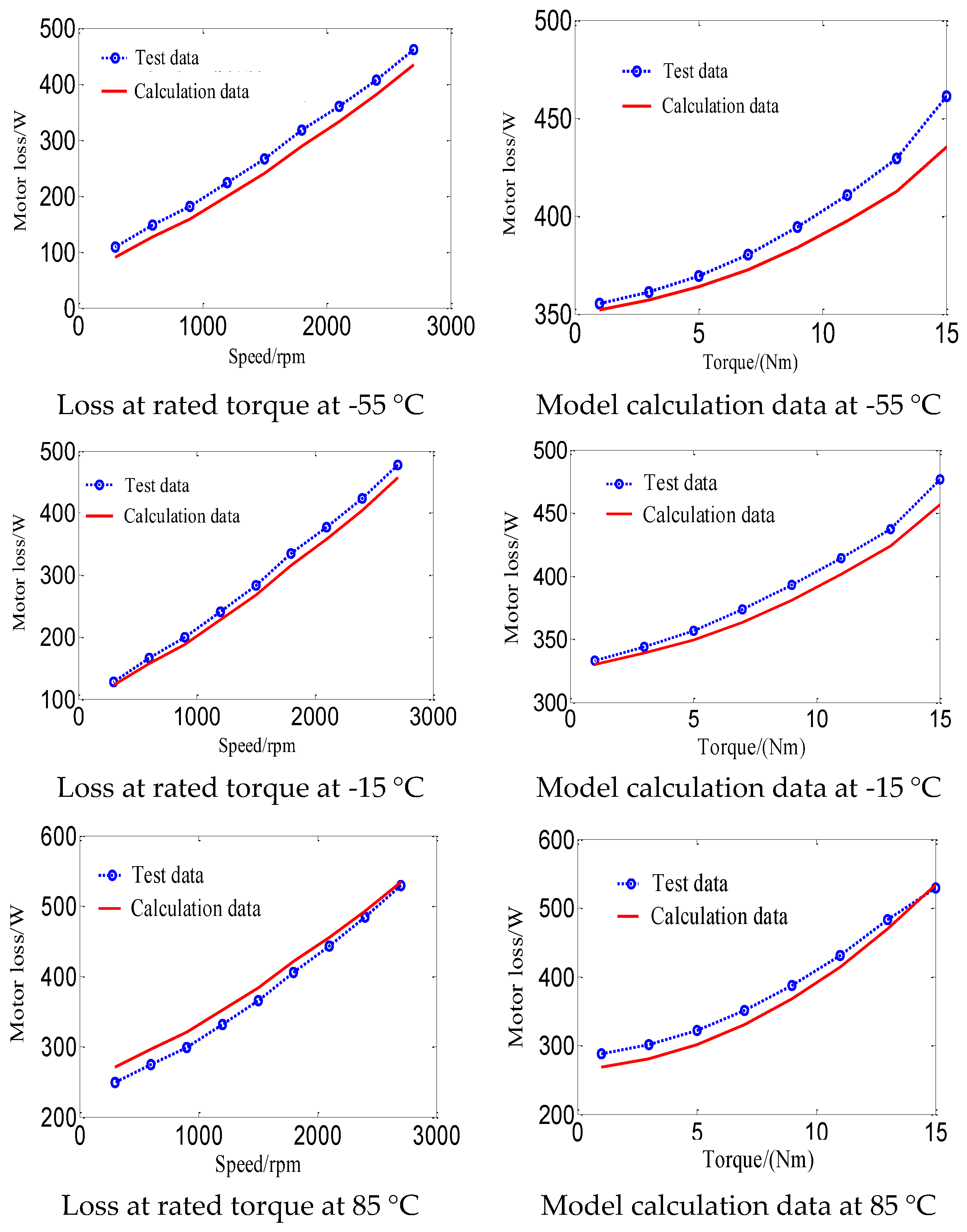
Figure 7.
Test data of motor efficiency with traditional control strategy and proposed efficiency optimization control strategy.
Figure 7.
Test data of motor efficiency with traditional control strategy and proposed efficiency optimization control strategy.
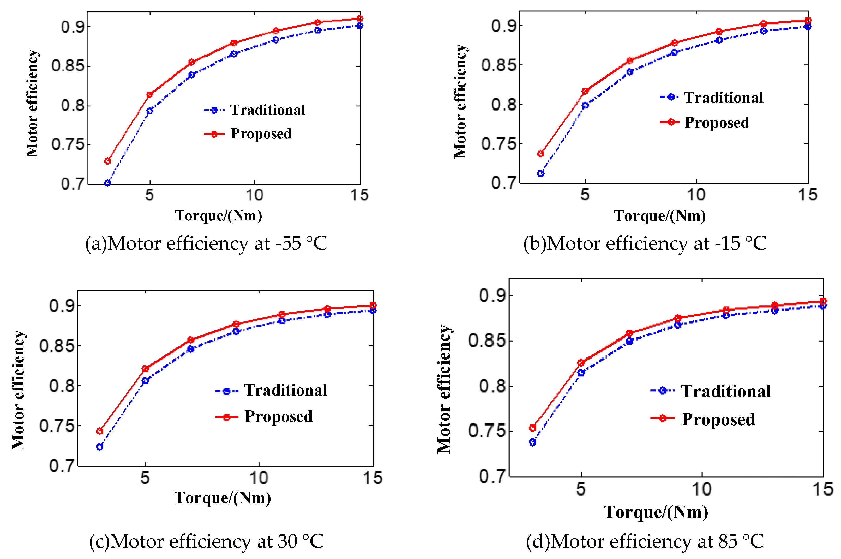

Table 1.
Parameters of 4kW permanent magnet synchronous motor.
| Parameter | Value | Parameter | Value |
|---|---|---|---|
| Rated speed | 2700rpm | Rated power | 4kW |
| Rated Torque | 15N·m | Number of pole pairs | 10 |
| Number of slots | 24 | Inductance | 1.2mH |
| Resistance | 0.108Ω | PM flux linkage | 0.0488 Wb |
Disclaimer/Publisher’s Note: The statements, opinions and data contained in all publications are solely those of the individual author(s) and contributor(s) and not of MDPI and/or the editor(s). MDPI and/or the editor(s) disclaim responsibility for any injury to people or property resulting from any ideas, methods, instructions or products referred to in the content. |
© 2025 by the authors. Licensee MDPI, Basel, Switzerland. This article is an open access article distributed under the terms and conditions of the Creative Commons Attribution (CC BY) license (http://creativecommons.org/licenses/by/4.0/).
Copyright: This open access article is published under a Creative Commons CC BY 4.0 license, which permit the free download, distribution, and reuse, provided that the author and preprint are cited in any reuse.


