Submitted:
02 July 2025
Posted:
03 July 2025
You are already at the latest version
Abstract
The Rotating Liner Engine (RLE) is a design concept where the cylinder liner of a heavy-duty Diesel engine rotates at about 2-4 m/s surface speed to eliminate the piston ring and skirt boundary friction near the top and bottom dead center. Two single cylinder engines are prepared using the Cummins 4BT 3.9 platform, one is RLE, the other is baseline (BSL), i.e. conventional. In 2022, we published the test results of the RLE under load, but we lacked detail test data for the baseline. In this new set of experiments, we compare the RLE performance at idle and under load of up to about 7 bar IMEP (indicated mean effective pressure) to the baseline under similar conditions. It has been proven that the elimination of metallic contact between the compression rings and cylinder wall takes place with a liner speed of 1.5-2.3 m/s surface speed (283-426 rpm for the 102 mm bore) for the 850-1280 rpm crankshaft speed. The RLE FMEP is substantially reduced under load, which is a trend opposite to standard engines.
The total reduction of FMEP for idle and medium load is measured to be 0.4 and 0.8 bar respectively. When the above results are applied to complete rather than the modified single cylinder engine application, the combined fuel efficiency benefit is approximated to a fuel consumption reduction of 33 % at idle and up to 10 % for medium loads and speeds. Minimization of cylinder and piston ring wear is expected. One significant observation from the research is that the piston rings and skirt boundary friction is a dominating factor in the friction losses of the modern diesel engine. We have not yet operated the two engines under forced air induction, but we expect the RLE benefit to be approximately double the 0.8 bar measured benefit of the naturally aspirated engines. Extrapolating the experimental results to a 20 bar BMEP bring fuel economy improvement to over 7 %.
Keywords:
engine friction
; engine lubrication
; engine wear
; piston assembly friction
; diesel engine thermal efficiency
1. Introduction
The contribution in engine friction is very significant in the overall efficiency of the engine. There are many studies in the literature that analyse piston friction, and they are not in general agreement about the magnitude. The experimental work is generally the most accurate, and this has been done in many ways. The first attempt to measure overall friction was by Gish 1958 [4] where the total friction was measured in a spark ignition engine in the IMEP minus BMEP method (same method as in this paper). In fact, this is the first time that friction was measured accurately, and a very useful definition of terms separating mechanical friction from pumping losses has been expanded for the first time. It was found that the friction at constant speed is a strong function of peak cylinder pressure, and this was mostly attributed to the piston rings close to TDC. Similar findings were done by Chen [2] (1965) and interestingly enough, the term of the friction that is directly linked to pressure loading is very similar in magnitude in modern engines. More extensive literature review with respect of friction and wear is described by Dardalis (2012) [6] and Dardalis (2019) [7]. Furthermore, as modern diesel engines are equipped with Exhaust Gas Recirculation (EGR) in order to reduce NOx emission losses, the issue of cylinder corrosive wear becomes even more critical (Takakura et al. 2025 [20]).
The RLE concept was inspired by the historic Sleeve Valve Engines (SVEs), where a moving cylinder sleeve (liner) replaced the conventional valve train, and the cylinder sleeve rotated briefly around TDC compression/expansion. The most well-known versions of the SVEs were large high BMEP aircraft engines used during WWII and beyond. The tribology and geometry of the SVEs were extensively described by Ricardo et al. [18] and Dardalis et al. [6], and only a summary will be repeated here. It was discovered that the cylinder rotation in the proximity of TDC eliminated the wear pattern in the TDC area that existed in conventional engines of the era, and is also formed in engines today. Even though no detailed FMEP studies were carried out, the SVEs exhibited low friction as established by motoring tests and by good fuel efficiency at high BMEP when compared with equivalent conventional engines. Even back then it was well known that the collapsed hydrodynamic lubrication in proximity to TDC is responsible for a high portion of mechanical friction. The developers suspected that this friction term was either eliminated or considerably reduced in their engines, but they never attempted to prove the theory. Fedden (1938) [10] measured the difference in FMEP between an SVE and a conventional engine under firing conditions, and the difference in FMEP (obtained by the advantage in BMEP by the SVE) is very similar in magnitude to the measurements presented in this paper.
The current prototype design, as described by Dardalis et al. [6] and the prototype hardware as described by Dardalis et al. [7] is a single cylinder based on the 4 cylinders Cummins 4BT (102 mm bore, 120 mm stroke) where only cylinder 2 is active, and the rest of the pistons have been removed and replaced by bob weights. This engine was selected for conversion because it is relatively small and inexpensive, but also features many characteristics of heavy-duty engines such as deep skirted pistons and large crankshaft bearings. The reader is strongly encouraged to review our prior publications to achieve a thorough understanding of the concept and its geometry. Also, the three independent measurements in establishing the idle fuel economy benefit were presented in Dardalis et al. [6], and the readers are strongly encouraged to read this publication.
The prototype design is such that the complete engine could be modified, but only cylinder # 2 was modified in the current design, and only the piston on the #2 cylinder is present. The operation is naturally aspirated as a single cylinder engine cannot support a turbocharger, but in the future, we plan to use an externally driven supercharger. The crankshaft drives the rotating liner via an external V-belt and pulley - the ratio of the crank to rotating liner revolutions is 3:1. This ratio was selected based on the sleeve valve engine experience, and can be revised (perhaps reduced oil viscosity will require higher liner speeds). The face seal between the cylinder head and the rotating liner that contains the combustion gas with negligible gas leakage, very low friction, and zero wear. This sealing mechanism is the key to the RLE technology. A floating primary sealing ring with no end-gap acts axially against the top of the rotating liner flange. Conceptually, the seal functions like an axial piston ring, as the gas pressure closing force acts axially against the rotating liner flange rather than radially against the cylinder as in a piston ring. Hydrodynamic step pad features are provided so that the liner rotation generates hydrodynamic pressure which prevents the primary sealing ring and liner from contacting. Additional lubricant passages from the block vertical oil gallery have been generated, so that the seal interface is lubricated and cooled. This oil flow returns to the oil sump. Much like an oil control piston ring, a relatively high spring force acting on the primary sealing ring ensures that the film thickness is relatively small when the gas pressure is low (the exhaust and intake strokes), in order to achieve oil control. The fact that a mechanical face seal can operate under high pressure with no metal-to-metal contact has been extensively proven by Lebeck [14,15,16]. More details on the seal design can be found on Dardalis 2012 et al. [6]. The sealing mechanism achieves negligible blowby (no carbon deposits in the area ever detected) with no wear and has been functioning satisfactorily for at least 100 hours of running. Dardalis 2012 et al. [6] estimated acceptable minimum film thickness for up to 180 bar peak pressure). In the work presented here, dynamometer-loaded tests were conducted, showing that the engine can handle at least up to about 7.5 bar IMEP, and with about 70-75 bar peak pressure under continuous operation, with no signs of distress or leakage. Under transients with more advanced injection timing, we have seen a peak pressure of about 100 bar. Figure 1 shows a conceptual conversion of a complete Cummins ISB. The geometry can easily fit most heavy-duty engines in production today.
An additional noteworthy design detail are the three journal bearings that support the rotating liner for piston side loads. The stationary liner on the block has been bored out in order to give necessary clearance for the 3mm thick liner. However, tight clearance typical for journal bearings is provided only in three sections, one on the very top, one in the middle, and one in the bottom. Elsewhere, the clearance is relatively large, in order to minimize viscous drag (Figure 13). An oil passage is drilled from the vertical block oil gallery to the top journal, and the resulted flow is downwards, lubricating the other two journals before it drains back to the oil pan. This oil flow also takes some of the liner cooling heat with it,
The Diesel engine is the ideal platform to be converted to the rotating liner concept. The high cylinder pressure, which is necessary for the high thermal efficiency, also causes a lot of friction. This happens even at low loads due to the high compression ratio and unthrottled operation.
Our first publication on the Diesel RLE (Dardalis et al. [6]) described the RLE and the RLE face seal design details. It also presented a method of estimating the expected fuel efficiency benefits. The estimates from that publication, with relatively conservative assumptions, and based on standard empirical diesel engine friction models were as follows:
- Idle fuel efficiency improvement of about 25%.
- Urban section of HD FTP: 9.0%.
- Overall HD FTP: 6.8%.
- Full Load: 4.0%.
However, based on current testing, the fuel economy benefits of the concept are significantly higher.
The magnitude of piston assembly friction is very high close to the TDC area and dominates over all other sources as indirectly proven by Marek [17].
Our publication in 2019 (Dardalis et al. [7]) described the single cylinder Diesel RLE prototype created by modifying a Cummins 4BT. Several photographs of key components of the prototype were provided (engine running and internal pictures available on YouTube). Also, Dardalis et al. [7] presented an elaborate literature review on the subject of the magnitude of boundary friction contribution to total engine friction, and theories of how lubricant film thickness is formed due to liner rotation, including the theory of non-parallel micro-scratch structure formation in the liner region near TDC and piston rings due to the orbital nature of the relative motion of rings/liner. In our publication in 2021 (Dardalis et al. [7]) we presented extensive documentation of the combustion characteristics of the RLE compared to a baseline engine (carrying out all the modifications necessary for single cylinder operation, except for the liner rotation). Based on the latter analysis, the overall friction reduction accomplished by the RLE on the single cylinder platform but with a 5-bearing crankshaft and accessories sized for a complete engine was about 25-30%. When extrapolated to a complete engine, the benefit in idle fuel consumption was 40% (in this paper, we have refined the BSL measurements, and the idle benefits are calculated slightly lower). While accurate FMEP measurement was not possible in the data presented by Dardalis et al. [7], the corresponding reduction of friction was of the order of 50 kPa (0.5 bar). There are two additional factors that support the very high fuel economy benefit at idle. First, the concentration of CO2 in the exhaust of the RLE prototype at the same operating temperature was substantially lower than the baseline (less than 1.5% for the RLE, over 2.5% for the BSL both readings taken at 70oC coolant and oil temperature, both reduce at higher temperatures). Second, even though the cooling system is configured in exactly the same way, the baseline requires about 30 % less time to warm up from starting temperature (around 140F or 60oC) to operating temperature (around 160F 71C). More details on the cooling system are given below in Section 2.1.
Originally, we were planning on developing our instrumentation on the baseline engine (BSL). However, as it turned out, we have operated the RLE a lot longer than the BSL, and it has operated without any major issues. The RLE has shown remarkable reliability as a laboratory test-rig engine, and in all the inspection teardowns we have performed, we did not have to replace or adjust a single component due to malfunction or wear. We see no signs of wear in all of the components. While the hours of operation of any laboratory engine are low compared to conventional heavy-duty engines, if any wear was taking place it would have left its mark on the polished sealing components. Also, we have not exceeded 7.5 bar IMEP (indicated mean effective pressure) nor 100 bar peak pressure so far. The reasons are due to the unusual behaviour of our injection pump and the impossibility of running a turbocharger with a single cylinder engine (we plan to use a supercharger in the future). The same injection pump was used for both engines. However, the analysis presented by Dardalis [6] indicates that the film thickness of the face seal will be sufficient for metallic separation for 180 bar peak pressure, with this current design, for a viscosity of 0.003 mPa-s, which is within the 10w30 oil grade at about 150 C. We are using 15w40 for all these recent tests for both engines.
One additional peculiarity of all the loaded tests presented here is the very high rate of pressure rise (up to about 25 bar per degree for the RLE, about 20 for the BSL). Our injection system is likely causing this problem. The waviness we see in the pressure signal is related to this very high rate of pressure rise. The only way to minimize this problem would be to advance the injection timing (we cannot retard the injection timing; we are almost at the end of the adjustment range), but this would cause higher cylinder pressure and premature combustion. This was nevertheless attempted, and while the peak pressure increased from 70 bar to about 75 bar, the IMPEP, FMEP, and waviness were about the same (results not presented in detail). In all the tests we are presenting, when the IMEP approaches 7 bar, our peak cylinder pressures were about 70 bar at around 1 to 2 degrees after TDC, which is too early for standard Diesel engine operation.
While this following point has been discussed in our prior publications, we need to remind the reader that the piston rings in the prototype have been pinned and cannot be rotated by the liner at any time. However, even if they were not pinned, the high pressure would hold the compression rings fixed (but possibly not the oil control ring). The pinned piston rings allow an optimum location to minimize reverse blowby which is the main cause of oil consumption. Therefore, a reduction in oil consumption is also expected. The wear reduction of course will also reduce oil consumption when the engine has accumulated a lot of operating hours.
Figure 2 shows a general sketch of the driving mechanism of the single cylinder prototype, Figure 3 shows the overall arrangement of the RLE prototype and Figure 4 shows a photograph of the RLE experimental setup. Cylinder 2 is the only active cylinder. An internal liner driving mechanism is installed in place of cylinder 1 in order to minimize prototype fabrication cost. A 90-degree gearbox drives the rotating liner driving gear via a shaft through the cylinder head. The crankshaft pulley drives the gearbox pulley with a total drive crank to liner ratio of 3:1.
After the extended loaded tests of the RLE of approximately 100 hours under mixed conditions of loads and speeds, the RLE was recently disassembled for complete inspection. No signs of wear were detected, and in fact the piston rings, piston skirt, and cylinder liner surface finish looked identical to their visual state right after the initial break-in. Obviously, 100 hours are not sufficient to draw any conclusions about the wear reduction. However, if the theory of metallic contact elimination around TDC was not correct, due to the much larger relative sliding distance between the rings and liner around the TDC high pressure reversal area in the RLE, we would have expected signs of accelerated wear. The pinned piston rings create a permanent blowby carbon deposit signature on the ring land. When examining the cylinder head close to the hydrodynamic face seal that replaces the head gasket, no such signs of blowby were visible, as expected by the exceptional efficiency of the engine.
At idle the RLE cylinder and piston are cooler than the standard engine because the substantial heat generation by the metallic contact of the rings and skirts with the liner does not take place, while the piston cooling oil jet persists. Under load, however, the increased heat transfer from combustion raises the piston and rotating cylinder temperatures, which reduces local lubricant viscosity, and reduces mid-stroke viscous losses as well as rotating liner parasitic losses. In contrast, the baseline experiences an increase in the boundary friction which more than compensates for the reduction in the hydrodynamic terms due to increased piston temperature.
It appears that the rotating liner produces a reduction in the hydrodynamic piston terms, which really materializes at higher speeds and loads when the piston temperature is not excessively low. The reason is attributed to the increased lubricant film thickness at mid-stroke, due to the combined effects of the liner rotation and the traditional wedge effects of the piston skirt and rings, and a localized thermal insulation of the mid cylinder caused by the peculiarities of the design. This effect seems to more than compensate for the increase of the hydrodynamic parasitic friction of the liner rotation at the higher engine speeds (we currently have a constant 3:1 ratio of the crankshaft to liner speed).
More details on the RLE prototype can be seen on citation [15].
2. Testing the RLE and BSL Under Load
In the testing comparison in this paper, we consider the 15w40 as the standard lubricant, as it is the standard lubricant used in heavy duty engines. However, given the recent proposals of lower viscosity for Heavy Duty applications, we experimented with 10w30 for the BSL only in order to explore the trends.
2.1. Experimental Setup and Procedure
Both the baseline engine (BSL) and RLE have no method of removing heat from the coolant. In both cases, there is no thermostat, the coolant is allowed to freely circulate externally as the engine warms up. The stock Cummins oil-coolant heat exchanger located inside the block ensures that the oil temperature follows the coolant temperature. Because of only one active cylinder warming up large amounts of cast iron, coolant, and a five-bearing crankshaft, the rate at which the temperature increases is low, which gives us plenty of time to take measurements. A relatively large coolant tank of about 35 liters is heated by a 2 kW electric heater, and the water is circulated by an electric water pump prior to engine start. A schematic of the coolant circuit is shown in Figure 5. The heater and pump are started about 90 minutes before the engine starts, which typically brings the block temperature to about 60oC (140oF) and continues to operate during the testing. An oil heater in the oil pan of the RLE also preheats the oil, but this heater is sometimes turned off during testing (the BSL has no such heater, but in the BSL the oil heats up faster even with idle operation). The engine is then started, and operated under various speeds and loads until the temperature reaches about 68oC (155oF), which usually takes about 30 minutes. At that point, we start loading the engine and taking data. We usually terminate the test when the oil temperature in the oil sump reaches 71oC-74oC (160oF to 165oF). In typical FMEP research, temperature control is very precise, because typically FMEP differences are very small. The lack of precise temperature control is not unacceptable in our case, given the trends that we are presenting in this paper where the FMEP of the RLE seems to be much more sensitive to load than temperature while the FMEP of the BSL is less sensitive to load. Furthermore, the differences in FMEP that we are reporting are very large, so the confidence level of the results, despite the non-precise temperature control, is still high.
The eddy current dyno used is under speed control mode, which means that in theory, the engine speed stays at the set point, so as we increase the fuelling rate from the manual fuelling lever of the injection pump, the torque output increases (both engines use older model mechanically operated injection pumps with no electronic control) as the dyno adjusts its resistance to prevent the engine speed from increasing. In practice, however, the engine speed decreases below the control set point as more load is added, probably due to deficiencies of the analogue dyno controller and the nature of the high torque single cylinder engine. As a result, we do not have a very tight control of the speed. However, the current injection pump did not allow the IMEP to increase above about 7.5 bar for all four test speeds (about 850, 950, 1150, and 1280 rpm) considered here. We cannot explore higher engine speeds due to vibrations of the single cylinder poorly balanced engines. The BSL has a slightly different camshaft profile from a naturally aspirated engine, and could reach an IMEP of 9 bar (but the maximum BMEP was only slightly higher due to higher internal friction). The difference in valve timing and differences in the pumping work should not affect our IMEP values because we are reporting gross IMEP, i.e. the MEP produced in the compression and expansion strokes. Given the low operating speeds, the pumping loss is expected very small anyway and should be identical to both engines. Most of the fuel seems to be burnt in the pre-mixed combustion regime. The reason for this is probably related to the nature of the mechanical injection pump and/or the modifications we had to carry out to convert it to a single cylinder operation.
The instrumentation details are as follows. The eddy current dynamometer and speed controller maintain engine speed. A 0-100 lb load cell records instantaneous dynamometer torque. Cylinder pressure transducer Kistler 6121 and amplifier Kistler Type 5010 measure cylinder pressure. Crankshaft encoder is a BEI unit with resolution of 20/degree. All this information is fed to the data acquisition system where IMEP and BMEP are calculated.
2.2. Some Differences in the Tests Between the RLE and BSL
Each of the test cases presented is typically separated by one to two minutes from the next, and the coolant and oil temperature are recorded. Under load and after the engine has warmed up, the RLE coolant temperature is 1oC-2oC below the oil temperature (at continuous idle, they are much closer). This is presumably because the RLE is partially oil cooled, as the rotating cylinder is surrounded by flowing lubricant in-board of the coolant jacket (the readers not familiar with the RLE geometry are strongly encouraged to review our prior publications). However, we were surprised that in the BSL, the oil tends to lead the coolant temperature by more than twice the difference, even though there is no oil circulation in the BSL cylinder and no oil heater. The reason for that is likely because the oil cooling jet under the piston absorbs the heat of combustion plus the heat generated by the high friction of the piston rings and piston skirt against the liner. In the RLE case, the considerably reduced piston assembly friction adds less heat to the oil, which more than compensates for the heat input to the oil via the oil circulation around the rotating liner and the combustion face seal. The other major difference in the engine running is the warm up periods. After the preheat period when the two engines were started, the RLE took about 30-50% more time to approach the operating temperature of 70C. The excess time it takes for the RLE to warm up is in part the reason why the comparison temperatures are relatively low. The 70-74oC temperatures that the tests are run correspond to a warming engine or an engine driven in cold weather. We expect, however, that the FMEP difference will not change significantly at higher temperatures, and if anything, it will likely favour the RLE because higher temperatures and lower oil viscosity will increase the BSL boundary friction and/or reduce the RLE hydrodynamic parasitic losses.
The FMEP is calculated by subtracting the measured IMEP from the measured BMEP. The BMEP is calculated from the torque reading of the load cell. The instantaneous torque is recorded, and the average over the 50 or 60 cycles is recorded. The instantaneous torque has large variations within the cycle due to the single cylinder nature of the engine, so the value is averaged out through the 50 or 60 cycles.
In all the RLE and the BSL tests, the standard 15w40 lubricant viscosity was used. While some modest gains in fuel economy have been reported by using lower grade viscosity [3], the heavy-duty industry that this technology is aimed at has not embraced the reduced viscosity due to the small efficiency benefits traded for a reduction in engine life. As extensively discussed by Dardalis et al. [7], the ideal lubricant for the RLE may be a standard 15w40 formulation, but the bearing clearance could be increased so that similar bearing friction to a 10W30 oil can be achieved. It is expected that the reduced wear debris from the cylinders in the RLE commercial engine will also result in lower bearing (abrasive) wear, allowing higher initial clearances without sacrificing bearing life.
However, we have tried 10w30 in the BSL only, which, as described below in more detail. The 10w30 oil showed a significant reduction in FMEP at idle but no FMEP reduction under load. Most of the reduction in FMEP at idle is amplified by the 5 main bearing crank of the single cylinder engine, while under load, the increased boundary friction of the 10w30 offsets these benefits. The RLE has not yet been tested with 10w30 grade oil.
While we tried to minimize the differences between the two engines, there were still some more minor differences. The compression ratio of the BSL is slightly higher, approximately 14.5:1, while the RLE is about 14.0:1. The BSL motoring peak pressure at 750 rpm is about 39 bar while the RLE is about 34.0 bar. In both engines, the peak motoring pressure increases with speed. Examples of pressure traces under load for the BSL and RLE are shown in Figure 6 and Figure 7 respectively.
Another difference between the engines is the hours of operation. Even though the BSL has a new set of rings with much lower operating time than the RLE, the cylinder is not new with likely more operating hours than in the RLE. However, the only possible mechanism that the friction reduction described in the following sections can be explained is the near complete elimination of metallic contact and thus friction. Therefore, it can be assumed that the surface finish of the rotating liner will likely remain consistent over a very long service.
When we started testing the BSL, we realized that the maximum IMEP of the BSL could reach 9 bar, while the RLE could only reach about 7.5 bar (the difference in BMEP is much smaller). The reason for that is most likely the camshaft timing. The BSL is using a camshaft designed for the naturally aspirated version of the ISB 3.9 whereas the RLE is using the cam for the turbocharged version, and when the latter is used in the naturally aspirated configuration, it is not as efficient in terms of mass air trapped. Another possible reason that contributed to the maximum IMEP discrepancy is that the timing gear that drives the fuel pump has a number of possible tooth alignment options, and we may have chosen the wrong one on the RLE. We did not recognize this possibility until after the BSL testing was complete, and the discrepancy in maximum IMEP was known.
Another interesting empirical difference is that the RLE seems to start a lot easier than the BSL, both warm and cold. Just one firing cycle with the starter engaged is enough to get the engine going. The BSL usually needs two or three. The first firing cycle is under full load based on the observed peak cylinder pressure, and it is at very low speed, where boundary friction is expected to be very high.
The test speed is limited to about 1200 rpm due to the vibrations caused by the single cylinder nature of the engines with imperfect crank balancing. We had done some testing of the RLE at 1280 rpm, but that created a lot of trouble on our instrumentation due to the vibrations. The reader is encouraged to review the prior publications for graphs of cylinder pressure, heat release, etc. data and hardware design details.
3. Results and Discussion
The general trend of the results is as follows. The FMEP behavior of the BSL followed the trends that one would intuitively expect. As described extensively in Dardalis et al. [9], the RLE at low speed increasing load had a much unexpected behavior. Namely, a large reduction in FMEP with increasing load at constant speed was exhibited.
Some readers may be surprised by the relatively large values of FMEP presented in this study. There are two main reasons for the high FMEP for both engines, but particularly for the BSL. The first is the obvious one, a single cylinder drives a 5 bearing crankshaft and oil / water pump designed for a complete engine (the same components are shared by the 6BT, six cylinder version of the Cummins 4BT). The second reason is that the bore of the BSL is not brand new, right after break-in as in most research experimental FMEP studies. Instead it is a well-worn unit, perhaps 25% into the life of a regular commercial engine. The honing marks are clearly visible in the middle of the stroke, but only the deeper honing marks are still visible around the top ring reversal, as some wear has started to form. The cylinder taper is well within spec, however. The condition of the cylinder bore can be seen in Figure 8. Additional reasons are also from the fact that many of the friction studies presented in the literature are pure modeling with large uncertainties in the assumptions. Furthermore, most researchers agree that experimental friction studies have a lot of built-in errors, and are typically accurate only with respect to trends rather than absolute value of FMEP, which is generally underestimated. Perhaps this study is no different, and the absolute values of FMEP presented have errors. However, it is the differences in FMEP and the trends of the FMEP variations that is the most critical factor for this research, and we have confidence in these numbers. We took serious care of adjusting the Top Dead Center (TDC) location with proximity sensors, which is one of the sources of error in IMEP measurements. If there are any errors in the results, they most likely overestimate the IMEP and FMEP of the RLE and reduce the benefit estimation.
3.1. BSL Test Results
The FMEP results of the BSL follow expected trends. Focusing on around 160-165F oil and water temperatures (70-73C) the BSL FMEP at zero load and in the range of 750-1000 rpm increases by approximately 0.35 bar. The coolant temperature has a strong effect on piston friction (Kimura et al. 2012 [13]). At around 800 rpm idle speed, the peak cylinder pressure is around 64 bar. At 1000 rpm it is about 65 bar. The relatively retarded injection timing of the BSL in this series of tests generates a low sensitivity of the peak pressure on IMEP. The FMEP increased from 1.90 bar at 800 rpm to 2.25 bar at 1000 rpm, an increase of 0.35 bar. Most of this increase reflects the hydrodynamic factors in the 5 main bearing crankshaft and the piston assembly. Some of this increase is from the increased gas pressure loading in the piston rings needed to overcome the increased hydrodynamic friction of the 5 main bearing crankshaft. We have no way of knowing the exact contribution yet.
Increasing the load at fixed speed is also revealing relatively expected behavior of conventional engines. Table 1 shows individual experimental results with the 15w40 oil that were repeatable.
As seen in Table 1 and Figure 9, the FMEP of the BSL is relatively insensitive to the load, even though the peak cylinder pressure increased from 69.5 bar to 88.0 bar. The general conclusion from these tests is as follows. Given that the speed and oil temperature range is about the same, the crankshaft FMEP should be more or less identical, since the crankshaft operates deep in the hydrodynamic regime, especially given the relatively light loads, 15w40 oil grade, and moderate oil temperatures. It would be expected that as the load increases, the piston ring and piston skirt boundary friction increases. However, the piston temperature also increases with increasing IMEP via the increased heat of combustion. The two terms seem to more or less cancel each other, and the overall FMEP is not changing by a significant amount over this load sweep at constant speed. Obviously, the small variations in speed and temperatures distort the results some. For example, the main reason the second test of Table 1 had lower FMEP than the first test is likely the slightly increased temperature. But the general trends mentioned above are likely correct. It can be expected that if the load increases further with forced induction, the increase in the boundary friction will dominate and the FMEP will increase, based on the friction model proposed by Chen and Flynn [2] which is still used in the industry, and proposes that one of the three major factors in FMEP is proportional to the peak cylinder pressure. Also, a modern diesel operating even on an 7 bar IMEP level would operate with some elevated intake manifold pressure and some EGR, loading the piston rings even further, and increasing the FMEP even further from what we measured. But we do not have test results under forced air induction yet for either engine. When at a later date the coolant and oil temperature was allowed to climb higher, the trend of slightly increasing FMEP started to form, mostly via a reduction of FMEP at the lower load (Table 3).
In order to explore the above factors, we substituted the 15w40 in the BSL with a 10w30 lubricant by the same manufacturer, both of which include friction modifiers, even though they are designed for diesel engines. Based on oil testing, the reduction of viscosity at the temperature of interest is about 19 % lower. The first observation of the lower viscosity is that the idle FMEP at around 800 rpm was reduced from about 1.90 bar with the 15w40 to 1.73 bar, a reduction of about 9%. Much of this reduction is due to the reduction in friction of the 5 main crankshaft bearings. The load sweep tests above were repeated, and the tests are summarized in Table 2. and graphed in Figure 10.
The BSL FMEP at the lowest load levels of Table 2 is surprisingly high. Part of the reason is the relatively low global oil and coolant temperatures, but given the lower viscosity of the 10w30 and the low load, we expected to see lower FMEP. Another of the observations of these tests is that the oil temperature was now climbing substantially ahead of the coolant temperature. In order for us to get a better match of the two temperatures, we had to turn off the engine while the coolant electric heater and electric water pump kept running and heating the block, and then restart the engine. The only reason for the oil temperature to be climbing faster (by 3-4 C if the engine was not turned off) than in the RLE is that the boundary friction in the piston assembly increased due to the lubricant viscosity reduction and was adding more heat to the piston cooling jet (perhaps that explains why even the low BMEP Cummins 4BT non turbo have a block oil cooler). This is reflected by the fact that FMEP under load showed only moderate reduction (the first two tests of Table 2 have slightly higher FMEP because the temperatures are a bit lower). The reduction in FMEP of the five bearing crankshaft and the mid-stroke hydrodynamic piston assembly was completely offset by the increase in the piston boundary friction caused by the reduction in lubricant viscosity from the 15w40 to the 10w30. In section 3.4 Fuel Economy Estimates, we are estimating that the FMEP of the five bearing crankshaft and accessories driven by the single cylinder is approximately 1.30 bar at 1100 rpm with the 15w40 oil, dropping to 1.1 bar with the 10w30, assuming that the crank bearings operate hydrodynamically and the FMEP is proportional to viscosity (reasonable assumption given that the bearings are lightly loaded and no appreciable change in the minimum film thickness is to be expected). Therefore, since the total FMEP under load remained unchanged, the FMEP of the piston assembly increased by approximately 0.20 bar. It is expected that the wear rate using this grade oil is increased compared to the 15w40, with no fuel economy benefit except for idle. This indicates why lubricant reduction may not be an effective way to improve fuel economy in a diesel engine, especially in the case where the honing surface finish on the cylinder liner is no longer in “as new” condition. In other words, in engines operating in the field, as opposed to the lab, reduced oil viscosity may not be the right approach, even at moderate loads.
An additional series of experiments was carried out in order to explore the FMEP at higher operating temperatures. As discussed above, our ability to control temperature is not as good as in typical FMEP experiments, so in order to capture the sensitivity to this parameter, we tested the BSL with the standard 15w40 lubricant at temperatures closer to the typical steady state temperature of typical heavy duty engines, and significantly higher than the 70C that is the focus of most of the results in this paper. Table 3 shows the results. The high load FMEP at high temperatures is virtually unchanged, and only a small decrease is observed at the medium load. This proves that our lack of precise temperature control has little impact on the overall trends. In other words, while the temperature remains a significant parameter in the behavior of the FMEP, the global oil and coolant temperature is not critical due to the fact that as the viscous drag decreases with temperature, the boundary friction of the piston rings and piston skirt increases. The viscosity reduction between 70C (where most of the data is concentrated and where the comparison with the RLE will be made) and 85C of Table 3 is about 30 %. The crank FMEP at this speed is about 1.30 bar as described by the above paragraph. Therefore the crank FMEP reduction at 85 C is about 1.3x0.3=0.39 bar. Therefore, in many of the tests of Table 3, the piston FMEP likely increased substantially over the prior lower temperatures, and in fact it may be even higher than the 10w30 oil cases of Table 2.
3.2. RLE Test Results
The first extensive results under load were taken for the RLE and described extensively by Dardalis [9]. Only a summary of the results and the overall trends will be described in this paper. There was a small error of 1.6 % in the dynamometer moment arm which we discovered after that paper was published, and that generated a small error in FMEP in the data presented by Dardalis [9]. The data presented in this section are corrected data, so they do not match exactly the data in Dardalis [9].
One of the practical aspects of the RLE tests is that the engine warmed up a lot slower. The heating/cooling system was identical to the BSL, except for an additional heater to the oil. The benefit of the slower warm up was that the testers had more time to coordinate and conduct the testing. The downside was that the testing took longer, and this is one of the reasons that the testing in this paper is generally at the low end of operating temperatures. The reason for longer warmup times can only be explained by the reduced friction, which reduces the heat dissipation into the oil and coolant due to converting mechanical energy into heat, and the reduced heat release needed to sustain the engine at idle, which reduces the convective heat transfer from the combustion gases to the combustion chamber walls. This is further supported by the much reduced adiabatic cycle heat release rate at idle (about 25 %) as calculated from the pressure traces, and the significantly lower CO2 concentration at idle Dardalis [7].
The idle FMEP of the RLE at around 70C (160F) coolant and oil temperature at 820 rpm is 1.62 bar, or 0.38 bar less than the BSL. In this condition, the RLE was operating with a slightly more advanced injection timing, with a peak cylinder pressure of about 47 bar. The relatively low peak cylinder pressure is due to the reduced fueling needed to sustain the RLE idle, and also due to the slightly reduced compression ratio. The idle FMEP was rather insensitive to injection timing and the changes in peak pressures that the timing change created, and it was only sensitive to the temperature and engine speed (in the BSL, advancing the timing generated increase in FMEP by about 0.10 bar). Increasing the speed to 1000 rpm increased the RLE FMEP by about 0.25 bar at the temperature of interest, as opposed to 0.35-0.40 bar of the BSL. At first, this may appear surprising given that the RLE FMEP is purely hydrodynamic, and the speed of the liner will increase proportionally to the crank speed. However, based on Dardalis [6], the FMEP of the rotating liner components at 1000 crank rpm / 333 liner speed is only 0.025 bar (this excludes the internal liner friction, the friction between the inner bore of the rotating liner and piston components due to the rotary motion that also loads the engine via the driving mechanism). Also, as the engine speed is increased, the piston assembly is warmer because there are more frequent combustion events while the oil pressure that drives the cooling piston oil spray is controlled by the oil pump pressure regulator and is constant. Additional reasons that could generate reduced RLE piston mid-stroke hydrodynamic friction is the fact that the oil film in the mid part of the liner between the liner and the block is fairly thick in order to minimize hydrodynamic parasitic losses, and that in turn will allow a warmer mid stroke liner and reduced mid stroke losses (this is expanded further in the next section). Another reason, perhaps as important, is that the liner rotation could be increasing the minimum film thickness in the piston skirt and even piston rings in the mid stroke as well as at the ends of the stroke, and the increased liner speed perhaps enhances this effect. Furthermore, as speed is increased, the increasing disproportionally large crank and accessory loads require additional load for both the BSL and the RLE, but the increase in even greater for the BSL because, unlike the RLE, the BSL must overcome additional boundary friction due to the higher cylinder pressure, in a friction feedback loop. All these factors explain the fact that the FMEP of the BSL increases with rpm faster than the RLE, despite the fact that the RLE has only hydrodynamic terms. It would be expected that if in this engine the cooling spray under the piston could be controlled and reduced at idle, the FMEP benefit of the RLE at idle would have been even greater.
Table 4 and Figure 11 show the load sweep of the RLE at the same speed. Figure 12 shows the BSL and RLE all plotted on the same graph. A very unconventional trend is revealed. The RLE experiences a sharp reduction of FMEP as the load is increased. The results shown were very repeatable from many different tests as discussed by Dardalis [9]. As shown in Figure 12, there are two superimposed thermal phenomena. One is the global oil temperature, which mostly affects the crankshaft, and the second is the localized cylinder heating which is sensitive to engine load. This of course applies to the BSL as well, but in the case of the RLE, there is no competition between the increasing boundary friction as the cylinder and piston temperature increases and as the lubricant viscosity decreases. The FMEP is purely hydrodynamic, and diminishes rapidly because of the increasing localized temperature created by the increased heat release of the combustion. Under 7 bar IMEP, the RLE FMEP, with 15w40 oil, is lower by about 0.70-0.80 bar relative to the BSL with either 15w40 or 10w30 oil.
Additional tests for the RLE are shown in Table 5. These tests are not showing any new trends, but simply repeat and confirm the same behavior. The main reson for presenting them is to show the repeatability of the results of Table 4. An additional reason to present this data is that the table contains the highest speed in the whole data set, confirming the theories of local piston heating expressed above (combination of higher speed and high IMEP leads to higher piston / cylinder temperature) and expanded further in the following section. In fact, the idle test shown in Table 5 exhibits the lowest idle FMEP for the RLE, not only due to the slightly higher global temperatues, but also because it was taken shortly after the high load / high speed data point when some of the effects of the local heating due to load may have remained (unfortunately, we have no data on instantenous piston temperature to confirm that, it is just as possible that the excessive cooling oil jet cooled the piston rapidly). Also, it is again noteworthy that the the difference between oil and coolant temperature is smaller in the RLE. Also, as the coolant and oil temperatures increased, the idle FMEP is considerably reduced. The high load test showed remarkably low FMEP, despite the higher speed.
3.3. Discussion of FMEP Sensitivity to Load
There may be an additional reason why the FMEP of the RLE drops rapidly with load, as it is related to the localized piston heating. As discussed above, the RLE exhibits a benefit of about 0.38 bar FMEP at idle (we expected more, given the significantly reduced exhaust CO2 concentration and much reduced idle cycle total adiabatic heat release). The theory is that the boundary friction terms that the RLE eliminates are, more or less proportional to the peak cylinder pressure of the BSL, and therefore in the idle case, perhaps the actual friction reduction is over 0.5 bar, and the increased hydrodynamic terms due to the cooler piston cancels out a portion of that, giving a net benefit of only 0.38 bar. Comparing the RLE piston thermal status to the BSL piston at idle, an assumed 50 kPa (0.5 bar) of absent FMEP absent at 800 rpm corresponds to 330 Watts of heating directly removed from the piston ring land, piston skirt, and cylinder, while the oil jet, optimized for the conventional engine, continues to cool the piston (the piston rings are the main path of piston heat dissipation to the liner, and hotter rings translates to a hotter piston). The much reduced overall cycle heat release needed to sustain the RLE at idle contributes to this effect (the total cycle adiabatic heat release in the BSL is over 460 Joules per cycle while for the RLE is 345 Joules per cycle). According to Brutt et al. [1], the heat loss to the combustion chamber surfaces is roughly 15 % of the total heat release per cycle (this should not be confused with the total heat dissipation to the coolant, much of which takes place during the exhaust stroke and most is from the exhaust port areas of the cylinder head). Based on that, the total heat input to the combustion chamber of the BSL at 800 rpm is 460 Watts, and in the RLE is 345 Watts, and this heat transfer is shared by the cylinder head, piston, and the upper part of the cylinder liner. Therefore, the approximately 330 Watts of heat input that was not transferred to the RLE piston via friction (about 96 % of the total heat transfer input to the combustion chamber) will play a key role, affecting the idle piston temperature difference between the BSL and RLE and some of the hydrodynamic friction terms are higher under idle than under load, cancelling some of that benefit. Then, as the IMEP is increased, the heat input from combustion dominates. Based on the 1192 J per cycle heat release at 7 bar IMEP calculated from the pressure data and the 15 % heat loss assumption, at 1130 rpm and 7 bar IMEP, the heat loss to all combustion chamber walls is 1684 W, which is 4.8 times more that the heat loss at idle. Under this loaded condition, RLE piston temperature approaches that of the BSL, generating a rapid reduction of the hydrodynamic terms.
A perceived weakness of this theory could be that hydrodynamic friction that is suspected to increase at idle on the RLE also generates heat, reducing the difference in piston heat input to the piston to only the net FMEP difference of only 0.38 bar and 800 rpm (the difference is about 0.10 bar higher at 1000 rpm and no load). However, this hydrodynamic heat generation is lower in the cylinder and easier to be carried away by the oil spray on the liner, whereas the heat caused by boundary friction is locked up in the top of the piston ring-land and top of cylinder liner and can only be removed by the oil spray under the piston. The compression rings of the RLE should run cooler both at idle but especially under load, enhancing piston heat dissipation to the rotating liner.
However, even under load of 7 bar IMEP there should still be a considerable difference in the piston temperature between the RLE and BSL. For that case, the 0.75 bar reduction in piston FMEP of the RLE corresponds to a reduction in heat input to the piston of 738 Watts, which is 43 % of the total heat input to the combustion chamber of 1684 Watts (which is calculated as 15 % of the total adiabatic heat release rate). Therefore, even for these loaded conditions, the RLE piston temperature is likely lower than the one of the BSL. Ricardo et al. 1968 reported that the sleeve valve engine pistons ran cooler than the standard engines even at high loads, presumably for the same reason [18].
As described extensively by Dardalis et al. [6] and Dardalis et al. [7], pressurized oil is introduced on the top of the outside surface of the rotating liner to lubricate the top liner support journal bearing, and also to keep the top ring reversal liner area as cool as possible. This oil will pick up heat as it flows towards the lower portion of the liner. In total, there are three tight clearance areas on the liner that serves as journal bearings to cope with the piston side load and two areas with wider clearance. These areas are illustrated in Figure 13, which shows the rotating liner removed from the engine during an inspection tear down. The cold clearance in the tight areas is about 0.25 mm (0.001 in) radially, and this thin oil film does not present a significant barrier to the heat transfer from the liner inside the surface to the cooling jacket. But in the two larger areas between these journals, the clearance is about three times higher (the main objective of this design feature is to reduce unnecessary viscous friction due to liner rotation). This thick oil film will add significant resistance to the heat transfer of the mid-stroke liner inner surface to the coolant, and therefore the mid-section of the liner will tend to run substantially warmer under load than the corresponding areas of the BSL. The fact that the oil present in this mid-cylinder outside area has been preheated by its prior flow on the top and hottest part of the rotating liner will make this trend even more pronounced (it is expected that the RLE is partially an oil cooled engine, and the oil temperature may have a higher significance to the piston FMEP than the coolant temperature compared to conventional engines). This mid-liner localized warming will of course reduce piston ring and skirt mid-stroke hydrodynamic losses; the reduction will be more pronounced with the standard 15w40 lubricant that we are using, and the relatively low test temperatures. The rotating liner parasitic losses will also be reduced, but due to the relatively low rubbing speed (about 2 m/s at 1150 rpm, as opposed to 4.6 m/s mean piston speed at the same rpm) and the carefully designed components, the total FMEP associated with the rotating liner bearings and face seal should be of the order of 0.05 bar or less under these conditions (Dardalis et al. [6]). The FMEP caused by the rotary rubbing of the rotating liner inner surface and piston ring/piston skirt is obviously hydrodynamic, and this factor may be higher during the idle conditions when the surfaces are cooler, thus contributing to this FMEP reduction phenomenon. We have not attempted to model this yet.
The paragraph above may seem to be in contradiction to the first paragraph in this section with respect to RLE piston temperature at idle conditions. Indeed, there may be many factors opposing each other which we are not in a position to perfectly analyze and quantify yet. However, given the relatively rapid reduction of RLE FMEP with load, the not as rapid increase of the RLE FMEP with speed at zero load, and given the fact that the coolant and oil temperature rise a lot slower in the idling RLE than the idling BSL, it appears that all the above statements are correct, i.e. less friction overall at idle and/or zero load, but increased hydrodynamic terms at mid stroke due to cooler piston and cylinder diminishing somewhat the potential energy benefits, but when the load increases, the increased piston and cylinder temperature under reduce these hydrodynamic terms amplifying the net benefits. Furthermore, a possible increase in the mid stroke film thickness on the piston skirt and rings at increasing speeds could be taking place, adding to the factors that decrease the hydrodynamic terms relative to the BSL. Also, the traditional tradeoff between boundary terms and hydrodynamic terms as the oil viscosity changes that take place in the BSL and all conventional engines is absent in the RLE.
3.4. Fuel Economy Benefit Estimation
In order to properly calculate the potential fuel economy benefit of the RLE in a Heavy Duty Diesel we would need an FMEP benefit for the complete map of the engine. We clearly do not have that now, mainly due to the speed limitations that the single cylinder test rigs create, and the fact that we have not yet developed a forced induction mechanism in our test apparatus. However, there are two conditions that we can focus on which we have reasonably accurate results, and these are idle and low load and low speed conditions, both of which are reasonably frequent in engine operation. Both of these conditions are focused on a warming engine, i.e. at an operating temperature of coolant and oil slightly lower than operating conditions.
One of the key assumptions in the calculations is the following. The indicated thermal efficiency of the engine is constant with load and speed. This is not an accurate assumption, but within the relatively narrow range of IMEP that these comparisons are made, the assumption is not unreasonable. In fact, in the diesel cycle, the indicated efficiency decreases slightly with increasing load, and since the RLE can decrease the operating IMEP to meet the same load, the operating indicated thermal efficiency will likely increase, making the above assumption conservative for the fuel economy estimates. Nevertheless, based on this assumption, the fueling rate is proportional to the operating IMEP.
As described above, the benefit of the RLE at idle is approximately 0.38 bar (as discussed above, the benefit would have been higher if the piston oil cooling jet at idle could have been reduced). It is impossible to calculate this potential benefit, so we will ignore it. In order to complete the calculation, we need to estimate the FMEP of the BSL if it was a complete engine, and of course the RLE FMEP would be 0.38 bar lower. There are many studies that show tear down motoring estimates in order to isolate the crankshaft and accessory losses. According to Stanton [19] the crankshaft and accessories is approximately 3 psi or 0.20 bar. That would be amplified to approximately four times higher, and account to 0.80 bars of the single cylinder BSL. However, the motoring tests are typically done at operating temperature which is typically between 90 and 100C, and the 15w40 viscosity will be reduced by over 40 % when it changes temperature from 70C to 90C. We can take a conservative approach and assume that our total crank FMEP is only about 20 % higher due to low temperatures, bringing the total crank FMEP estimation to 0.80*1.2=0.96. Therefore, out of the 1.90 bar of total friction of the BSL at idle, we can estimate that 1.90-0.96=0.94 bar is from the piston assembly, and therefore the FMEP of a complete BSL at 70C oil temperature would have 0.94+0.20*1.2=1.18 bar 800 rpm idle (i.e., the measured FMEP of the single cylinder FMEP, subtract the crank + accessory, then add the crank plus accessory of the complete engine amplified by the viscosity ratio due to cooler operation). Since there is no load, that would also be the operating IMEP of the engine. The RLE would have an IMEP lower by 0.38 bar less or 0.80 bar. The IMEP ratio would be 0.80/1.18 = 0.68, so the fuel economy benefit based on this analysis is 32 % (i.e, the RLE will be using 32 % less fuel or the BSL would use 47.5% more fuel than the RLE). If the temperature was allowed to increase, all the hydrodynamic terms would reduce for both engines, and the benefit would be higher. Reducing the cooling flow of oil under the piston for the RLE would give additional benefits by reducing the overcooling that seems to be taking place in the current state. It needs to be reminded to the reader that the adiabatic heat release of the RLE single cylinder at idle and 70 C oil and coolant temperature as calculated from the pressure signals is about 25 % less than the BSL. Since according to Brutt et al [1] the actual heat release is about 15 % higher than the adiabatic heat release, then the BSL single cylinder consumed about 1.25*1.15=1.44, 44 % more fuel than the RLE or the RLE used 30.4 % less fuel than the baseline (the difference in CO2 concentration at idle as reported by Dardalis [7] support that, the BSL was about 2.5% while the RLE was less than 1.5 %). The empirical observation of the lower rate at which the RLE warms up at idle also seems to support that. Therefore, given that the heat release calculation is based on the single cylinder engines with 5 bearing crankshaft, the 32% fuel consumption (BSFC) benefit estimation at idle and 70C based on the single to four-cylinder FMEP estimates in the early part of this paragraph may be conservative.
We can repeat the above exercise into a more reasonable operating temperature without the amplification of the crankshaft friction due to the cool conditions, assuming that the reduction in friction via liner rotation remains the same. In that case, the BSL total FMEP would be the 0.94 bar piston FMEP added to the 0.20 bar crank and accessories FMEP without the 20 % amplification due to low oil temperature. The total BSL FMEP is 0.94+0.20=1.14 bar. The RLE FMEP is reduced by 0.38 bar and is therefore 1.14-0.38=0.76. If the ratio of IMEP reflects the ratio of fuel consumption, then the ratio is BSL/RLE = 1.50, or the BSL would use 50 % more fuel than the RLE. Alternatively, the RLE would use 33% less fuel than the BSL.
Comparing the RLE idle with 15w40 and the BSL idle with 10w30 has little meaning. Some of the RLE fuel economy benefit is cancelled out, but almost certainly most of this cancelation in the single cylinder test rigs took place by reducing crankshaft friction, which is one of the dominating factors. It is likely that the RLE would show an even larger reduction of FMEP with 10w30 oil at idle, given the reduced piston temperature theory expanded above.
Next, we will attempt to estimate the fuel economy benefit under light load conditions for complete engines, namely 1150 rpm and 6.95 bar IMEP. It is assumed that both engines operate under the same BMEP, the one that corresponds to the RLE operating at 6.95 bar IMEP.
Based on the same Stanton [19] tear down motoring test, the FMEP of the crankshaft and accessories is about 4 psi at this higher speed which is about 0.27 bar. Therefore, in our single cylinder BSL, we can assume that the crank and accessories are equal to 4*0.27 bar = 1.08 bar. We can apply the same viscosity correction, and therefore in our tests the total crank and accessories is calculated as 1.08*1.2=1.296 bar. BSL FMEP at 6.95 bar IMEP is 2.15-1.296+0.27*1.2=1.178 bar (i.e., the measured FMEP of the single cylinder FMEP, subtract the crank + accessory, then add the crank pus accessory of the complete engine amplified by the viscosity ratio due to cooler operation). The resultant mechanical efficiency is 84.7 % (Table 7), which is a very reasonable figure for a conventional engine operating at moderate load and low speed. The RLE FMEP is lower by 0.79 bar based on our testing, and the number yields 1.178-0.79 = 0.388 bar. The observation here is that 0.39 bar FMEP at 1150 rpm and part load is indeed a very low figure, indicating the very large role that the piston ring boundary friction plays under such conditions in a standard engine at moderate load and low speed. The RLE BMEP is calculated as 6.95-.388=6.562 bar. Based on the above scenario, the IMEP of the BSL will have to be increased in order to match the BMEP of the RLE by 0.79 bar to the following amount: 6.562+1.178 = 7.74 bar. Therefore, the BSL consumes 7.442/6.95=1.113 or 11.3% more fuel. Alternatively, the RLE uses 10.1 % less fuel than the BSL.
We can try to repeat the same exercise as we did at idle, for higher oil and coolant temperatures. However, in this case the difference will be even smaller. Instead, we can assume that the effect of increased speed has identical effect as the higher viscosity for the test temperatures as opposed to regular operating temperature (in the Reynold’s equation that models lubricant films, the product of viscosity and velocity is the critical factor). In other words, the comparison of 7 bar IMEP, 70C, and 1150 rpm would be equivalent to 7 bar IMEP, 90C, and a higher speed proportional to the ratio of viscosities, i.e. a speed close to 1400+ rpm.
Table 7 summarizes the calculated benefits for a complete RLE engine compared to the BSL in terms of fuel consumption reduction.
Of course, the modern emissions oriented diesel when it operates in this speed and load range would operate under a significant boost pressure (perhaps intake pressure ratio of 1.2 or higher) and with a higher compression ratio than our test rig engines. Therefore, it is likely that the BSL boundary friction will be considerably higher and the fuel economy benefits of Table 7 will also be higher. We have not proven yet that the liner speed of 383 rpm will be sufficient to eliminate the boundary friction at these increased cylinder pressures or at the full load of a modern engine with peak pressure approaching 200 bar (based on the Sleeve Valve Engine experience, it should be), but the RLE designer has the option to alter the drive ratio between the crankshaft and the liners either up or down, and/or to employ variable ratio drive. For example, in a larger bore size engine, the current 3:1 ratio will generate higher liner linear speeds (in m/s), and therefore we may be able to use a drive ratio lower than the 3:1 used in this prototype. For cases where lower lubricant viscosities are needed, we could compensate by increasing the liner speed by adjusting the drive ratio.
It may be argued that developing a fuel economy comparison model based on the experimentally derived FMEP difference between a BSL single cylinder, a well-aged engine, and the RLE single cylinder, with a relatively new cylinder, is not an appropriate comparison. However, it is expected that the elimination of the metallic contact in the piston assembly will preserve the friction characteristics of the RLE over operating hours far in excess of the conventional engine. The cylinder head and exhaust valves may require an occasional refurbish, but the crank bearings may also show a longer life in the RLE since the wear debris from the cylinders and piston rings will be circulating through the oil in much smaller concentrations.
We can attempt a comparison in fuel economy between the RLE with 15w40 grade oil and the BSL with 10w30 grade. At idle, given the overcooled RLE piston, the measured FMEP difference of the two single cylinder test rigs is relatively small. This difference is certainly reduced by the FMEP reduction of the oversized crankshaft of the test rigs, but it is not easy to quantify the effect. However, in the loaded cases, the FMEP difference in the single cylinder test rigs is similar with the 15w40 comparison for both engines, i.e. over 0.70 bar. Given that approximately half of the single cylinder test rig FMEP is due to the oversize crankshaft, and given that the friction torque of the crankshaft of the BSL almost certainly is much reduced with the reduced oil viscosity, it appears that the FMEP reduction of the piston assembly was higher when the RLE operating with 15w40 lube grade is compared to the BSL and 10w30 oil grade. Therefore, the fuel economy benefit in the field of the complete engines under load and low rpm is likely even higher when the BSL unit uses 10w30 lube grade, but it will be somewhat diminished by the fact that the crankshaft FMEP of the BSL with 10w30 will be slightly lower than the RLE with 15w40 (the comparison may not be fair of course because the 15w40 will provide larger film thickness and reduced abrasive wear and therefore longer bearing life).
If this size engine, namely a 4BT 3.9, was to be converted to the concept in a short scale production with all four cylinders operating, based on machine shop estimates the cost of the RLE would be approximately $3,000 higher than a similar rebuilt BSL. The actual fuel economy benefit of the engine will obviously depend on the load cycle, varying from idle (30+%) to medium load (10%) to full load, which will be a lower figure (full load for these old style turbocharged engines still used extensively for small gen sets is approximately 340 N-m or about 11 bar BMEP [11]. If we assume 4,000 hours per year at 50 kW/1800 rpm (medium generator set at about 8.5 bar BMEP) and fuel cost of $5/gallon (North America prices, cost of fuel higher in Europe) at a BSL BSFC of 210 g/kw-hr, (based Jones [11] this is the performance of the turbocharged Cummins 4BT) the annual fuel consumption would be 13,658 gallons, the annual fuel cost would be $68,293, and the annual savings to the operator from the RLE benefit of 10 % would be approximately $6,829. The conversion can of course be applied to the modern version with electronic fuel injection and perhaps slightly better BSFC, with no modification necessary to the rotating liner components. There would also be a reduction in PM and NOx more than proportional to the fuel consumption reduction, i.e. more than 10 %. Additionally, the life of the engine would be considerably extended. There may be advantages in the oil drain interval. Oil with reduced anti-wear additive package can be used, with extended life of the aftertreatment devices. All these would add to the economic benefit to the engine user.
We have not been able to measure the RLE vs BSL FMEP difference under higher loads. Even though we plan to do this test, we can now attempt an extrapolation based on the current test results. Full load for a modern heavy duty engine is close to 20 bar IMEP where the peak pressure will be approximately twice that of the BSL at 7 bar IMEP with atmospheric inlet conditions. Chen and Flynn [2] first introduced the concept in their simplified friction model that one of the FMEP factors is proportional to the peak cylinder pressure and independent of engine speed, while the second major factor is dependent on engine speed but independent of peak pressure (i.e. load). This simple friction model is still used today, for example Southwest Research Institute and Cummins both use modified versions with peak pressure multiplier factor of about the same value as the value proposed by Chen and Flynn. Dardalis [6] makes a strong case that this term is mostly boundary friction of the piston assembly (our BSL testing does not fully reflect this sensitivity of FMEP with peak pressure, mostly due to the oversize crankshaft and weak oil temperature control, which makes crank FMEP variations large). The RLE FMEP benefit at 85 bar peak pressure is approximately 0.80 bar. Of course, some of this FMEP reduction is likely from the hydrodynamic regime, so at 180 bar peak pressure, the FMEP benefit may not scale perfectly with peak pressure. However, the 20 bar IMEP on the RLE will likely be applied at a speed higher than the 1150 rpm of our testing (perhaps 1800 rpm in this relatively short stroke by Heavy Duty diesel standards engine and 600 rpm liner speed) and therefore some additional hydrodynamic benefit will be generated. Therefore, the rough assumption is that the RLE FMEP benefit will scale with peak cylinder pressure which will be at least 160 bar for that condition. The RLE FMEP benefit would calculate at 0.80*160/85=1.50 bar. The fuel economy benefit would roughly be equal to the IMEP ratio of the RLE to BSL or (20-1.5)/20=0.925, meaning that the RLE would consume 7.5 % less fuel than the BSL. The reduction in engine out PM and NOx will be slightly higher than that percentage. Applying these revised numbers to the H.D. FTP cycle as described in the Introduction would certainly yield much higher average savings than the 6.8 % that was computed in 2012 because the HD FTP is dominated by idle and low load operation where the RLE benefit is between 30 % and 10 %.
4. Conclusion
Extensive comparison has been presented between the diesel single cylinder rotating liner engine (RLE) and the baseline proving a substantial reduction in FMEP of the order of 0.40 bar at idle and 0.80 bar at 7 bar IMEP. This proves the very large contribution of metal-to-metal friction of the piston assembly in engines operating under high cylinder pressure in a bore wear state similar to the typical engine operating in the field. The benefits of the technology based on the experimental results include reduction of fuel consumption by 32% and 10 % at idle and medium load respectively. By extrapolating the experimental results based on the assumptions described in the paper, the reduction of fuel consumption at full load should be of the order of 7 %, with similar magnitude but slightly higher reduction in engine out PM and NOx emissions. Additional benefits include minimization of engine wear, reduction in anti-wear lubricant additives, and reduction in oil consumption.
The next step in the single cylinder testing is the installation of an external supercharger system that will allow us to expand the IMEP range of the comparison to levels closer to the maximum IMEP of the modern Heavy Duty engine. Also, we will attempt to balance the engines better in order to reliable explore higher speeds. We are also planning on building a complete RLE (4 or 6 cylinder) which will allow us more extended engine operation by controlling better the coolant temperature.
References
- Brutt, M. F. J., and Platts, K. C., “Calculation of Heat Release in Direct Injection Diesel Engines”, SAE Technical Paper 1999-01-0187.
- Chen, S. and Flynn., “Development of a Single Cylinder Compression Ignition Research Engine”, SAE Technical Paper 650733, 1965. [CrossRef]
- Carden, P., C., Pisani, I., J. Andersson, Field, E. Lanine, J., Bansal, and M. Devine, “The Effect of Low Viscosity Oil on the Wear, Friction, and Oil Consumption of a Heavy Duty Truck Engine”, SAE Int. J Fuels Lubr., 6(2):2013.
- Gish, R. E., J. D. McCullough, J.B. Retzloff, and H. T. Mueller, “Determination of True Engie Friction,” SAE Technical Paper 580063, June 1957.
- Dardalis, D. D., Matthews, R. D., Kiehne, T. M., and Kim, M, “Improving Heavy_Duty Efficiency and Durability: The Rotating Liner Engine,” SAE Technical Paper 2005-01-1653, 2005, doi:10.4271/2005-01-1653. [CrossRef]
- Dardalis, D., Matthews, R. D., Lebeck A. O. “Design Details of the Compression Ignition Rotating Liner Engine. Reducing Piston Assembly friction and Liner/Ring Wear in Heavy-Duty Diesel Engines” SAE Paper 2012-01-1963.
- Dardalis, D., Hall, M., Mathews, R., Basu A., et al, “The Rotating Liner (RLE) Diesel Prototype: Preliminary Testing,” SAE Technical Paper 2019-01-0084, 2019, doi:10.4271/2019-01-0084. [CrossRef]
- Dardalis, D., Hall, M., Matthews, R., Basu, A. et al., “Testing the Rotating Liner Engine: Over 30% Reduction in Diesel Engine Fuel Consumption at Idle Conditions,” SAE Technical Paper 2021-01-0448, 2021. [CrossRef]
- Dardalis, D., Basu, A. Hall, M., Matthews, D. “Minimizing Boundary Friction in Diesel Engines Piston Assembly: Testing the Rotating Liner Prototype Under Load”, ASME 2022 technical paper 2022, ICEF2022-88867.
- Fedden H.R. “The Single Sleeve as a Valve Mechanism for the Aircraft Engine,”, SAE Transactions, September 1938.
- Jones, P., Hager, F., and Swank, B., "The Design and Development of the B Series Diesel Engine," SAE Technical Paper 831344, 1983.
- Kim, M., Dardalis D., Matthews R. D., and Kiehne T. M., “Engine Friction Reduction through Liner Rotation,” SAE Technical.
- Kimura, Y. and Murakami, M., "Analysis of Piston Friction - Effects of Cylinder Bore Temperature Distribution and Oil Temperature," SAE Int. J. Fuels Lubr. 5(1):1-6, 2012, doi:10.4271/2011-01-1746. [CrossRef]
- Lebeck, A. O., Principles and Design of Mechanical Seals, John Wiley & Sons, August, 1991.
- Lebeck, A. O., and Albor, G. (1999), “A Double Gas Seal with Coplanar Coaxial Rayleigh Pad Faces for Pump Sealing Applications”, Proceedings, 15th International Pump Users Symposium, March 1999.
- Lebeck, A.O. (1987), “Parallel Sliding Load Support in the Mixed Friction Regime”, ASME J. of Tribology, 109 pp196-205.
- Marek, S., Henein, N., and Bryzik, W., “Effect of Load and Other Parameters on Instantaneous Friction Torque in Reciprocating Engines,” SAE Technical Paper 910752, 1991. [CrossRef]
- Ricardo H., and J. G. Hempson (1968). The High-Speed Internal Combustion Engine, Fifth Edition, Blackie and Son Limited.
- Stanton, D.W., “Systematic Development of Highly Efficient and Clean Engines to Meet Future Commercial Vehicle Green House Gas Regulations”, SAE International Journal of Engines 6(3):1395-1480.
- Takakura, T., Ishikawa, Y., and Ito, K., “The Wear Mechanism of Piston Rings and Cylinder Liners Under Cooled-EGR Condition and the Development of Surface Treatment Technology for Effective Wear Reduction,” SAE Technical Paper 2005-01-1655, 2005. [CrossRef]
- www.rotatingliner.com.
Figure 1.
Cartoon of the complete engine RLE conversion. The orange pulley is driven by the accessories belt (not shown).
Figure 1.
Cartoon of the complete engine RLE conversion. The orange pulley is driven by the accessories belt (not shown).

Figure 2.
Sketch of the rotating liner driving mechanism in the single cylinder RLE prototype.
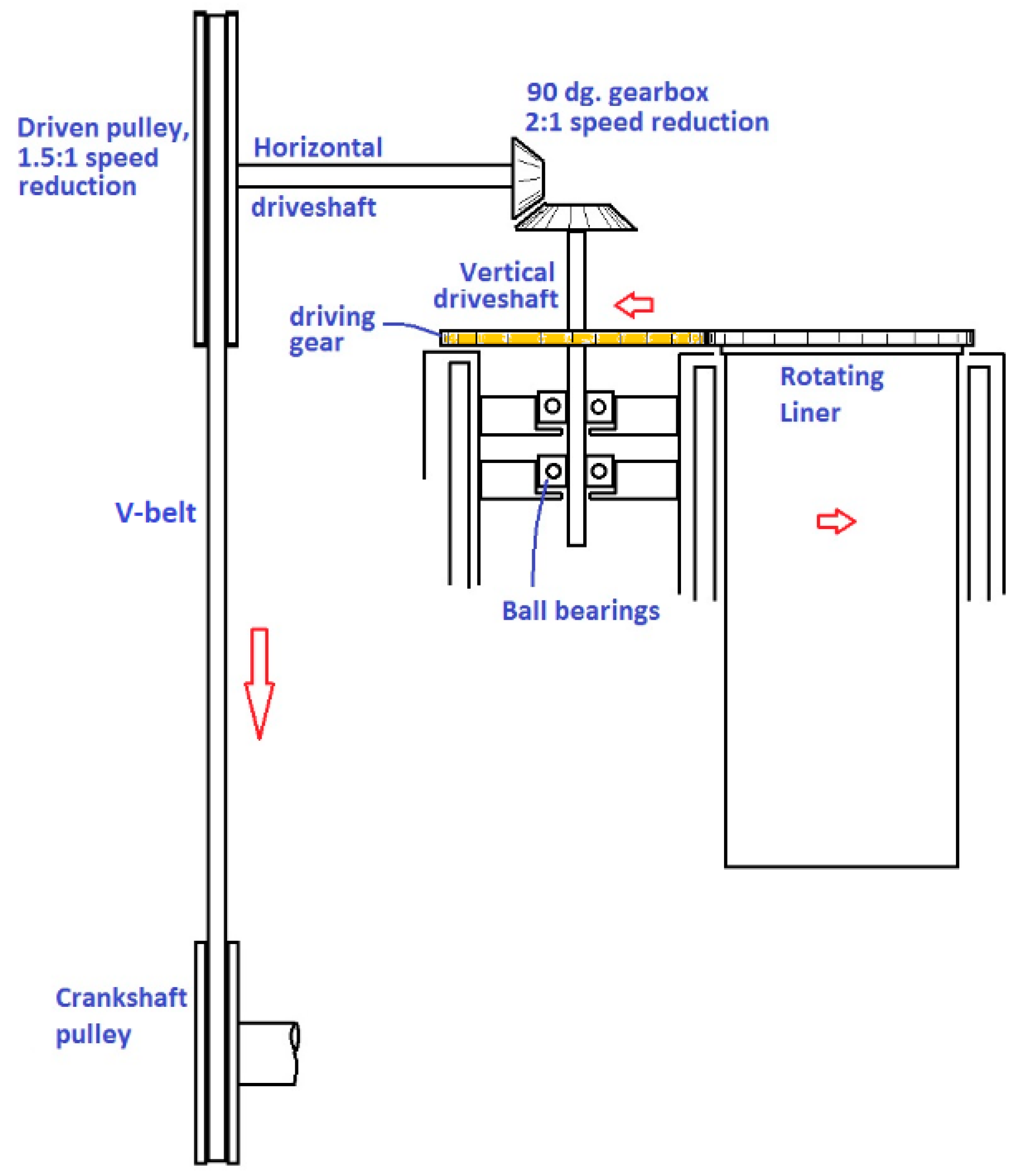
Figure 3.
Overall set up of the single cylinder RLE prototype. The V-belt that connects the two pulleys is not shown. The BSL is identical except for the rotating liner and driving mechanism.
Figure 3.
Overall set up of the single cylinder RLE prototype. The V-belt that connects the two pulleys is not shown. The BSL is identical except for the rotating liner and driving mechanism.
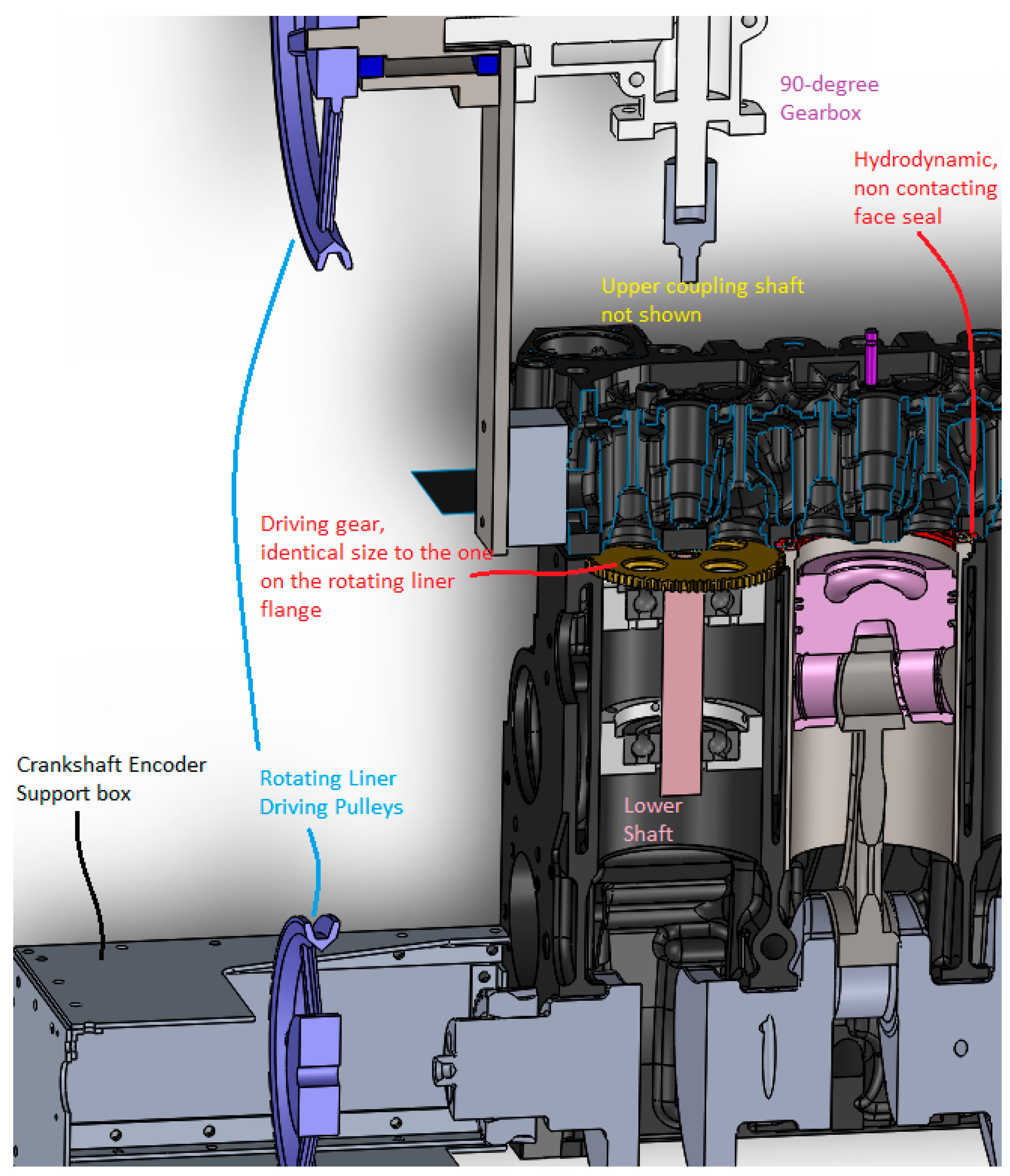
Figure 4.
Photograph of the single cylinder RLE prototype as installed in the dynamometer.
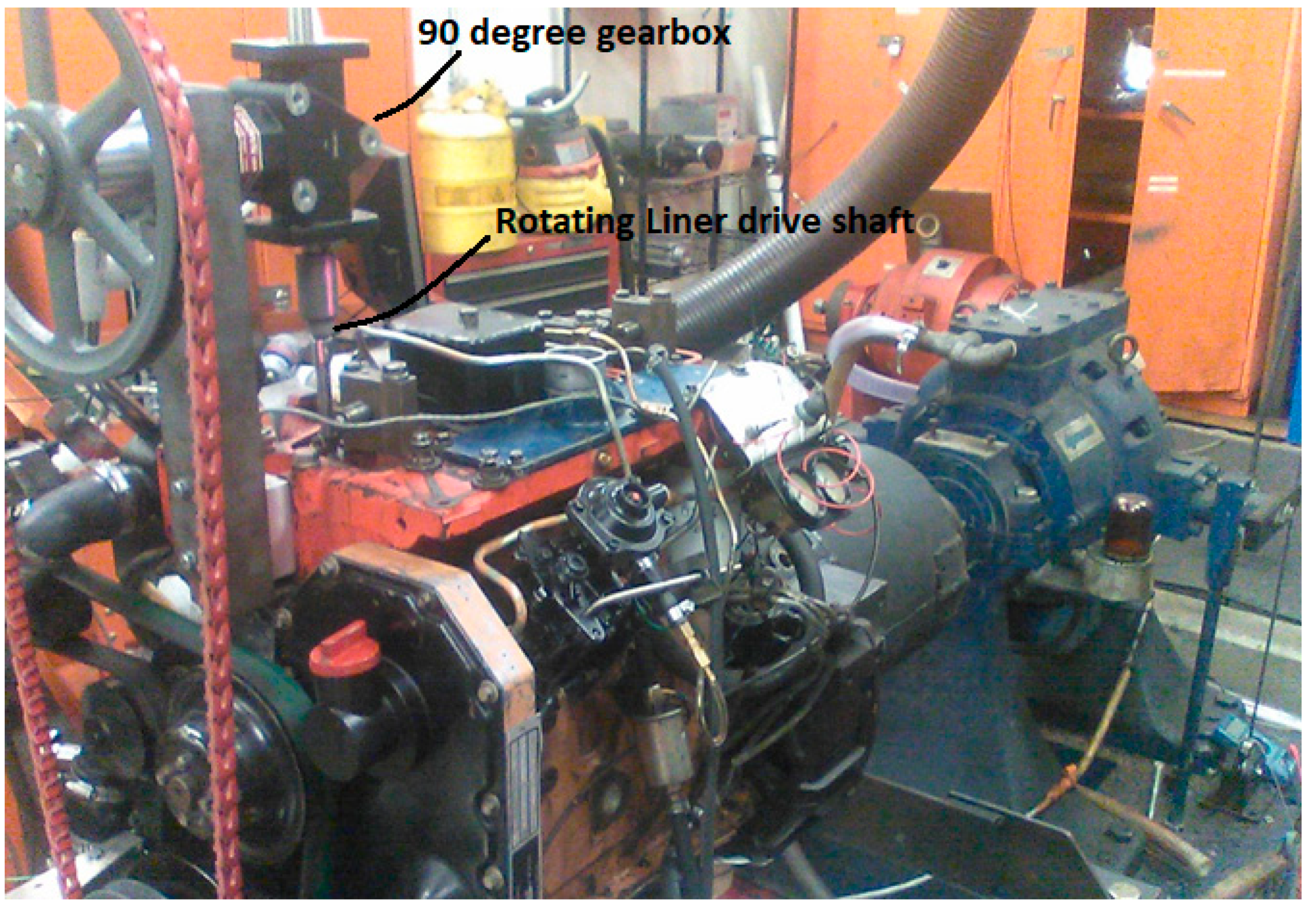
Figure 5.
Coolant circuit schematic.
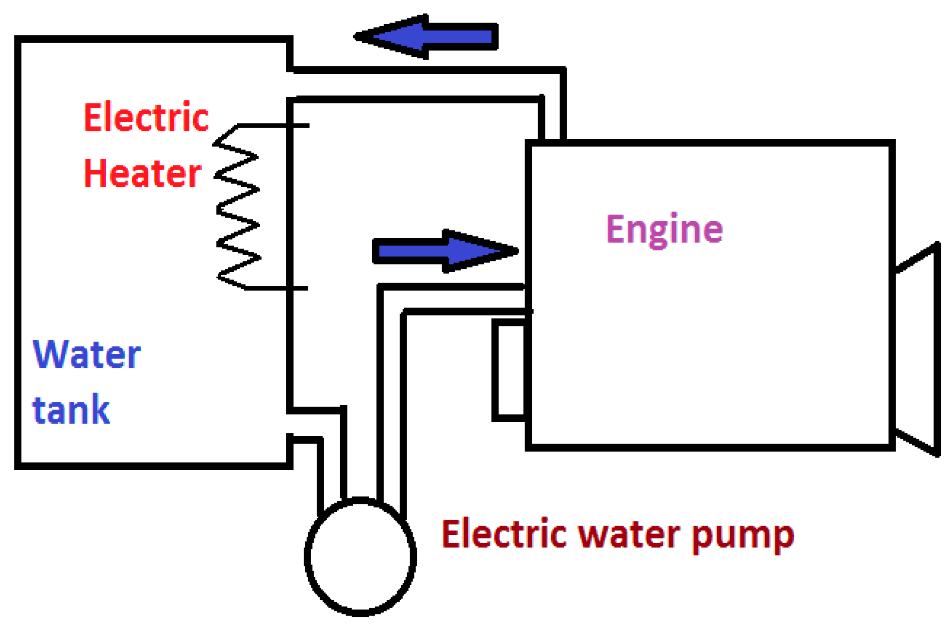
Figure 6.
Pressure trace and heat release for the BSL, operating at 8.5 bar IMEP and 1144 rpm, adiabatic heat release is 1615 J/cycle.
Figure 6.
Pressure trace and heat release for the BSL, operating at 8.5 bar IMEP and 1144 rpm, adiabatic heat release is 1615 J/cycle.
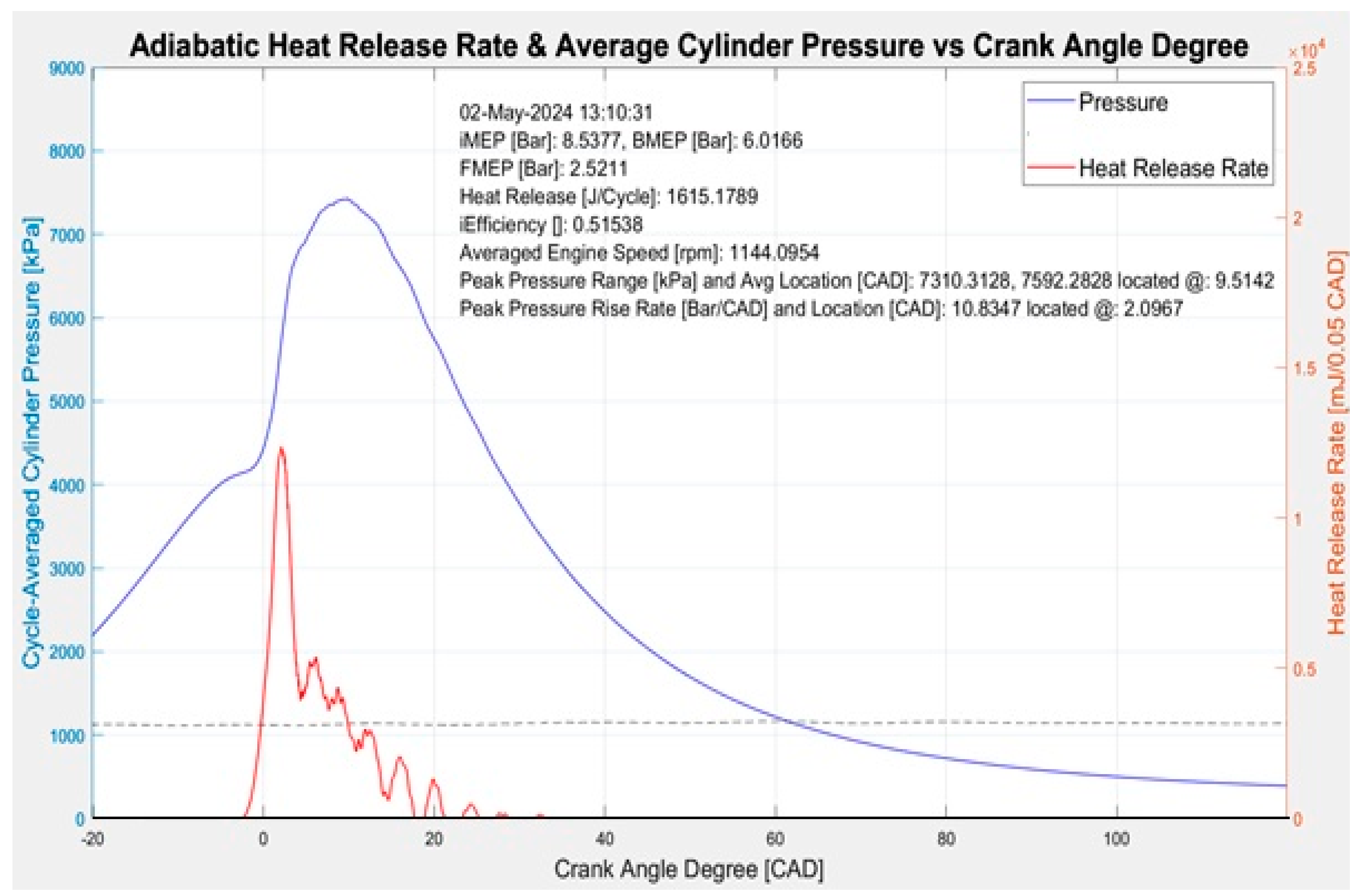
Figure 7.
Pressure trace and heat release for the RLE operating at 7.0 bar IMEP and 1132 rpm, injection timing more advanced than BSL with higher maximum rate of pressure rise. Adiabatic heat release is 1194 J/cycle. Note, heat release rate is plotted on a different scale than Figure 4 in order to show the negative portion of the heat release which corresponds to the fuel evaporation.
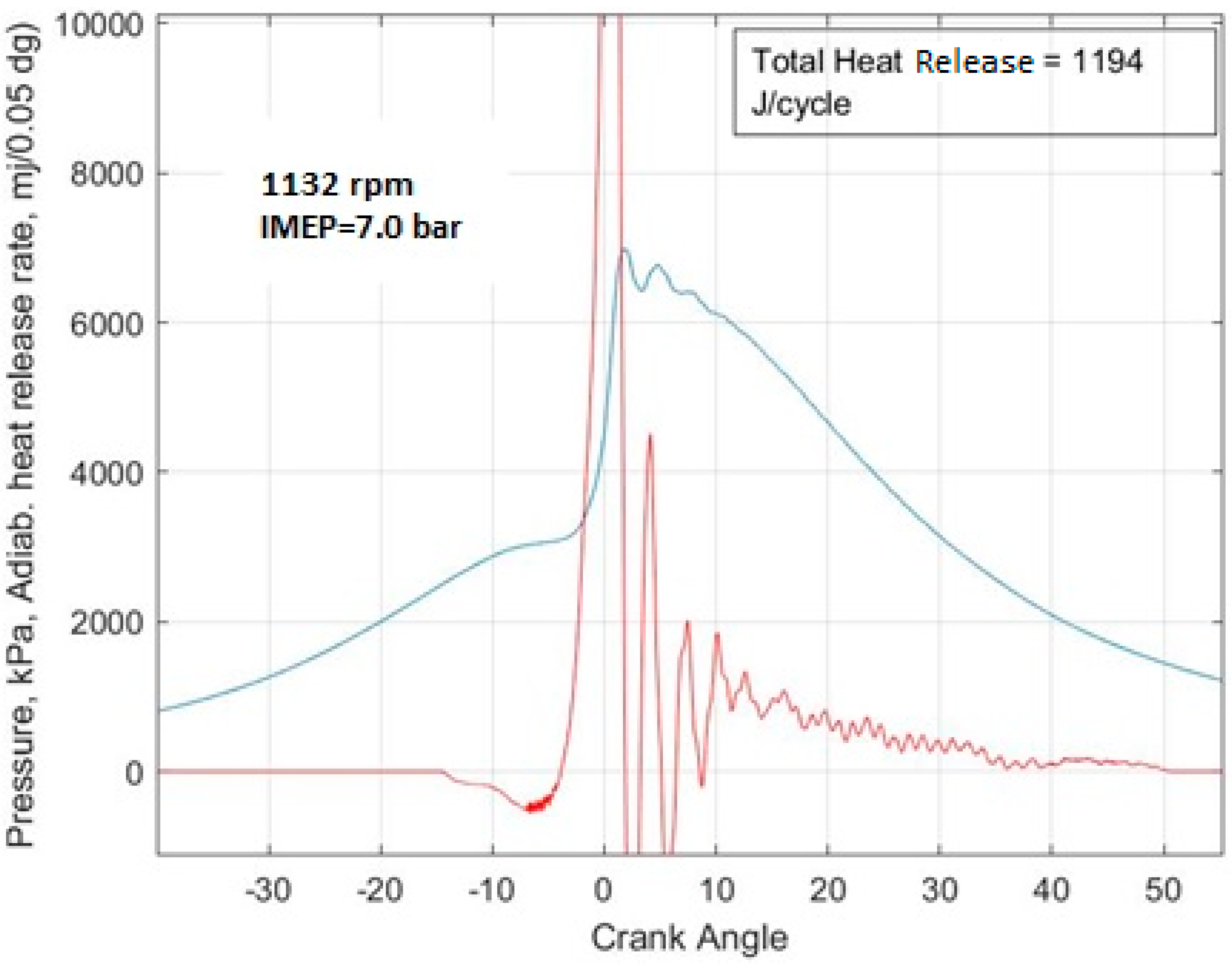
Figure 8.
BSL cylinder bore.
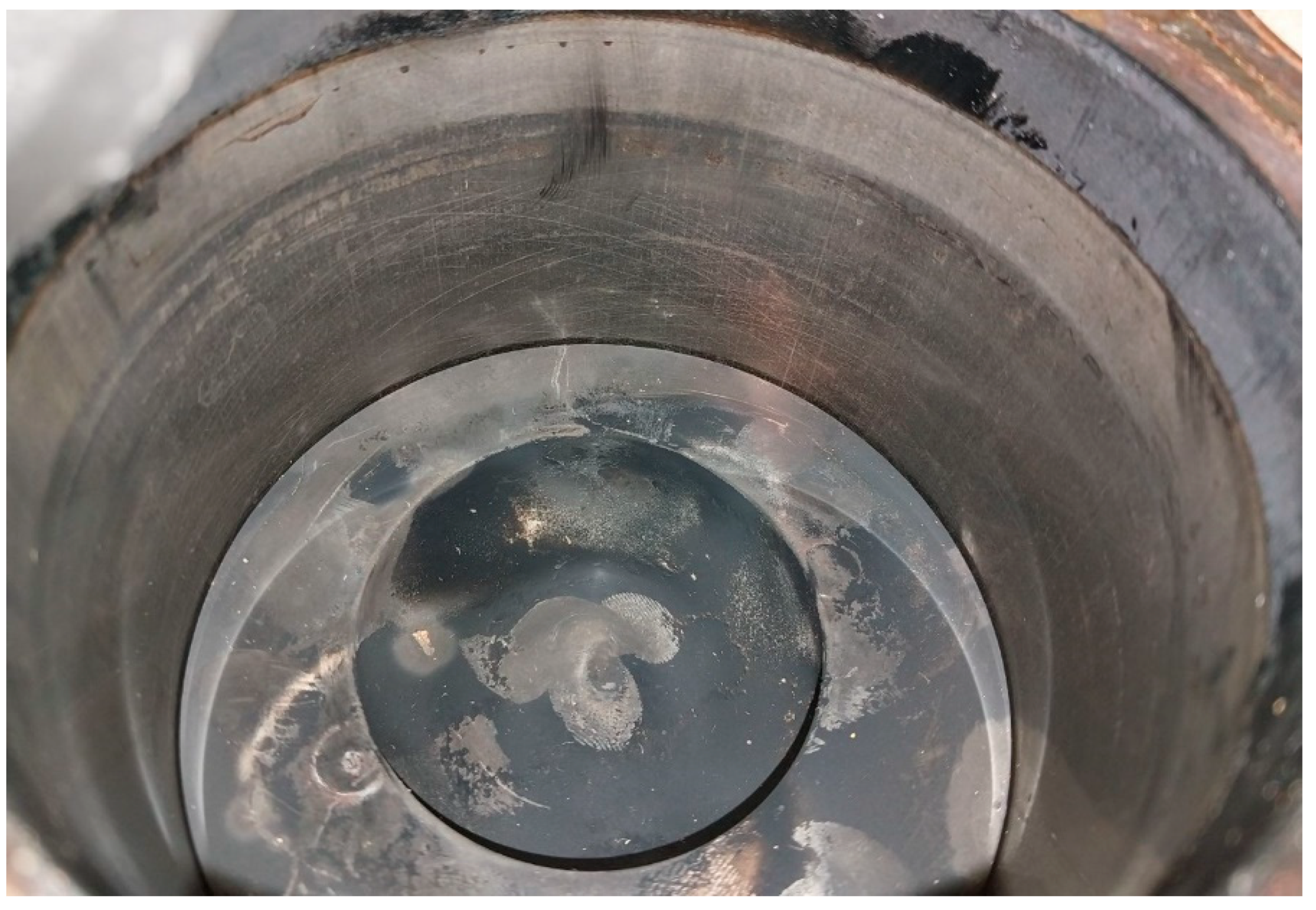
Figure 9.
FMEP response of the BSL with 15w40 oil, at about constant speed and increasing load. The superimposed effects of load (gas pressure), local heating, small variations in global heating (oil and coolant temperature), and engine speeds all generate changes in FMEP that offset each other. It is difficult to decompose these effects, but clearly the FMEP is not very sensitive on engine load as the increased gas load boundary friction due to increased gas load is partly compensated for by the reduced viscosity on the piston assembly caused by the local heating.
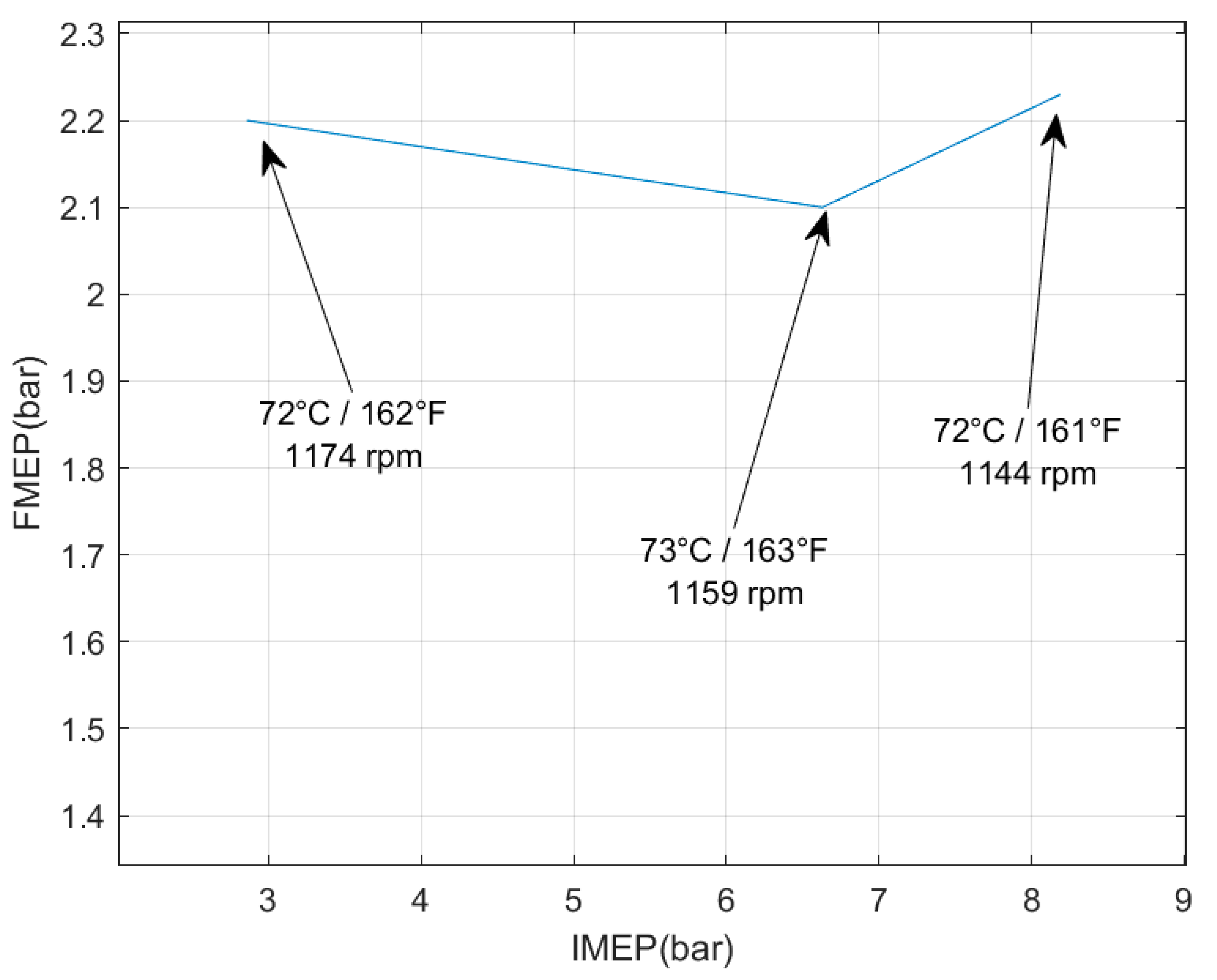
Figure 10.
Response of FMEP of the BSL engine with 10w30 oil at constant speed and increasing load. The oil temperature and speed are shown. The small variations in temperature and speed contribute to the small changes in FMEP along with the load. Overall the FMEP is not sensitive on load, as the increased gas load boundary friction is compensated for by the reduced viscosity on the piston assembly caused by the local heating.
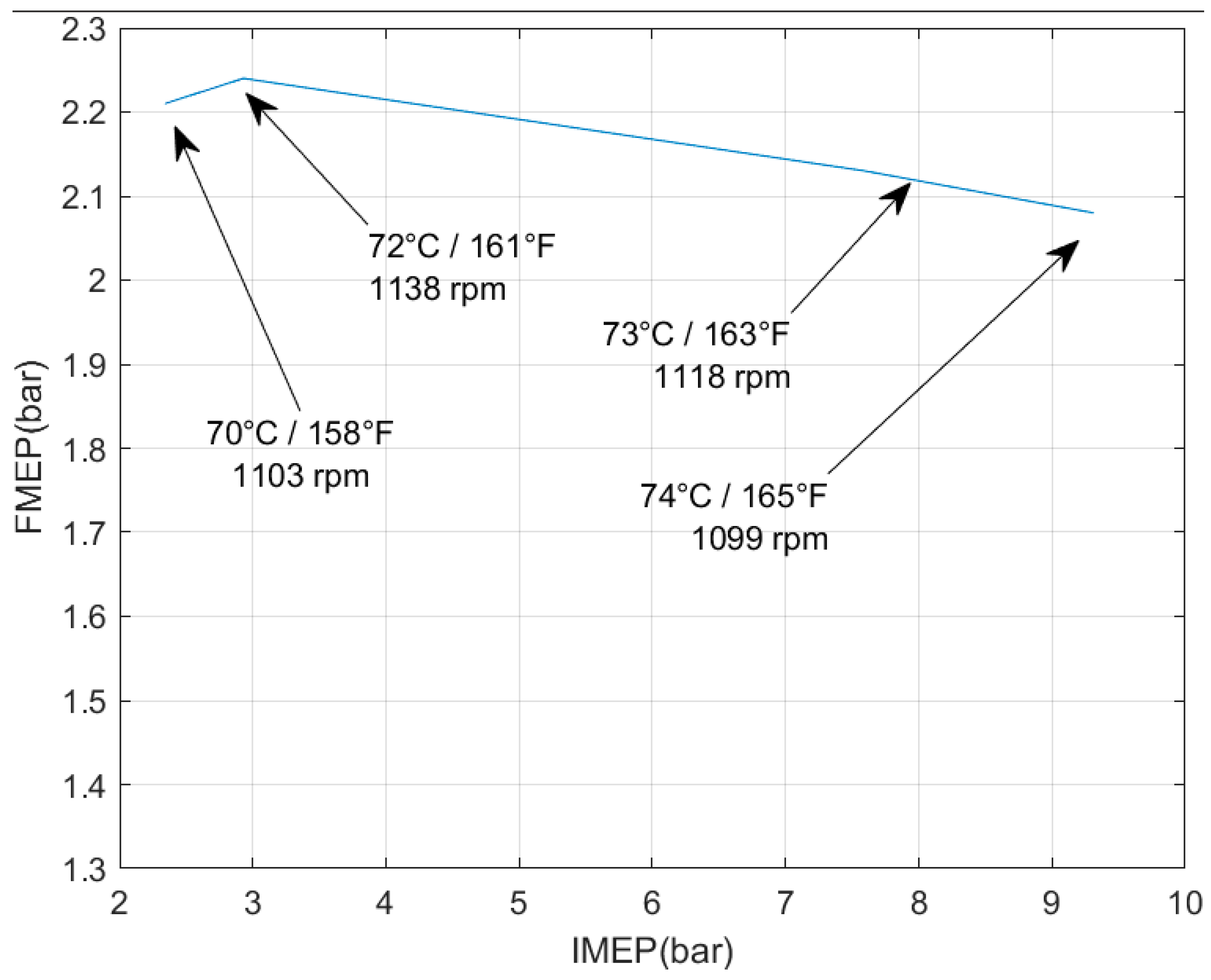
Figure 11.
RLE FMEP sensitivity to load at about constant speed (the RLE was run with 15w40 only for the tests in this paper). Effects of local and global warming and small speed variations are superimposed, but the IMEP (local heating) is the dominating factor.
Figure 11.
RLE FMEP sensitivity to load at about constant speed (the RLE was run with 15w40 only for the tests in this paper). Effects of local and global warming and small speed variations are superimposed, but the IMEP (local heating) is the dominating factor.

Figure 12.
The BSL and RLE shown in the same graph, all in the range of 1100 rpm and 70C (160F) oil temperature. Not only the RLE has much lower FMEP than the BSL, but the FMEP is more sensitive to local piston heating caused by increasing load.
Figure 12.
The BSL and RLE shown in the same graph, all in the range of 1100 rpm and 70C (160F) oil temperature. Not only the RLE has much lower FMEP than the BSL, but the FMEP is more sensitive to local piston heating caused by increasing load.
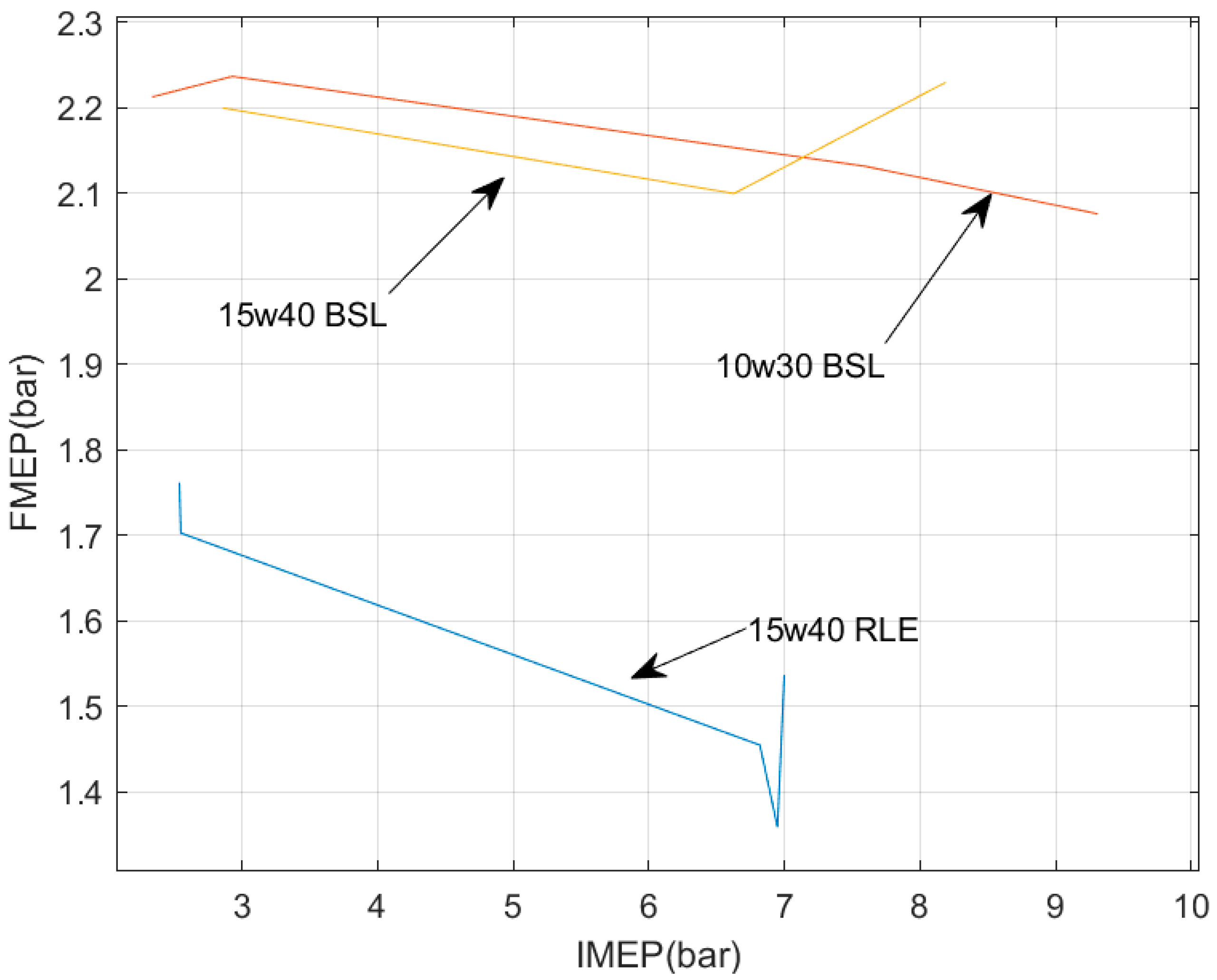
Figure 13.
Rotating liner removed for inspection. The areas of low clearance are shown (0.25 mm). The areas of large clearance, the two sections between the three journals, are expected to have increased heat transfer resistance by the oil film, causing a beneficial localized oil viscosity reduction.
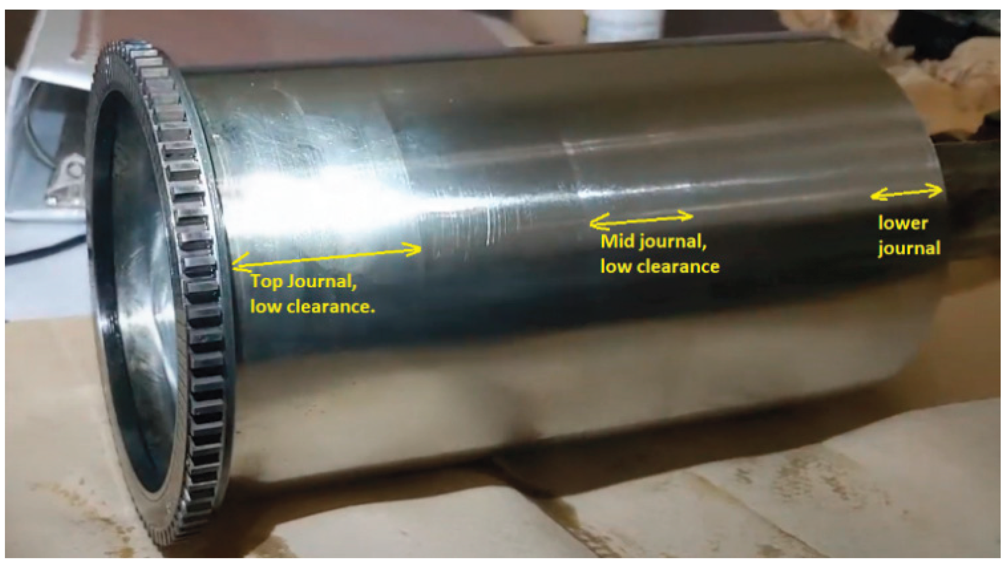

Table 1.
BSL FMEP at constant speed and increasing load, 15w40 lubricant.
| Engine Speed | IMEP | FMEP | Oil Temp | Coolant Temp |
| 1174 rpm | 2.86 bar | 2.20 bar | 72C (162F) | 70C (158F) |
| 1159 rpm | 6.63 bar | 2.10 bar | 73C (163 F) |
71C (159F) |
| 1144 rpm | 8.19 bar | 2.23 bar | 72C (161F) | 70C (158F) |
Table 2.
BSL FMEP at constant speed and increasing load, 10w30 lubricant.
| Engine Speed | IMEP | FMEP | Oil Temp | Coolant Temp |
| 1103 rpm | 2.34 bar | 2.21 bar | 70C (158F) | 70C (158F) |
| 1138 rpm | 2.93 bar | 2.24 bar | 72C (161 F) | 71C (160F) |
| 1118 rpm | 7.59 bar | 2.13 bar | 73C(163F) | 72C (161F) |
| 1099 rpm | 9.31 bar | 2.08 bar | 74C (165F) | 72C (162F) |
Table 3.
Examples of BSL FMEP performance with 15w40 oil at higher temperatures. .
| Engine Speed | IMEP | FMEP | Oil Temp | Coolant Temp |
| 1169 rpm | 5.61 bar | 2.12 bar | 78C (172F) | 72C (162F) |
| 1087 rpm | 9.12 bar | 2.06 bar | 79C (175 F) | 73C (163F) |
| 1160 rpm | 5.70 bar | 2.08 bar | 81C (177F) | 77C (170F) |
| 1127 rpm | 4.53 bar | 1.84 bar | 83C (182 F) | 84 C(178F) |
| 1105 rpm | 8.53 bar | 2.03 bar | 85C (184F) | 82 C (179F) |
Table 4.
RLE FMEP at constant speed and increasing load, 15w40 lubricant.
| Engine Speed | IMEP | FMEP | Oil Temp | Coolant Temp |
| 1065 rpm | 2.54 bar | 1.76 bar | 67C (153F) | 66C (150F) |
| 1076 rpm | 2.55 bar | 1.70 bar | 68C (155 F) | 66C (150F) |
| 1137 rpm | 6.82 bar | 1.46 bar | 70C(158F) | 68C (155F) |
| 1136 rpm | 6.95 bar | 1.36 bar | 72C (161F) | 69C (157F) |
| 1132 rpm | 7.00 bar | 1.54 bar | 69C (156F) | 68C (154F) |
Table 5.
RLE FMEP on a different day with various speeds and loads, 15w40 lubricant. The first test has highest global temperatures of all the RLE loaded tests, but also the highest speed. In terms of crank FMEP, the increased speed and reduced viscosity due to the temperature likely compensate each other, but the local piston heating dominates, even though the piston speed is about 15 % higher than the 1100 rpm tests. As for the idle case, it is not surprising that even a small increase in the global temperature produced a reduction in FMEP. .
| Engine Speed | IMEP | FMEP | Oil Temp | Coolant Temp |
| 1281 rpm | 6.45 bar | 1.27 bar | 74C (164F) | 73C (163F) |
| 832 rpm | 1.68 bar | 1.55 bar | 76C (169 F) | 74C (165F) |
Table 6.
Summary of all test results between the two engines loaded operation and around 1100 rpm.
| Engine Speed | IMEP | FMEP | Oil Temp | Coolant Temp |
| Baseline 15w40 lubricant | ||||
| 1174 rpm | 2.86 bar | 2.20 bar | 72C (162F) | 70C (158F) |
| 1159 rpm | 6.63 bar | 2.10 bar | 73C (163 F) | 71C (159F) |
| 1144 rpm | 8.19 bar | 2.23 bar | 72C (161F) | 70C (158F) |
| Baseline 10w30 lubricant | ||||
| 1103 rpm | 2.34 bar | 2.21 bar | 70C (158F) | 70C (158F) |
| 1138 rpm | 2.93 bar | 2.24 bar | 72C (161 F) | 71C (160F) |
| 1118 rpm | 7.59 bar | 2.13 bar | 73C(163F) | 72C (161F) |
| 1099 rpm | 9.31 bar | 2.08 bar | 74C (165F) | 72C (162F) |
| RLE 15w40 lubricant | ||||
| 1065 rpm | 2.54 bar | 1.76 bar | 67C (153F) | 66C (150F) |
| 1076 rpm | 2.55 bar | 1.70 bar | 68C (155 F) | 66C (150F) |
| 1137 rpm | 6.82 bar | 1.46 bar | 70C(158F) | 68C (155F) |
| 1136 rpm | 6.95 bar | 1.36 bar | 72C (161F) | 69C (157F) |
| 1132 rpm | 7.00 bar | 1.54 bar | 69C (156F) | 68C (154F) |
Table 7.
Approximate RLE fuel economy benefits in the field compared to the standard engines when both operate with 15w40 lube grade based on extrapolations from the test results. The main assumption is that the indicted thermal efficiency does not change between the two IMEP points since they are relatively close, and therefore the fuel consumption is proportional to the IMEP. .
| Speed | Load (BMEP) bar | Temp | BSL IMEP Mechanical efficiency |
RLE IMEP Mechanical efficiency |
RLE fuel consumption reduction |
| 800 rpm | 0 (idle) | 70C | 1.18 bar 0 % |
0.80 bar 0 % |
32.2% |
| 800 rpm | 0 (idle) | 90C | 1.14 bar 0 % |
0.76 bar 0 % |
33.3% |
| 1150-1400 rpm | 6.56 bar | 70-90C | 7.74 bar 84.7 % |
6.95 bar 94.3% |
10.1% |
Disclaimer/Publisher’s Note: The statements, opinions and data contained in all publications are solely those of the individual author(s) and contributor(s) and not of MDPI and/or the editor(s). MDPI and/or the editor(s) disclaim responsibility for any injury to people or property resulting from any ideas, methods, instructions or products referred to in the content. |
© 2025 by the authors. Licensee MDPI, Basel, Switzerland. This article is an open access article distributed under the terms and conditions of the Creative Commons Attribution (CC BY) license (http://creativecommons.org/licenses/by/4.0/).
Copyright: This open access article is published under a Creative Commons CC BY 4.0 license, which permit the free download, distribution, and reuse, provided that the author and preprint are cited in any reuse.


