

Submitted:
02 July 2025
Posted:
03 July 2025
You are already at the latest version
Abstract
In this study, a novel comparison between single phase 7-Level Packed U - Cell (PUC) and single phase 9-Level Cross Switches Cell (CSC) inverter with Model Predictive Controller (MPC) for solar grid-tied applications is presented. The efficacy of photovoltaic (PV) solar panels as a sustainable energy source is explored through the proposed inverter topology. Our innovation introduces a unique approach by integrating PV solar panels in PUC and CSC inverters in their two DC links rather than just one which increases power density of the system. The main benefit of both proposed models, other than the system’s power density, is their overall simplified design in comparison to other current topologies, thus both topologies offer enhanced power quality with reduced system complexity compared to traditional configurations. Moreover, the primary benefit of the used control topology for both designed models lies in its streamlined architecture, which eliminates the need for additional controllers such as PI controllers for grid reference current extraction. Furthermore, the implementation of Maximum Power Point Tracking (MPPT) technology directly optimizes power output from the PV panels, negating the necessity for a DC-DC booster converter during integration. To validate the proposed concept's performance for both inverters, extensive simulations were conducted using MATLAB/Simulink, assessing both inverters under steady-state conditions as well as various disturbances to evaluate its robustness and dynamic response. Both inverters exhibit robustness against variations in grid voltage, phase shift, and irradiation. By comparing both inverters, results demonstrate that the CSC inverter exhibits superior performance due to its booster feature which relies on generating voltage level greater than the DC input source. This primary advantage makes CSC a booster inverter.
Keywords:
Multilevel converters
; PUC inverter
; CSC inverter
; MPC
; MPPT
; Grid Connected PV applications
; Booster Inverter
1. Introduction
As world's energy demand keeps growing tremendously due to fossil fuels finite nature and their harmful emissions, the transition to clean energy won’t be just a decision or choice, but also a must and a necessity for building a sustainable energy future with a robust, resilient and equitable global ecosystem. Shifting to clean energy sources means integrating Renewable Energy sources such as solar and wind. Using Renewable Energy sources over all carbon emission sources contributes to climate changes mitigation, greenhouse emissions reduction, and finite natural resources conservation. This transition will absolutely resolve one of the most pressing issues facing the world.
Solar energy has become the fastest-growing renewable energy source globally due to its low maintenance requirements and lack of noise emissions, among other benefits. Worldwide, the annual demand for photovoltaic (PV) systems, solar energy system, is on the rise, with approximately 522 GW of new PV installations anticipated between 2019 and 2022 [1]. However, connecting PV systems to power grids presents several challenges, including choosing the appropriate grid node voltage level based on the capacity of the PV system, ensuring power quality management, and developing effective control systems [1,2].
Due to the urgent need for energy alternative transition and since inverters are tasked with converting the DC power generated by Renewable Energy systems into AC power that can be fed into the grid, researchers are focusing more on efficient power electronics inverters for energy conversion for high power applications. Therefore, improvement of power electronics inverters will facilitate renewable energy sources to integrate into the grid, and consequently helping in supplying high power loads to wide range of consumers.
Inverters can be categorized into two main families: 2-Level Inverters and Multilevel Inverters (MLIs). 2-Level inverters are characterized by their high switching frequency and low voltage amplitude accompanied with high harmonic contents which calls for big inductance for filtering it out [3]. These characteristics limit the use of 2-Level Inverters in medium-voltage-high-power applications [4]. To overcome these obstacles, MLIs are introduced to be integrated in power conversion stage. MLIs were first introduced by Baker and Lawrence in 1975 [5]. MLI minimizes voltage distortion leading to better power quality, decreases harmonic distortion allowing for a smaller filter size, decreases stress on switching devices, lowers detrimental effects, decreases switching losses, lowers electromagnetic interference and supports higher power ratings (increases voltage amplitude) [6].
MLIs are made up of advanced power semiconductors and DC voltage source(s) which generate an alternating output of distinct voltage levels from lower DC voltage levels. The output step voltage level is produced by the inverter between its output terminal and neutral reference node. The number of these output step voltage levels defines the inverter’s level number; for example if the inverter generates three distinct voltage levels then it is called three-level inverter and if it generates five distinct voltage levels then it is called five-level inverter . Thus, at least three voltage levels should be generated by the inverter, in each phase, in order to be classified as MLI. Although, higher number of voltage levels improves the output waveform's voltage and current quality (resulting in more sinusoidal, smoother waveforms with reduced total harmonic distortion), it also results in more complex and expensive system. Consequently, indicating the suitable number of an inverter’s voltage levels relies on cost, size, and its intended use [7]. As a result, MLIs continue to outperform conventional 2-level inverters by overcoming their shortcomings and drawbacks [8,9,10].
MLIs represent an appealing advancement for medium to high voltage and high-power applications, including high-power AC motor drives, active power filters, aerospace applications [11] ventilation applications [12], hybrid electric vehicles [13], and the integration of renewable energy sources into the grid [14].
Contemporary research on voltage source MLIs mainly categorizes them into three conventional types. Cascaded H-Bridge (CHB) was introduced in 1975 by grouping single-phase inverters in series [5,15], followed by the Neutral Point Diode Clamped (NPC) inverter which was introduced in 1981 [16], and the Flying Capacitor Inverter (FCI) [8]. With advancements in power electronics, several MLIs have been introduced and developed, including the Active Front-End Rectifier (AFE Rectifier), Matrix Converters, Packed U-Cell (PUC) [17,18], and Packed E-Cell (PEC) [19].
The CHB inverter, which requires multiple separate DC sources, is utilized in high-power applications, while the NPC inverter, using a single separate DC source, like the FCI, is suitable for medium and high-power applications. CHB and NPC are primarily utilized in motor drives. The FCI is particularly proposed for medium voltage applications. AFE rectifiers are employed in AC-DC power conversion, offering advantages over diode rectifiers in terms of sinusoidal input currents, bidirectional power flow capability, and controllable power factor. The Matrix Converter serves as an alternative to back-to-back configurations and is preferred in applications where size and volume are critical considerations.
In comparison to the aforementioned MLI topologies, PUC produces more voltage levels with superior power quality while utilizing fewer DC sources, utilizing just a single DC source, and fewer passive and active components [20,21]. Thus, PUC inverter can generate up to seven output voltage levels using six switches, one DC source, and one DC capacitor. However, NPC and FCI require a significant number of clamping diodes and flying capacitors respectively to achieve a higher number of output voltage levels [22,23]. Besides, in NPC inverter, other factors, like load power factor, can cause imbalances in the DC capacitor voltages [24]. Modified CHB topologies have been also proposed to enhance output voltage quality and decrease circuit components’ number [25]. However, these modifications necessitate different values for the DC sources. Consequently, PUC inverter is regarded as the most reliable and dependable among the above-mentioned MLI that is more compact and cost-effective.
Recently, a Cross Switches Cell (CSC) inverter, which is a modified version of PUC topology, was introduced in [26]. By incorporating two crossover bidirectional switches into the PUC design, it can generate 9 voltage levels. Thus, its maximum output voltage level exceeds the DC source voltage letting CSC of having boost capability. As a result, the CSC inverter produces 9 voltage levels while requiring fewer DC sources, capacitors, and switches compared to the CHB (symmetric/asymmetric), FCI, NPC, and PUC MLIs [26,27]. This reduction in components and sources lowers manufacturing costs, making the CSC ideal for applications where minimizing the number of DC sources and components is essential.
Given that MLIs are composed of multiple internal power semiconductors, various well-established modulation techniques have been developed and proposed for their control over the past few decades. The most commonly suggested and used techniques include Pulse Width Modulation (PWM) [28,29] and Space Vector Modulation (SVM) [30]. Other modulation techniques such as Space Vector Control (SVC) and Selective Harmonic Elimination (SHE) have been also reported [31,32,33]. Moreover, several control methods have been presented in literature to control MLIs’ switches such as Hysteresis Control, Model Predictive Control (MPC),and Artificial Intelligence-Based Methods [34,35,36].
The MPC method has been successfully utilized across various MLI topologies discussed in the literature, including 3-level NPC, 4-level FCI, CHB MLIs, 7-level PUC, and matrix converters [37,38]. The FCS-MPC directly implements control actions on the inverter without needing a modulation process [37]. Additionally, FCS-MPC is a multi-objective control strategy that optimizes a specified cost function based on the application's requirements.
This paper presents a comparison between a single phase 7L-PUC grid-tied inverter and single phase 9L-CSC grid tied inverter, in which the contribution of this paper is demonstrated by replacing both the input battery source and DC link capacitor with solar panels (PV panels) in the two proposed inverters to increase the power density of the system, as illustrated in Figure 1(a) and Figure 2(a). Both proposed inverters undergo the same control topology in which both inverters utilize a Finite Set Model Predictive Controller (MPC), incorporating a Maximum Power Point Tracking (MPPT) technique to ensure maximum power output from the PV panels. The control topology proposed for both inverters is characterized by reduced complexity. The paper discusses the PUC converter in Section 2, followed by an elaboration on CSC inverter in Section 3. Section 4 provides an introduction to the MPC configuration for the grid-connected 7L-PUC inverter and 9L-CSC inverter. Then, section 5 presents simulation results for PUC inverter while section 6 presents simulation results for CSC inverter using MATLAB/Simulink for both inverters. Finally, Section 7 concludes the work through comparing both proposed topologies.
2. Packed U-Cell Converter Topology
The PUC converter was developed and introduced by Ounejjar and Al-Haddad [17,18]. It is an adapted version of the CHB, notable for having fewer switches while achieving a high number of output voltage levels. The PUC converter features six active switches and two DC links, as depicted in Figure 1(b). Operating in inverter mode, it utilizes an isolated DC source as the primary DC link and a capacitor as a secondary, auxiliary DC link. The voltage of the capacitor is regulated based on the DC source voltage. The switches are considered ideal, operating in only two states: ON or OFF. They function in complementary pairs, with Sa paired with Sd, Sb with Se, and Sc with Sf. As illustrated in Figure 1(b), each complementary pair connects to a DC link, forming a U-cell configuration. The PUC setup generates eight switching states, as detailed in Table 1, with each state creating a specific current path through the circuit, involving the DC sources and the load. The number of output voltage levels varies based on the voltage ratio between the DC links.
3. Crossover Switches Cell Converter Topology
Single phase 9-level grid tied CSC inverter is depicted in Figure 2(b). This CSC system includes one DC source and one capacitor, with their voltage levels designated as V1 and V2, respectively. The system comprises eight switches, labeled S1 to S8, among which S2 and S5 only function as bidirectional switches. The switches S1 and S4, as well as S3 and S6, are operated in a complementary manner, while one switch only from the group (S2, S5, S7, S8) is activated ON at any given time. The CSC setup generates sixteen switching states, as detailed in Table 5.
Adding two crossover switches (S7 and S8) between DC link and capacitor to the PUC inverter results in two extra output voltage levels of ±(V1 + V2). This adjustment also enhances the stability of the DC voltage by creating additional paths for the charging and discharging of the capacitor [26,44]. Thus, to achieve a 9-level output voltage, the capacitor voltage V2 must be regulated to V1/3.
It is important to mention that the novelty here is also to modify the CSC topology by replacing both the input battery source and DC link capacitor with PV panels as shown in Figure 2 (a). Thus, PV solar panels are connected in parallel with a capacitor replacing the DC battery input and also PV solar panels are connected in parallel with a capacitor in the second DC link as well. Therefore, the considered circuit for our study in this section is the one illustrated in Figure 2(a).
4. Model Predictive Control Design
This paper employs MPC to manage PUC and CSC inverters, utilizing its ability to forecast the future behavior of variables [39,40]. MPC controller is distinguished from traditional controllers due to its flexibility in managing and controlling various variables with constraints. This approach eliminates the need for a cascaded control structure for controlling system’s parameters. Thus, MPC features two loops in its control architecture: a fast inner loop and a slower outer loop. In each switching state, the MPC assesses the controlled variable x(k) and predicts its future value x(k+1) using the predictive control. It then evaluates a cost function, in which the minimum cost function is selected by MPC. The switching state that corresponds to the selected cost function is regarded as the optimal switching state, which is consequently applied to the inverter through switching pulses.
4.1. Model Predictive Control Design for PUC
In [41,42], both load current and capacitor voltage V2 are controlled by the MPC. However, in this study, we focus on controlling load current, the output voltage of the PV in the primary DC link and the output voltage of the PV in the secondary auxiliary DC link. To simplify calculations, we introduce two new variables, S1 and S2, which are derived from Sa, Sb, and Sc, as indicated in equations (1) and (2).
By inserting (1) and (2) into the switching states of Table 1, we derive the simplified switching states presented in Table 6
PUC inverter produces voltage vector Vin that is generated using (3).
Load current dynamics is represented in (4) using vector differential equation:
Using Euler Forward Approximation, Load current can be expressed as shown in equation (5)
Replace (5) in (4) to derive (6)
Once the predicted load current is obtained, the cost function g is formulated as shown in equation (7).
As previously mentioned, the cost function g is calculated for each switching state, and the MPC selects the minimum cost function. Consequently, S1 and S2 are determined based on this minimum cost function, which then identifies the corresponding switching state number using Table 6. The switching states for Sa, Sb, and Sc are then selected from Table 1 to be implemented on the PUC inverter switches.
At instant k, the load current or grid current is measured, and based on these readings, is generated and predicted using equation (6). The cost function is then calculated at instant k using equation (7). in the cost function represents the grid reference current where represents the Vmppt of the PV in the primary DC link, represents output voltage of the PV in the primary DC link, represents Vmppt of the PV in the secondary auxiliary DC link, and represents the output voltage of the PV in the secondary auxiliary DC link.
Grid reference current depends on grid voltage, for which a PLL block is utilized to extract the phase angle, ensuring that the grid reference current is in phase with the grid voltage. To adjust the power factor between the grid voltage and the grid reference current, a phase shift is applied to the angle generated by the PLL block. If the phase shift is set to zero, the grid voltage and grid reference current are in phase, achieving unity power factor operation. Otherwise, reactive power will be exchanged with the grid.
Regarding the amplitude of the grid reference current, if PUC operates in its standard configuration, as shown in Figure 1(b), the amplitude is chosen arbitrarily to match the required power to be injected into the grid. In this study, however, PUC topology is modified as depicted in Figure 1(a), with PV solar panels connected in parallel with a capacitor replacing the DC battery input. Additionally, solar panels are connected in parallel with a capacitor in the second DC link. This modification necessitates deriving the amplitude of the grid reference current from the PV solar power or using a PI controller to minimize the voltage differences between the reference and actual DC link [43]. In our proposed control strategy, the grid reference current amplitude is generated from the PV solar power, calculated by dividing the PV solar power by Vs.
It is essential to highlight that the cost function in equation (7) should ideally include weighting factors if there are more than one variable parameter to control. Weighting factors are typically used to mitigate coupling effects between multiple controlled variables in the cost function. Accordingly, weighting factors in this study are chosen as follows; L= 10, D1=5 and D2=5.
Figure 3 illustrates the flow chart of the proposed MPC topology applied to the single phase 7-level PUC inverter. As noted, MPC consists of two loops: an inner loop and an outer loop. The outer loop measures the grid current at instant k, , at each sampling time. Meanwhile, for each possible state, the inner loop calculates the predictive grid current value and generates the corresponding cost function to store the optimal values. The inner loop is executed eight times to account for the eight possible switching states in the PUC. After completing the executions for eight possible states, the minimum cost function value is selected, and its related switching state is applied to the PUC’s six switches.
To incorporate PV solar applications in our work, an MPPT algorithm is necessary to enhance PV efficiency, achieve accurate and rapid tracking performance, and reduce oscillations around the MPP. MPPT methods can be categorized as on-line or off-line. The on-line method regulates the PV voltage at the MPP voltage, while the off-line method is based on models techniques. Perturbation and Observation (P&O) is a common on-line method and is widely used among MPPT techniques due to its simplicity. P&O technique is implemented in our work, and its detailed operational method is described in [42]. The P&O technique directly manages and controls the power output, in which the need for a DC-DC boost converter will be eliminated when integrating PV solar panels with the PUC inverter.
The complete system model demonstrating MPC applied on the single-phase 7L-PUC inverter is illustrated in Figure 4.
4.2. Model Predictive Control Design for CSC
By applying Kirchhoff’s laws, DC source voltage V1(t), capacitor voltage V2(t), grid current is(t), grid voltage Vs(t), output voltage Vin(t), and the eight switches Si {i=1…8} can be formulated as follows:
Capacitor voltage is represented in (8)
Using Euler Forward Approximation, Voltage capacitor can be expressed as shown in equation (9)
Compare (8) and (9) to derive (10)
CSC inverter produces voltage vector Vin that is generated using (11).
Load current dynamics is represented in (12) using vector differential equation:
Using Euler Forward Approximation, Load current can be expressed as shown in equation (13)
Replace (13) in (12) to derive (14)
Once the predicted load current is obtained, the cost function g is formulated as shown in equation (15).
As previously mentioned, the cost function g is calculated for each switching state and the MPC selects the minimum cost function. Consequently, S1, S2, S3, S4, S5, S6, S7, and S8 are determined based on this minimum cost function.
The same control strategy that is applied for PUC inverter is also applied for CSC inverter in which at instant k, the load current or grid current is measured, and based on these readings, is generated and predicted using equation (14). Cost function is then calculated at instant k using equation (15). in (15) represents the grid reference current where represents the Vmppt of the PV in the primary DC link, represents output voltage of the PV in the primary DC link, represents Vmppt of the PV in the secondary auxiliary DC link, and represents the output voltage of the PV in the secondary auxiliary DC link.
As for Grid Reference Current, a PLL block is utilized to extract the phase angle from the grid voltage, ensuring that the grid reference current is in phase with the grid voltage. To adjust the power factor between the grid voltage and the grid reference current, a phase shift is applied to the angle generated by the PLL block.
Regarding the amplitude of the grid reference current, it is derived from the PV solar power, calculated by dividing the PV solar power by Vs.
As for the weighting factors, they are also chosen as follows; L= 10, D1=5 and D2=5.
Figure 5 illustrates the flow chart of the proposed MPC topology applied to the single phase 9-level CSC inverter. As mentioned previously, MPC consists of two loops: an inner loop and an outer loop. The outer loop measures the grid current at instant k, , at each sampling time. Meanwhile, for each possible state, the inner loop calculates the predictive grid current value and generates the corresponding cost function to store the optimal values. The inner loop is executed sixteen times to account for the sixteen possible switching states in the CSC. After completing the executions for sixteen possible states, the minimum cost function value is selected, and its related switching state is applied to the CSC’s eight switches.
MPPT algorithm is necessary to be applied in the control strategy due to the PV solar incorporation in our work. P&O technique is also implemented here. P&O technique directly manages and controls the power output, in which the need for a DC-DC boost converter will be eliminated when integrating PV solar panels with the PUC inverter.
The complete system model demonstrating MPC applied on the single-phase 9L-CSC inverter is illustrated in Figure 4.
5. Simulation Results and Analysis for PUC
To assess the effectiveness and reliability of our proposed approach, we conducted simulations of the entire system using MATLAB/Simulink. The sampling time was configured to Ts = 20μs. Irradiance and temperature were set at 1000 W/m2 and 25˚C, respectively. Table 7 displays the parameters of the system utilized in the simulations.
Figure 6 and Figure 7 display the results during steady-state operation. Figure 6 shows the inverter’s 7-level output voltage (Vin). Figure 7 confirms that the inverter’s output current (is) and grid voltage (Vs) remain in phase during steady-state operation. Also, it illustrates that the current (is) consistently tracks the grid reference current (). Additionally, a harmonic distortion level (THD) of about 2.8% has been achieved, demonstrating that the injected current aligns well with grid connectivity standards and requirements, which specify a limit of less than 5%.
Figure 8 and Figure 9 present the voltage and current waveforms during changes in grid voltage. Grid voltage was modified from 300V to 270V (phase-to-phase Vrms) to 270V (phase-to-phase Vrms), reflecting a 10% change in grid voltage. It is clear from Figure 8 that these changes do not affect the inverter’s voltage. Figure 9 indicates that the grid current continues to meet the desired values, even though the grid voltage experiences a slight drop. It also demonstrates that the current (is) continues to track the grid reference current () despite disturbances caused by variations in grid voltage. Furthermore, a harmonic distortion level of roughly 2.6% has been obtained, confirming that the injected current adheres to the grid connectivity standards and requirements.
To further evaluate the system's robustness, an additional test was conducted aimed at exchanging reactive power with the grid. This resulted in a sudden shift in the phase angle between the grid voltage and current from 0° to 30°, altering the power factor (PF) from 1 to 0.85. Figure 10 and Figure 11 illustrate the simulation results of this change. As shown in Figure 10, the inverter's voltage remains unaffected. Figure 11 demonstrates that the grid voltage and current are initially in phase but later exhibit a phase shift of π/6 when the delay is adjusted, indicating the generation of reactive power. It also reveals that the current (is) continues to track the grid reference current () during the reactive power variation disturbance. It has also been confirmed that the injected current satisfies the grid connectivity norms and regulations, with a THD level of around 2.6%.
A test on irradiation variation was also conducted on the proposed system. This involved a sudden change in irradiation levels, ranging from 500 W/m² to 1000 W/m². Figure 12, Figure 13, Figure 14, Figure 15 and Figure 16 illustrate the simulation results of this operation. As shown in Figure 12, the inverter's voltage remains unaffected during the irradiation variation. Figure 13 indicates that while the grid current values fluctuate slightly, the grid voltage remains constant. It also demonstrates that the current (is) continues to track the grid reference current () during the disturbance caused by the irradiation variation. Figure 14 confirms the increase in power output from the PV solar panels as irradiation levels rise. Figure 15 demonstrates the well tracking voltages of VDC1 and Vmppt(DC1) during irradiation variation. Whereas, Figure 16 illustrates the well balanced and tracked voltages of VDC2 and Vmppt(DC2) Moreover, THD level varies from 5.3% to 3.4%.
6. Simulation Results and Analysis For CSC
To evaluate the effectiveness and reliability of our proposed method, we did for the CSC topology the same procedure as we did for PUC topology, thus we performed simulations of the entire system using MATLAB/Simulink, with a sampling time set to Ts = 20μs. Irradiance and temperature were set at 1000 W/m2 and 25˚ C, respectively. The parameters used in the simulations are shown in Table 8.
Figure 17 and Figure 18 present the results observed during steady-state operation of the CSC inverter. Figure 17 illustrates the inverter’s 9-level output voltage (Vin). Figure 18 confirms that the inverter’s output current (is) and grid voltage (Vs) remain in phase during steady-state conditions. It also shows that the current (is) consistently follows the grid reference current (). It is important to mention that a harmonic distortion level of about 3% has been achieved, indicating that the injected current satisfies the grid connectivity criteria and standards, which call for a threshold of less than 5%.
Figure 19 and Figure 20 display the voltage and current waveforms during variations in grid voltage. The grid voltage was adjusted from 300V (phase-to-phase Vrms) to 270V (phase-to-phase Vrms), representing a 10% change. As seen in Figure 19, these adjustments do not impact the inverter’s 9-level output voltage. Figure 20 shows that the grid current continues to meet the target values, even though the grid voltage experiences a slight decrease. It also indicates that the current (is) remains aligned with the grid reference current () despite the disturbances caused by changes in grid voltage. Furthermore, THD level of approximately 2.7% has been reached.
To further assess the system's robustness, an additional test was performed to facilitate the exchange of reactive power with the grid. This led to a sudden change in the phase angle between the grid voltage and current from 0° to 30°, which modified the power factor (PF) from 1 to 0.85. Figure 21 and Figure 22 depict the simulation results of this adjustment. As indicated in Figure 21, the inverter's voltage remains stable. Figure 22 shows that while the grid voltage and current start off in phase, they later display a phase shift of π/6 when the delay is modified, signifying the generation of reactive power. It also demonstrates that the current (is) continues to follow the grid reference current () during the disturbance caused by the variation in reactive power. Additionally, a THD level of about 2.94% has been attained.
A test was also performed on the proposed system to assess irradiation variation, which involved a sudden change in irradiation levels from 500 W/m² to 1000 W/m². Figure 23, Figure 24, Figure 25, Figure 26 and Figure 27 present the simulation results of this experiment. As depicted in Figure 23, the inverter's voltage remains unchanged during the irradiation variation. Figure 24 shows that while the grid current values experience slight fluctuations, the grid voltage stays constant. It also illustrates that the current (is) continues to follow the grid reference current () despite the disturbances caused by the changes in irradiation. Figure 25 assures an increase in power output from the PV solar panels corresponding to the rise in irradiation levels. Figure 26 demonstrates the well tracking voltages of VDC1 and Vmppt(DC1) during irradiation variation. Whereas, Figure 27 illustrates the well balanced and tracked voltages of VDC2 and Vmppt(DC2) Moreover, THD level varies from 5.2% to 3.7%.
7. Conclusion
In conclusion, the transition to renewable energy sources is imperative for addressing global energy demands and mitigating climate change. In this study, we explored the advancements in MLIs with a specific focus on the PUC inverter and the newly introduced CSC inverter. Both inverters serve the critical function of converting DC power from renewable energy sources into AC power for grid integration.
This paper is contribution for [45] in which it provides a detailed comparison between a new design for the 7-Level PUC inverter and the 9-Level CSC inverter for solar grid-tied application, both utilizing a MPC as a control strategy with Maximum Power Point Tracking (MPPT). The novelty of this paper is represented in integrating PV solar panels in both PUC inverter and CSC inverter in their two DC links and not only in one DC link like the one discussed in [42] and [44]. This novelty will increase the power density of the system.
The PUC inverter, with its configuration of six active switches and ability to generate up to seven distinct output voltage levels, offers a compact solution that minimizes component count while maintaining high power quality and minimizes harmonic distortion while maintaining cost-effectiveness. It effectively balances the trade-offs between performance and complexity, making it suitable for a variety of medium to high-power applications.
On the other hand, the CSC inverter represents a significant leap forward, functioning as a booster inverter that not only generates nine output voltage levels but also offers voltage levels greater (equals to 4E) than the DC input (V1= 3E). This boost capability, achieved through the integration of two crossover bidirectional switches to PUC inverter design, allows for flexibility and efficiency in various applications while reducing the number of required DC sources and components. This enhancement not only improves output voltage quality but also reduces manufacturing cost and complexity, positioning the CSC inverter as an attractive option for applications where minimizing system complexity and costs is essential.
The design solely relies on the MPC to control both inverters, PUC and CSC, eliminating the need for additional controllers such as PI controllers to extract grid reference current. Also, the applied strategy eliminates the need for a separate DC-DC booster converter while integrating PV solar panels to PUC and CSC inverters since the used P&O technique is directly employed to manage power delivery, ensuring efficient operation without added complexity.
Both inverters were subjected to simulations using MATLAB/Simulink to validate their performance, demonstrating robustness under various conditions, including steady state, grid voltage fluctuations, phase shift variation and changes in solar irradiation. The results confirm that the proposed designs maintain stability and efficiency, making them suitable for future integration of renewable energy sources into the grid.
Overall, while both inverter topologies provide significant advantages for renewable energy integration, the CSC inverter stands out for its superior output boosting capability and reduced component requirements as provided in Table 9. This comparison highlights the ongoing innovation within power electronics, underscoring the importance of selecting appropriate inverter technologies to facilitate a sustainable and resilient energy future. As the world moves toward cleaner energy solutions, these advancements will play a crucial role in ensuring efficient energy conversion and maximizing the utilization of renewable resources.
Author Contributions
Conceptualization, R.H., F.S.,K.H and H.K.; methodology, R.H., F.S.,K.H and H.K.; validation R.H., F.S.,K.H and H.K.; formal analysis, R.H., F.S.,K.H and H.K.; investigation, R.H.; resources, R.H.; data curation, R.H.; writing—original draft preparation, R.H.; writing—review and editing, R.H; visualization, R.H.; supervision, R.H., F.S.,K.H and H.K.; project administration, F.S.,K.H and H.K.. All authors have read and agreed to the published version of the manuscript.
Funding
This research received no external funding.
Data Availability Statement
The raw data supporting the conclusions of this article will be made available by the authors on request.
Acknowledgments
This work has been supported by the Saint-Joseph University of Beirut joint grant program.
Conflicts of Interest
The authors declare no conflicts of interest.
References
- Feldman, D.J.; Zwerling, M.; Margolis, R.M. Q2/Q3 2019 Solar Industry Update. National Renewable Energy Laboratory (NREL), Colorado, USA, November 12, 2019; https://doi.org/10.2172/1578269.
- Lu, C.; Guan, S.; Yan, M.; Zhang, F.; Wu, K.; Wang, B. Grid Connected Photovoltaic Power Generation Station and it's Influence on Dispatching Operation Mode. 2018 2nd IEEE Conference on Energy Internet and Energy System Integration (EI2), Beijing, 2018; pp. 1-4. https://doi.org/10.1109/ei2.2018.8581917.
- Gupta, K.K.; Jain, S. A Novel Multilevel Inverter Based on Switched DC Sources. IEEE Transactions on Industrial Electronics, July 2014; Vol. 61 No. 7, https://doi.org/10.1109/tie.2013.2282606.
- Vadizadeh, H.; Farokhniah, N.; Toodeji, H.; Kavousi, A. Formulation of line-to-line voltage total harmonic distortion of two-level inverter with low switching frequency. IET Power Electronics 2013, vol. 6 no. 3, pp. 561-571.
- Baker, R.H.; Bannister, L.H. Electric Power Converter. US. Patent Number 3,867,643, 1975.
- Hariri, R.; Sebaaly, F.; Kanaan, H.Y. A Review on Modulated Multilevel Converters in Electric Vehicles. Proc. IECON’20, Singapore, Oct. 18-21; 2020, pp. 4987–4993.
- Qashqai, P.; Sheikholeslami, A.; Vahedi, H.; Al-Haddad, K. A Review on Multilevel Converter Topologies for Electric Transportation Applications. 2015 IEEE Vehicle Power and Propulsion Conference (VPPC), https://doi.org/10.1109/vppc.2015.7352882.
- Meynard, T.A.; Foch, H. Multi-level conversion: high voltage choppers and voltage-source inverters. Power Electronics Specialists Conference PESC '92 Record., 23rd Annual, 2003; pp. 397-403. https://doi.org/10.1109/pesc.1992.254717.
- Lim, S.K.; Kim, J.H.; K. Nam "A DC-Link Voltage Balancing Algorithm for Three-Level Converter Using the Zero Sequence Current. Power electronics specialists conference, pp. 1083-1088.
- H. Du Toit Mouton "Natural Balancing of Three-Level Neutral Point Clamped PWM Inverters. IEEE Transactions on Industrial Electronics, October 2002; Vol. 49 N°5, pp. 1017-1025.
- John, J.; Jose, J.; Davis, P. A novel three phase three level step up multilevel inverter topology for aircraft applications. 2016 IEEE International Conference on Power Electronics, Drives and Energy Systems (PEDES), Trivandrum, 2016; pp. 1-6. https://doi.org/10.1109/pedes.2016.7914273.
- Arasteh, M.; Rahmati, A.; Abrishamifar, A.; Farhangi, S. DTC on multilevel inverters for pumping and ventilation applications. 2009 4th IEEE Conference on Industrial Electronics and Applications, Xi'an, 2009; pp. 2316-2320. https://doi.org/10.1109/iciea.2009.5138612.
- Yamini, R.; Selvathai, T.; Reginald, R.; Sekar, K. Design of Multilevel Inverter for Hybrid Electric Vehicle System. 2018 International Conference on Inventive Research in Computing Applications (ICIRCA), Coimbatore, 2018; pp. 966-971. https://doi.org/10.1109/icirca.2018.8597380.
- Kouro, S.; Malinowski, M.; Gopakumar, K.; Pou, J.; Franquelo, L.G.; Wu, B.; Rodriguez, J.; Pérez, M.A.; Leon, J.I. Recent Advances and Industrial Applications of Multilevel Converters’. IEEE Transactions on Industrial Electronics, Aug. 2010; vol. 57 no. 8, pp. 2553–2580. https://doi.org/10.1109/tie.2010.2049719.
- Peng, F.Z.; Lai, J-S.; McKeever, J.; VanCoevering, J. A multilevel voltage-source inverter with separate DC sources for static VAr generation. IEEE Transactions on Industry Applications, Sep./Oct. 1996; vol. 32 no. 5, pp. 1130–1138. https://doi.org/10.1109/28.536875.
- Nabae, A.; Takahashi, I.; Akagi, H. A New Neutral-Point-Clamped PWM Inverter. IEEE Transactions on Industry Applications, September/ October 1981; vol. IA-17 no. 5, pp. 518-523.
- Ounejjar, Y.; Al-Haddad, K. A Novel High Energetic Efficiency Multilevel Topology with Reduced Impact on Supply Network. Industrial Electronics, 2008. IECON 2008. 34th Annual Conference of IEEE, 2008; pp. 489-494. https://doi.org/10.1109/iecon.2008.4758002.
- Al-Haddad, K.; Ounejjar, Y.; Gregoire, L.A. Multilevel Electric Power Converter. U.S. Patent 20110280052, Nov 2011.
- Sharifzadeh, M.; Al-Haddad, K. Packed E-Cell (PEC) Converter Topology Operation and Experimental Validation. IEEE Access, https://doi.org/10.1109/access.2019.2924009.
- Ounejjar, Y.; Al-Haddad, K.; Grégoire, L-A. Packed U Cells Multilevel Converter Topology: Theoretical Study and Experimental Validation. IEEE Transactions on Industrial Electronics, Apr. 2011; vol. 58, pp. 1294-1306. https://doi.org/10.1109/tie.2010.2050412.
- Vahedi, H.; Trabelsi, M. Single-DC-Source Multilevel Inverters; Springer Nature Switzerland AG, 2019; ISBN 978-3-030-15252-9.
- Ebrahimi, J.; Babaei, E.; Gharehpetian, G.B. A New Topology of Cascaded Multilevel Converters With Reduced Number of Components for High-Voltage Applications. IEEE Transactions on Power Electronics, Nov. 2011; vol. 26 no. 11, pp. 3109-3118. https://doi.org/10.1109/tpel.2011.2148177.
- Rodriguez, J.; Lai, J-S.; Peng, F.Z. Multilevel inverters: a survey of topologies, controls, and applications. IEEE Transactions on Industrial Electronics, Aug. 2002; vol. 49 no. 4, pp. 724-738. https://doi.org/10.1109/tie.2002.801052.
- Oskuee, M.R.J.; E. Salary and S. Najafi-Ravadanegh, "Creative design of symmetric multilevel converter to enhance the circuit's performance. IET Power Electronics 2015, vol. 8 no. 1, pp. 96-102.
- Babaei, E.; Alilu, S.; Laali, S. A New General Topology for Cascaded Multilevel Inverters With Reduced Number of Components Based on Developed H-Bridge. IEEE Transactions on Industrial Electronics, Aug. 2014; vol. 61 no. 8, pp. 3932-3939. https://doi.org/10.1109/tie.2013.2286561.
- Vahedi, H.; Al-Haddad, K.; Ounejjar, Y.; Addoweesh, K. Crossover Switches Cell (CSC): A new multilevel inverter topology with maximum voltage levels and minimum DC sources. 39th Annual Conference of the IEEE Industrial Electronics Society, Vienna, 2013; pp. 54-59. https://doi.org/10.1109/iecon.2013.6699111.
- Niu, D.; Gao, F.; Wang, P.; Zhou, K.; Qin, F.; Ma, Z. A Nine-Level T Type Packed U-Cell Inverter. IEEE Transactions on Power Electronics, Feb. 2020; vol. 35 no. 2, pp. 1171-1175.
- Carrara, G.; Gardella, S.; Marchesoni, M.; Salutari, R.; Sciutto, G. A new multilevel PWM method: a theoretical analysis. IEEE Transactions on Power Electronics, Jul. 1992; vol. 7 no. 3, pp. 497–505. https://doi.org/10.1109/63.145137.
- McGrath, B.P.; Holmes, D.G. Multicarrier PWM Strategies for Multilevel Inverters. IEEE Transactions on Industrial Electronics, Aug. 2002; vol. 49 no. 4, pp. 858–867. https://doi.org/10.1109/tie.2002.801073.
- Celanovic, N.; Boroyevich, D. A Fast Space-Vector Modulation Algorithm for Multilevel Three-Phase Converters. IEEE Trans. on Industry Applications, Mar./Apr. 2001; vol. 37 no. 2, pp. 637–641.
- Edpuganti, A.; Rathore, A.K. A Survey of Low Switching Frequency Modulation Techniques for Medium-Voltage Multilevel Converters. IEEE Transactions on Industry Applications, Sep./Oct. 2015; vol. 51 no. 5, pp. 4212–4228. https://doi.org/10.1109/tia.2015.2437351.
- Leon, J.I.; Kouro, S.; Franquelo, L.G.; Rodriguez, J.; Wu, B. The Essential Role and the Continuous Evolution of Modulation Techniques for Voltage-Source Inverters in the Past, Present, and Future Power Electronics. IEEE Transactions on Industrial Electronics, May 2016; vol. 63 no. 5, pp. 2688–2701. https://doi.org/10.1109/tie.2016.2519321.
- Ghias, A.; Pou, J.; Capella, G.J.; Agelidis, V.G.; Aguilera, R.P.; Meynard, T.A. Single-Carrier Phase-Disposition PWM Implementation for Multilevel Flying Capacitor Converters. IEEE Trans. Power Electron, Oct. 2015; vol. 30 no. 10, pp. 5376–5380.
- Ounejjar, Y.; Al-Haddad, K. A novel six-band hysteresis control of the packed U cells seven-level converter. 2010 IEEE International Symposium on Industrial Electronics, Bari, 2010; pp. 3199-3204.
- Memon, M.A.; Mekhilef, S.; Mubin, M.; Aamir, M. Selective harmonic elimination in inverters using bio-inspired intelligent algorithms for renewable energy conversion applications: A review. Renew. Sustain. Energy Rev. 2018, vol. 82, pp. 2235-2253. https://doi.org/10.1016/j.rser.2017.08.068.
- Maswood, A.I.; Wei, S. Genetic-algorithm-based solution in PWM converter switching. IEEE Proceedings-Electric Power Applications, 6 May 2005; vol. 152 no. 3, pp. 473-478.
- Rodriguez, J.; Kazmierkowski, M.P.; Espinoza, J.R.; Zanchetta, P.; Abu-Rub, H.; Young, H.A.; Rojas, C.A. State of the Art of Finite Control Set Model Predictive Control in Power Electronics. IEEE Transactions on Industrial Informatics, May 2013; vol. 9 no. 2, pp. 1003-1016. https://doi.org/10.1109/tii.2012.2221469.
- Liu, Y.; Huang, A.Q.; Song, W.; Bhattacharya, S.; Tan, G. Small-Signal Model-Based Control Strategy for Balancing Individual DC Capacitor Voltages in Cascade Multilevel Inverter-Based STATCOM. IEEE Transactions on Industrial Electronics, June 2009; vol. 56, pp. 2259-2269.
- Rodriguez, J.; Cortes, P. Predictive control of power converters and electrical drives; John Wiley & Sons, 2012; https://doi.org/10.1002/9781119941446.
- Kouro, S.; Cortes, P.; Vargas, R.; Ammann, U.; Rodriguez, J. Model Predictive ControlA Simple and Powerful Method to Control Power Converters. IEEE Transactions on Industrial Electronics, 2009; vol. 56 no. 6, pp. 1826-1838. https://doi.org/10.1109/tie.2008.2008349.
- Metri, J.; Vahedi, H.; Kanaan, H.Y.; K. Al Haddad Real-Time Implementation of Model Predictive Control on 7-Level Packed U-Cell Inverter. IEEE Trans. on Ind. Electron, Issue 7, July 2016; vol. 63.
- Khawaja, R.; Sebaaly, F.; Kanaan, H.Y. Design of a 7-Level Single-Stage/Phase PUC Grid Connected PV Inverter with FS-MPC Control. 2020 IEEE International Conference on Industrial Technology (ICIT).
- A, S.U.; Singh, B.; Kumar, N. A New Three-Phase Eleven Level Packed E-Cell Converter for Solar Grid-Tied Applications. E Prime Advances Electr. Eng. Electronics Energy Vol. 2023, 100152.
- Alquennah, A.N.; Trabelsi, M.; Vahedi, H. FCS-MPC of Grid-Connected 9-Level Crossover Switches Cell Inverter. 978-1-7281-5414-5/20/$31. 00 ©2020 IEEE.
- Hariri, R.; Sebaaly, F.; Al-Haddad, K.; Kanaan, H.Y. Modeling and Model Predictive Control of a 7-Level Packed U-Cell Converter for Grid-Tied PV Applications. IECON 2024-50th Annual Conference of the IEEE Industrial Electronics Society.
Figure 1.
(a) Proposed and (b) conventional PUC converter.
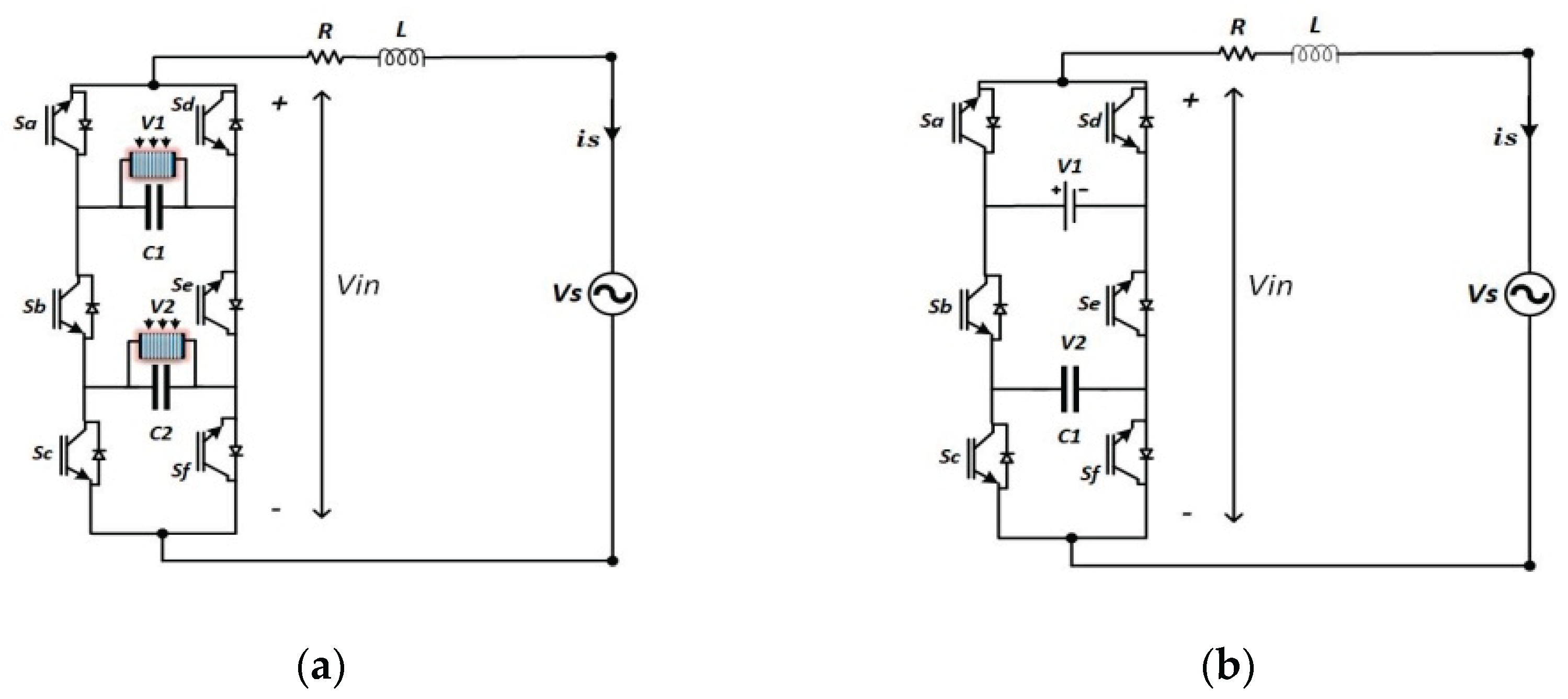
Figure 2.
(a) Proposed and (b) conventional CSC converter.
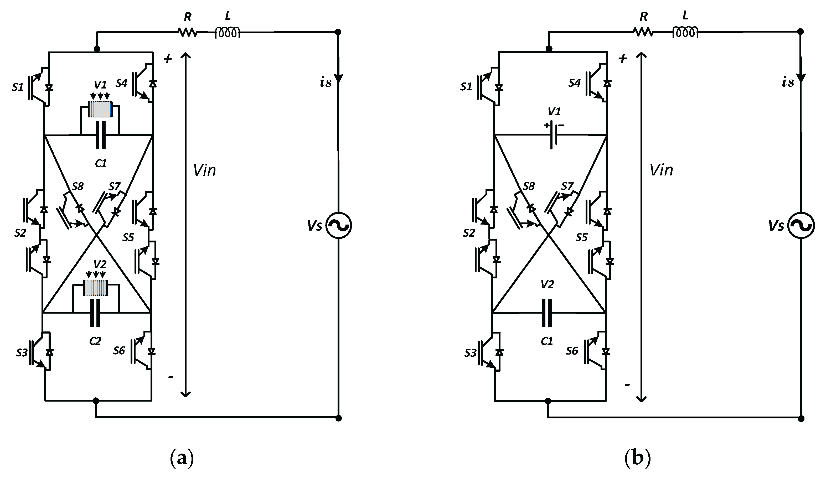
Figure 3.
MPC algorithm flowchart applied on 7L-PUC inverter.
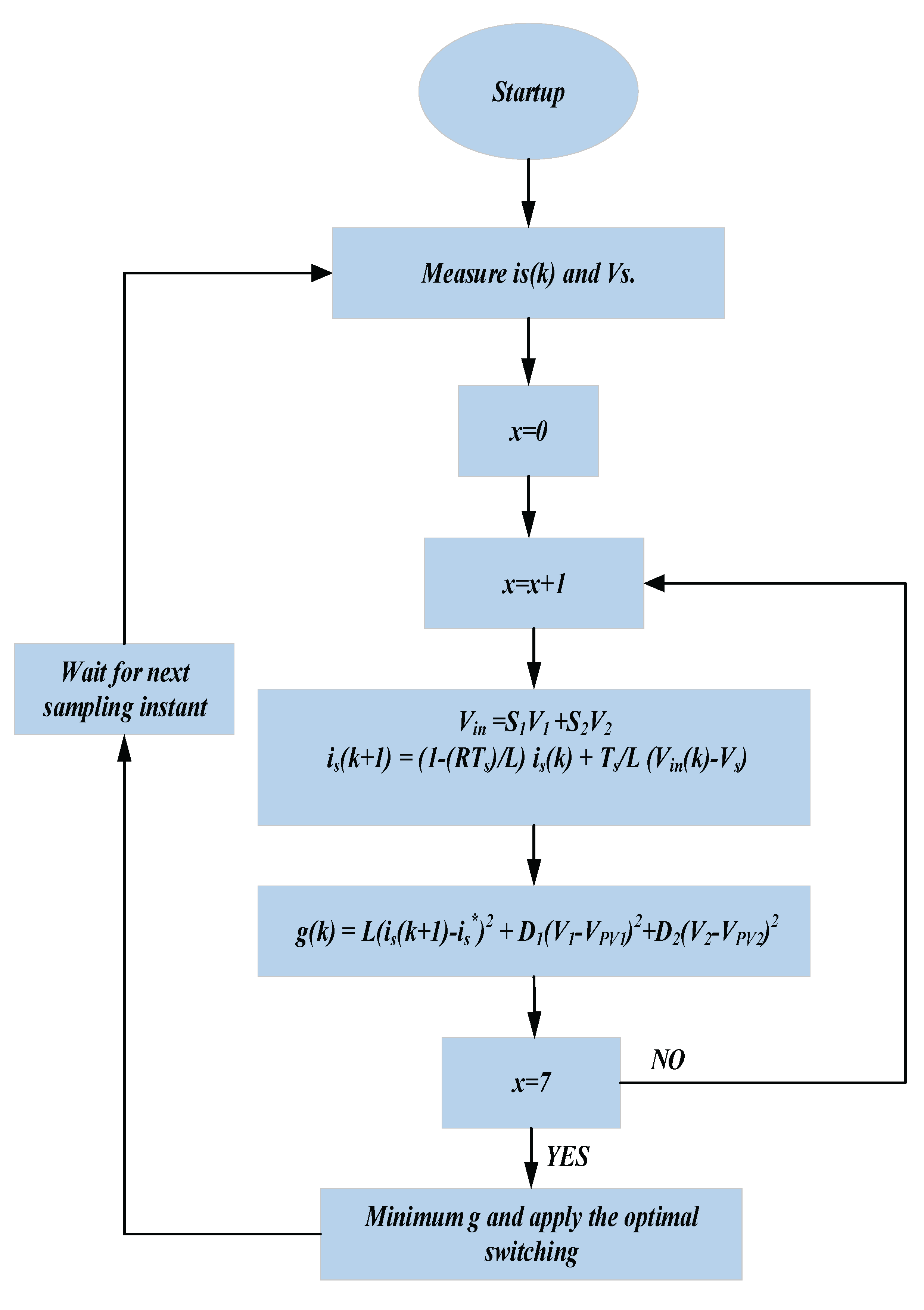
Figure 4.
Schematic control model applied on the proposed inverters.
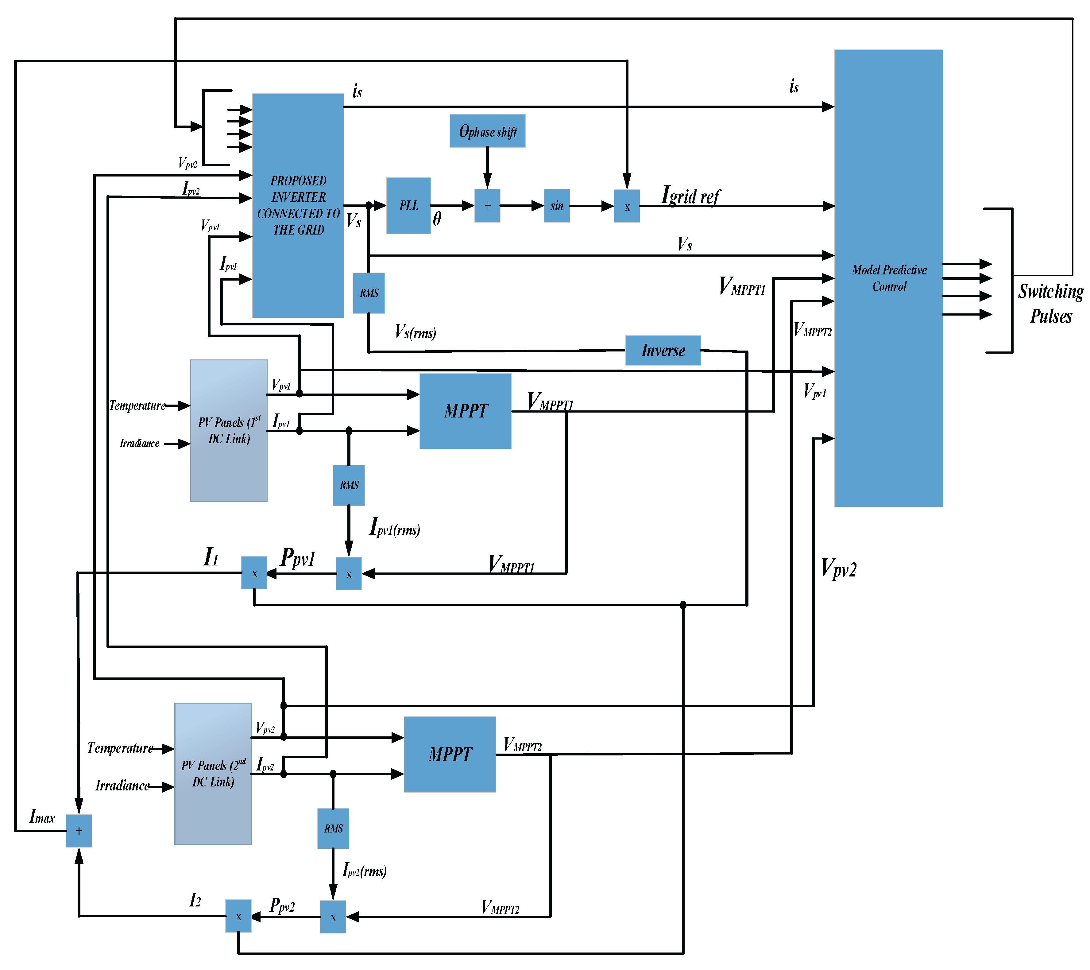
Figure 5.
MPC algorithm Flowchart applied on 9L-CSC inverter.
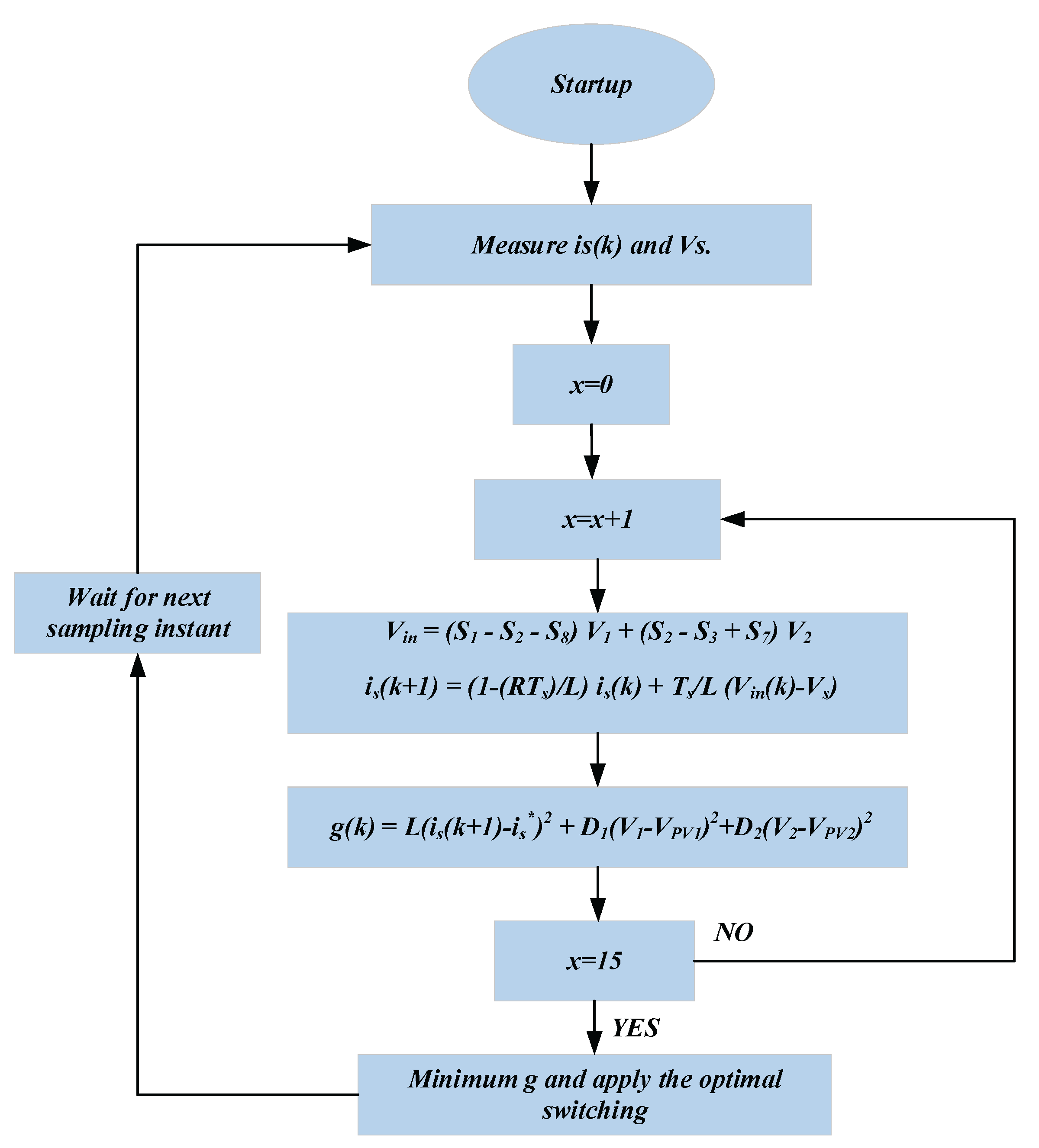
Figure 6.
Inverter 7-level output voltage in steady state operation - PUC inverter.
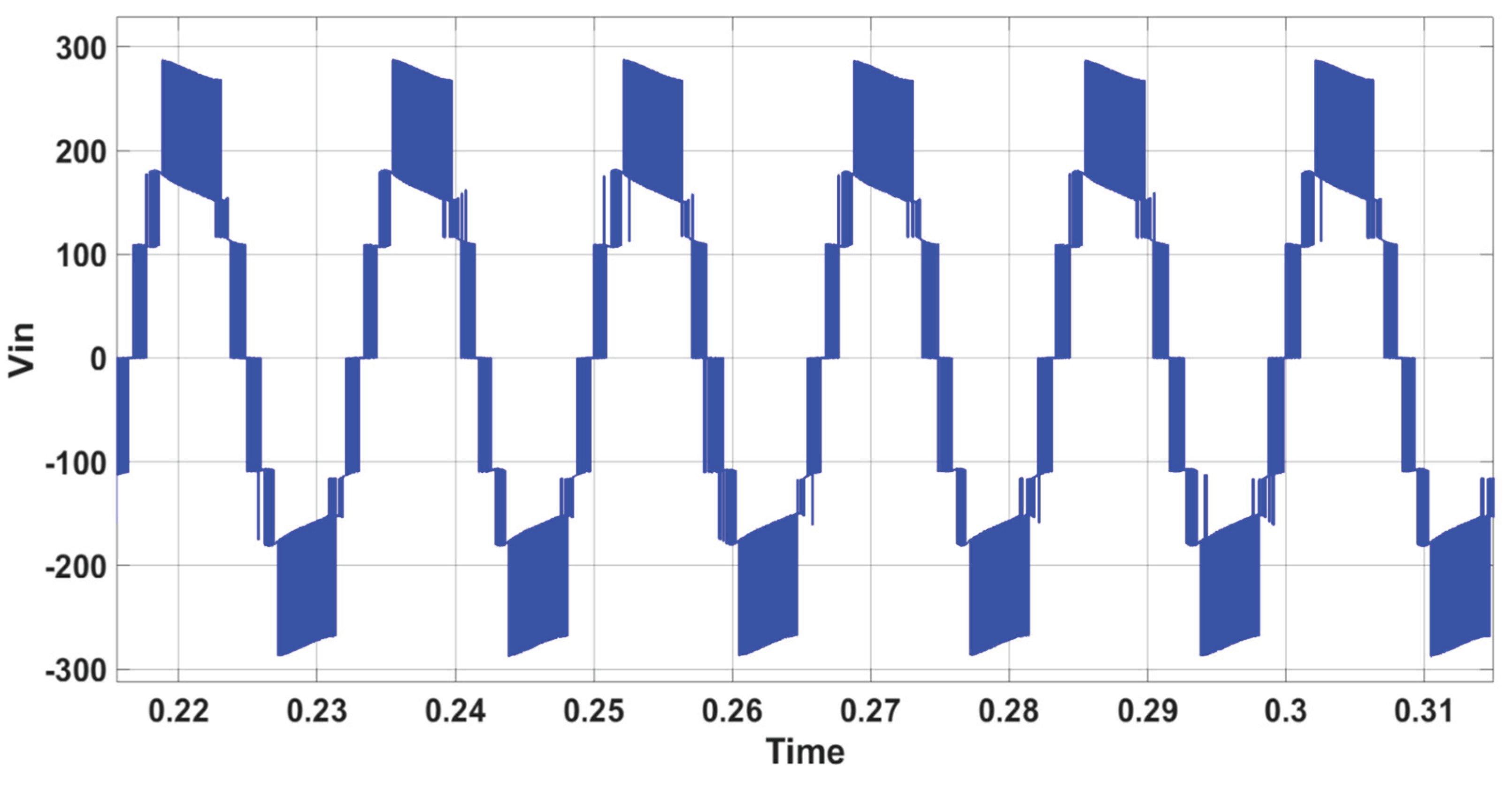
Figure 7.
AC waveforms is(A) (multiplied by 10), is* (A) (multiplied by 10), and Vs (V) in steady state operation - PUC inverter.
Figure 7.
AC waveforms is(A) (multiplied by 10), is* (A) (multiplied by 10), and Vs (V) in steady state operation - PUC inverter.
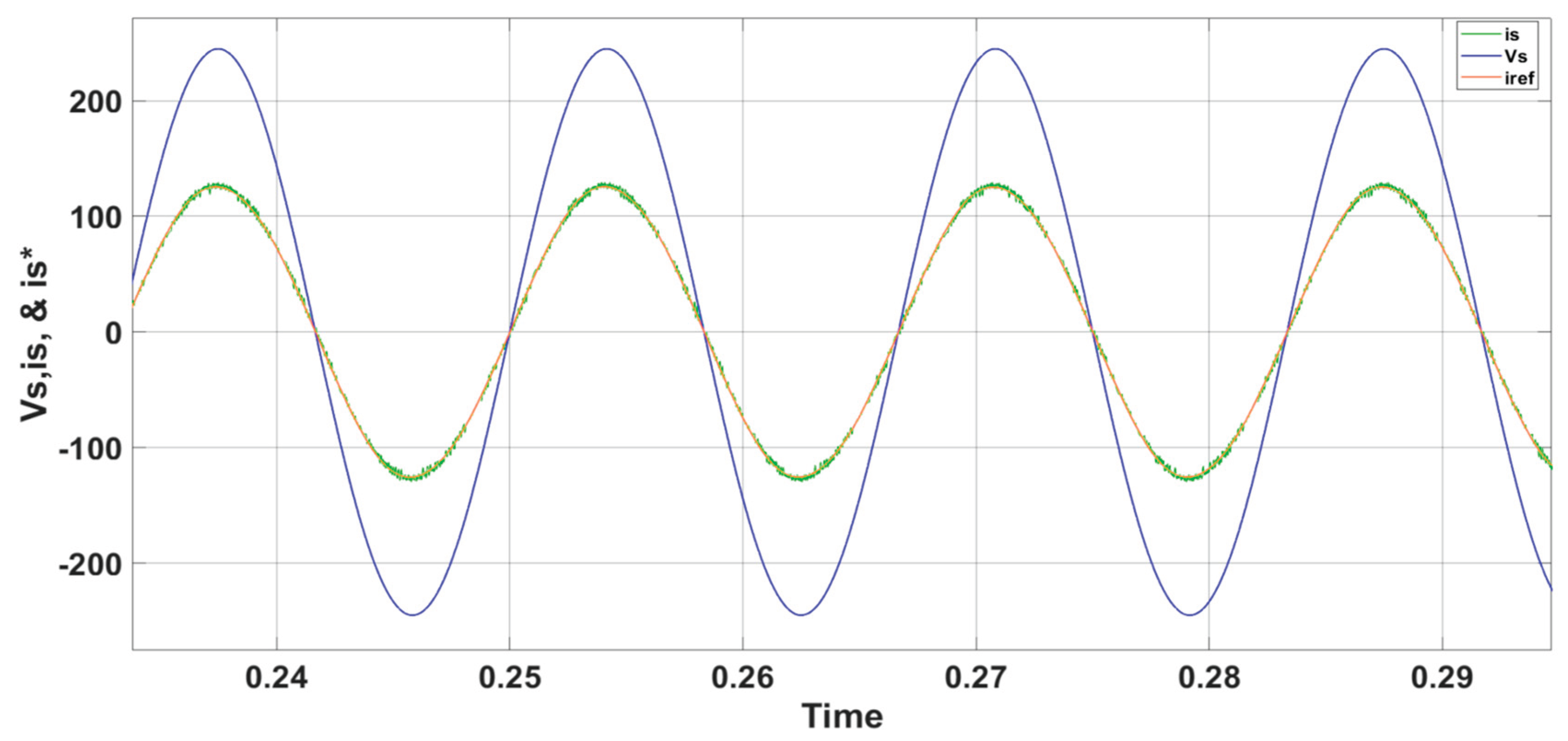
Figure 8.
Inverter 7-level output voltage during 10% grid voltage variation - PUC inverter.
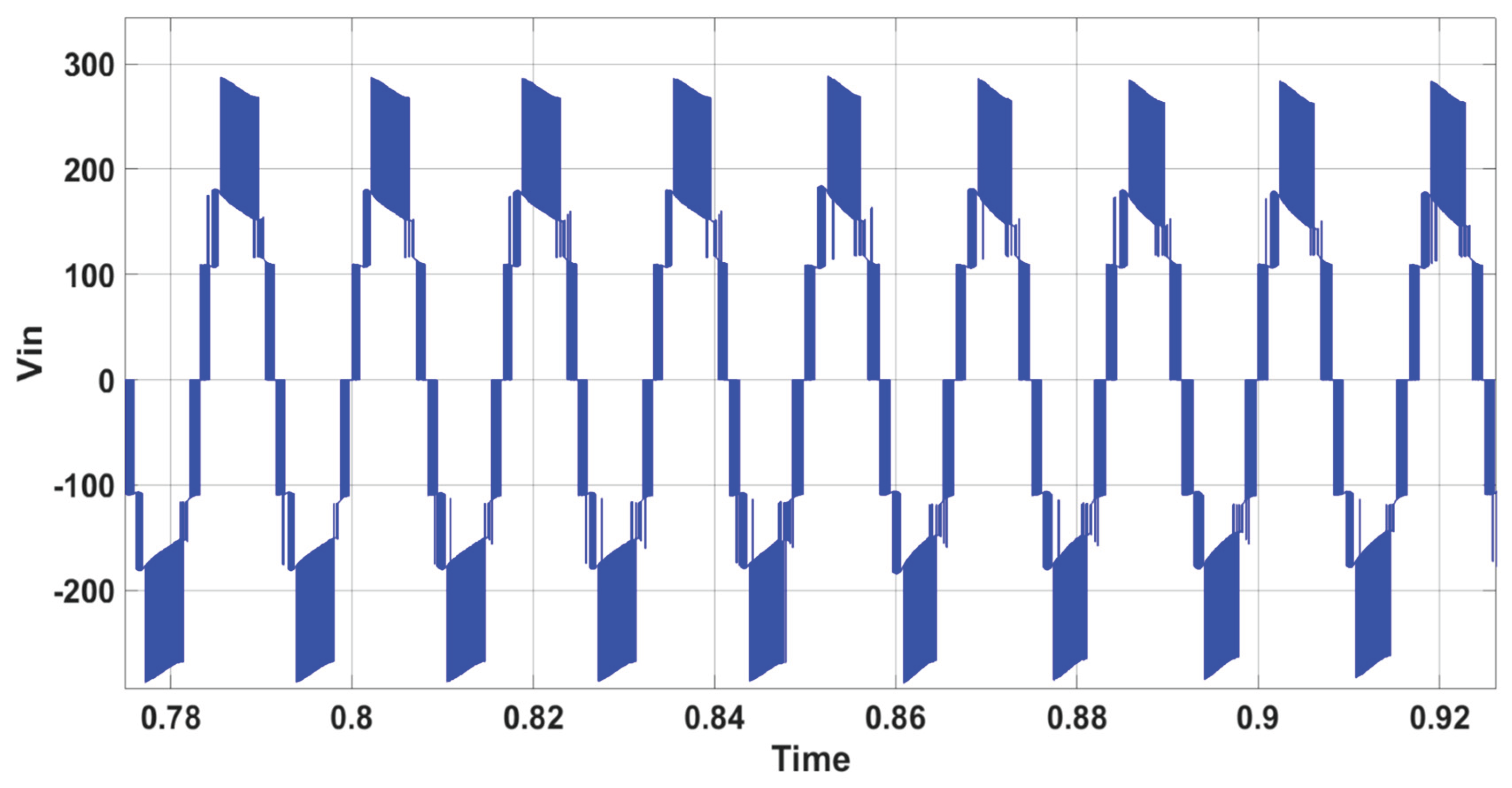
Figure 9.
AC waveforms is(A) (multiplied by 10), is* (A) (multiplied by 10), and Vs (V) during 10% grid voltage variation - PUC inverter.
Figure 9.
AC waveforms is(A) (multiplied by 10), is* (A) (multiplied by 10), and Vs (V) during 10% grid voltage variation - PUC inverter.
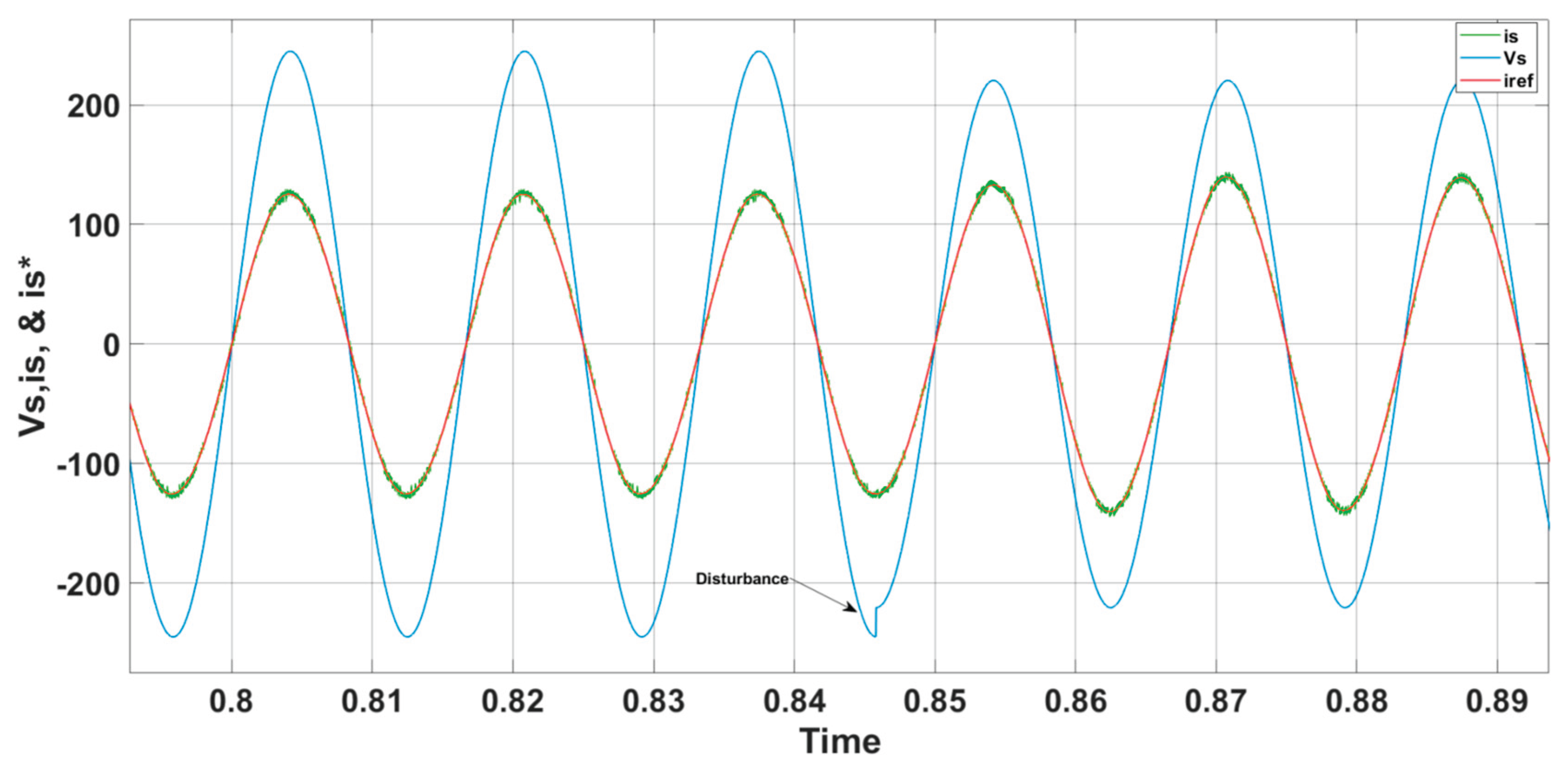
Figure 10.
Inverter 7-level output voltage during reactive power variation - PUC inverter.
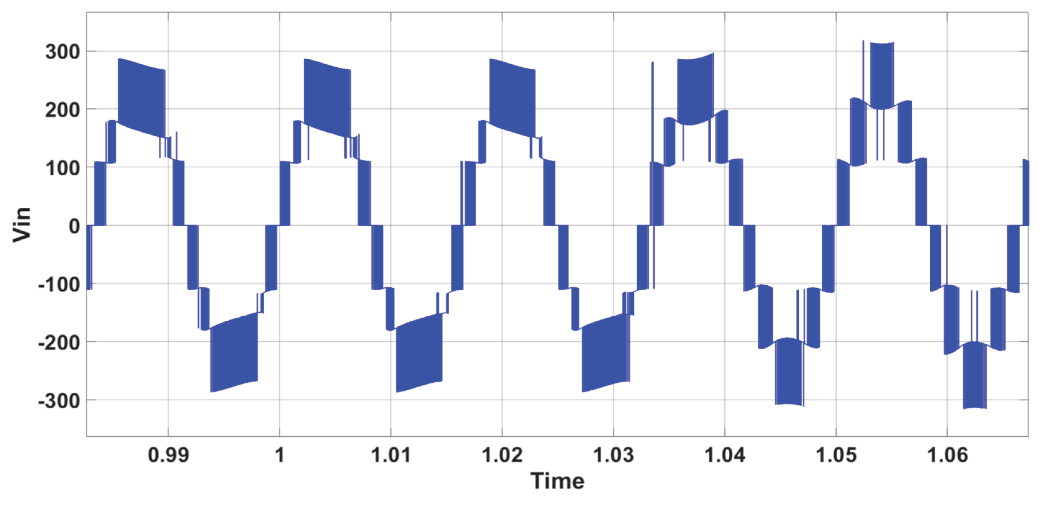
Figure 11.
AC waveforms is(A) (multiplied by 10), is* (A) (multiplied by 10), and Vs (V) during reactive power variation - PUC inverter.
Figure 11.
AC waveforms is(A) (multiplied by 10), is* (A) (multiplied by 10), and Vs (V) during reactive power variation - PUC inverter.
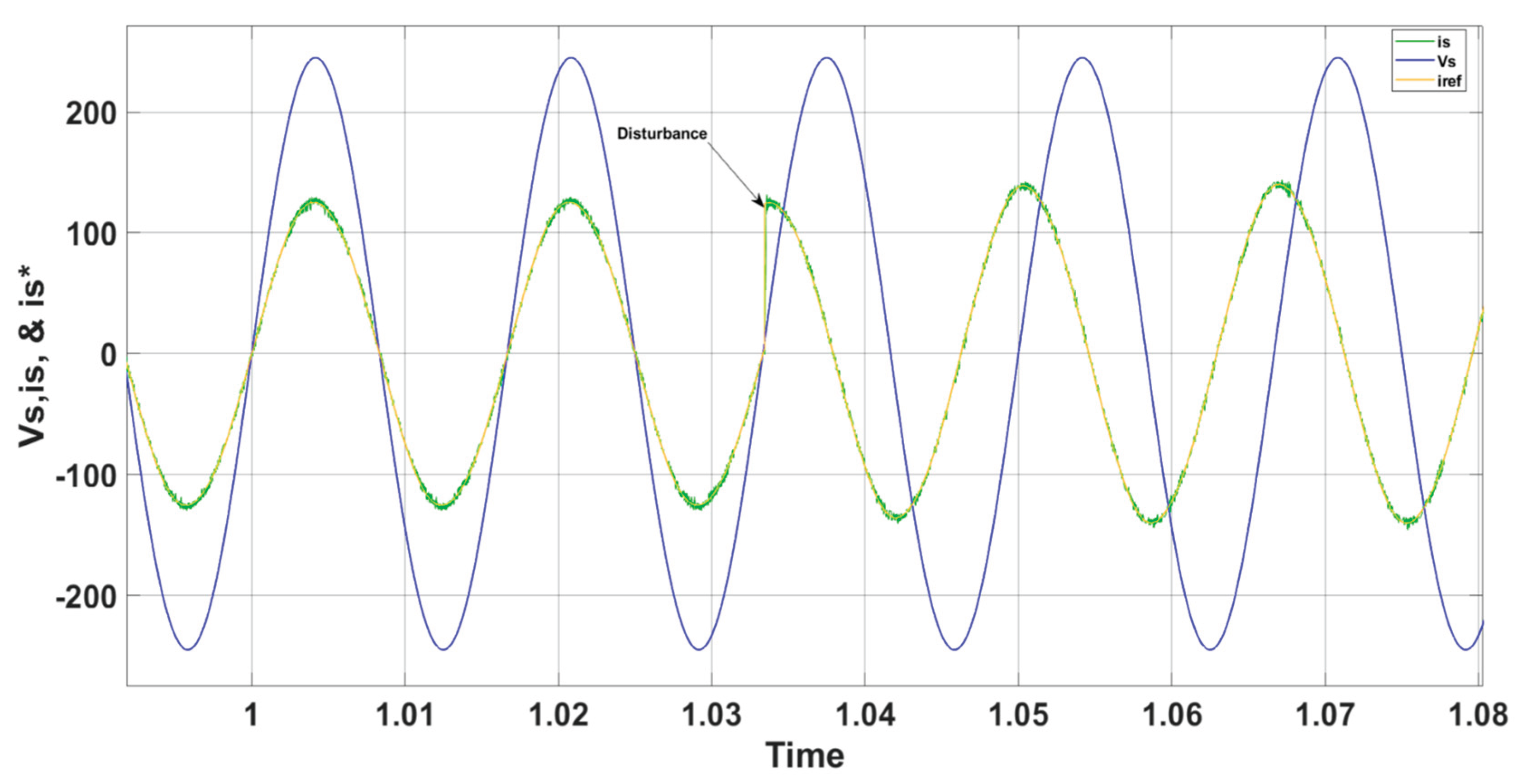
Figure 12.
Inverter 7-level output voltage during irradiation variation - PUC inverter.
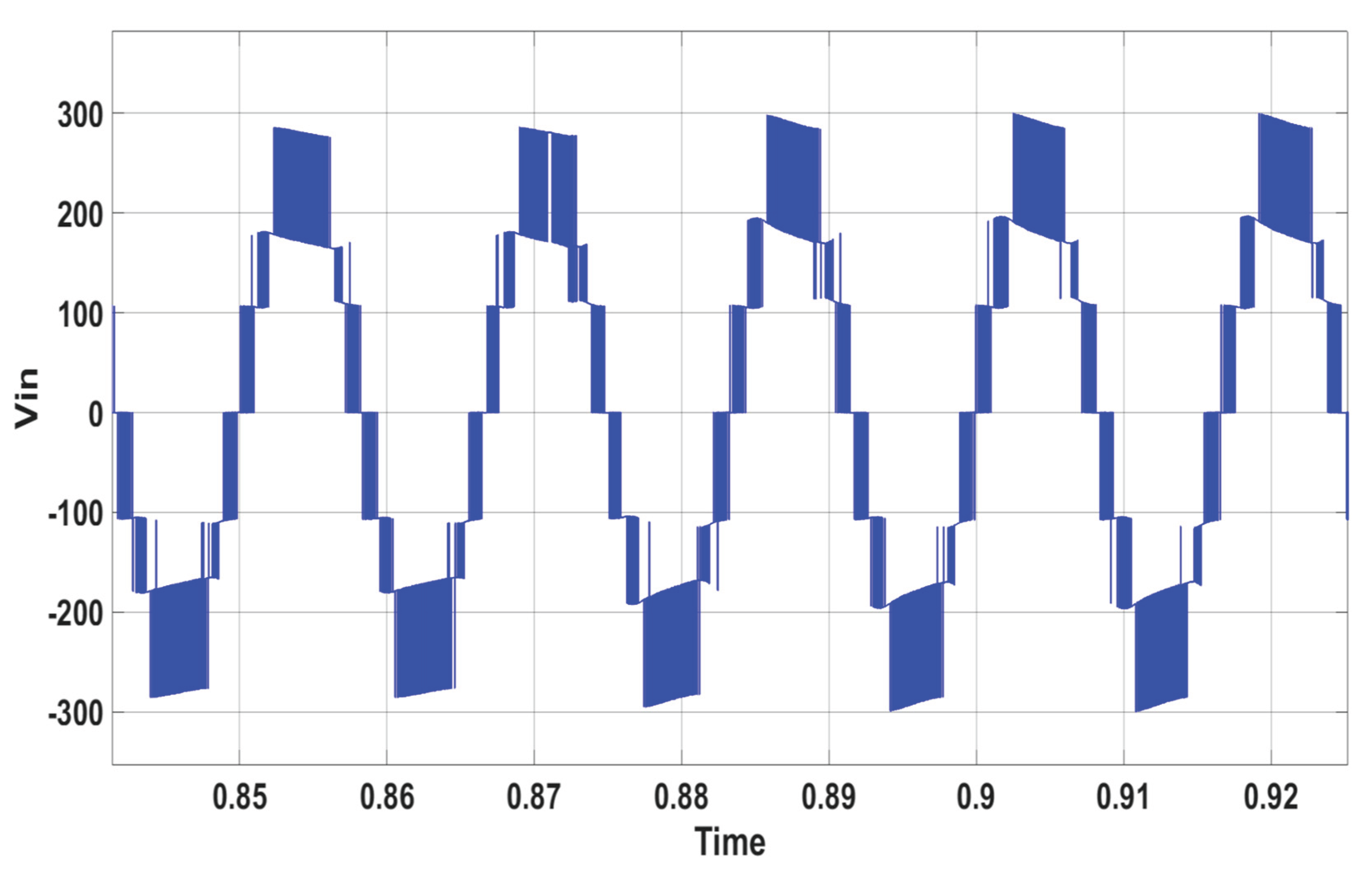
Figure 13.
AC waveforms is(A) (multiplied by 10), is* (A) (multiplied by 10), and Vs (V) during irradiation variation - PUC inverter.
Figure 13.
AC waveforms is(A) (multiplied by 10), is* (A) (multiplied by 10), and Vs (V) during irradiation variation - PUC inverter.
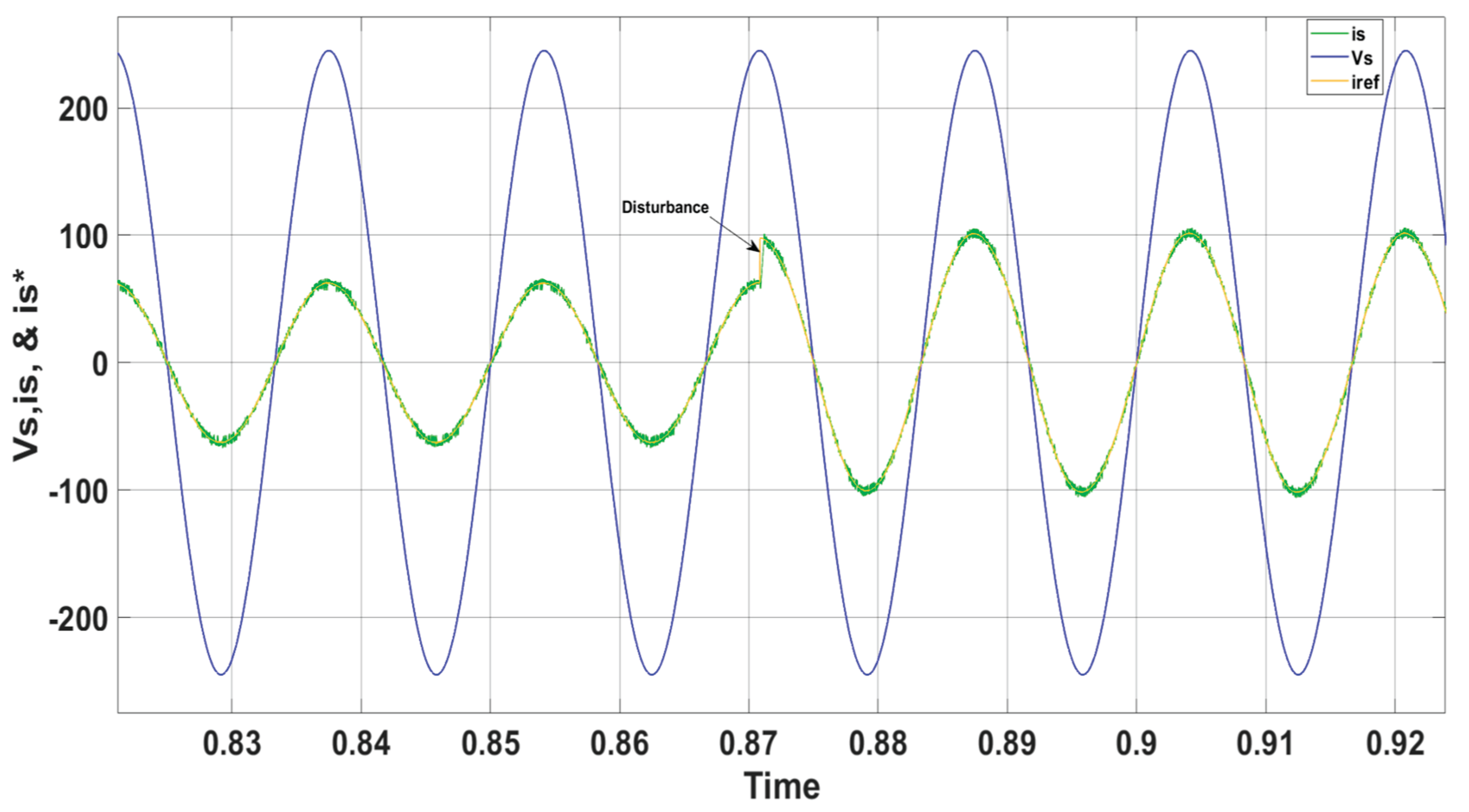
Figure 14.
PV power during irradiation variation - PUC inverter.
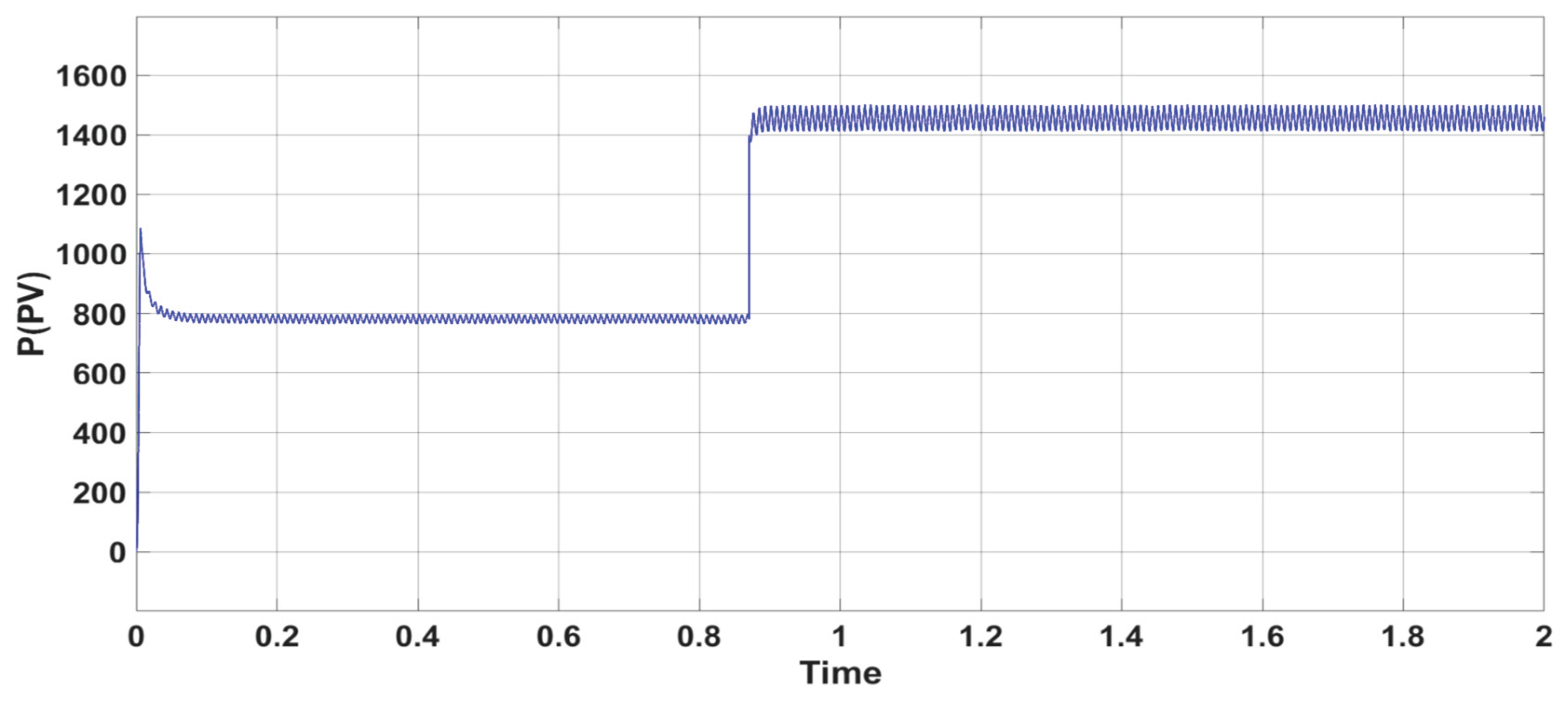
Figure 15.
VDC1 and Vmppt(DC1) during irradiation variation - PUC inverter.
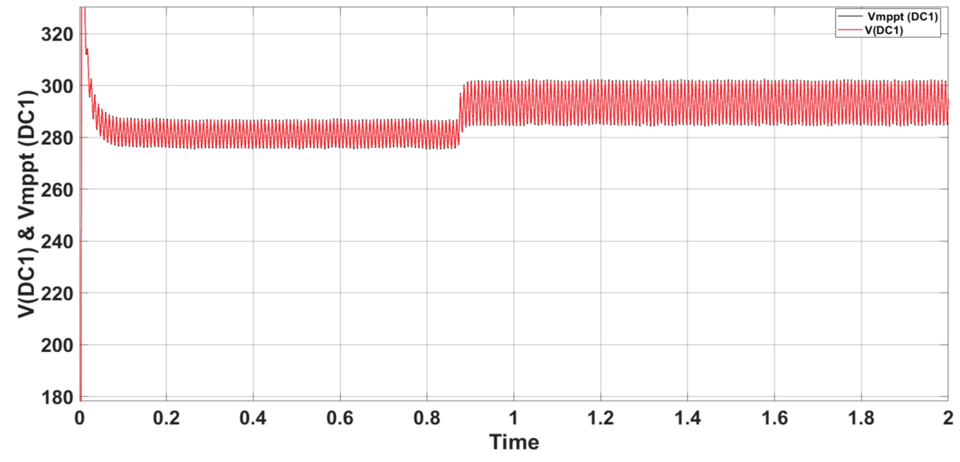
Figure 16.
VDC2 and Vmppt(DC2) during irradiation variation - PUC inverter.
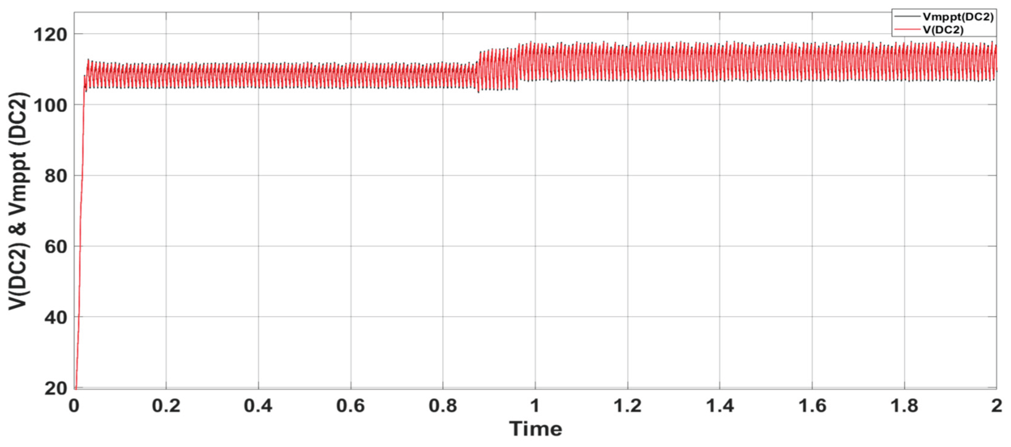
Figure 17.
Inverter 7-level output voltage in steady state operation – CSC inverter.
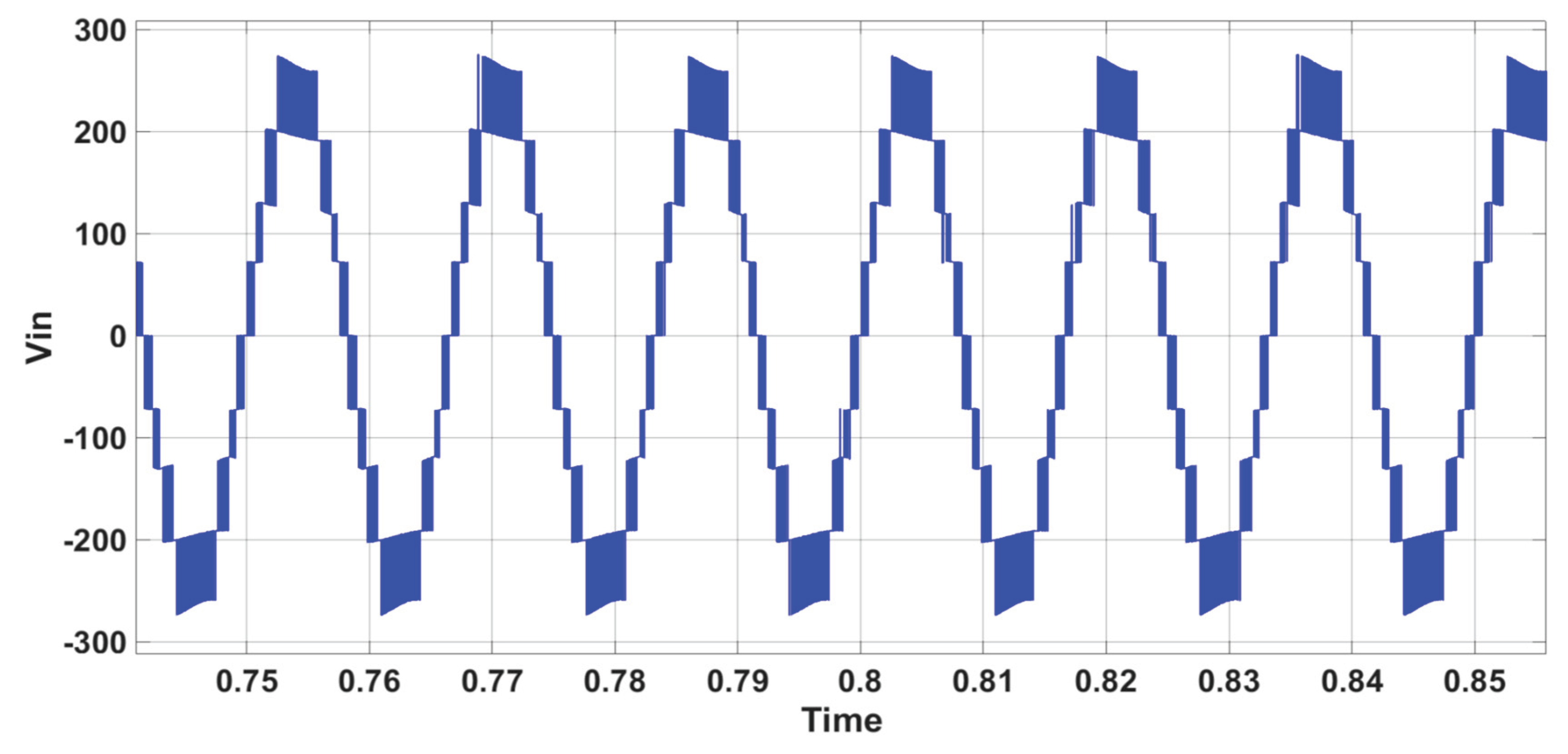
Figure 18.
AC waveforms is(A) (multiplied by 10), is* (A) (multiplied by 10), and Vs (V) in steady state operation – CSC inverter.
Figure 18.
AC waveforms is(A) (multiplied by 10), is* (A) (multiplied by 10), and Vs (V) in steady state operation – CSC inverter.
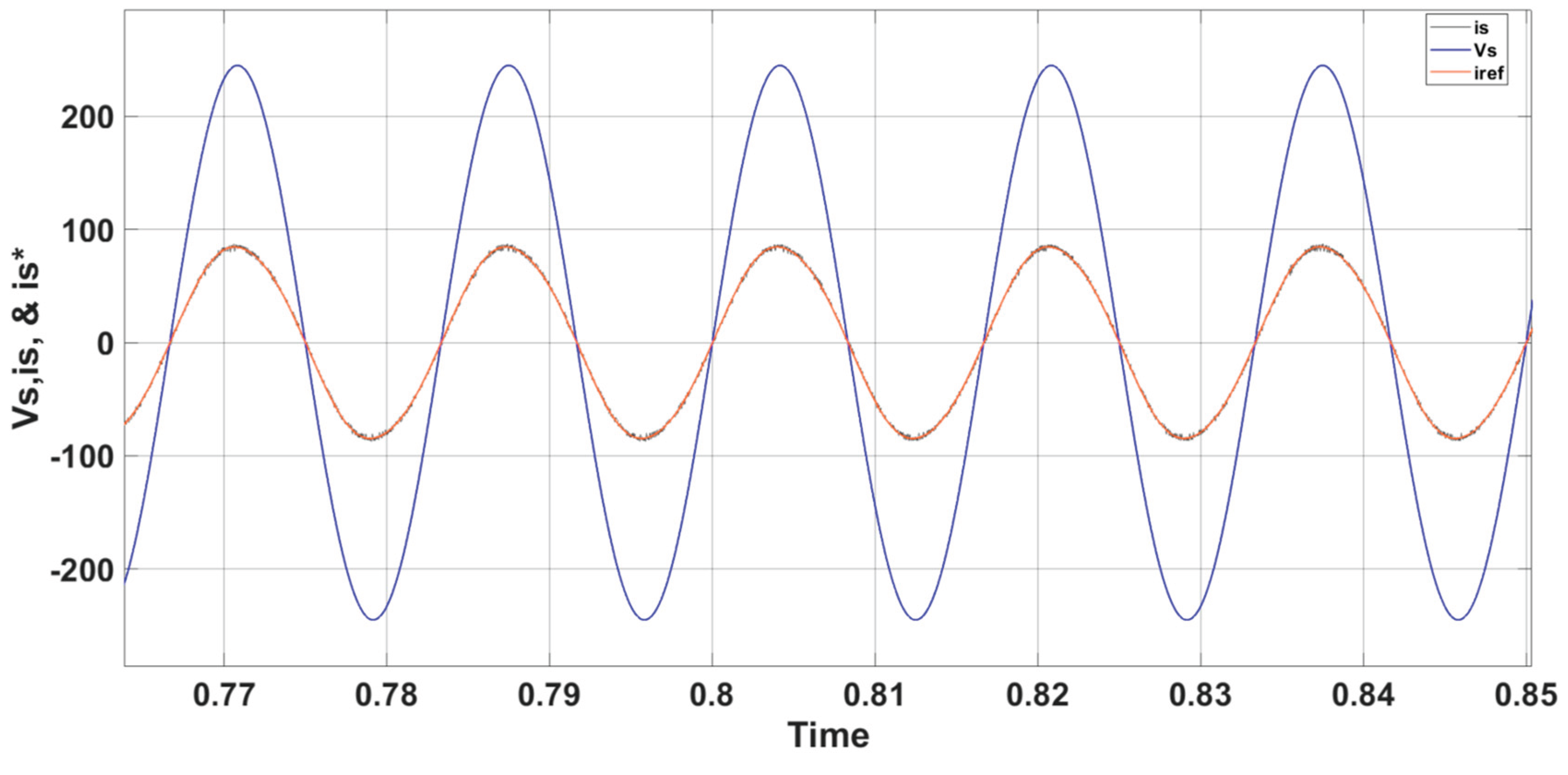
Figure 19.
Inverter 7-level output voltage during 10% grid voltage variation – CSC inverter.
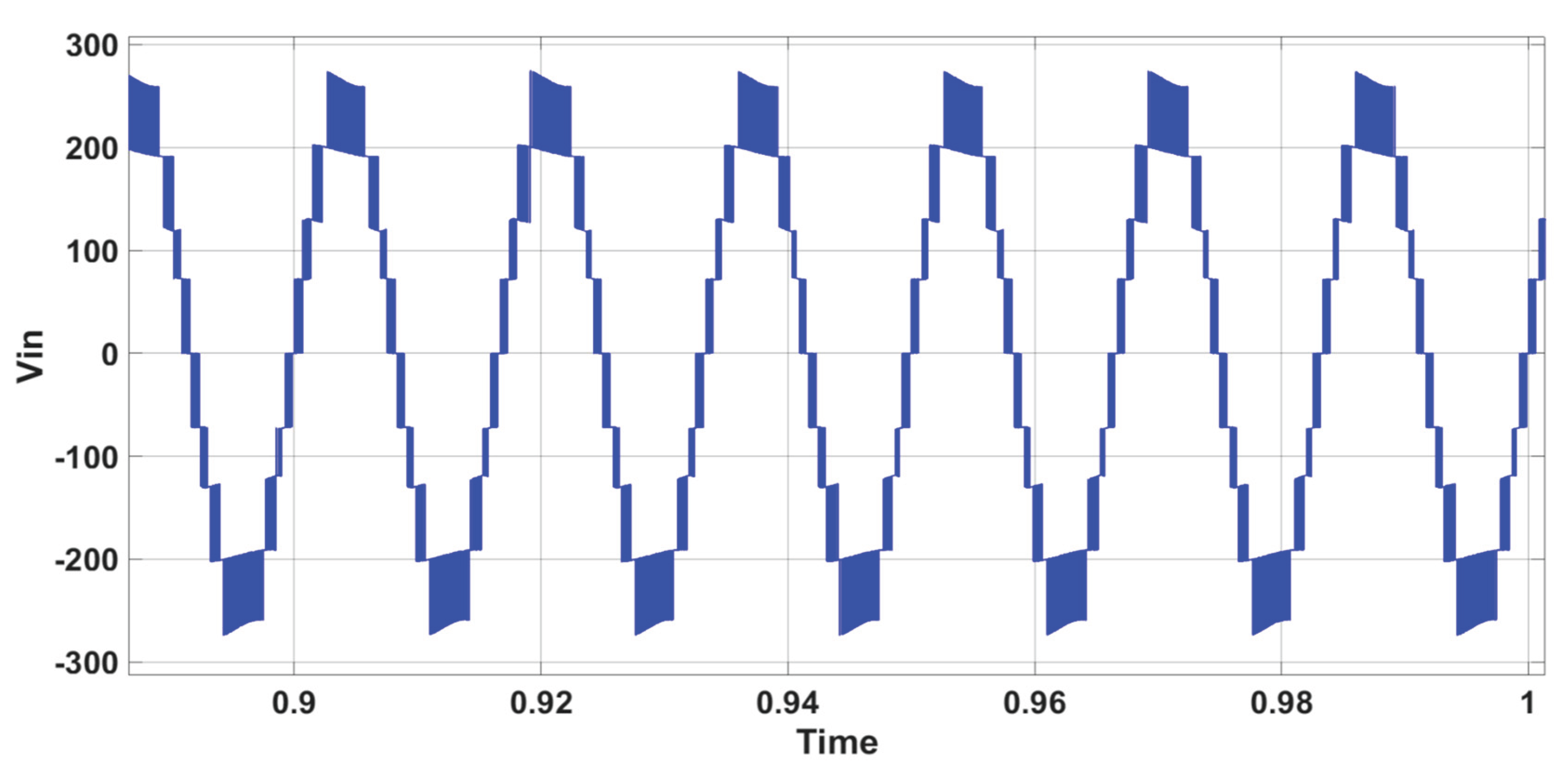
Figure 20.
AC waveforms is(A) (multiplied by 10), is* (A) (multiplied by 10), and Vs (V) during 10% grid voltage variation – CSC inverter.
Figure 20.
AC waveforms is(A) (multiplied by 10), is* (A) (multiplied by 10), and Vs (V) during 10% grid voltage variation – CSC inverter.
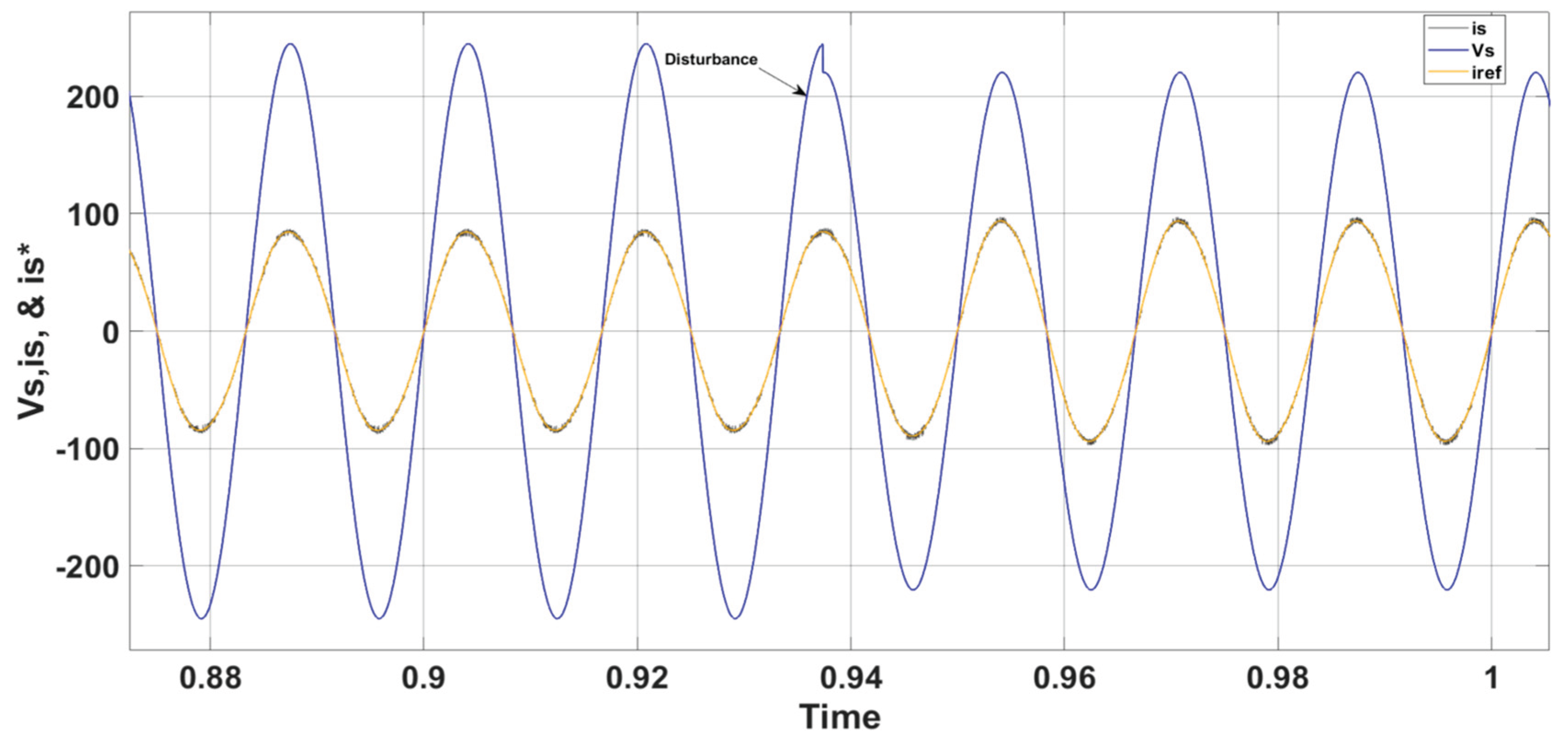
Figure 21.
Inverter 7-level output voltage during reactive power variation - CSC inverter.
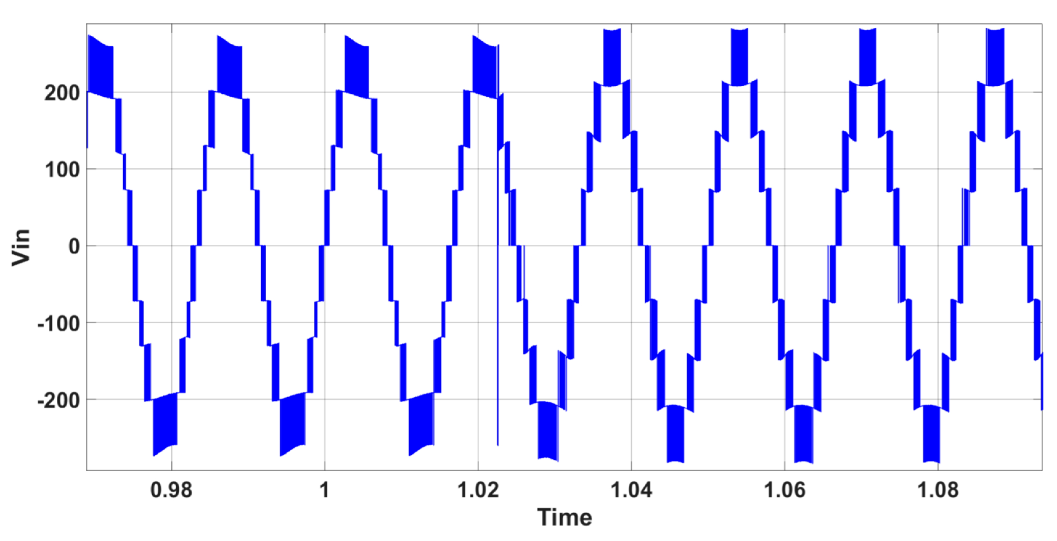
Figure 22.
AC waveforms is(A) (multiplied by 10), is* (A) (multiplied by 10), and Vs (V) during reactive power variation - CSC inverter.
Figure 22.
AC waveforms is(A) (multiplied by 10), is* (A) (multiplied by 10), and Vs (V) during reactive power variation - CSC inverter.
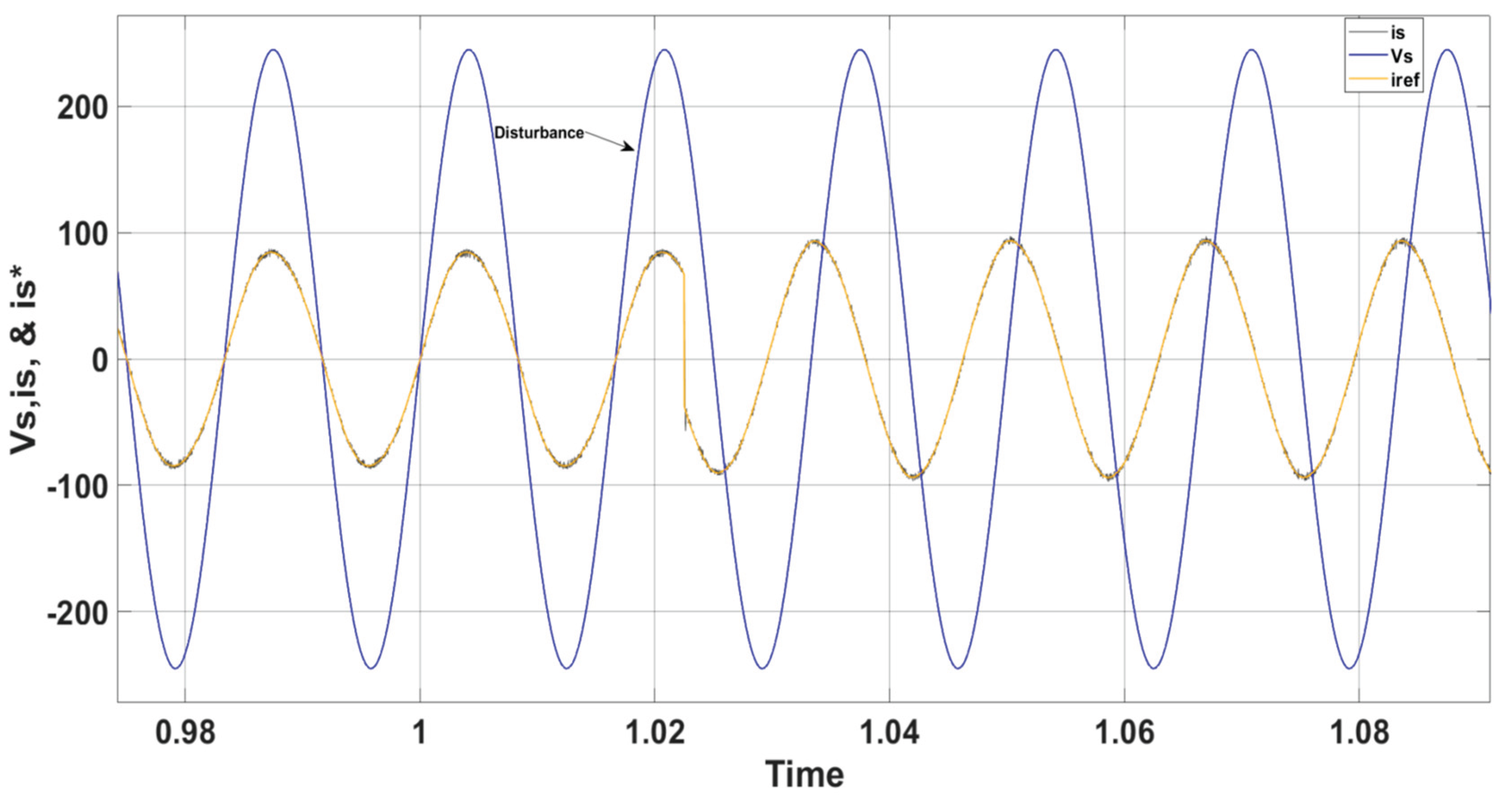
Figure 23.
Inverter 7-level output voltage during irradiation variation - CSC inverter.
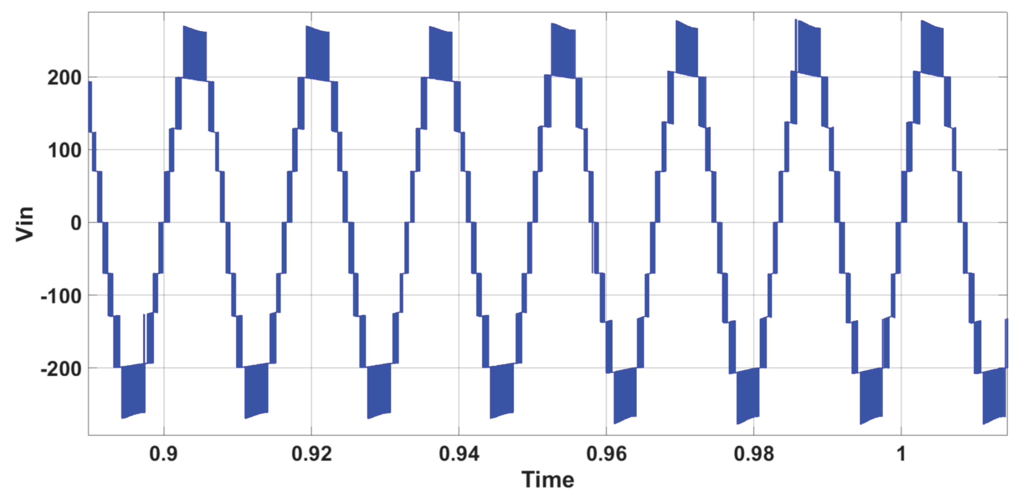
Figure 24.
AC waveforms is(A) (multiplied by 10), is* (A) (multiplied by 10), and Vs (V) during irradiation variation - CSC inverter.
Figure 24.
AC waveforms is(A) (multiplied by 10), is* (A) (multiplied by 10), and Vs (V) during irradiation variation - CSC inverter.
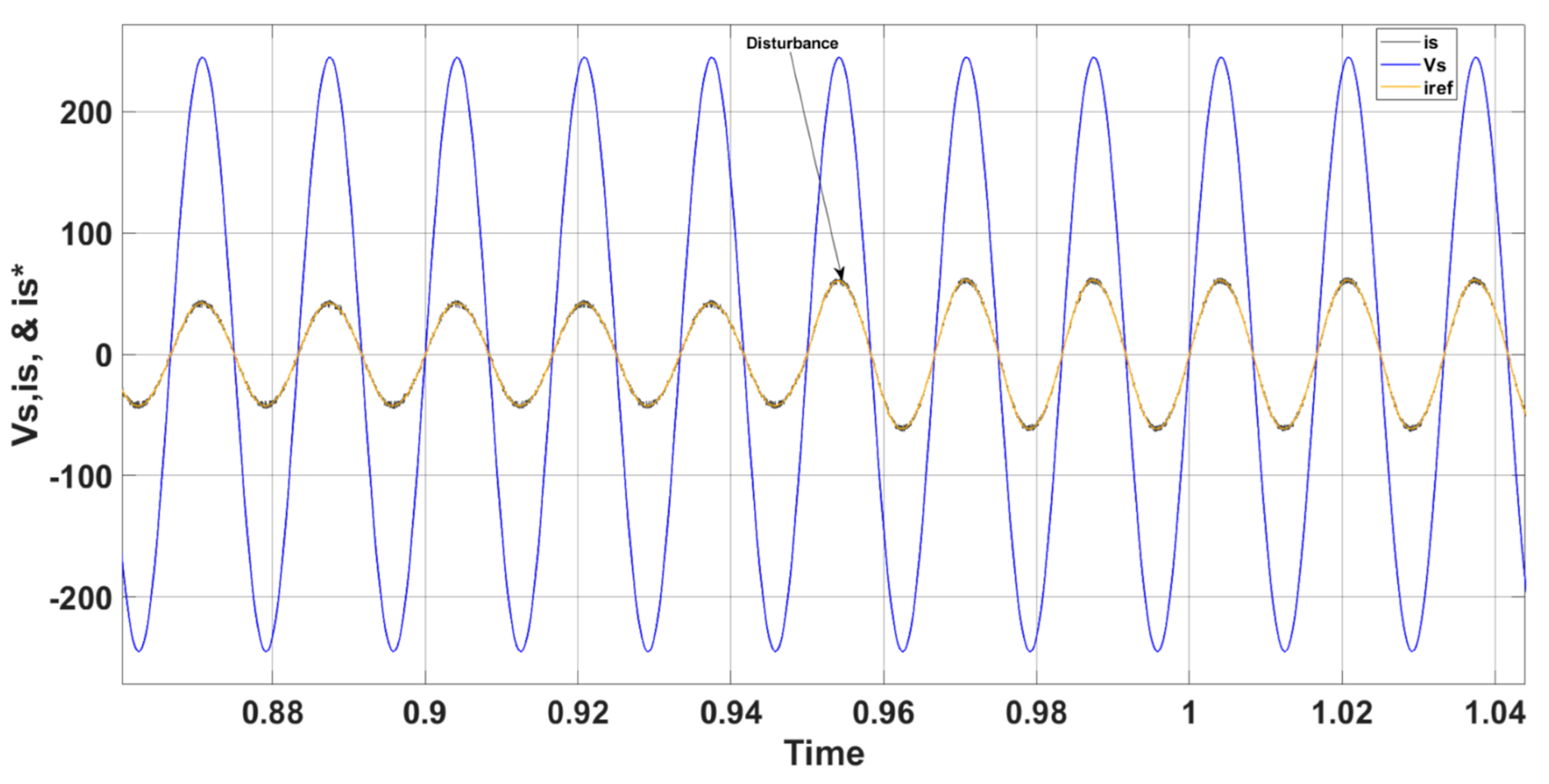
Figure 25.
PV power during irradiation variation - CSC inverter.
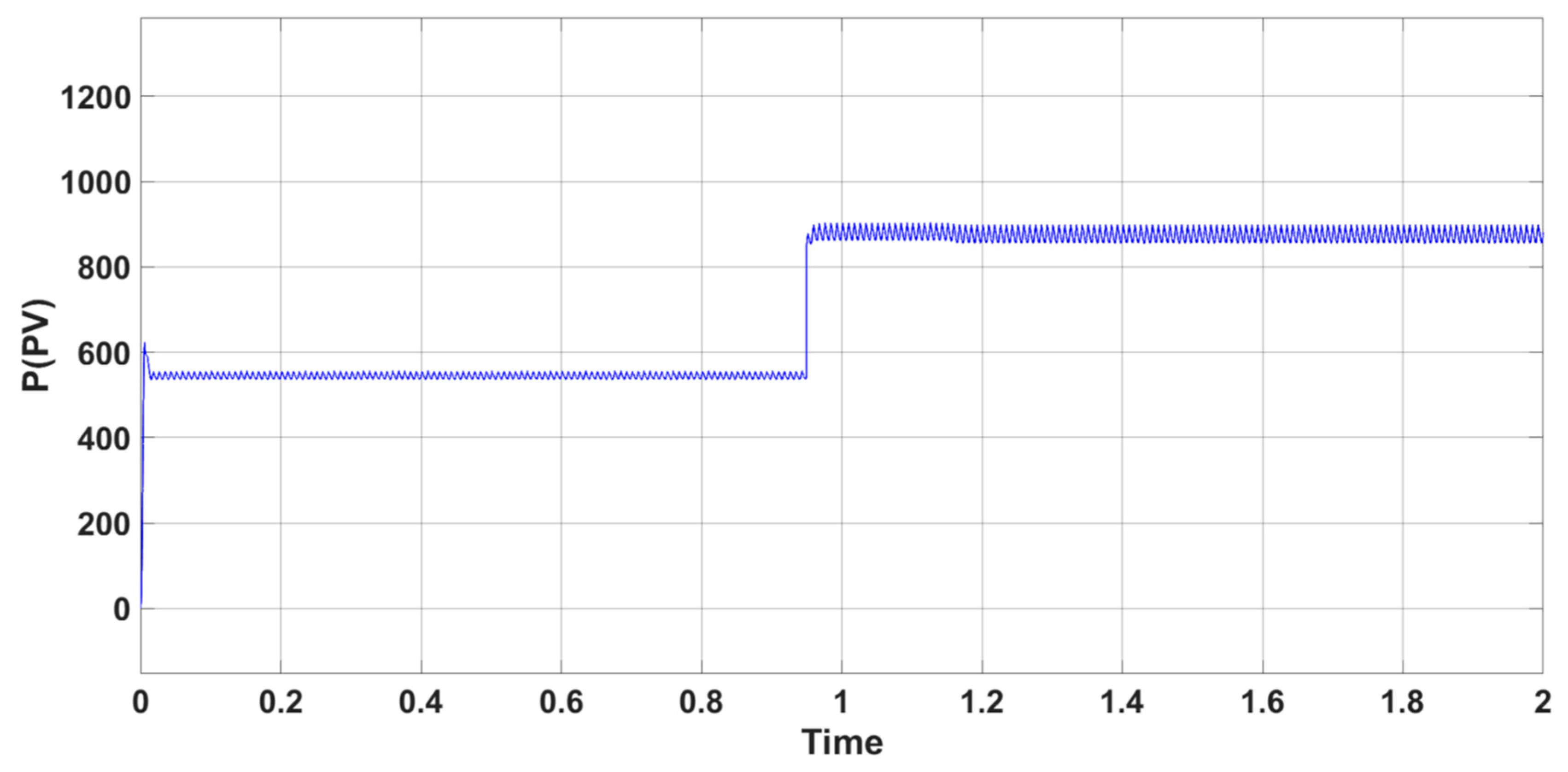
Figure 26.
VDC1 and Vmppt(DC1) during irradiation variation - CSC inverter.
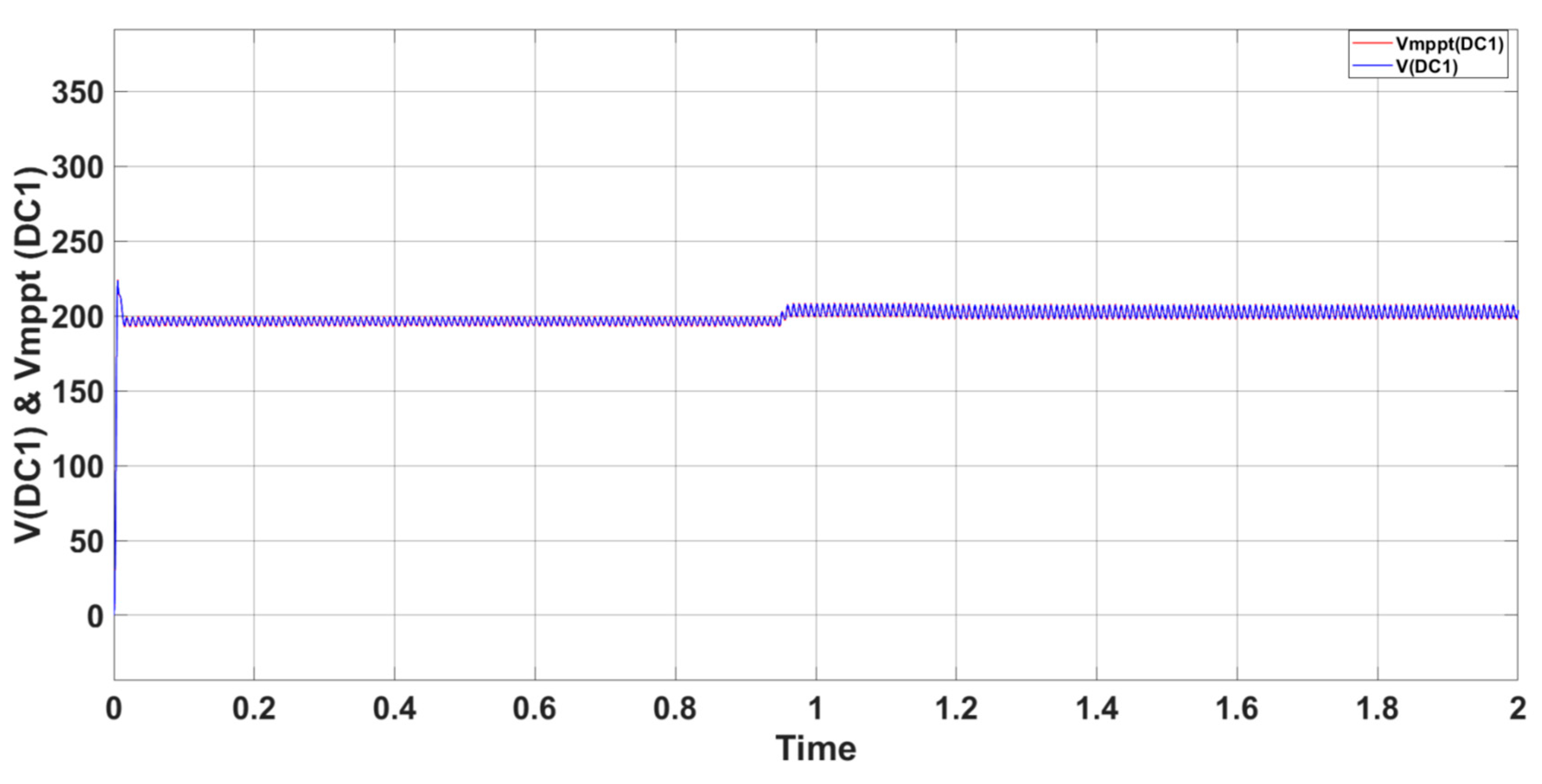
Figure 27.
VDC2 and Vmppt(DC2) during irradiation variation - CSC inverter.
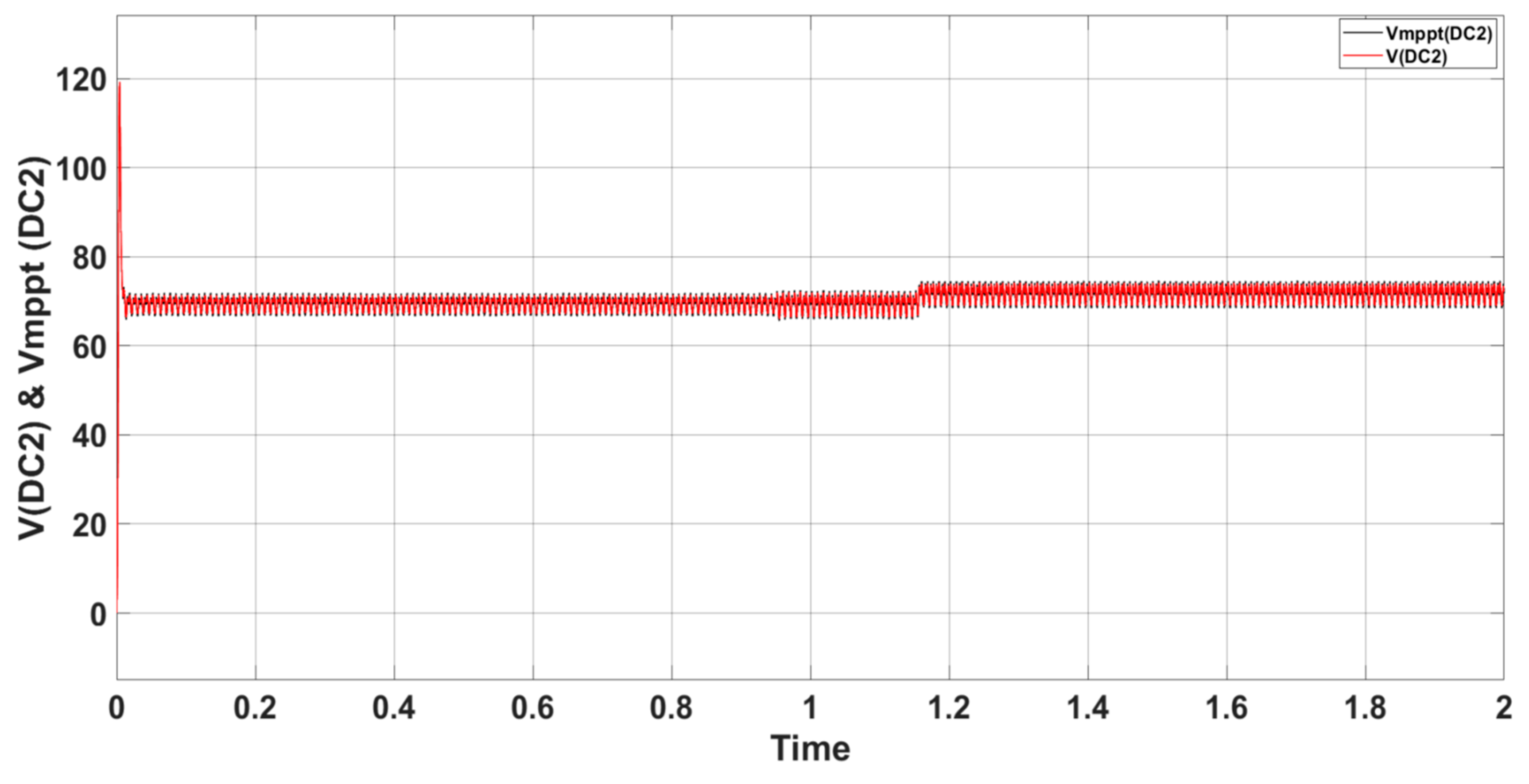

Table 1.
PUC Inverter all Possible Switching States.
| States | Sa | Sb | Sc |
Vin (Output Voltage) |
| 1 | 1 | 0 | 0 | V1 |
| 2 | 1 | 0 | 1 | V1-V2 |
| 3 | 1 | 1 | 0 | V2 |
| 4 | 1 | 1 | 1 | 0 |
| 5 | 0 | 0 | 0 | 0 |
| 6 | 0 | 0 | 1 | -V2 |
| 7 | 0 | 1 | 0 | V2-V1 |
| 8 | 0 | 1 | 1 | -V1 |
Table 2.
Voltage Levels Values Produced by 7-Level PUC Inverter (V2=E & V1=3V2=3E).
| States | Sa | Sb | Sc |
Vin (Output Voltage) |
Vin (Output Voltage Value) |
| 1 | 1 | 0 | 0 | V1 | +3E |
| 2 | 1 | 0 | 1 | V1-V2 | 3E-E=+2E |
| 3 | 1 | 1 | 0 | V2 | +E |
| 4 | 1 | 1 | 1 | 0 | 0 |
| 5 | 0 | 0 | 0 | 0 | 0 |
| 6 | 0 | 0 | 1 | -V2 | -E |
| 7 | 0 | 1 | 0 | V2-V1 | E-3E=-2E |
| 8 | 0 | 1 | 1 | -V1 | -3E |
Table 3.
Voltage Levels Values Produced by 5-Level PUC Inverter (V2=E & V1=2V2=2E).
| States | Sa | Sb | Sc |
Vin (Output Voltage) |
Vin (Output Voltage Value) |
| 1 | 1 | 0 | 0 | V1 | +2E |
| 2 | 1 | 0 | 1 | V1-V2 | 2E-E=+E |
| 3 | 1 | 1 | 0 | V2 | +E |
| 4 | 1 | 1 | 1 | 0 | 0 |
| 5 | 0 | 0 | 0 | 0 | 0 |
| 6 | 0 | 0 | 1 | -V2 | -E |
| 7 | 0 | 1 | 0 | V2-V1 | E-2E=-E |
| 8 | 0 | 1 | 1 | -V1 | -2E |
Table 4.
Voltage Levels Values Produced by 3-Level PUC Inverter (V1=V2=E).
| States | Sa | Sb | Sc |
Vin (Output Voltage) |
Vin (Output Voltage Value) |
| 1 | 1 | 0 | 0 | V1 | +E |
| 2 | 1 | 0 | 1 | V1-V2 | E-E=0 |
| 3 | 1 | 1 | 0 | V2 | +E |
| 4 | 1 | 1 | 1 | 0 | 0 |
| 5 | 0 | 0 | 0 | 0 | 0 |
| 6 | 0 | 0 | 1 | -V2 | -E |
| 7 | 0 | 1 | 0 | V2-V1 | E-E=0 |
| 8 | 0 | 1 | 1 | -V1 | -E |
Table 5.
Voltage Levels Values Produced by 9-Level CSC Inverter (V2=E & V1=3V2=3E).
| States | S1 | S2 | S3 | S4 | S5 | S6 | S7 | S8 |
Vin (Output Voltage) |
Vin (Output Voltage Value) |
Capacitor Charging State |
| 1 | 1 | 0 | 0 | 0 | 0 | 1 | 1 | 0 | V1+ V2 | 3E+E=4E | Charged |
| 2 | 1 | 0 | 0 | 0 | 1 | 1 | 0 | 0 | V1 | 3E | By passed |
| 3 | 1 | 0 | 1 | 0 | 0 | 0 | 1 | 0 | V1 | 3E | By passed |
| 4 | 1 | 0 | 1 | 0 | 1 | 0 | 0 | 0 | V1-V2 | 3E-E=2E | Discharged |
| 5 | 0 | 0 | 0 | 1 | 0 | 1 | 1 | 0 | V2 | E | Charged |
| 6 | 1 | 1 | 0 | 0 | 0 | 1 | 0 | 0 | V2 | E | Charged |
| 7 | 0 | 0 | 1 | 1 | 0 | 0 | 1 | 0 | 0 | 0 | By passed |
| 8 | 1 | 1 | 1 | 0 | 0 | 0 | 0 | 0 | 0 | 0 | By passed |
| 9 | 0 | 0 | 0 | 1 | 1 | 1 | 0 | 0 | 0 | 0 | By passed |
| 10 | 1 | 0 | 0 | 0 | 0 | 1 | 0 | 1 | 0 | 0 | By passed |
| 11 | 0 | 0 | 1 | 1 | 1 | 0 | 0 | 0 | -V2 | -E | Discharged |
| 12 | 1 | 0 | 1 | 0 | 0 | 0 | 0 | 1 | -V2 | -E | Discharged |
| 13 | 0 | 1 | 0 | 1 | 0 | 1 | 0 | 0 | -V1+ V2 | -3E+E=-2E | Charged |
| 14 | 0 | 0 | 0 | 1 | 0 | 1 | 0 | 1 | -V1 | -3E | By passed |
| 15 | 0 | 1 | 1 | 1 | 0 | 0 | 0 | 0 | -V1 | -3E | By passed |
| 16 | 0 | 0 | 1 | 1 | 0 | 0 | 0 | 1 | -V1- V2 | -3E-E=-4E | Discharged |
Table 6.
Simplified Switching States.
| States | S1 | S2 |
Vin (Output Voltage) |
| 1 | 1 | 0 | V1 |
| 2 | 1 | -1 | V1-V2 |
| 3 | 0 | 1 | V2 |
| 4 | 0 | 0 | 0 |
| 5 | 0 | 0 | 0 |
| 6 | 0 | -1 | -V2 |
| 7 | -1 | 1 | V2-V1 |
| 8 | -1 | 0 | -V1 |
Table 7.
System’s Parameters for PUC Inverter.
| Sampling time | 20µsec |
| DC bus voltage (PV panels) | 300V-315V (9 panels in series) |
| DC link voltage (PV panels) | 99-105V (3 panels in series) |
|
DC capacitor C |
1000µF |
| Line inductor L | 2.5mH |
| Parasitic Resistor (r) | 0.1Ω |
| AC grid voltage (Vrms) | 300V |
| Frequency | 60Hz |
Table 8.
System’s Parameters for CSC Inverter.
| Sampling time | 20µsec |
| DC bus voltage (PV panels) | 200V-210V (6 panels in series) |
| DC link voltage (PV panels) | 66-70V (2 panels in series) |
|
DC capacitor C |
1000µF |
| Line inductor L | 2.5mH |
| Parasitic Resistor (r) | 0.1Ω |
| AC grid voltage (Vrms) | 300V |
| Frequency | 60Hz |
Table 9.
Comparison between PUC inverter and CSC inverter.
| Comparison Criteria | Packed U-Cell (PUC) Inverter | Cross Switches Cell (CSC) Inverter |
| Number of Voltage Levels | Up to 7 levels | Up to 9 levels |
| Number of DC Sources | Single DC source | Single DC source |
| Number of DC busses | Two: isolated DC source functions as the primary DC link and a capacitor functions as a secondary, auxiliary DC link | Two: isolated DC source functions as the primary DC link and a capacitor functions as a secondary, auxiliary DC link |
| Number of Switches | Six Switches | Eight Switches |
| Number of Switching States | Eight Switching Sates | Sixteen Switching States |
| Number of PV panels for the same AC grid Vrms | For the primary DC link: 9 panels in series and 1 parallel string For the secondary DC link: 3 panels in series and 1 parallel string |
For the primary DC link: 6 panels in series and 1 parallel string For the secondary DC link: 2 panels in series and 1 parallel string |
| Power Boost Capability | No | Yes, can generate output voltage levels greater than the DC input (boost feature) |
| Output Voltage Quality | High, with reduced harmonic distortion | Very high, with improved waveform due to increased voltage levels |
| Application Suitability | Medium to high power applications, grid-connected PV systems | Similar but with enhanced performance due to boost feature |
| Advantages | Cost-effective, reliable, compact, fewer components Simple topology Simple control |
Higher voltage levels, boost capability, fewer switches for higher levels Simple topology Simple control |
Disclaimer/Publisher’s Note: The statements, opinions and data contained in all publications are solely those of the individual author(s) and contributor(s) and not of MDPI and/or the editor(s). MDPI and/or the editor(s) disclaim responsibility for any injury to people or property resulting from any ideas, methods, instructions or products referred to in the content. |
© 2025 by the authors. Licensee MDPI, Basel, Switzerland. This article is an open access article distributed under the terms and conditions of the Creative Commons Attribution (CC BY) license (http://creativecommons.org/licenses/by/4.0/).
Copyright: This open access article is published under a Creative Commons CC BY 4.0 license, which permit the free download, distribution, and reuse, provided that the author and preprint are cited in any reuse.


