
Submitted:
01 July 2025
Posted:
02 July 2025
You are already at the latest version
Abstract
Steady plane radial diverging flow of a viscous or inviscid particle-fluid suspension is studied using a novel two-fluid model. For the initial flow field with uniform particle distribution, our results show that the relative velocity of particles with respect to the fluid depend on their inlet velocity ratio at the entrance, the mass density ratio and the Stokes number of particles, and the particles heavier (or lighter) than the fluid will move faster (or slower) than the fluid when their inlet velocities are equal (then Stokes drag vanishes at the entrance). The relative motion of particles with respect to the fluid leads to particle migration and non-uniform distribution of particles. An explicit expression is obtained for the steady particle distribution attained eventually due to particle migration. Our results demonstrated for both light particles (gas bubbles) and heavy particles confirm that, depending on the particle-to-fluid mass density ratio, the volume fraction of particles attains its maximum or minimum value near the entrance of the radial flow and after then monotonically decreases or increases with the radial coordinate and converges to an asymptotic value determined by the particle-to-fluid inlet velocity ratio. Explicit solutions given here could help quantify the steady particle distribution in decelerating radial flow of a particle-fluid suspension.
Keywords:
Jeffery-Hamel flow
; radial flow
; diverging flow
; particle-laden fluid
; bubbly flow
1. Introduction
Plane radial flow of an incompressible viscous fluid in a diverging channel with two non-parallel straight walls, called “Jeffery-Hamel (JH) flow” [1,2,3,4,5], remains an active research topic with significant practical application [6,7,8,9,10,11,12]. Remarkably, the exact solution of Navier-Stokes equations in this case admits the so-called “similarity solution” and the problem is reduced to a simpler 2nd-order nonlinear ordinary differential equation with constant coefficients. Recently, the research on JH channel flow has been extended to nanofluids with dispersed nanometer particles. However, to the best of our knowledge, almost all related works on JH channel flow of nanofluids (see e.g. [13,14,15]) have adopted the single-phase model [16,17,18] which assumes that the dispersed particles and the carrier fluid share the same velocity field and therefore cannot explain many important multiphase flow phenomena such as particle migration. In spite of active researches on various JH-like radial flows in a diverging/converging channel (see e.g. [19,20,21]), the steady spatial distribution of non-neutrally buoyant particles in radial flow of a viscous or inviscid particle-laden suspension is rarely studied in the literature.
In an attempt to study multiphase particulate radial flow in a diverging channel, it turns out that the governing equations of the multiphase model for particle-laden viscous fluids (with a larger number of equations than the Navier-Stokes equations for a clear fluid without dispersed particles) do not admit a similarity solution of JH type due to the required no-slip wall conditions. As a matter of fact, the similarity solution of JH type is not admitted even in the diverging pipe flow of a clear fluid without particles [22].
Therefore, the present work will focus on the JH-like plane radial flow of a particle-laden suspension when the no-slip wall conditions are not applied (see the two types of problems shown in Figure 1 below), with specific interest in the steady particle distribution of a particle-laden suspension attained eventually as a result of particle migration.
The general equations of the two-fluid model for the present problem are given in section 2. In section 3, the initial particle velocity field of a particle-laden suspension with uniform particle distribution is studied with an emphasis on the velocity shift between the particles and the suspension. The steady particle distribution of plane radial flow due to particle migration is studied in section 4 with demonstrated results for various values of the Stokes number of particles heavier or lighter than the carrier fluid, and an asymptotic expression is given for the steady particle distribution for the vanishingly small particle Stokes number. Finally, the main results are summarized in section 5.
2. Equations of the Present Model
Let us consider an incompressible (viscous or inviscid) fluid with initially uniform distribution of identical rigid spherical particles of radius rS, as an incompressible particle-fluid suspension.
2.1. General Equations of the Model with Particle Migration
With the present model, hydrodynamics of an incompressible suspension with dispersed solid spheres is governed by the modified form of Navier-Stokes equations (the gravity not involved)
where x and t are the spatial coordinates and time, p(x, t) is the pressure field of the suspension, v(x, t) is the velocity field of the suspension (defined as the velocity field of the geometrical center of the representative unit cell of suspension), vm(x, t) is the velocity field of the mass center of the representative unit cell defined by (A3) in Appendix, the effective density ρ (per unit volume) of the suspension is given by (A2) in Appendix, ρS and ρf are the densities of the particles and the carrier fluid, respectively. Here, δ is the volume fraction of particles, μ is the effective viscosity of the suspension which can be estimated by Einstein formula with the viscosity μf of the carrier fluid in the dilute limit, and and are the gradient and Laplacian operators. In general, if the particle volume fraction δ changes with the spatial position and time due to particle migration, the mass density ρ and the effective viscosity μ can depend on the spatial position and time.
As explained in Appendix, the Newton’s second and third laws imply that the resultant external force acting on the representative unit cell, given by the terms on right-hand side of (1), equates to the mass of the unit cell multiplied by the acceleration dvm/dt of its mass center (rather than the acceleration field dv/dt of its geometrical center), which leads to the above modified form of Navier-Stokes equations (1). Clearly, for a homogenous clear fluid (δ=0), vm(x, t)=v(x, t) and the equation (1) reduces to the classical form of Navier-Stokes equations.
For a suspension with non-neutrally buoyant particles (ρS≠ρf), we have vm(x, t)≠v(x, t). As explained in Appendix, with the gravity not involved, an additional relationship between vm(x, t) and v(x, t) is given as
Here, d/dt denotes the material derivative of the associated velocity field along its own streamlines, Ca and CL are the added mass and the lift force coefficients (Ca=CL=0.5 is often adopted in literature), respectively, the coefficients a and b are derived by considering the Stokes drag, the forces acting on particles due to added mass and fluid acceleration [23,24], and the lift force [25,26,27,28], although the lift force vanishes for the present problem of r-dependent radial flow with . Here, it should be stated that the Stokes drag-based models of particle-laden inviscid fluids have been widely adopted for inviscid particulate flows [29,30,31,32,33]. For instance, the inviscid version of Stokes drag-based Saffman model [29] was used by Michael [30] to study Kelvin-Helmholtz instability of particle-laden inviscid flows.
It is stated that the second terms inside the brackets in the expressions of a and b in (5) will be absent (then ) if only the Stokes drag is considered, and a=b and vm(x,t)=v(x,t) when either δ=0 or ρS=ρf (“neutrally buoyant particles”) and then the present model reduces to the single-phase models [16,17,18] (see (A1) in Appendix).
2.2. Equations for Steady Plane Radial Flow
It can be verified that, unlike a clear viscous fluid (without dispersed particles) which admits the similarity solution of JH-type for radial flow in a diverging channel, the particle-laden viscous suspensions do not admit such a similarity solution for radial flow in a diverging channel. Therefore, in the present paper we shall focus on the following two problems of steady plane radial flow of an incompressible viscous or inviscid particle-laden fluid shown in Figure 1 whose flow fields depend solely on the radial coordinate r:
(a) axisymmetric plane viscous radial flow from a point source;
(b) inviscid radial flow in a diverging channel.
To our knowledge, radial flow of a particle-laden (viscous or inviscid) suspension shown in Figure 1 has been rarely studied in literature, although radial flow of a clear fluid (without dispersed particles) from a point source has been the topic of several known works [34,35,36,37]. Clearly, the case (a) is an r-dependent axisymmetric flow, and the inviscid radial flow in a diverging channel shown in the case (b) depends solely on the radial coordinate r because the inviscid flow is free to slip on the straight walls.
The steady r-dependent radial flow field (u(r), um(r), p(r), δ(r)) in the cylindrical coordinate (r, θ, z) system are given by
Note that
where the subscript “, “ denotes the partial derivative with respect to r. Thus, when the particle migration is involved, it is verified that equations (1-4) give the following 4 nonlinear equations for (u, um, p, δ) as the functions of the single variable r
Let us assume that the particles and fluid have two independent inlet velocities (u0S, u0f) with the constant inlet particle fraction δ0 at the entrance r=r0 shown in Figure 1, thus the inlet values of (um, u) are given by
For the conciseness of mathematical analysis, let us confine ourselves to case when the inlet velocity of fluid is not zero (u0f>0). The results derived could offer a qualitative understanding of the limiting case (u0f=0) by considering sufficiently small inlet velocity of the fluid.
It follows from (9) that , where f is a constant. In the present work, with , we shall focus on equations (10, 11) for the steady velocity field um(r) and the particle distribution δ(r), and the pressure p(r) can be determined from (8) once um(r) and δ(r) are known.
3. Initial Velocity Field with the Uniform Particle Distribution
In this section, to illustrate why the particulate radial flow with initially uniform particle distribution leads to particle migration, let us first study the initial particle velocity field of a particle-laden viscous suspension with uniformly distributed particles under the assumption that the particle migration is slow enough so that the initial flow field is nearly steady with the constant particle volume fraction and equation (10) associated with particle migration can be ignored.
Thus, the parameters (δ=δ0, ρ, μ) are all constants in this section, and the unknown radial velocity um(r) is determined by (11) which gives
For a clear fluid (δ0=0) without dispersed particles, it follows from the definition (A3) that vm(x, t)=v(x, t), and we have a=b and
For the particle-laden fluid (δ0>0), let us write the particle-disturbed flow field um(r) as
Here, let us focus on the dilute limit of particle-laden fluids when the volume fraction of particles is much smaller than the unity. With the Einstein formula , up to the first powers of δ, the δ–dependent coefficients (μ, ρ, a, b) are expanded as
where is the dimensional relaxation time of suspended particles, and is the modified relaxation time for massless gas bubbles due to the added mass. The coefficient α depends on the nature of dispersed particles. Typically, α=2.5 is commonly adopted for rigid spheres, and α=1 is suggested for spherical gas bubbles in a liquid [38,39].
For the dilute particle-fluid suspensions with the small number δ<<1, the disturbed velocity field Δ(r)=um(r)-u(r) scales with the number δ, and therefore Δ(r) is of the order δ. Substituting (14, 15) into (12) and ignoring all nonlinear terms of Δ(r) and δ, the linear equation for Δ(r) gives
with the boundary condition at the entrance
The homogeneous solution of (17) is of the form . Here, in the case f0≠0, using the method of variation of constant for (17), explicit solution of Δ(r) for (17) is given by
We are particularly interested in the relative velocity of the particles with respect to the fluid. Based on the general relation (A4), we have
Thus, up to the lowest order of δ, the velocity difference between the particles and the fluid normalized by the volume-averaged velocity of the suspension is given by
It is seen from (21) that the velocity shift between particles and the fluid vanishes for the neutrally buoyant particles (ρS=ρf), this is consistent with the fact that the lift force [25,26,27,28] responsible for migration of the neutrally buoyant particles vanishes for the r-dependent radial flow with .
3.1. Lighter Particles with Higher Inlet Velocity (u0S>u0f)
Let us first discuss the case when the radial flow is driven by the high-speed injection of lighter particle with (u0S>u0f). This problem is of major interest in the literature on bubble-driven gas-liquid two-phase flow [40,41,42,43,44,45,46]. It should be stated that the physical concepts and mathematical equations formulated in two-fluid models for dispersed solid spherical particles can be largely applied to fluids with dispersed small spherical gas bubbles when the effects of deformation and non-uniform size distribution of gas bubbles can be ignored [47,48,49,50].
Here, let us consider two cases when the inlet velocity of bubbles is moderately or much higher than the inlet velocity of the fluid at the entrance of the flow, with u0S=2u0f and u0S=10u0f, respectively. The normalized velocity difference ((uS-uf)/u) between the massless bubbles and the fluid given by (22) are shown in Figure 2 and Figure 3 for several typical values of the ratio which is considered to be inversely proportional to the (modified) Stokes number of bubbles with , where uS , uf and u are the velocities of the bubbles, the fluid and the suspension, respectively.
It is seen from Figure 2 and Figure 3 that although the bubbles move faster than the fluid within a finite distance from the entrance (r*=r/r0=1), the velocity of bubbles becomes lower than the velocity of fluid beyond that distance. This distance is determined by the bubble-to-fluid inlet velocity ratio and the Stokes number of bubbles. For example, it is seen from Figure 2 for u0S=2u0f that the velocity of bubbles of a moderate Stokes number presented by =1 becomes lower than the velocity of fluid beyond a distance slightly above (r*=2), while the velocity of bubbles of a larger Stokes number presented by =0.01 remains faster than the fluid within the distance above (r*=6).
For the higher bubble-to-fluid inlet velocity ratio u0S=10u0f, it is seen from Figure 3 that the velocity of bubbles of a moderate Stokes number presented by =1 remains faster than the fluid within the distance above (r*=3), while the velocity of bubbles of a larger Stokes number presented by =0.01 remains faster than the fluid within the large distance abound (r*=33). In particular, it is seen from Figure 3 that the normalized velocity difference given by (22) in the case =0.01 can be very high (beyond 100, too high to be shown entirely in Figure 3) because the suspension velocity diminishes quickly while the bubbles of large Stokes number respond to the decelerating flow field much slower than the suspension.
Since most experiments and numerical simulations on high speed bubble-driven decelerating gas-liquid flow are limited to a diverging channel or pipe of limited finite length [41,42,43] and the liquid is nearly stationary, our results shown in Figure 2 and Figure 3 could suggest that the bubbles of even a moderate Stokes number will move faster than the fluid within a sufficiently long distance when the bubble-to-fluid inlet velocity ratio is very high, consistent with some known experimental observations and numerical simulations.
In addition, it is worthy mention that when the inlet velocities (and therefore the coefficient f) change their signs simultaneously, the normalized velocity difference given by the right-hand side of (21) remains unchanged. This could suggest that the results derived here for a diverging channel may be qualitatively valid for a converging channel. Consistent with this, it is noted that the bubbles accelerate faster than the fluid in the accelerating bubbly flow in a converging channel of finite length, as reported by Auton et al. [40] and reviewed by Magnaudet & Eames [47].
3.2. Particles and Fluid Have the Same Inlet Velocity
When the particles and the fluid get into the decelerating flow field (du/dr<0) in a diverging radial flow with the same inlet velocity (u0S=u0f) at the entrance, because the Stokes drag vanishes there, the heavier (lighter) particles of larger (less) inertia will respond to the decelerating flow field slower (faster) than the fluid. Therefore, the particles heavier (lighter) than the fluid will move faster (slower) than the fluid at least within a certain distance from the entrance. In particular, for the massless bubbles with Ca=0.5, it is readily seen from (A7) of Appendix that the deceleration of the bubbles is 3 times the deceleration of the fluid at the entrance when the bubbles and the fluid have the same inlet velocity and the Stokes drag vanishes at the entrance, which implies that the velocity of bubbles is slower than the velocity of fluid at least within a certain distance from the entrance.
Beyond the entrance, the motion of bubbles is determined by the three terms on the right-hand side of (A7) of Appendix, although the motion of heavy particles (ρS>>ρf) is dominated by the Stokes drag and the other two terms on the right-hand side of (A7) can be ignored. Actually, with the condition (u0S=u0f), it follows from (19) that
It follows from (21) that
With the dimension r0 of the present problem and the inlet velocity at the entrance (r=r0), the ratio is inversely proportional to the Stokes number of particles.
The dimensionless function Ω(r*) defined in (24), which determines the velocity difference between the particles and the fluid, is plotted in Figure 4 for three different values of =1, 3 and 10, respectively. It is seen from Figure 4 and (24) that the particles heavier (or lighter) than the fluid will move faster (or slower) than the fluid velocity. In addition, because the ratio is inversely proportional to the Stokes number of particles, it is seen from (24) that the velocity difference between the particles and the fluid decreases with increasing value of (or decreasing Stokes number of particles), which suggests that the particle migration can be slow for nanofluids of nanometer particles although the long-term particle migration of nanofluids can be relevant and cannot be ignored for a sufficiently long period of time.
It should be stated that all results derived in section 3 are based on the assumed steady initial flow field with constant parameters (δ, ρ, μ), which only serve to explain the particle migration at the initial stage of the radial flow but cannot offer any detailed data on the steady flow attained eventually as a result of particle migration beyond the initial stage of flow.
4. Steady Particle Distribution of Plane Radial Diverging Flow
Since the radial flow of a particulate fluid with initially uniform distribution of particles cannot remain the uniform particle distribution due to particle migration, it is of major interest to study the steady particle distribution attained eventually as a result of long-term particle migration.
Here, to determine the steady volume fraction δ(r) of particles, substituting (15, 16) into (10, 11) and ignoring all nonlinear terms of Δ(r) and δ(r), the linear equations for Δ(r) and give
It follows from (25) and the conditions (27) that
Using (28) to eliminate Δ(r) in (26), the following first-order linear equation for δ(r) can be verified
With the constant B is given by
The homogeneous solution of (29) is of the form
On using the variation of constant, explicit solution of the non-homogeneous equation (29) with the boundary condition (27) gives
As expected, it can be verified from (32) that δ(r*)/δ0 ≡1 for the neutrally buoyant particles (ρS=ρf).
4.1. Light Particles with Higher Inlet Velocity
Let us first discuss the two cases discussed in section 3.1 when the inlet velocity of bubbles are higher than the inlet velocity of the fluid. In these case with Ca=0.5 for bubbles, up to the lowest order of δ, we have
The dimensionless steady volume fraction of bubbles given by (33), with u0S=2u0f and u0S=10u0f, are shown in Figure 5 and Figure 6, respectively, for three values of . It is seen from Figure 5 and Figure 6 that the volume fraction of bubbles attains its maximum at a location near the entrance of the flow and after then monotonically decreases with increasing radial coordinate and converges to a finite value determined by the inlet velocity ratio of the bubbles and the fluid, consistent with the conservation of bubbles without considering the breakup of bubbles. In addition, the maximum volume fraction and its location approach the inlet volume fraction multiplied by the inlet velocity ratio and the entrance location of the flow, respectively, as the Stokes number of bubbles approaches zero (or equivalently, as tends to infinity).
4.2. Particles and Fluid Have the Same Inlet Velocity
On the other hand, when the particles and the fluid have the same inlet velocity (u0S=u0f) with Ca=0.5, we have B=1 and
The dimensionless steady volume fraction of particles given by (34) is plotted in Figure 7 for heavy particles () with three values of =1, 3 and 10, respectively. It is seen from Figure 7 that the volume fraction of heavy particles attains its minimum at a location nearby the entrance of the flow, and after then the particle volume fraction monotonically increases with increasing radial coordinate and converges to a finite value. Particularly, the minimum value of the particle volume fraction and its location approach the inlet value δ0 and the entrance location r=r0 as the value of approaches infinity, or equivalently as the Stokes number of particles approaches zero.
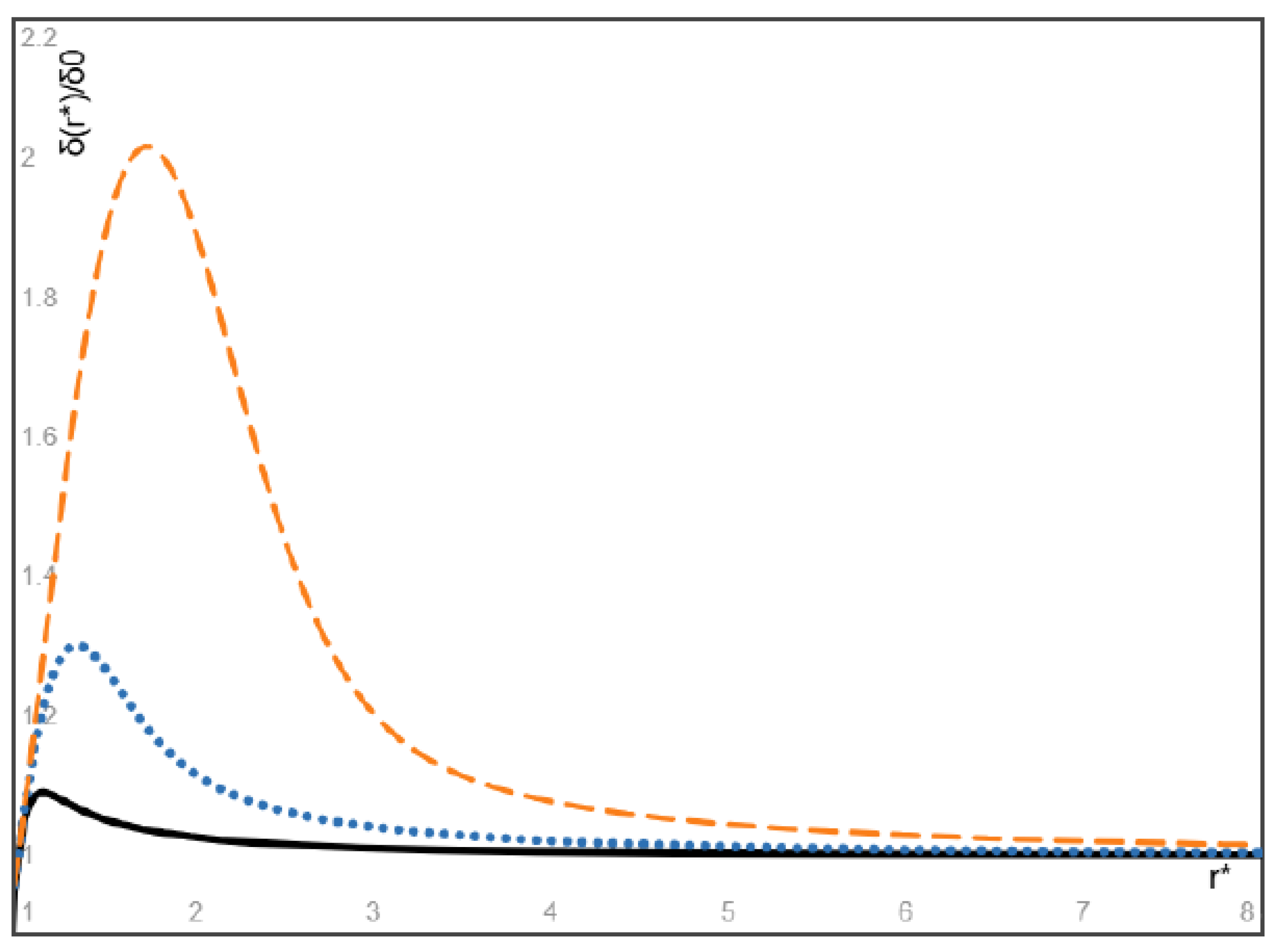
On the other hand, the dimensionless steady volume fraction of particles given by (34) is plotted in Figure 8 for massless bubbles () with three values of =1, 3 and 10, respectively. It is seen from Figure 8 that the volume fraction of massless bubbles attains its maximum at a location nearby the entrance of the flow, and after then the bubble volume fraction monotonically decreases with increasing radial coordinate and converges to a finite value. Particularly, the maximum value of the particle volume fraction and its location approach the inlet particle volume fraction δ0 and the entrance location r=r0 as the value of approaches infinity, or equivalently as the modified Stokes number of bubbles approaches zero.
To our current knowledge, the existence of the location with the minimum (or maximum) volume fraction of heavier (or lighter) particles in the steady particle distribution of a diverging radial flow has not been addressed in literature, and therefore a comparison of this interesting prediction with known data cannot be made here due to the lack of available related results in literature.
5. Conclusions
Steady spatial distribution of particles in various flow problems of particle-laden viscous or inviscid fluids is not extensively addressed in literature. The present work focuses on the diverging plane radial flow of a particle-fluid viscous or inviscid suspension when the velocity field depends on the radial coordinate solely, with particular interest in the steady spatial particle distribution attained eventually as a result of particle migration. Our main results include
- (1)
- In the initial flow field of a particle-fluid suspension with uniformly distributed particles, the relative velocity of particles with respect to the fluid depends on their inlet velocity ratio, the mass density ratio and the Stokes number of particles. For example, when their inlet velocities are equal (then Stokes drag vanishes at the entrance), the particles heavier (or lighter) than the fluid will move faster (or slower) than the fluid. On the other hand, the particles lighter than the fluid can remain faster than the fluid within a sufficiently long distance provided that the inlet velocity of lighter particles is much higher than the inlet velocity of the fluid. This result is qualitatively consistent with some known simulations and experiments on gas-liquid bubbly flow in a diverging channel of finite length driven by high-speed injection of gas bubbles into a nearly stationary liquid.
- (2)
- An explicit expression is obtained for the steady spatial distribution of particles attained eventually as a result of particle migration. In particular, for massless gas bubbles with the inlet velocity higher than the inlet velocity of the fluid, our results show that the volume fraction of bubbles attains its maximum at a location close to the entrance of the flow and after then monotonically decreases with increasing radial coordinate and converges to a finite value determined by the inlet velocity ratio of the bubbles and the fluid. In addition, the maximum volume fraction and its location approach the inlet volume fraction of the bubbles multiplied by the inlet velocity ratio and the entrance location of the flow, respectively, as the Stokes number of bubbles approaches zero.
- (3)
- When the particles and the fluid have the same inlet velocity, our results show that the particles heavier than the fluid attains its minimum at a location close to the entrance of the flow and after then monotonically increases with increasing radial coordinate and converges to a finite value, and the minimum volume fraction and its location approach the inlet particle volume fraction and the entrance location of the flow as the Stokes number of heavy particles approaches zero. On the other hand, the volume fraction of light particles attains its maximum at a location close to the entrance of the flow and after then monotonically decreases with increasing radial coordinate and converges to a finite value, and the maximum volume fraction of light particles and its location approach the inlet particle volume fraction and the entrance location of the flow as the Stokes number of light particles approaches zero
Funding
No external fund is applied for this work.
Contribution
As the sole author of this article, CQ Ru designed the research and conducted all details of this article, including literature search, all detailed derivations, and also CQ Ru wrote the first draft and final version of the manuscript, including the preparation of the figure.
Ethical approval
This article does not contain any studies with human participants or animals performed by any of the authors. The data that supports the findings of this study are available within the article.
Declaration of interests
The author has no known competing financial interests or personal relationships that could have appeared to influence the work reported in this paper.
Appendix A. Derivation of Equations (1-5)
For an incompressible Newtonian fluid with uniformly suspended identical solid spheres, the single-phase models [16,17,18] treat it as a homogeneous incompressible viscous fluid with constant effective viscosity μ and mass density ρ, governed by the classical Navier-Stokes equations (in the absence of body force)
where x and t are the spatial coordinates and time, v(x, t) is the velocity field of the particle-fluid suspension (defined as the velocity field of the geometrical center of the representative unit cell of suspension), p(x, t) is pressure field of the suspension, and are gradient and the Laplacian operators, the mass density ρ (per unit volume) of the suspension is given by
where ρs and ρf are the mass densities of the particles and the carrier fluid, respectively, δ is the volume fraction of the particles, μ is the effective viscosity of the suspension which can be estimated by Einstein formula with the viscosity μf of the carrier fluid in the dilute limit. Single-phase models cannot explain some multiphase flow phenomena of particle-laden fluids such as particle migration.
The present model addresses the decisive role of the relative shift between the velocity field vS(x, t) of dispersed particles and the velocity field vf(x, t) of carrier fluid when the particles are not neutrally buoyant (ρS≠ρf). Actually, the Newton’s second and third laws imply that the resultant external force acting on the representative unit cell, given by the terms on right-hand side of eq.(A1), equates to the mass of the unit cell multiplied by the acceleration dvm/dt of its mass center (rather than the acceleration field dv/dt of its geometrical center), and therefore, instead of eq.(A1), dv/dt on left-hand side of (A1) should be replaced by dvm/dt and the suspension is governed by the modified form of Navier-Stokes equations (1), where vm(x, t) is the velocity field of the mass center of the representative unit cell defined by the mass-averaged velocity field
where δ(x, t) can change with the spatial position and time due to particle migration, and consequently, the density ρ and the effective viscosity μ of the suspension may vary with the spatial position and time.
To derive a relationship between vm(x, t) and v(x, t), let us start with the suspension’s velocity v(x, t) given by the volume-averaged mixture rule . Thus, (A3) gives the following mass-averaged velocity field relation
And the mass-averaged acceleration field relation of (A4) gives
where d/dt denotes the material derivative of the associated velocity field along its own streamlines, and vS(x, t) can be given in terms of v(x, t) and vm(x, t) from (A4).
Considering the Stokes drag, forces due to added mass and particle acceleration and the lift force acting on a suspended sphere (of radius rS) which moves with respect to the particulate fluid of the effective viscosity μ and effective mass density ρ, we have (the gravity not involved) [23,24,25,26,27,28]
where Ca and CL are the added mass and the lift force coefficients, respectively. Dynamics of the solid sphere is governed by
Diving both sides by , the above equation is reorganized into
Multiplying () to both sides of (A8), on using (A4) and (A5) to eliminate the velocity field vS and its material derivative dvS/dt in (A8), we have the relation (4) with the coefficients a and b given by (5).
Finally, in the case of particle migration with time-varying non-uniform volume fraction δ(x, t) of particles, the conservation of mass for the carrier fluid and solid particles gives
respectively. In view of (A3) and the above volume-averaged velocity relation, (A9, A10) give equations (2, 3) in terms of v(x, t) and vm(x, t). In summary, we have eight equations (1-4) for δ(x, t), two velocity fields v(x, t) and vm(x, t) and the pressure field p(x, t).
The present model based on the Stokes drag alone has been used to study the linear stability of plane parallel flow [51] and Kelvin-Helmholtz instability of fluid interface [52], and it is showed that the results derived by the present model for heavy particles in a dusty gas are identical to the Saffman’s classical results [29] and the results of Michael [30] derived by the classical Saffman model, respectively. This offers supporting evidence for the efficiency and accuracy of the present model. In addition, for the gas bubble-liquid two-phase suspensions, the physical concepts and mathematical equations formulated in the two-fluid models [23,24,25,26,27,28] for spherical solid particles can be largely applied to bubbly fluids with dispersed spherical gas bubbles [47,48,49,50].
References
- Jeffery GB (1915) The two-dimensional steady motion of a viscous fluid. Phil. Mag. (Series 6) 29, pp455-465.
- Fraenkel LE (1962) Laminar flow in symmetrical channel with slightly curved walls. I. On the Jeffery-Hamel solutions for flow between plane walls. Proc. R. Soc. London A267, pp119-138.
- Eagles PM (1966) The stability of a family of Jeffery-Hamel solutions for diverging channel flow. J. Fluid Mech. 24(1), pp191-207.
- Fujimura K. On the linear stability of Jeffery-Hamel flow in a converging channel. J. Phys. Soc. Japan 1982, 51, 2000–2009. [Google Scholar] [CrossRef]
- Banks, WHH; et al. (1988) On perturbations to Jeffery-Hamel flow. J. Fluid Mech.186, pp559-581.
- Akulenko, LD; et al. (2004) Solutions of the Jeffery-Hamel problem regularly extendable in the Reynolds number. Fluid. Dyn. 39(1), pp12-28.
- Putkaradze V & Vorobieft P (2006) Instabilities, bifurcations, and multiple solutions in expanding channel flows. Phys. Rev. Let.(7), 144502.
- Haines, PE; et al. (2011) The Jeffery-Hamel similarity solution and its relation to flow in a diverging channel. J. Fluid Mech. 687, pp404-430.
- Jotkar MR & Govindarajan R (2017) Non-modal stability of Jeffery-Hamel flow. Phys. Fluids.29, 064107.
- Noureen & Marwat DNK (2022) Double-diffusive convection in Jeffery-Hamel flow. Sci. Reports 12, 9134.
- Goli, S; et al. (2022) Physics of fluid flow in an hourglass (converging-diverging) microchannel. Phys. Fluids 34 (5), 052006.
- Kumar A; Govindarajan R. On the intense sensitivity to wall convergence of instability in a channel. Phys. Fluids 2024, 36, 104108. [Google Scholar] [CrossRef]
- Rezaee D (2024) Linear temporal stability of Jeffery-Hamel flow of nanofluids. Euro. J. Mech./B Fluids 107, pp1-16.
- Rana, P; et al. Multiple solutions and temporal stability for ternary hybrid nanofluid flow between non-parallel plates. J. Appl. Math. Mech. (ZAMM) 2024, 104, e202400124. [Google Scholar] [CrossRef]
- AI-Saedi, AA; et al. (2025) Study on Jeffery-Hamel nano-fluid flow with uncertain volume fraction using semi-analytical approach. AIP Advances 15, 045113.
- Park, H.M. (2018) Comparison of the pseudo-single-phase continuum model and the homogeneous single-phase model of nanofluids. Int. J. Heat & Mass Transfer 120, pp106-116.
- Saha, G. & Paul M.C. (2018) Investigation of the characteristics of nanofluids flow and heat transfer in a pipe using a single phase model. Inter. Communications in Heat & Mass Transfer 93, pp48-59.
- Turkyilmazoglu M (2020) Single phase nanofluids in fluid mechanics and their hydrodynamic linear stability analysis. Computer Methods & Programs in Biomedicine 187, 105171.
- AI-Nimr, MA; et al. (2010) Effect of velocity-slip boundary conditions on Jeffery-Hamel flow solutions. J. Appl. Mech.(ASME) 77, 041010.
- Turkyilmazoglu M (2014) Extending the traditional Jeffery-Hamel flow to stretchable convergent/divergent channel. Computer & Fluids 100, pp196-203.
- Soliman HM (2017) Laminar, radial flow of two immiscible fluids in slender wedge-shaped passages. J. Fluids Engng. (ASME) 139, 081201.
- Sahu KC & Govindarajan R (2005) Stability of flow through a slowly diverging pipe. J. Fluid Mech. 531, pp325-334.
- Klinkenberg, J.; et al. (2014) Linear stability of particle laden flows: the influence of added mass, fluid acceleration and Basset history force. Mechanica 49, pp811-827.
- Ru CQ (2024) Rotational flow field of a particle-laden fluid on a co-rotating disk. Phys. Fluids (36) (11), 113356.
- Rubinow SI & Keller JB (1961) The transverse force on a spinning sphere moving in a viscous fluid. J. Fluid Mech.11, pp447-459.
- Saffman PG (1965) The lift on a small sphere in a slow shear flow. J. Fluid Mech.22, pp385-400.
- Boronin SA & Osiptsov AN (2020) Stability of a vertical Couette flow in the presence of settling particles. Phys. Fluids (32), 024104.
- Li, H; et al. (2020) Eulerian-Lagrangian simulation of inertial migration of particles in circular Couette flow. Phys. Fluids ((32), 073308.
- Saffman, P.G. (1962) On the stability of laminar flow of a dusty gas. J. Fluid Mech.13, pp120-128.
- Michael DH (1965) Kelvin-Helmholtz instability of a dusty gas. Proc. Camb. Phil. Soc.61, pp569-571.
- Yang, Y; et al. (1990) The influence of particles on the spatial stability of two-phase mixing layers. Phys. Fluids A2 (10), pp1839-45.
- Dimas AA & Kiger KT (1998) Linear instability of a particle-laden mixing layer with dynamic dispersed phase. Phys. Fluids (10), pp253957.
- Senatore, G; et al. (2015) The effect of non-uniform mass loading on the linear, temporal development of particle-laden shear layers. Phys. Fluids 27, 033302.
- Goldshtik MA & Shtern VN (1989) Loss of symmetry in viscous flow from a linear source. Fluid Dyn. 24, pp151-199.
- Shusser M & Weihs D (1995) Stability analysis of source and sink flows. Phys. Fluids 7(10), pp245-2353.
- Putkaradze V & Dimon P (2000) Non-uniform two-dimensional fluid from a point source. Phys. Fluids 12(1), pp66-70.
- Chemetov NV & Starovoitov VN (2002) On a motion of a perfect fluid in a domain with sources and sinks. J. Math. Fluid Mech.4, pp128-144.
- Taylor GI (1932) The viscosity of a fluid containing small drops of another fluid. Proc. R. Soc. Lond. A138, pp41-48.
- Ohie, K; et al. (2024) Rheology of dilute bubble suspension in unsteady shear flow. J. Fluid Mech. (983), A39.
- Auton, TR; et al. (1988) The forces exerted on body in inviscid unsteady non-uniform rotational flow. J. Fluid Mech.197, pp241-257.
- Kuo JT & Wallis GB (1988) Flow of bubbles through nozzles. Int. J. Multiphase Flow (14) (5), pp547-564.
- Chen, J; et al. (2024) Numerical simulation of single bubble motion fragmentation mechanism in Venturi-type bubble generator. Mechanics & Industry (25), 21.
- Zhao, L; et al. (2024) Investigations on the near-wall bubble dynamic behaviors in a diverging channel. AIP Advances 14, 115014.
- Zeng, X; et al. (2025) Simulation of the vane-type bubble separator using a hybrid Euler-Euler/volume-of-fluid approach. Phys. Fluids (37), 043330.
- Tribbiani, G; et al. (2025) An image-based technique for measuring velocity and shape of air bubbles in two-phase vertical bubbly flows. Fluids (10), 69.
- Nedeltchev S (2025) Updated review on the available methods for measurement and prediction of the mass reansfer coefficients in bubble columns. Fluids (10), 29.
- Magnaudet J & Eames I (2000) The motion of high-Reynolds-Number bubbles. Annu. Rev. Fluid Mech. (32), pp659-708.
- Khan, I; et al. (2020) Two-phase bubbly flow simulation using CFD method: a review of models for interfacial forces. Prog. Nuclear Energy (125), 103360.
- Basagni, G; et al. (2023) Computational fluid dynamics modeling of two-phase bubble column: a comprehensive review. Fluids (8), 91.
- Legendre D & Zenit R (2025) Gas bubble dynamics. Rev. Modern Phys. (97), 025001.
- Ru CQ. Stability of plane parallel flow revisited for particle-fluid suspensions. J. Appl, Mech. (ASME) 2024, ((91)), 111005. [Google Scholar]
- Ru CQ (2025) On Kelvin-Helmholtz instability of particulate two-fluid flow. Acta Mechanica Sinica (41), 324143.
Figure 1.
Plane decelerating radial flow of a particle-laden fluid with the r-dependent velocity field.
Figure 1.
Plane decelerating radial flow of a particle-laden fluid with the r-dependent velocity field.
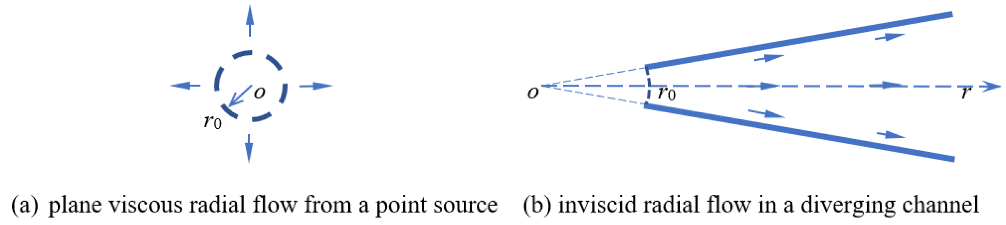
Figure 2.
The velocity difference ((uS-uf)/u) between the massless bubbles and the fluid given by (22) with the inlet velocity ratio u0S=2u0f, where uS , uf and u are the velocities of the bubbles, the fluid and the suspension, respectively, for three larger values of the bubble Stokes number presented by =1 (solid black), 0.1 (dotted blue), and 0.01 (dashed orange), respectively.
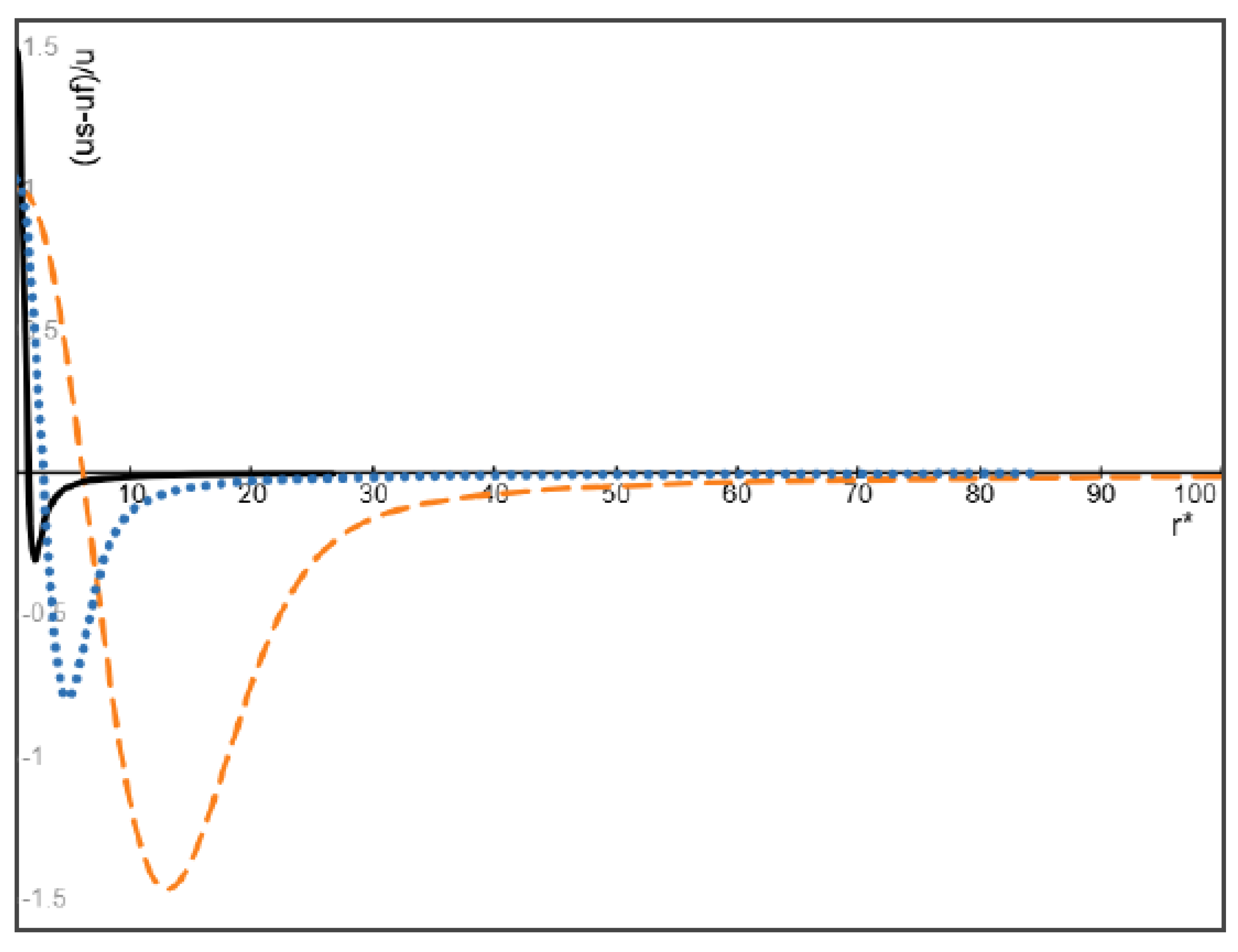
Figure 3.
The velocity difference ((uS-uf)/u) between the massless bubbles and the fluid given by (22) with the inlet velocity ratio u0S=10u0f, for three larger values of the bubble Stokes number presented by =1 (solid black), 0.1 (dotted blue), and 0.01 (dashed orange), respectively.
Figure 3.
The velocity difference ((uS-uf)/u) between the massless bubbles and the fluid given by (22) with the inlet velocity ratio u0S=10u0f, for three larger values of the bubble Stokes number presented by =1 (solid black), 0.1 (dotted blue), and 0.01 (dashed orange), respectively.
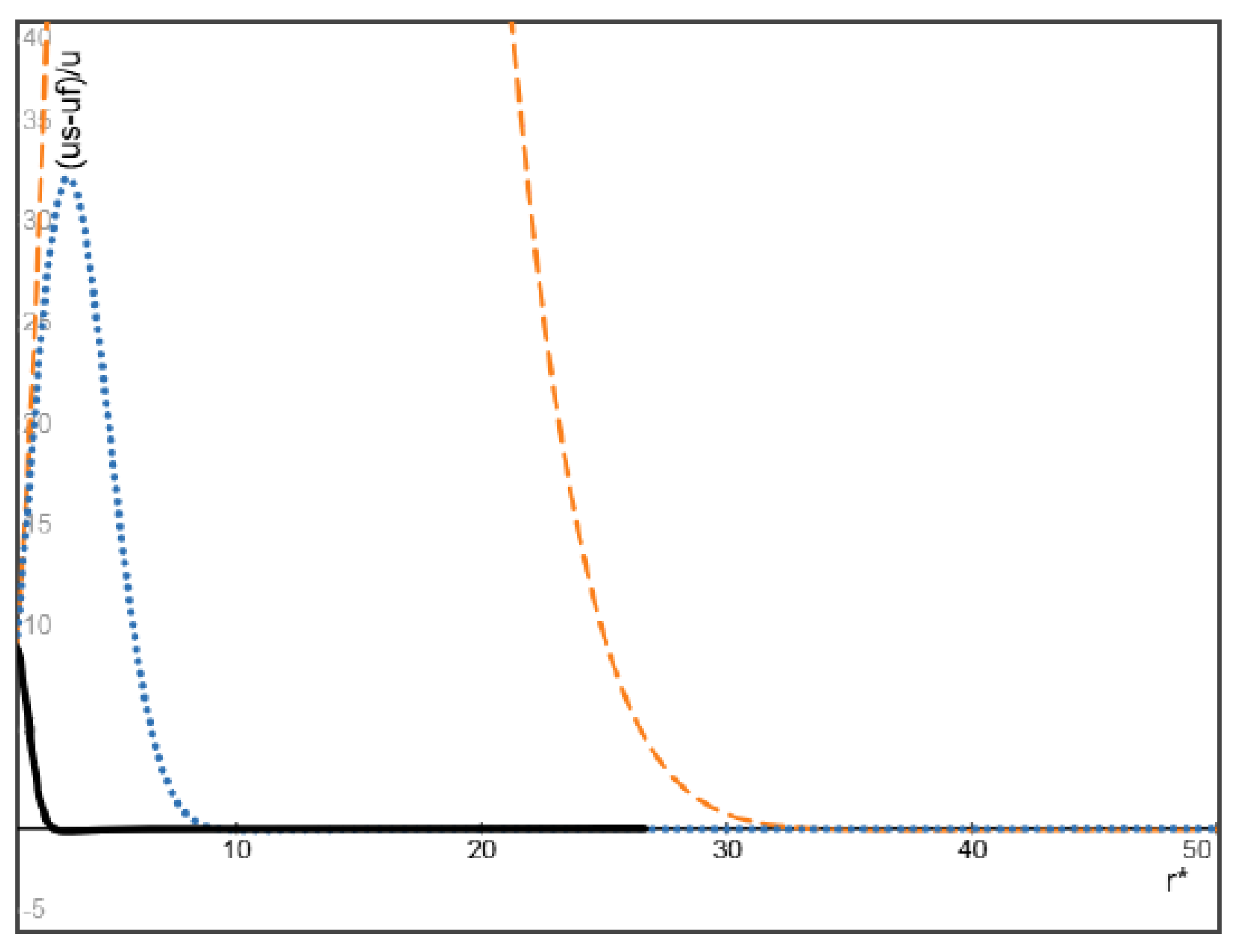
Figure 4.
The function Ω(r*) defined by (24) for the velocity difference ((uS-uf)/u), for the three values of =1 (dotted blue), 3 (dashed orange), and 10 (solid black), respectively.
Figure 4.
The function Ω(r*) defined by (24) for the velocity difference ((uS-uf)/u), for the three values of =1 (dotted blue), 3 (dashed orange), and 10 (solid black), respectively.
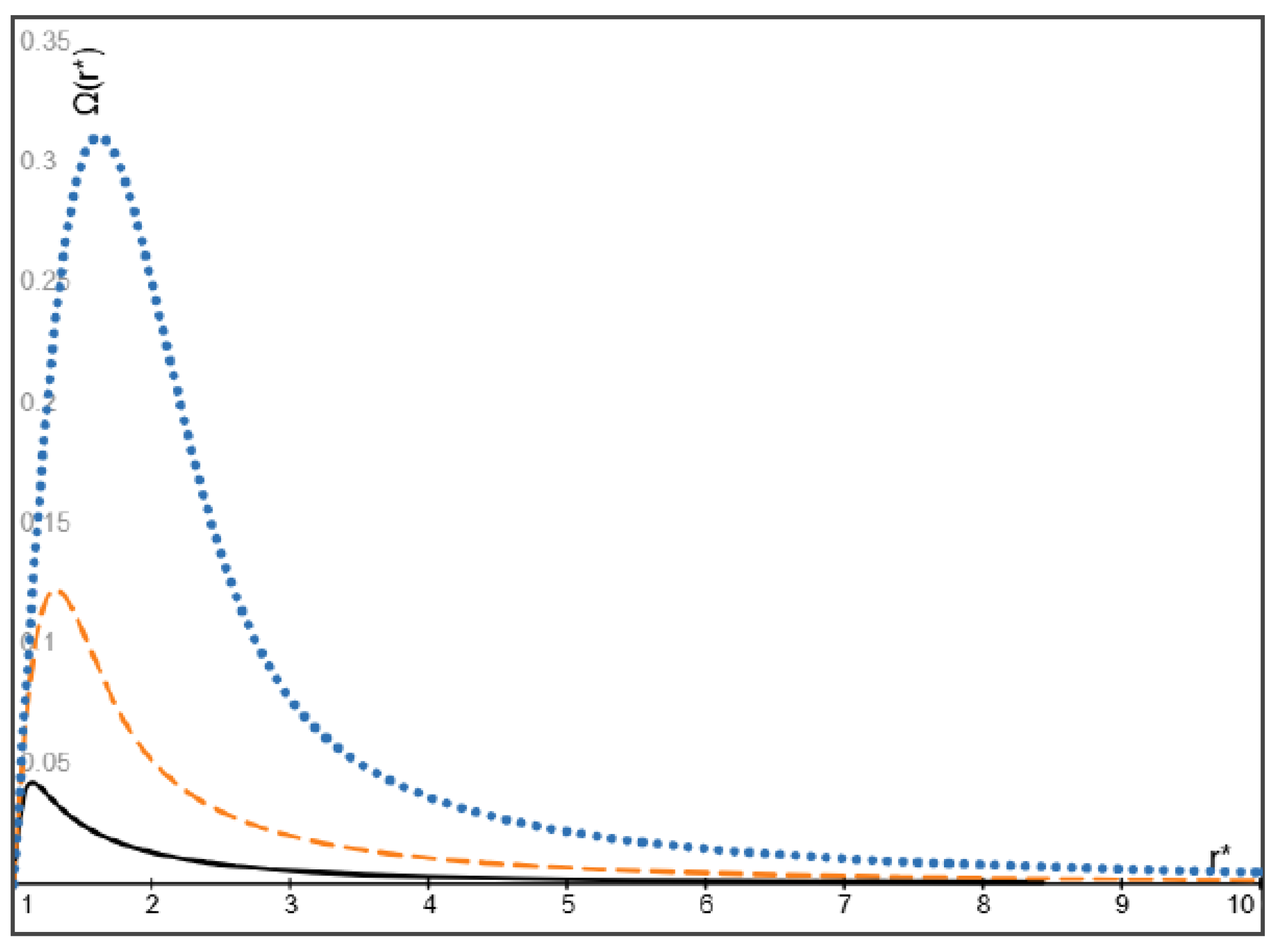
Figure 5.
The dimensionless steady bubble volume fraction given by (33) with u0S=2u0f, for the three values of =10 (solid black), 3 (dotted blue), and 1 (dashed orange), respectively.
Figure 5.
The dimensionless steady bubble volume fraction given by (33) with u0S=2u0f, for the three values of =10 (solid black), 3 (dotted blue), and 1 (dashed orange), respectively.
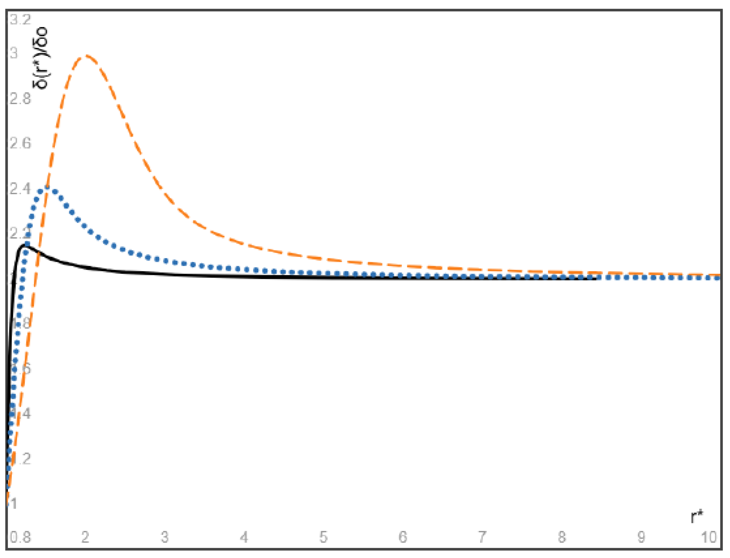
Figure 6.
The dimensionless steady bubble volume fraction given by (33) with u0S=10u0f, for the three values of =10 (dashed orange), 3 (dotted blue), and 1 (solid black), respectively.
Figure 6.
The dimensionless steady bubble volume fraction given by (33) with u0S=10u0f, for the three values of =10 (dashed orange), 3 (dotted blue), and 1 (solid black), respectively.
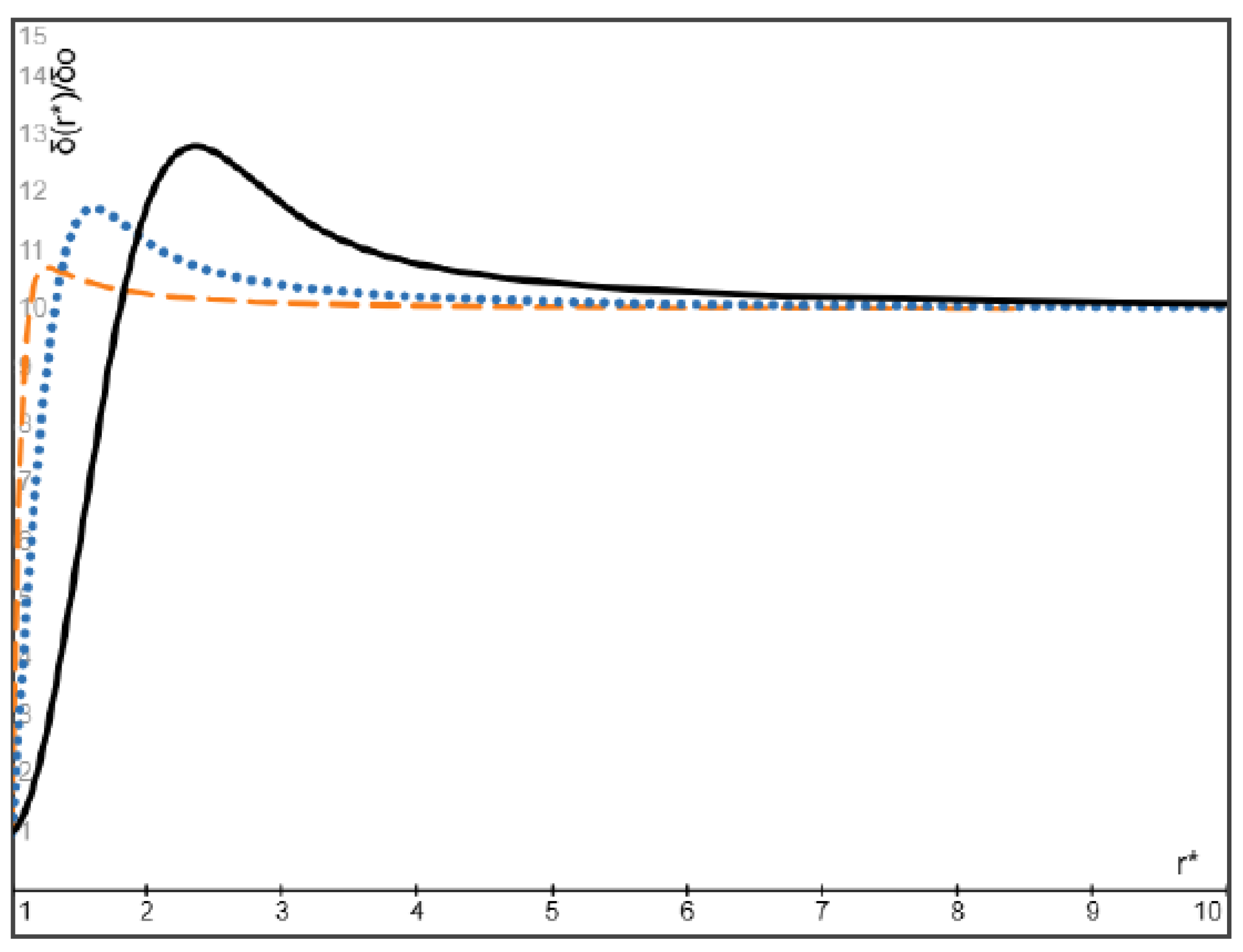
Figure 7.
The dimensionless steady volume fraction of heavy particles given by (34) with the same inlet velocity of particles and fluid (u0S=u0f), for the three values of =10 (solid black), 3 (dotted blue), and 1 (dashed orange), respectively.
Figure 7.
The dimensionless steady volume fraction of heavy particles given by (34) with the same inlet velocity of particles and fluid (u0S=u0f), for the three values of =10 (solid black), 3 (dotted blue), and 1 (dashed orange), respectively.
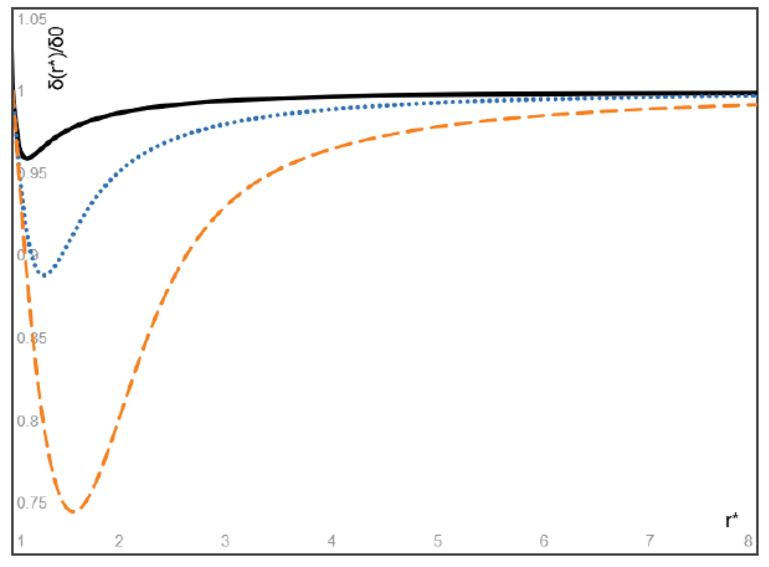
Figure 8.
The dimensionless steady volume fraction of massless bubbles (ρS<<ρf) given by (34) with the same inlet velocity of bubbles and fluid (u0S=u0f), for the three values of =10 (solid black), 3 (dotted blue), and 1 (dashed orange), respectively.
Figure 8.
The dimensionless steady volume fraction of massless bubbles (ρS<<ρf) given by (34) with the same inlet velocity of bubbles and fluid (u0S=u0f), for the three values of =10 (solid black), 3 (dotted blue), and 1 (dashed orange), respectively.
Disclaimer/Publisher’s Note: The statements, opinions and data contained in all publications are solely those of the individual author(s) and contributor(s) and not of MDPI and/or the editor(s). MDPI and/or the editor(s) disclaim responsibility for any injury to people or property resulting from any ideas, methods, instructions or products referred to in the content. |
© 2025 by the authors. Licensee MDPI, Basel, Switzerland. This article is an open access article distributed under the terms and conditions of the Creative Commons Attribution (CC BY) license (http://creativecommons.org/licenses/by/4.0/).
Copyright: This open access article is published under a Creative Commons CC BY 4.0 license, which permit the free download, distribution, and reuse, provided that the author and preprint are cited in any reuse.


