Submitted:
27 June 2025
Posted:
27 June 2025
You are already at the latest version
Abstract
Inorganic electrolytes are commonly used in commercial electropolishing. However, interest in eco-friendly electrolytes is on the rise. This investigation presented how electropolishing with choline chloride, an eco-friendly electrolyte, affects the molar ratio of ethylene glycol and applied potential. Electrochemical experiments were conducted in natural seawater on stainless steel electropolished under ideal conditions. The passive current density increased as the ethylene glycol molar ratio rose (1:1, 1:2, 1:3) in choline chloride. However, the plateau of the passive current density was most clearly observable in a solution composed of choline chloride and ethylene glycol at a 1:2 molar ratio. Electropolishing under optimal conditions reduced the surface roughness and height by 67.3% and 90.5%, respectively, compared to mechanical polishing. The corrosion current density of the mechanically polished and electropolished stainless steel was calculated as 0.35 ㎂/cm2 and 0.01 ㎂/cm2, respectively, and the pitting potential was 286.08 mV and 410.11 mV, respectively.
Keywords:
Stainless steel
; eco-friendly electrolyte
; Electropolishing
; Sea water
; Anti-corrosion
1. Introduction
Among the varieties of stainless steel, UNS S31603 has excellent corrosion resistance because it forms a passive film in a corrosive environment. Therefore, it is widely used in high-value-added industries, such as the shipbuilding, marine industries, petroleum, chemical plants, biomedicine and food companies [1]. Generally, the stainless steel used in industrial fields has a rough surface because it is mechanically polished [2]. Accordingly, problems with mechanically polished stainless steel include the formation of fine grooves, creation of a corrosive environment (potential difference due to impurities) and development of fatigue due to stress concentration [3]. In particular, passive films on surfaces containing impurities are prone to local corrosion in marine environments. Stainless steel used in marine environments often undergoes additional surface treatment after mechanical polishing to prevent such problems.
Common surface treatments for stainless steel include acid pickling, passivation and electropolishing, which improves corrosion resistance using inorganic nitric acid [2]. Corrosion resistance can be improved by changing the chemical composition, microstructure, and thickness of the passive film. However, the research using eco-friendly electrolytes is currently underway due to the disadvantages of surface treatments that use acid, such as environmental issues, handling risks, environmental corrosion, low current efficiency and extensive gas generation [4]. In particular, among the various surface treatments, electropolishing has various advantages, such as improved corrosion resistance, a gloss-formation effect, surface cleanliness due to the removal of fine burrs, reduction of bacterial growth and removal of surface stress and deformation [5]. Accordingly, the electropolishing has been applied to automobile parts, pharmaceuticals, medical care (surgical instruments, dental instruments, needles, implants, etc.), semiconductors, and more [6].
W. Han et al. electropolished UNS S31603 using an NaCl-based, eco-friendly electrolyte [2]. C. Rotty et al. compared and analyzed the effects on UNS S31603 of different manufacturing methods after electropolishing with an eco-friendly electrolyte based on ChCl (choline chloride) [7]. A. Kityk et al. compared the electrochemical characteristics of manganese stainless steel after electropolishing with a deep eutectic solvent (eco-friendly electrolyte) [8]. According to H. K. Hwang et al., among the various factors that determine the outcome of electropolishing (electrolyte composition ratio, processing time, applied current density or potential, temperature, etc.), the electrolyte composition ratio has the most significant effect [9]. Although various eco-friendly electrolytes have thus been investigated, no articles have examined the composition ratio of eco-friendly electrolytes.
Therefore, based on the work of C. Rotty et al. and A. Kityk et al. [7,8], the eco-friendly electrolyte selected for use in this investigation was a mix of choline chloride and ethylene glycol, which has the best electropolishing effect among deep eutectic solvents. The effects of electropolishing using this substance were evaluated in relation to changes in the molar ratio of ethylene glycol and applied potential (as determined by the passive current density)
2. Experimental Method
2.1. Specimen
In this research, austenitic stainless steel, UNS S31603 was used. Its chemical composition is 16.70 wt.% Cr, 0.012 wt.% N, 2.03 wt.% Mo, 10.19 wt.% Ni, 0.023 wt.% C, 0.60 wt.% Si, 1.05 wt.% Mn, 0.034 wt.% P, and 0.282 wt.% Cu; the balance is Fe. In general, the method used to evaluate the pitting resistance of stainless steel is based on the pitting resistance equivalent number (PREN), and the calculation formula is as follows [10].
PREN = %Cr + 3.3(%Mo+0.5%W) + 16%N
The PERN of the stainless steel used in this examination was 23.6. This indicates resistance to pitting and crevice corrosion in chloride-filled environments, such as seawater. In standard specifications for oil and gas, which can cause enormous damage to life and the environment due to corrosion in the marine environment, the stainless steel must have a PERN of 40 or higher [11]. However, the material used in this investigation was stainless steel, which is commonly used in the marine industry and is applied to various targets, such as offshore plants and marine structures [12]. The specimen was processed while minimizing thermal deformation using a fine-cutting machine supplied with coolant. The processed specimen was mounted with epoxy resin so that 4 cm2 was exposed. The mounted specimen was mechanically polished step by step up to emery paper #220. Afterwards, it was ultrasonically cleaned with acetone and distilled water, completely dried in a dryer for 24 hours, and then subjected to electropolishing.
2.2. Electropolishing
2.2.1. Electrolyte composition ratio
The electropolishing solution used was ethylene along with a deep eutectic solvent (DES)—i.e., an eco-friendly electrolyte—and it was produced by mixing choline chloride and ethylene glycol. The molar ratio of choline chloride and ethylene glycol [C2H6O2 (structural formula: HO(CH2)2OH)] used is shown in Table 1. The electropolishing solution was mixed at 70°C for 1 hour until it became completely colorless.
2.2.2. Electrochemical experiment
The electrochemical experiment used a 3-electrode cell, and a silver/silver chloride (Ag/AgCl-saturated, 3.3-M KCl) electrode and platinum mesh electrode were used as the reference and counter electrodes, respectively. First, as a preliminary investigation of the electropolishing conditions, the electrochemical characteristics were analyzed in ethylene through potentiodynamic polarization experiments on stainless steel. In this experiment, the applied potential was from 0 to 4.5 V (vs. open-circuit potential) after an initial delay time of 30 minutes at 70°C. The electropolishing was conducted using potentiostatic polarization experiments, which provide potential standards.
The electrochemical characteristics were compared and analyzed by performing potentiodynamic polarization experiments and potentiostatic polarization experiments in seawater before and after electropolishing. Table 2 presents the components and characteristics of the natural seawater. The potentiodynamic polarization experiments were performed at a scanning rate of 1 mV/s from –0.25 to 0.65 V based on the open-circuit potential after an initial delay of 30 minutes at 40°C. In addition, electrochemistry impedance spectroscopy experiments were performed at a frequency of 100 kHz to 0.01 Hz and an amplitude of 10 mV.
2.2.3. Specimen surface analysis
The specimen’s phase and surface characteristics before and after electropolishing were analyzed using an X-ray diffractometer (XRD). The 2θ range was 30o to 80o, respectively, with a step size of 0.02o and a scan time of 1.0 sec/step under the Cu Kα condition of λ = 1.546 Å. The phase was analyzed by comparing the obtained XRD data and ICDD data files. The electropolished surface was evaluated using a 3D laser microscope and a scanning electron microscope. In addition, surface observations to determine corrosion resistance were conducted using 3D laser microscopy, field emission scanning electron microscopy, and energy dispersive spectroscopy (EDS).
3. Experimental Results and Considerations
3.1. Surface treatment and analysis
Figure 1 presents the results of a surface analysis of mechanically polished stainless steel conducted using a scanning electron microscope (a) and a 3D profile of the sample (b). The surface was rough, and many fine burrs and defects were observable. The surface roughness and the height difference between the mountains and valleys were calculated as 0.614㎛ and 6.13㎛, respectively.
Figure 2 presents the results of the potentiodynamic polarization experiment in the eco-friendly electrolyte (choline chloride: ethylene glycol = 1:1). In order to magnify and examine each area, the X-axis range was reduced to 0.02–0.04 A/cm2.
The characteristics relevant to electropolishing in each area are as follows [13]. Area 1 is an active dissolution reaction area where corrosion damage occurs. Area 2 is a passive region, and the current density is slightly lower. This is because a passive oxide film is formed on the surface of the specimen used as the anode. Area 3 is a section in which the passive film remains stable and displays a low current density. Area 4 is a transpassive section in which the current density increases rapidly as the potential increases. In this area, corrosion occurs due to the destruction of the passive film, and oxygen is generated during the dissolution process.
Electropolishing should be carried out in the potential region where the passive film remains stable, and the surface tends to become flatter at high potentials within the passive current density [14]. Based on this, a potentiodynamic polarization experiment with the molar ratio of ethylene glycol was conducted to investigate the effect of the ethylene glycol on electropolishing outcomes.
Figure 3 shows the results of the potentiodynamic polarization experiment with the ethylene glycol molar ratio at 70℃. The open-circuit potential was similar in all mixing conditions, at about –0.27 V. However, the molar concentration of the ethylene glycol exhibited differences in the passive current density value, current density plateau period (②–④), pitting, and oxygen generation potential. The passive current density value increased with a higher ethylene glycol molar concentration. When the ethylene glycol molar ratio was 2, the passive plateau period was at its longest and the pitting potential at its highest. The passive current density value and stability period represent the characteristics of the passive film. From a corrosion perspective, given the same potential, a larger passive current density value corresponds to a less stable passive film, resulting in lower corrosion resistance [15]. However, from the perspective of electropolishing, the larger the passive current density value, the faster the uneven surface can be dissolved, and the faster the process can be completed [7]. Grimm et al. reported that electropolishing is performed through a mechanism facilitated by a duplex salt film created on the metal’s surface [16]. The salt film is created by the reaction between cations (Fe2+, Cr3+, Mo3+, etc.) in the substrate and anions (OH-) in the solution. It is believed that as the concentration of ethylene glycol increases, the number of anion particles also increases, thereby promoting a dissolution reaction in the cations to create a salt film. As a result, it is thought that the increase in the passive current density values promotes the dissolution reaction in the cations due to the increased ethylene glycol concentration.
The plateau period of the current density is reached when the chemical reaction forming the salt film is saturated (suppressing the cation dissolution reaction of the substrate), and this is because a small number of cations and anions are stably diffused into the electrolyte [16]. Electropolishing removes protrusions, so stable diffusion is required, and the dissolution reaction of the substrate must be suppressed as much as possible. For this reason, electropolishing is performed in a passive (current density stable) period [17]. The longer the plateau period of the current density, the more stable the salt film, and the better the conditions for controlling diffusion. It is supposed that the stability of this salt film affects the pitting and oxygen generation potential. Therefore, in the case of 2 moles of ethylene glycol, the stability of the salt film is judged to be the best because the current density’s plateau period is the longest.
To investigate the effect of electropolishing on the stability of a salt film, electropolishing was performed at 70°C for 20 minutes with potential conditions ①–⑤, which were calculated based on of the potentiodynamic polarization experiment displayed in Figure 3.
Figure 4 displays the current density over the electropolishing time and the surface after electropolishing. The same current density pattern in the applied potential was observed in all electrolyte conditions. In the two lowest potential conditions (①, ②), the current density over time initially increased rapidly and then exhibited a stable value as it decreased. In the case of the intermediate potential condition (③), the current density initially decreased rapidly and then remained constant. The current density in the two highest potential conditions (④ and ⑤) decreased sharply and then exhibited a constant value as it increased.
For the second-lowest potential condition among all the electrolyte conditions, gloss was observed only at 1 mole of ethylene glycol. Afterwards, under conditions above the intermediate potential, all electrolytes exhibited gloss.
However, under the two highest potential conditions (④, ⑤), both damage and gloss were observed. Differences were observed in the current density value and surface conditions maintained during the potentiostatic polarization experiment at potential ②–④ within the passive section. This difference was due to the passive film on the metal’s surface [18]. The higher the potential, the more electromagnetic fields formed in the passive film [18]. This electromagnetic field affects the chemical structure coordination number of the passive film and the distance between atoms in the metal. A slight change in the coordination number affects the diffusion rate of ions and oxygen, thereby changing the thickness of the passive film. It was believed that differences in current density and surface condition emerged because the surface resistance characteristics were different due to the various passive film thicknesses.
Figure 5 displays an image and the height difference between the mountains and valleys using a 3D laser microscope after electropolishing with the applied potential. In all electrolyte conditions, the height difference between the mountains and valleys was observed to follow the same pattern: increasing after decreasing as the potential increased. For all electrolytes, under potential condition ①, grain boundaries were distinguished (2D image) on the surface, looking like products of etching. Accordingly, other researchers have identified the active dissolution reaction region as the etching region in electropolishing [19,20]. The mountains and valleys on the surface (3D image, profile) clearly exhibited a difference in height due to this damage (etching). Afterwards, the height difference between the mountains and valleys decreased until ③. It is believed that the current density in the dissolution reaction had a dominant effect on the mountain sites, decreasing their height. This is because the current density is inversely proportional to the diffusion layer’s thickness, in accordance with Equation (2) [21].
(i: current density, Do: exponentail pre-factor, n : molar of the total charge on ion, F : Faraday constant, C : saturation concentration of metal in the solution, δ: thickness of anodic diffusion layer, Qa : activation energy for diffusion, R: gas constant, T: the absolute temperature.)
It is supposed that the diffusion layer of mountains was relatively thin compared to that of valleys, creating a high current density and thereby promoting a dissolution reaction in the mountains. From ③ to ⑤, the height difference between the mountains and valleys increased. This is thought to be a result of surface damage before and after the pitting potential. Comprehensively comparing ① to ② for all electrolyte conditions, the applied potential was similar, but the damage degree became more evident as the concentration of ethylene glycol increased. It is thought that the increase in ethylene glycol concentration increased the current density (Figure 3) in the active area, thereby increasing the damage. In the case of ③, within 2 moles and under all electrolyte conditions, the height difference between the mountains and valleys is the smallest. Accordingly, the surface electropolished under the 1-mole condition was less polished, but under the 3-mole condition, it is believed that the height difference between the mountains and valleys increased due to surface damage. Similarly, when conducted at potential ④ under all electrolyte conditions, it is thought that the electropolishing created a relative excess of energy, resulting in an increase compared to case ③.
Figure 6 presents the results of surface observations conducted after electropolishing relative to the applied potential and the surface roughness (Ra) of the profile in Figure 5. The behavior of the applied potential in 1 mole of ethylene glycol was as follows. In the case of condition ①, the metal surface was damaged by a dissolution reaction, and relatively high roughness was observed. Accordingly, grain boundary boundaries were observed. In condition ②, the grain boundary grooves decreased, and the surface became flat, reducing the roughness [22]. In conditions ③ and ④, the surface was smooth, and no change in roughness was clearly observed. However, in the case of condition ⑤, the roughness actually increased as a hemispherical pit occurred.
In the case of 2-mole and 3-mole ethylene glycol, the damage pattern of the applied potential exhibited a similar trend. When electropolishing at the lowest potential (①), pitting damage and intergranular corrosion were observed [22]. In condition ②, only grain boundary damage was observed. This is thought to be because the viscous layer that controls the dissolution rate of mountains and valleys does not form densely at potentials below average in the passive region [23]. The surface at ③ was flat, with no obvious damage. Additionally, although no clear difference was observed in the surface shape under condition ④ compared to ③, the surface roughness decreased. The electropolishing process suppresses changes in crystallographic orientation due to the microsmoothing mechanism, so it is believed that the surface microstructure would change as well [24]. T. Hryniewicz et al. reported that in the case of electropolishing performed at pitting and oxygen generation potentials, oxygen molecules adsorbed by a high magnetic field formed a denser hydroxide layer on the metal surface [25].
Figure 7 compares the height difference between the mountains and valleys (a) and the surface roughness (b) after electropolishing. The height difference and surface roughness were compared to select the optimal conditions among those tested in this investigation (i.e., in the comparison of corrosion resistance before and after electropolishing). Conditions ③ and ④ of the 2 moles were excellent height difference and surface roughness values.
Because surface roughness was evaluated based on the central area of each specimen, the roughness under ④ was calculated as lower than that under ③. However, when comparing the appearances of the stainless steel (Figure 4), some damage was observed at the edge of the specimen in ④. Therefore, the optimal condition for electropolishing was determined as condition ③ in this research. The detailed conditions for this setup are displayed in Table 3.
Figure 8 indicates the XRD analysis results after mechanical polishing and electropolishing. In general, the size of the diffraction peak is determined by the orientation of the crystal structure. Since the diffraction peak value increased after electropolishing, it is believed that the crystal orientation changed due to microsmoothing—a mechanism involved in electropolishing—as indicated in Figure 6. In addition, after the electropolishing, the diffraction peak value of the (111) (200) (220) crystal plane was crystallographically uniform. This means that the surface was flattened because a surface dissolution reaction occurred during electropolishing, which was the cause of the gloss effect. An α’martensite diffraction peak corresponding to 44.6° was observed on plane (111) during the mechanical polishing, but it was removed after electropolishing. In the case of UNS S31603, which has a relatively low nickel content, phases other than austenite may exist [26]. It is believed that the metastable austenite phase transformed into other phases due to changes in microstructure during the manufacturing process and mechanical polishing [27,28]. Therefore, as the deformed microstructure was removed during electropolishing, the austenite phase became clear and the diffraction peak value increased.
3.2. Electrochemical experiment
Figure 9 presents the potentiodynamic polarization curve in seawater at 40°C after mechanical polishing and electropolishing. The corrosion potential (Ecorr.) and corrosion current density (Icorr.) of the mechanically polished stainless steel were calculated as –225.83 mV and 0.35㎂/cm2, respectively. The corrosion potential and corrosion current density of the electropolished stainless steel were recorded as –58.15 mV and 0.01㎂/cm2, respectively. After electropolishing, the corrosion potential increased by 74.25%, and the corrosion current density decreased by 97.14%. The corrosion potential refers to the time at which corrosion begins; the corrosion potential after electropolishing indicated a nobler value, so it can be concluded that the initial corrosion was delayed [29]. Corrosion current density refers to the corrosion rate of the same material under Faraday’s law [Equation (3)] [30].
(E.W: Equivalent weight)
Accordingly, it is believed that the corrosion rate was reduced by 97.14% after electropolishing. In addition, the polarization resistance calculated using Equation (4), which implements the Tafel slope and corrosion current density, were 96.36 kΩcm2 and 2153.97 kΩcm2 for mechanical polishing and electropolishing, respectively [31].
Polarization resistance refers to resistance to oxidation reactions. After electropolishing, the polarization resistance increased by about 2,100%. The pitting potential, which indicates pitting resistance, was calculated as 286.08 mV and 410.11 mV before and after electropolishing, respectively, and the pitting resistance also improved significantly. In general, damage to metals with passive characteristics starts at foreign matters and defects in the passive film. After electropolishing, corrosion resistance and pitting resistance are improved, so the surface is very clean, and the passive film is strong, with few defects [32]. Potentiostatic polarization experiments were performed to investigate the pitting growth and behavior in seawater before and after electropolishing.
Figure 10 presents the results of the potentiostatic polarization experiment and the visual observation. In the case of mechanical polishing, the current density initially decreased rapidly and then increased steeply for 100 seconds. The current density gradually increased from 100 to 600 seconds and was maintained at 12.86 mA/cm2 until the end of the experiment. In the case of electropolishing, the current density decreased for 175 seconds, gradually increased for 300 seconds, and then increased rapidly for 450 seconds. Afterwards, the current density gradually increased, and the experiment ended at 6.35 mA/cm2. The reason for the increase in current density is thought to be the growth of stable pitting due to the destruction of the passive film. In particular, for mechanical polishing and electropolishing, the stable growth in pitting (blue arrows) was determined as 11 seconds and 175 seconds, respectively, and it can be seen that electropolishing delayed the pitting growth. Additionally, the pitting growth was suppressed during the electropolishing because the current density was lower than that in the mechanical polishing. Localized corrosion was observed in the center and edges of the mechanically polished stainless steel. However, damage to the electropolished stainless steel occurred only at the edges. M. Momeni et al. determined that the number and size of metastable pits is based on the current density before stable pitting growth [32]. Corresponding to the results of other research in this field, in this electropolishing experiment, the current density before the stable pitting growth was lower than that resulting from mechanical polishing, which explains the number and size of metastable pitting pits.
Figure 11 exhibits a 3D profile of the results of the potentiostatic polarization experiment. The width and depth of the damage to the center area and crevice resulting from mechanical polishing were 334.40㎛ / 112.66㎛ and 301.74㎛ / 117.10㎛, respectively. In the case of electropolishing, the corresponding values were 34.96㎛ / 43.31㎛ and 251.60㎛ / 116.10㎛, respectively. Thus, after electropolishing, the width and depth of damage in the center area were significantly reduced, and the damage width in the crevice area was reduced by 50.14 ㎛; however, there was no significant difference in the depth of the damage.
Figure 12 displays the results of the scanning electron microscopy that followed the potentiostatic potential polarization experiment. In the center area, the pitting from mechanical polishing was divided into areas ⓐ and ⓑ. Damage in the depth direction was observed in the pitting in ⓐ due to the self-propagation process caused by chloride ions. Chlorine ions have a high absolute value of Gibbs energy, so it is easy for them to hydrate the passive film, and their particle size is small, so they easily penetrate the passive film and cause surface damage [33]. Due to this damage, the grain boundaries of austenite microstructure were observed. An enlarged photo of the pitting edge can be seen in ⓑ, where the damage (marked in a square) takes the shape of a lace. This shape indicates the risk that localized corrosion presents as like pitting and undercuts [34]. The pitting from electropolishing was smaller than that caused by mechanical polishing, but the shape was similar. Therefore, it was proposed that the damage mechanisms of electropolishing and mechanical polishing are similar.
The results observed in the crevice area, which is the edge in mechanical polishing, are as follows [35]. The hatched area represents the solution, and the arrow indicates the direction of crevice-corrosion expansion. In area ⓐ, it was difficult to be initially ion exchange with the external solution, so crevice corrosion began. Afterwards, the critical size for crevice corrosion was exceeded, and ion exchange with the outside became easy, so the pitting grew in the depth direction, and a relatively smooth surface was observed. The surface of area ⓑ looks like a step morphology, indicating that crevice corrosion has expanded. Area ⓒ is the opposite region with the hatched area. Where metastable pitting is clearly observed, it indicates the possibility of expanding crevice corrosion. In particular, when the critical size for crevice corrosion is exceeded, metastable pitting is not observed, and crevice corrosion no longer extends in the width direction. During the mechanical polishing within same time, most of the expansion of the crevice corrosion occurred, and only a slight amount of metastable pitting was observed. However, in the electropolishing, the crevice corrosion was less extensive, and the metastable pitting was clearly expressed. Therefore, the crevice corrosion process in the case of electropolishing was suppressed. In this investigation, the chemical composition of inside the damaged and other areas was analyzed to determine the cause of the delay in pitting after the electropolishing.
Figure 13 indicates the results of an EDS analysis the damaged parts and other areas after potentiostatic polarization experiment in mechanical polishing and electropolishing. Generally, during the stainless steel manufacturing process, annealing is performed to remove internal stress or release internal impurities (Mn) to the outside [36]. Manganese is released to the outside because manganese (Mn) and sulfur (S) combine to form impurities in MnS, which causes the nucleation and growth of pitting [37]. In addition, when MnS is dissolved, sulfur is released, and manganese is adsorbed, suppressing repassivation and promoting localized corrosion [37]. In the case of mechanical polishing, the manganese content inside the damaged area and other areas were 3.39 wt% and 1.20 wt%, respectively. However, the manganese content inside the damaged area and other areas of the electropolished stainless steel were 1.50 wt% and 1.08 wt%, respectively. This phenomenon can be interpreted in two ways. First, it is possible that the manganese that has not yet been released during the annealing process was removed by electropolishing [36]. Second, it is believed that manganese adsorption was suppressed during MnS dissolution due to the dense viscous layer formed after electropolishing [37].
Figure 14 presents a Nyquist plot (a), Bode plot (Bode—impedance (b), Bode—phase angle (c)), and equivalent circuit (d) constructed based on the results of electrochemistry impedance spectroscopy applied after immersion in seawater for 24 hours. The parameters after the equivalent circuit were fitted are shown in Table 4. The Nyquist plot (a) expresses the dissolution reaction occurring at the interface between the stainless steel and electrolyte. In general, the larger the radius of the capacitance arc, the better the corrosion resistance, so it can be inferred that the corrosion resistance was improved after electropolishing [38,39]. The Bode plot indicates that the impedance value and phase angle after electropolishing were large at all frequencies. Therefore, a stable and dense passive film was formed by electropolishing. Finally, to analyze the detailed electrochemical characteristics before and after the electropolishing, an equivalent circuit model (d) was fitted using EC-Lab software. Rs, Rct, and CPEdl are the resistance of the electrolyte (sea water), charge transfer resistance, and capacitance of the electric double layer, respectively. Since the capacitance measured in the equivalent circuit was often suboptimal, the constant phase element (CPE) was used instead of capacitance [40]. The impedance of the CPE can be expressed as in Equation (5).
Z(CPE) = 1/ [Yo(jw)n]
(Yo: Fitting parameter(constant value), j:√-1, w: Angular fequency, n: Inductor parameter)
Here, when n is 1, it is an ideal case, and CPE operates identically to Yo. However, in reality, n is not 1, so it is expressed as CPE and n. The chi-square value, which indicates the fitness of the equivalent circuit, was calculated as 7.65 × 10⁻³ – 8.85 × 10⁻³. Accordingly, the fitting line was accordant with the experimental data (a). According to the Stern–Geary formula (Rct × r = K, r: corrosion rate, K: constant, Rct: charge transfer resistance), the corrosion rate is inversely proportional to the charge transfer resistance. The charge transfer resistance of the stainless steel before and after electropolishing was calculated as 438 kΩ cm2 and 2196 kΩ cm2, respectively, and the corrosion resistance was significantly improved after electropolishing. CPEdl is determined by the thickness (migration index) of the corrosion layer, and accordingly, the smaller the CPEdl, the stabler and denser the passive film. Since CPEdl was small after electropolishing, we can conclude that the ability to form a passive film improved.
Figure 15 is a schematic diagram presenting electropolishing with ethylene glycol (EG) concentration (a) and the corrosion resistance improvement mechanism by electropolishing (b). The electropolishing mechanism in a mixed solution of choline chloride and ethylene glycol is as follows. In this investigation, it is the preferential adsorption mechanism of shielding molecules proposed by Change et al [41]. Accordingly, the model structure was expressed as solution, adsorbed shielding layer, salt film, metal ions layer, and stainless steel. A solution mixing choline chloride and ethylene glycol is similar to ionic liquids. Most ionic liquids exist in the form of cations and anions, which are free charge carriers [42]. In particular, ethylene glycol acts as a hydrogen bond donor that promotes charge delocalization [42]. Charge delocalization exists like an electron cloud, resulting in high electrical conductivity. When electrical conductivity is high, it facilitates electron transfer in oxidation-reduction reactions and thus promotes electrochemical reactions. As a result, it can be seen that when the concentration of ethylene glycol is high, the electrochemical reaction is promoted. Choline ions (Ch+) decomposed by chemical reactions are chemically adsorbed to the surface to form a shielding layer [43,44]. And chlorine ions (Cl-) react electrochemically with stainless steel to form salt films such as iron chloride (FeCl2), chromium chloride (CrCl3), and nickel chloride (NiCl2) [43,44]. In this way, the adsorbed shielding layer and salt film are created through an electrochemical reaction of choline chloride (ChCl) with stainless steel. As a result, the high concentration of ethylene glycol promotes the electrochemical reaction that forms the shielding layer and the salt layer, and these layers (products) are formed in large quantities and become thicker [Figure 15(a)].
In Figure 15(b), the corrosion resistance improvement mechanism is shown as a strong passive film and manganese removal effect. First, in the case of a passive film, the stainless steel containing molybdenum forms a bipolar membrane in a corrosive environment [45,46]. Bipolar membrane consists of an anion-selective layer [Cr(OH)3] and a cation-selective layer (MoO4n-). The cation-selective layer releases internal hydrogen ions into the solution and blocks the entry of aggressive anions into the solution. Additionally, oxygen ions diffuse to the metal surface through the anion-selective layer, making the passive film stronger. Accordingly, after electropolishing, a thick bipolar membrane (cation-selective layer, anion-selective layer) is formed. There are three reasons why it is expressed like this. First, as a result of XPS analysis by other researchers, the content ratio of molybdenum and chromium in the passivation film layer increased, thereby improving the formation ability [47,48]. Second, as a result of the potentiodynamic polarization experiment, although it is the same material, the passive film is formed strongly and densely, improving corrosion resistance. Lastly, as a result of EIS, the charge transfer resistance increased significantly, so it is judged that the passive film thickness increased. In addition, in the schematic diagram, the mechanical polishing exhibited a concentrated distribution of manganese, while electropolishing presented a uniform distribution. This was expressed due to the EDS analysis results in the pitting in Figure 13. In the case of mechanical polishing, a larger amount of Mn content in the pitting was detected than in other regions. However, the amount of manganese inside and outside the pitting was almost similar in electropolishing. Manganese is a factor that causes localized corrosion in the corrosion environment. G. S et al. investigated corrosion behavior with manganese content in NaCl environments, and reported that the corrosion rate accelerates as the manganese content increases [49]. Accordingly, it can be seen that localized corrosion began in the region where manganese is concentrated in mechanical polishing. In general, steels discharge impurities (manganese) to the outside or perform normalization in order to remove this in the manufacturing process [36]. However, in mechanical polishing, manganese was not yet discharged to the outside and was unevenly distributed. It is considered that this manganese is selectively removed by electropolishing, and the surface is homogenized, thereby improving pitting resistance.
4. Conclusion
This research investigated the effect on electropolishing of electrochemical characteristics with ethylene glycol molar ratio based on choline chloride and applied potential change. The results are as follows:
1. The open-circuit potential was observed to be similar at all molar ratios of ethylene glycol, at approximately –0.27 V. However, the ethylene glycol concentration affected the value of the passivity current density, the passive plateau period and the pitting potential.
2. As the ethylene glycol concentration increased, the passive current density increased. However, in the case of 2 moles of ethylene glycol, the longest passive-plateau period was observed, and the passive film was most stable and dense.
3. After electropolishing under optimal conditions, the corrosion current density was reduced by 97.1% compared to mechanical polishing, and the pitting potential was significantly improved.
4. In EDS analysis result, the pitting resistance was improved by removing manganese not released during the annealing process through electropolishing.
5. In EIS analysis result, the charge transfer resistance was higher by 401.4% after electropolishing compared to mechanical polishing, and the corrosion resistance was significantly improved. In addition, the impedance value and phase angle were improved, indicating that the passive film was dense and stable.
Acknowledgments
This research was a part of the project titled ‘Training Blue Tech Leaders for Eco-Friendly Ships (No. RS-2025-02220459)’, funded by the Ministry of Oceans and Fisheries, Korea.
References
- B. Zhang, S. i Hao, J. Wu, X. Li, C. Li, X. Di, Y. Huang, Direct evidence of passive film growth on 316 stainless steel in alkaline solution. Materials Characterization 2017, 131, 168–174. [Google Scholar] [CrossRef]
- Wei Han, Fengzhou Fang, Eco-friendly NaCl-based electrolyte for electropolishing 316L stainless steel. Journal of Manufacturing Processes 2020, 58, 1257–1269. [CrossRef]
- H. K. Hwang, S. J. Kim, Identifying Factors Affecting Surface Roughness with Electropolishing Condition Using Full Factorial Design for UNS S31603. Corrosion Science and Technology 2022, 21, 314–324. [Google Scholar]
- W. O. Karim, A. P. Abbott, S. Cihangir, K. S. Ryder, Electropolishing of nickel and cobalt in deep eutectic solvents. Transaction of the IMF 2018, 96, 200–205. [Google Scholar] [CrossRef]
- C. C Lin, C. C. Hu, Electropolishing of 304 stainless steel: Surface roughness control using experimental design strategies and a summarized electropolishing model. Electrochimica Acta 2008, 53, 3356. [Google Scholar] [CrossRef]
- J. Y. Jang, J. S, Song, and J. S. Nah, Effect of polishing solution temperature and times by electro-polishing in dental casting Co-Cr-Mo alloy. Korean Academy of Dental Technology 2012, 34, 145. [Google Scholar] [CrossRef]
- C. Rotty, A. Mandroyan, M. L. Doche, S. Monney, J. Y. Hihn, N. Rouge, Electrochemical superfinishing of cast and ALM 316L stainless steels in deep eutectic solvents: surface microroughness evolution and corrosion resistance. Journal of The Electrochemical Society. 2019, 166, C1–C11. [Google Scholar] [CrossRef]
- Kityk, M. Hnatko, V. Pavlik, M. Boča, Electrochemical surface treatment of manganese stainless steel using several types of deep eutectic solvents. Materials Research Bulletin 2021, 141, 111348. [Google Scholar] [CrossRef]
- H. K. Hwang, S. J. Kim, Optimization of Electropolishing Conditions with Statistical and Surface Analyses Using Taguchi Method for Austenitic Stainless Steel. Corrosion science and Technology 2022, 5, 360–371. [Google Scholar]
- Francis, Roger, and Glenn Byrne. Duplex Stainless Steels—Alloys for the 21st Century. Metals 2021, 11, 836. [Google Scholar] [CrossRef]
- Material Data Sheets for Piping, 5th ed. O: NORSOK M-630; Standards Norway, 2010.
- Zhang B, Hao S, Wu J, Li X, Li C, Di X, et al. Direct evidence of passive film growth on 316 stainless steel in alkaline solution. Mater Charact 2017, 131, 168–174. [Google Scholar] [CrossRef]
- Wei Han, Fengzhou Fang, Fundamental aspects and recent developments in electropolishing. International Journal of Machine Tools and Manufacture 2019, 139, 1–23. [CrossRef]
- 2017; 77. [CrossRef]
- S. Ningshen, U. Kamachi Mudali, G. Amarendra, P. Gopalan, R.K. Dayal, H.S. Khatak, Hydrogen effects on the passive film formation and pitting susceptibility of nitrogen containing type 316L stainless steels. Corrosion Science 2006, 48, 1106–1121. [Google Scholar] [CrossRef]
- R. D. Grimm, A. C. West, D. Landolt, AC Impedance Study of Anodically Formed Salt Films on Iron in Chloride Solution. Journal of the Electrochemical Society 1992, 139, 1622–1629. [Google Scholar] [CrossRef]
- H. K. Hwang, S. J. Kim, Electrochemical Properties of Austenitic Stainless Steel with Initial Delay Time and Surface Roughness in Electropolishing Solution. Corrosion Science and Technology 2022, 21, 158–169. [Google Scholar]
- Lu Wang, Hongying Yu, Ke Wang, Haisong Xu, Shaoyang Wang, Dongbai Sun, Local Fine Structural Insight into Mechanism of Electrochemical Passivation of Titanium. ACS apllied and materials interfaces 2016, 8, 18608–18619. [CrossRef]
- S. Zaki, N. Zhang, ; Gilchrist, M.D. Electropolishing and Shaping of Micro-Scale Metallic Features. Micromachines 2022, 13, 468. [Google Scholar] [CrossRef]
- Pete Barnes, Andreas Savva, Kiev Dixon, Hailey Bull, Laura Rill, Devan Karsann, Sterling Croft, Jesse Schimpf, Hui Xiong, Electropolishing valve metals with a sulfuric acid-methanol electrolyte at low temperature. Surface and Coatings Technology 2018, 347, 150–156. [CrossRef]
- Abhishek Shrivastava, S Anand Kumar, B. K Nagesha, T.N Suresh, Electropolishing of Inconel 718 manufactured by laser powder bed fusion: Effect of heat treatment on hardness, 3D surface topography and material ratio curve. Optics & Laser Technology 2021, 144, 107448. [Google Scholar] [CrossRef]
- Sajjad Habibzadeh, Ling Li, Dominique Shum-Tim, Elaine C. Davis, Sasha Omanovic, Electrochemical polishing as a 316L stainless steel surface treatment method: Towards the improvement of biocompatibility. Corrosion Science 2014, 87, 89–100. [Google Scholar] [CrossRef]
- H. K. Hwang, S. J. Kim, Investigation on the effective factor calculation of electropolishing using full factorial design and mechanism model by microscopic analysis for super austenitic stainless steel. Surfaces and Interfaces 2023, 37, 1–11. [Google Scholar] [CrossRef]
- Tadeusz Hryniewicz, Concept of microsmoothing in the electropolishing process. Surface and Coatings Technology 1994, 64, 75–80. [CrossRef]
- T. Hryniewicz, K. Rokosz, R. Rokicki, Electrochemical and XPS studies of AISI 316L stainless steel after electropolishing in a magnetic field. Corrosion Science 2008, 50, 2676–2681. [Google Scholar] [CrossRef]
- Yan Chen, Boyuan Gou, Xiangdong Ding, Jun Sun, Ekhard K. H. Salje, Real-time monitoring dislocations, martensitic transformations and detwinning in stainless steel: Statistical analysis and machine learning. Journal of Materials Science & Technology 2021, 92, 31–39. [Google Scholar] [CrossRef]
- Holton, E. Walsh, A. Anayiotos, G. Pohost, R. Venugopalan, Comparative MRI compatibility of 316L stainless steel alloy and nickel-titanium alloy stents. Journal of Cardiovascular Magnetic Resonance 2002, 4, 423–430. [Google Scholar] [CrossRef]
- P. Hausild, K. Kolarik, M. Karlik, Characterization of strain-induced martensitic transformation in A301 stainless steel by Barkhausen noise measurement. Materials & Design 2013, 44, 548–554. [Google Scholar] [CrossRef]
- K. M. Moon, S. Y Lee, J. A Jeong, M. H. Lee, T. S. Baek, Effect of Passing Aged Years and Coating Thickness on Corrosion Properties of Reinforcing Steel in Mortar (W/C:0.5). Corrosion Science and Technology 2015, 14, 99–105. [Google Scholar] [CrossRef]
- M. Y. Park, J. S. Moon, D. J. Kang, The Corrosion Inhibition Characteristics of Sodium Nitrite Using an On-line Corrosion Rate Measurement System. Corrosion Science and Technology 2015, 14, 85–92. [Google Scholar] [CrossRef]
- J. J. Kim, Y. M. Young, Determination of Polarization Resistance by Harmonic Current Measurements. Corrosion Science and Technology 2012, 11, 247–256. [Google Scholar] [CrossRef]
- Momeni, Mojtaba, M. Esfandiari, Mohammad Hadi Moayed. Improving pitting corrosion of 304 stainless steel by electropolishing technique. Iranian Journal of Materials Science and Engineering 2012, 9, 34–42. [Google Scholar]
- A. Ahmed, A. Y. Burjes, Effects of pH and Chloride Concentration on Corrosion Behavior of Duplex Stainless Steel and Titanium Alloys Ti 6Al 2Nb 1Ta 1Mo at Elevated Temperature for Pump Impeller Applications. Corrosion Science and Technology 2022, 21, 454–465. [Google Scholar] [CrossRef]
- P. Ernst and R.C. Newman, Pit growth studies in stainless steel foils. I. Introduction and pit growth kinetics. Corrosion Science 2002, 44, 927–941. [Google Scholar] [CrossRef]
- X. Y. Wu, J. K. Sun, J. M. Wang, Y. M. Jiang, L. Jin, Crevice Corrosion Behaviors Between CFRP and Stainless Steel 316L for Automotive Applications. Acta Metallurgica Sinica (English Letters) 2019, 32, 1219–1226. [Google Scholar] [CrossRef]
- Xi-nan LUO, Xiao-yan ZHONG, Hai-wen LUO, Hui-hua ZHOU, Cun-yu WANG, Jie SHI, Mn Diffusion at Early Stage of Intercritical Annealing of 5Mn Steel. Journal of Iron and Steel Research, International 2015, 22, 1015–1019. [CrossRef]
- M. Izumi, I. Yuta, H. Nobuyoshi, Microelectrochemical Measurements of Dissolution of MnS Inclusions and Morphological Observation of Metastable and Stable Pitting on Stainless Steel 2007, 154, C439.
- M. Ribeiro, A.C. Alves, L.A. Rocha, F.S. Silva, F. Toptan Synergism between corrosion and wear on CoCrMo−Al2O3 biocomposites in a physiological solution. Tribology International 2015, 91, 198–205. [Google Scholar] [CrossRef]
- Sulima, R. Kowalik, and P. Hyjek, The corrosion and mechanical properties of spark plasma sintered composites reinforced with titanium diboride. Journal of Alloys and Compounds 2016, 688, 1195–1205. [Google Scholar] [CrossRef]
- D. Wallinder, J. Pan, C. Leygraf, A. Delblanc-Bauer, Eis and XPS study of surface modification of 316LVM stainless steel after passivation. Corrosion Science 1998, 41, 275–289. [Google Scholar] [CrossRef]
- S. Mohan, D. Kanagaraj, R. Sindhuja, S. Vijayalakshmi, N. G. Renganathan Electropolishing of Stainless Steel—a Review. Transactions of the IMF 2001, 79, 140–142. [Google Scholar] [CrossRef]
- Acquesta, T. Monetta, Green Approach for Electropolishing Surface Treatments of Additive Manufactured Parts: A Comprehensive Review. Metals 2023, 13, 874. [Google Scholar] [CrossRef]
- Z. Wang, T. Wu, J. Ru, Y. Hua, J. Bu, D. Wang, Eco-friendly preparation of nanocrystalline Fe-Cr alloy coating by electrodeposition in deep eutectic solvent without any additives for anti-corrosion. Surface and Coatings Technology 2021, 406, 126636. [Google Scholar] [CrossRef]
- W. Tang, Y. An, K. H. Row, Recoverable deep eutectic solvent-based aniline organic pollutant separation technology using choline salt as adsorbent. Journal of Molecular Liquids 2020, 306, 112910. [Google Scholar] [CrossRef]
- K. Rokosz, T. Hryniewicz, S. Rzadkiewicz, XPS Study of Surface Layer Formed on AISI 316L after High-Current Density Electropolishing. Trans Tech Publications, Ltd. 2015, 227, 155–158. [Google Scholar] [CrossRef]
- K. Rokosz, T. Hryniewicz, F. Simon, S. Rzadkiewicz, XPS Analysis of AISI 304L Stainless Steel Surface after Electropolishing. Adv. In Mat. Sci. 2015, 15, 21–29. [Google Scholar] [CrossRef]
- H. S Heo, S. J.Kim, Effect of Cavitation Amplitude on the Electrochemical Behavior of Super Austenitic Stainless Steels in Seawater Environment. corrosion science and technology 2022, 21, 138–149. [Google Scholar] [CrossRef]
- D. H. Shin, S. J. Kim, Electrochemical Characteristics with NaCl Concentrations on Stainless Steels of Metallic Bipolar Plates for PEMFCs. Coatings 2023, 13, 1–17. [Google Scholar] [CrossRef]
- G. Su, X. Gao, M. Huo, H. Xie, L. Du, J. Xu, Zhengyi Jiang, New insights into the corrosion behaviour of medium manganese steel exposed to a NaCl solution spray. Construction and Building Materials 2020, 261, 119908. [Google Scholar] [CrossRef]
Figure 1.
SEM images (a) and 3D profile (b) after mechanical polishing for UNS S31603.

Figure 2.
Current density-potential curve for electropolishing.
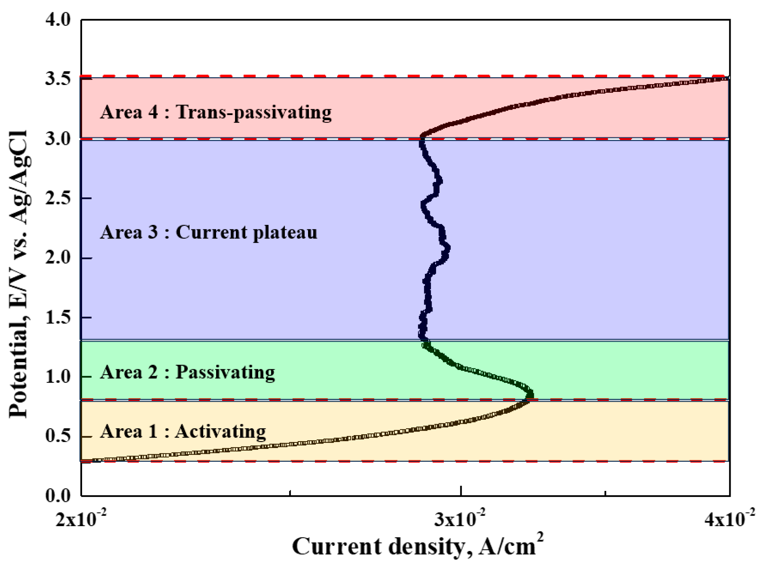
Figure 3.
Potentiodynamic polarization curves for UNS S31603 with DES composition ①: Active potentials, ②: Initial of plateau potentials, ③: Middle of plateau potentials, ④: End of plateau potentials, ⑤: Transpassive potentials for electropolishing.
Figure 3.
Potentiodynamic polarization curves for UNS S31603 with DES composition ①: Active potentials, ②: Initial of plateau potentials, ③: Middle of plateau potentials, ④: End of plateau potentials, ⑤: Transpassive potentials for electropolishing.
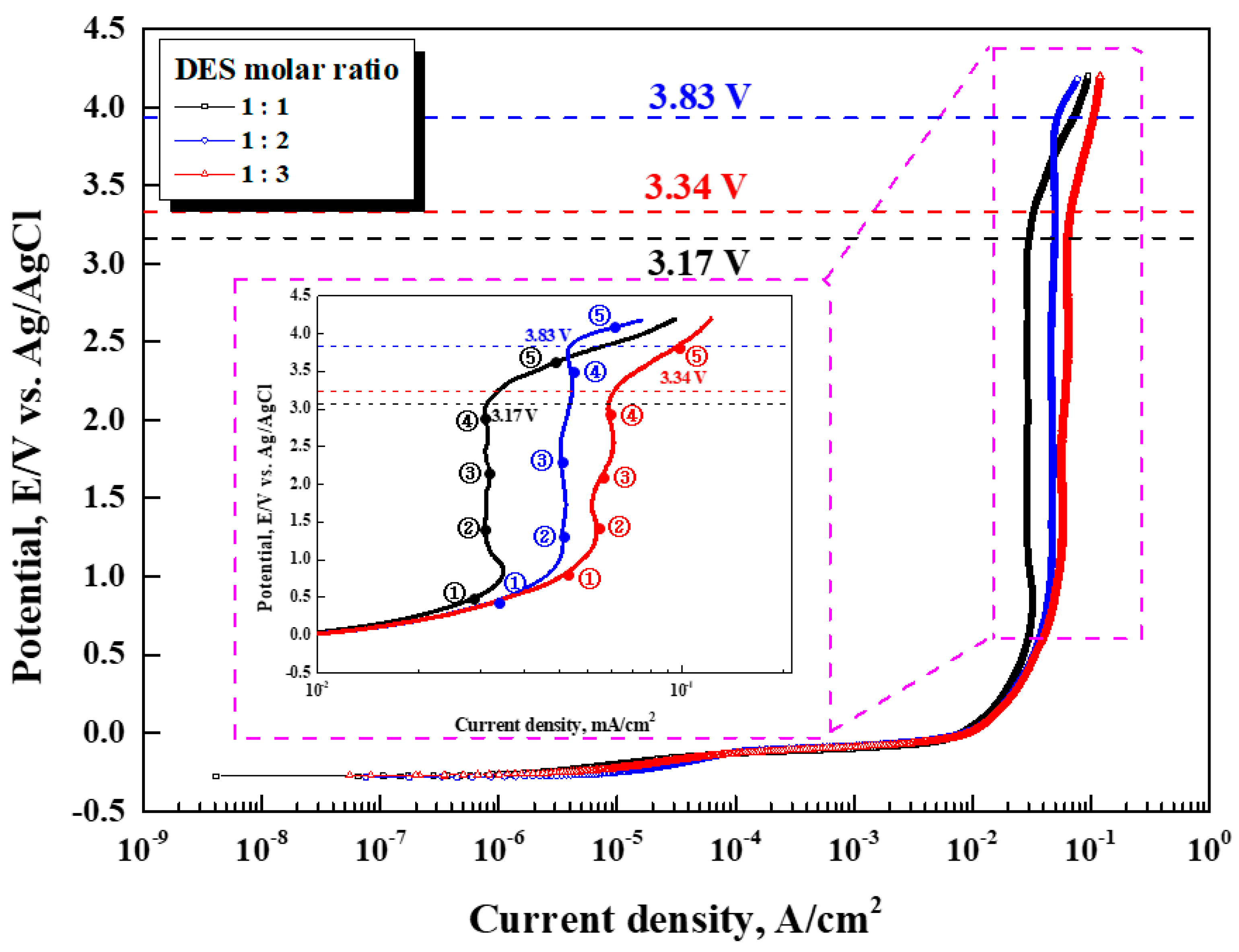
Figure 4.
Time - Current density curve and appearance after electroplishing with DES composition for UNS S31603.
Figure 4.
Time - Current density curve and appearance after electroplishing with DES composition for UNS S31603.
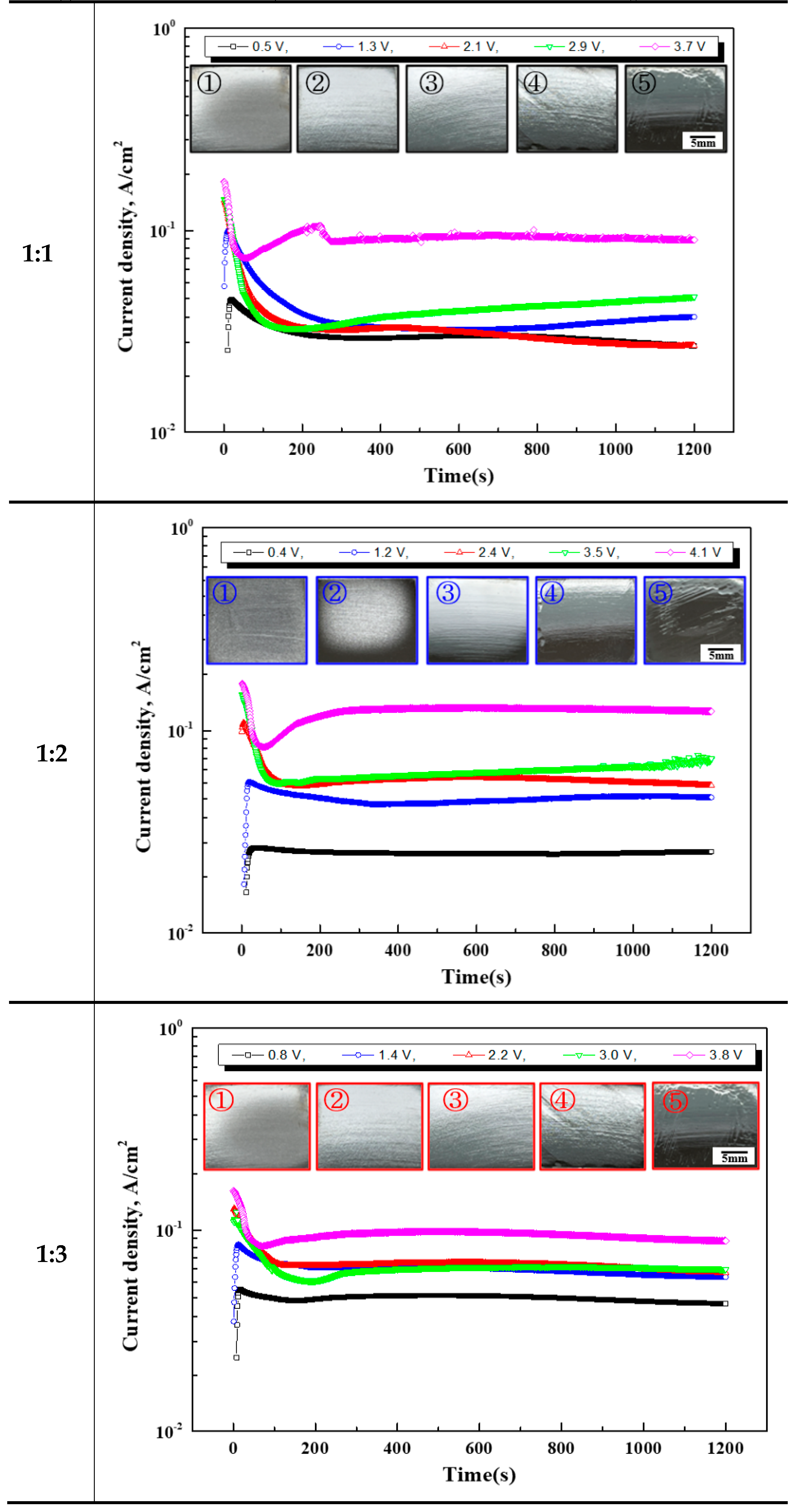
Figure 5.
2D, 3D image, and height between mountain and valley after electropolishing with DES composition for UNS S31603.
Figure 5.
2D, 3D image, and height between mountain and valley after electropolishing with DES composition for UNS S31603.
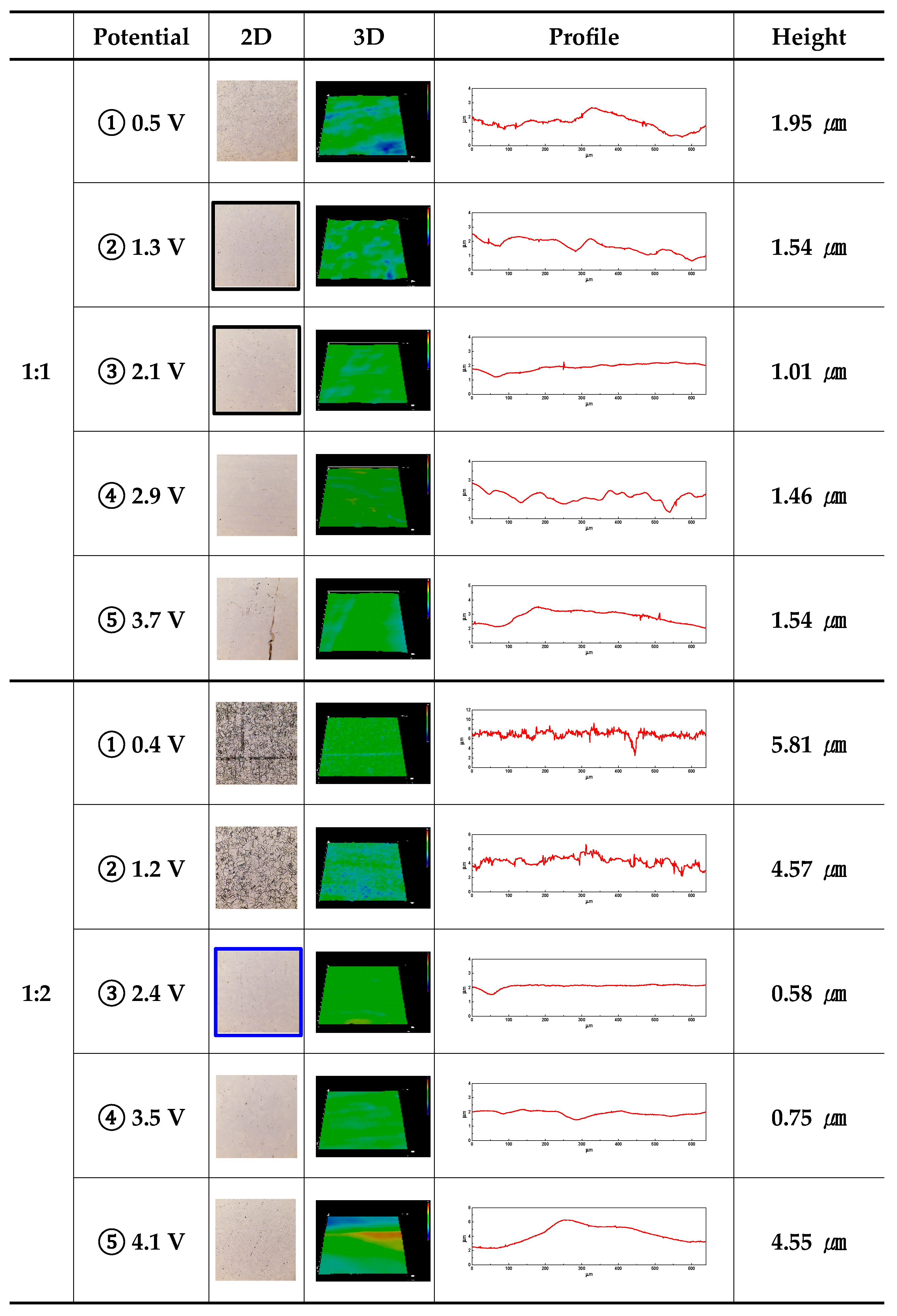
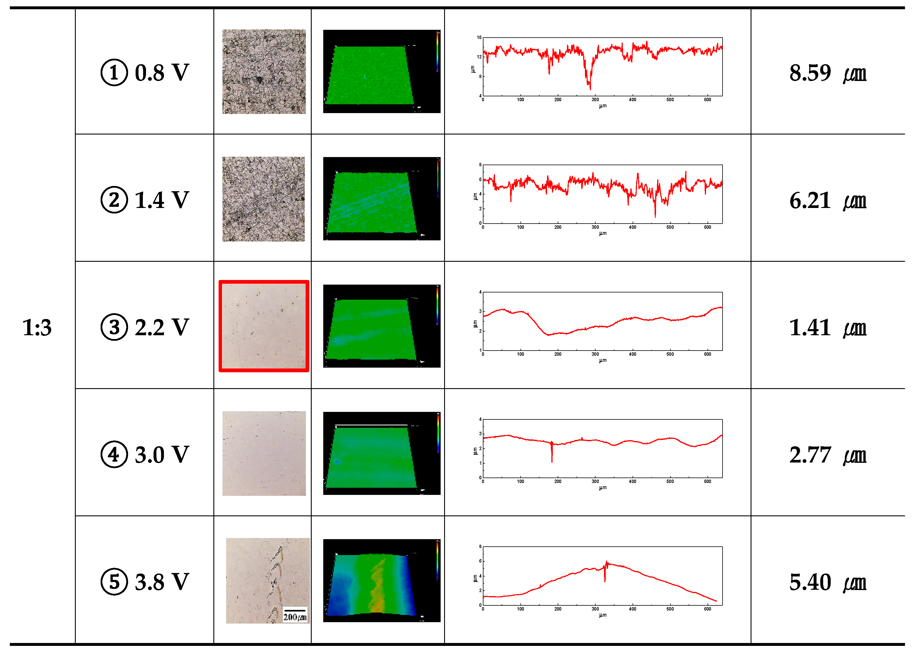
Figure 6.
Surface morphology and roughness after electropolishing with DES composition for UNS S31603.
Figure 6.
Surface morphology and roughness after electropolishing with DES composition for UNS S31603.
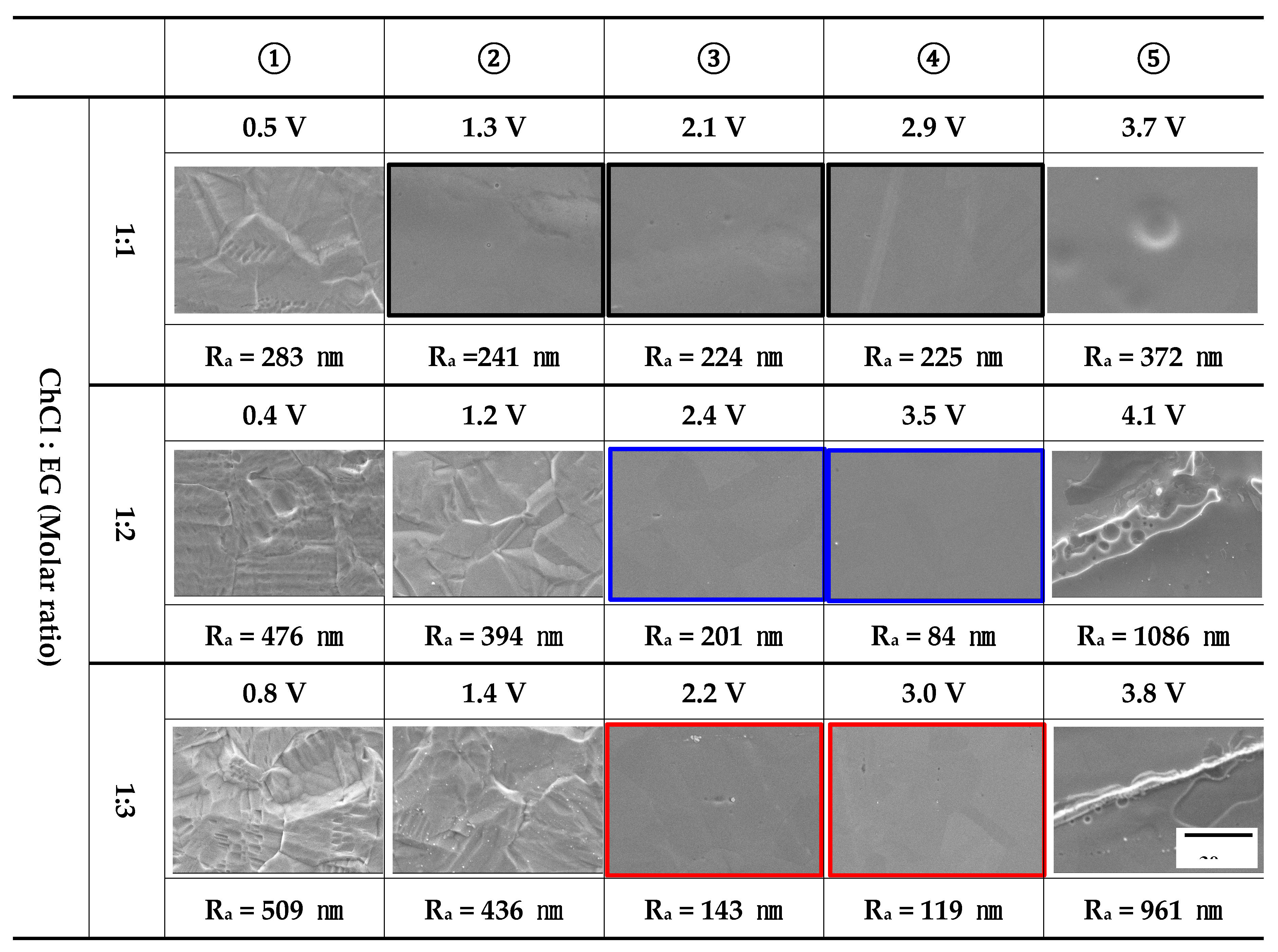
Figure 7.
Height (a) and roughness (b) comparison graph after electropolishing with DES composition for UNS S31603.
Figure 7.
Height (a) and roughness (b) comparison graph after electropolishing with DES composition for UNS S31603.
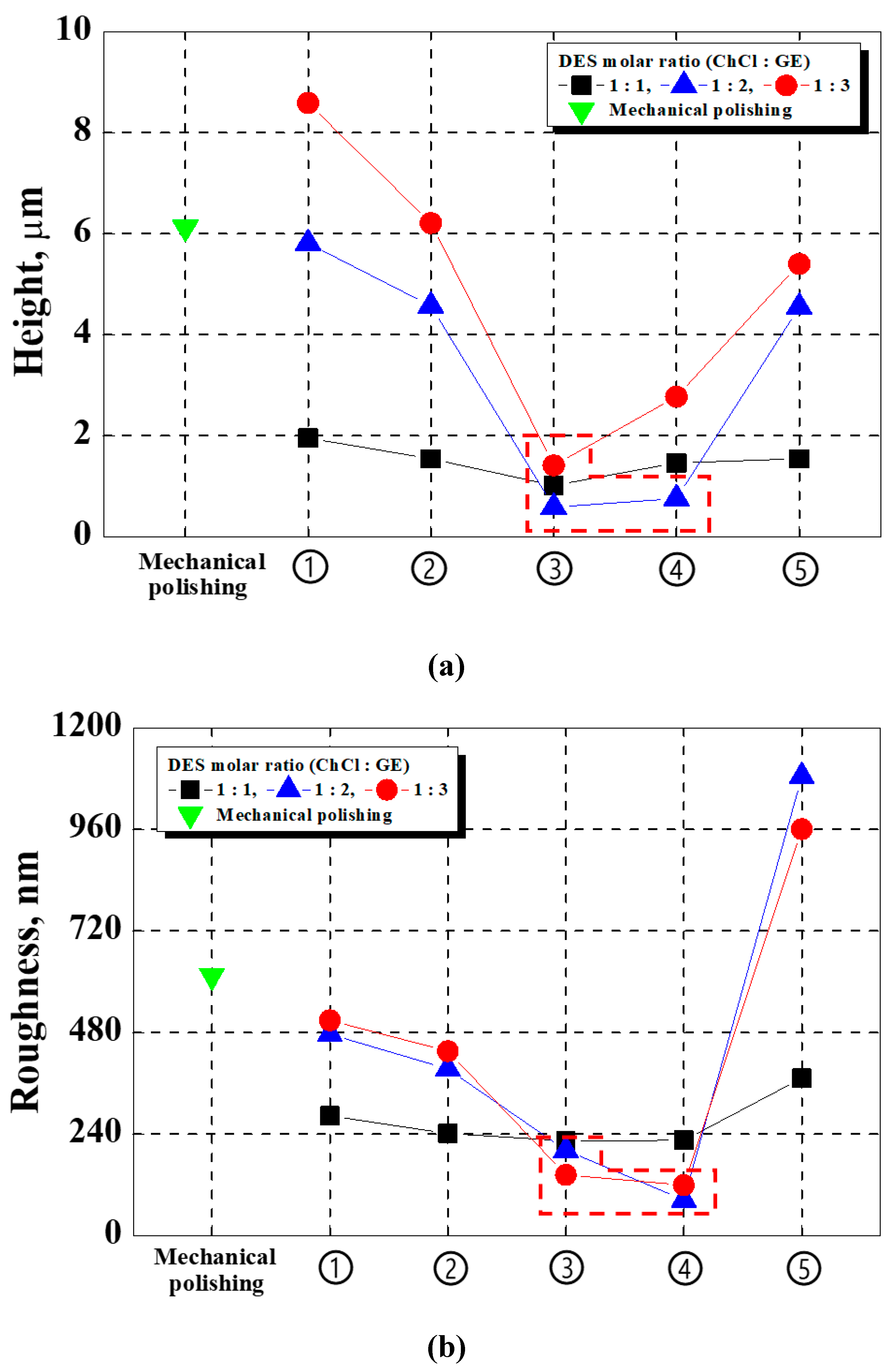
Figure 8.
XRD analysis with electropolishing.
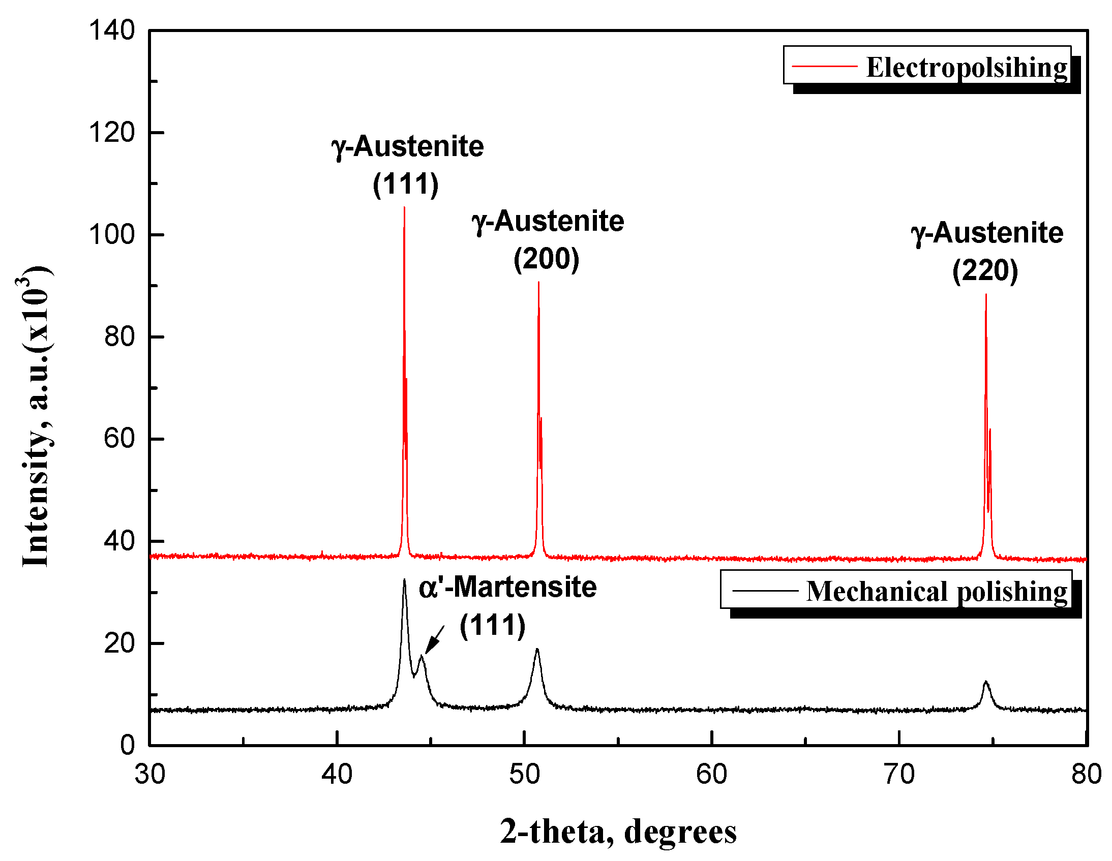
Figure 9.
Potentiodynamic polarization curves and electrochemical parameters.
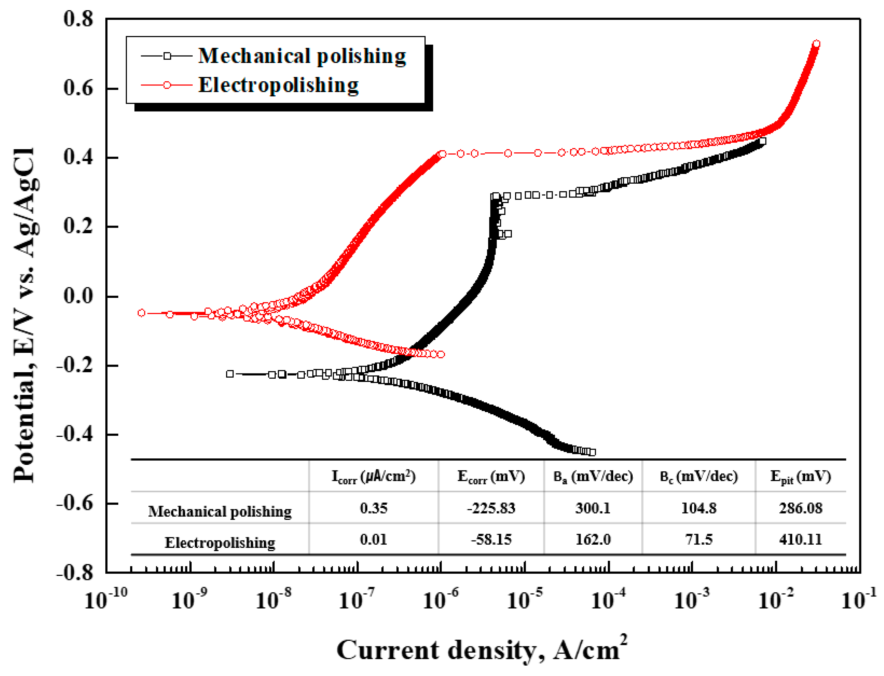
Figure 10.
Potentiostatic polarization curves and appearance at 0.35 V (vs. Ref.) in sea water with electropolishing.
Figure 10.
Potentiostatic polarization curves and appearance at 0.35 V (vs. Ref.) in sea water with electropolishing.
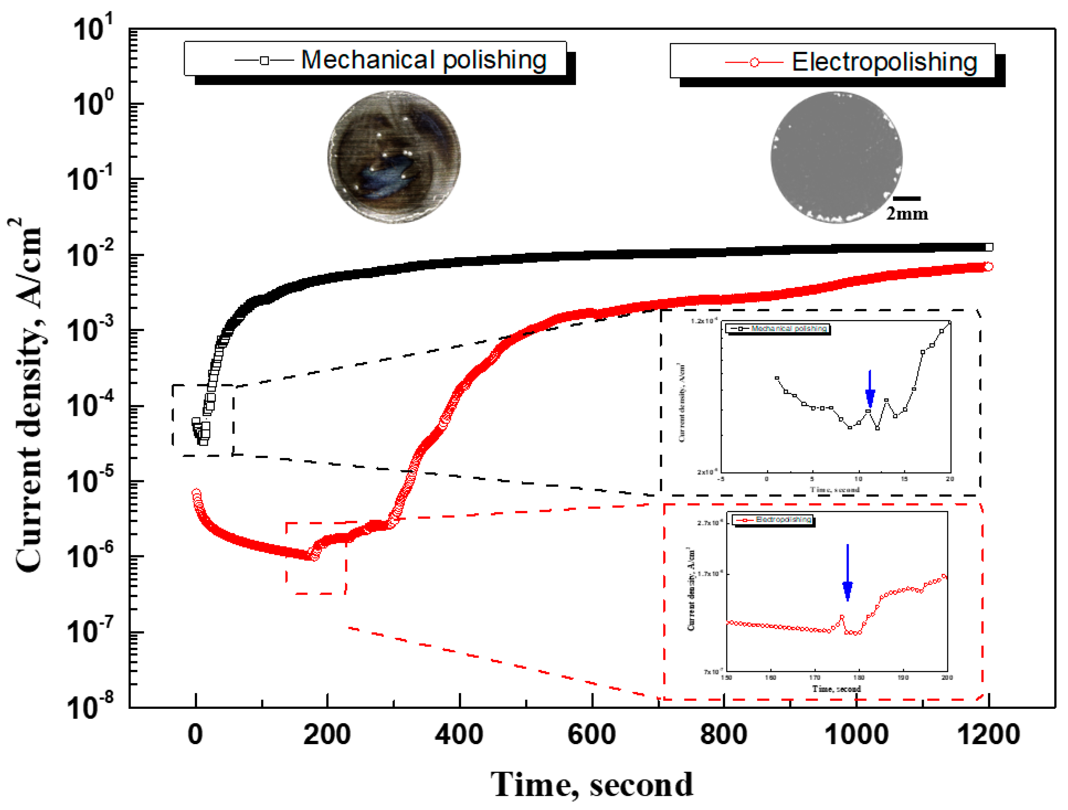
Figure 11.
3D profile after potentiostatic polarization experiment at 0.35 V (vs. Ref.) in sea water with electropolishing.
Figure 11.
3D profile after potentiostatic polarization experiment at 0.35 V (vs. Ref.) in sea water with electropolishing.
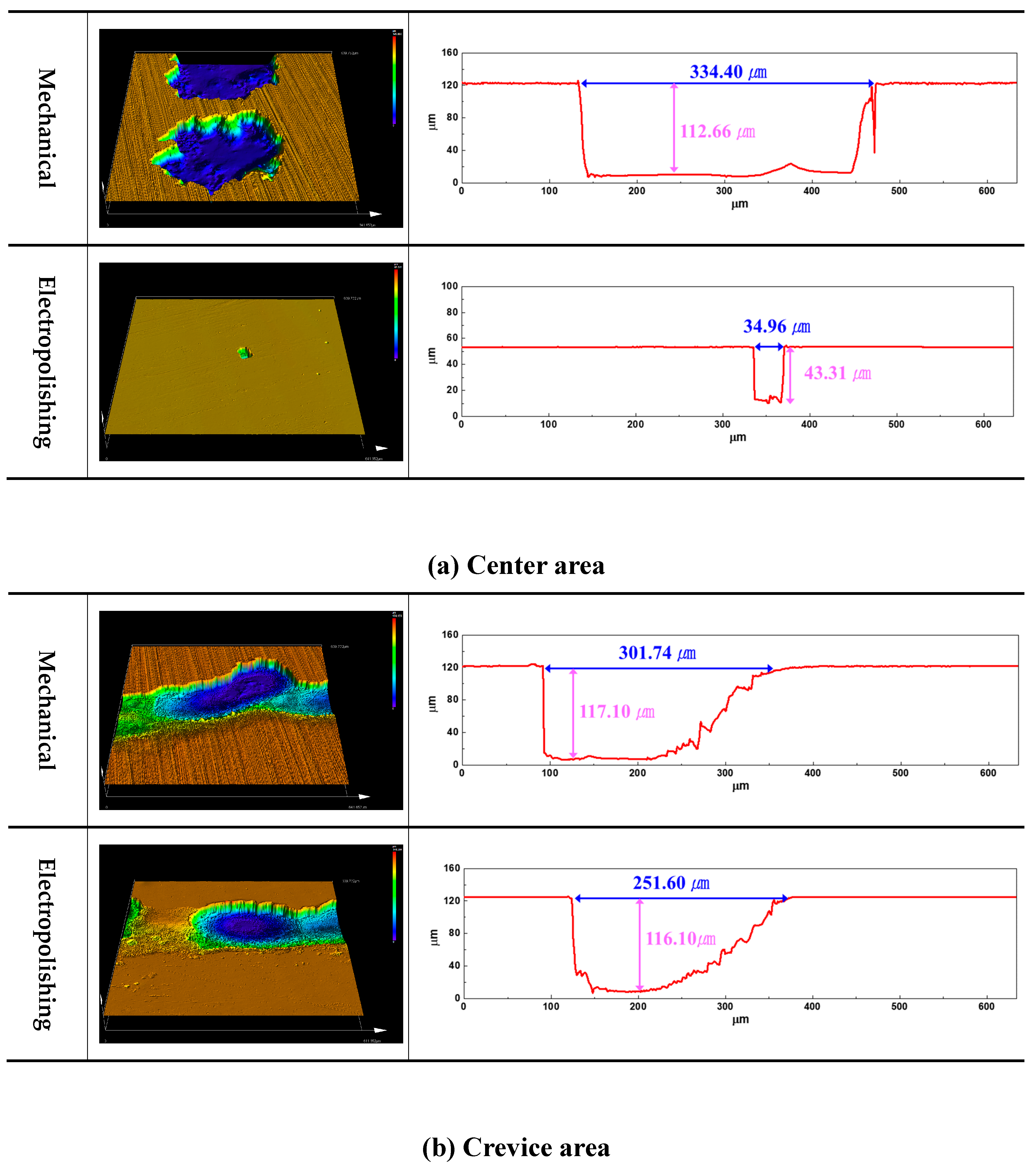
Figure 12.
SEM analysis after potentiostatic polarization experiment at 0.35 V (vs. Ref.) in sea water with electropolishing (Hatched area: sea water, Allow: Direction of crevice progression).
Figure 12.
SEM analysis after potentiostatic polarization experiment at 0.35 V (vs. Ref.) in sea water with electropolishing (Hatched area: sea water, Allow: Direction of crevice progression).
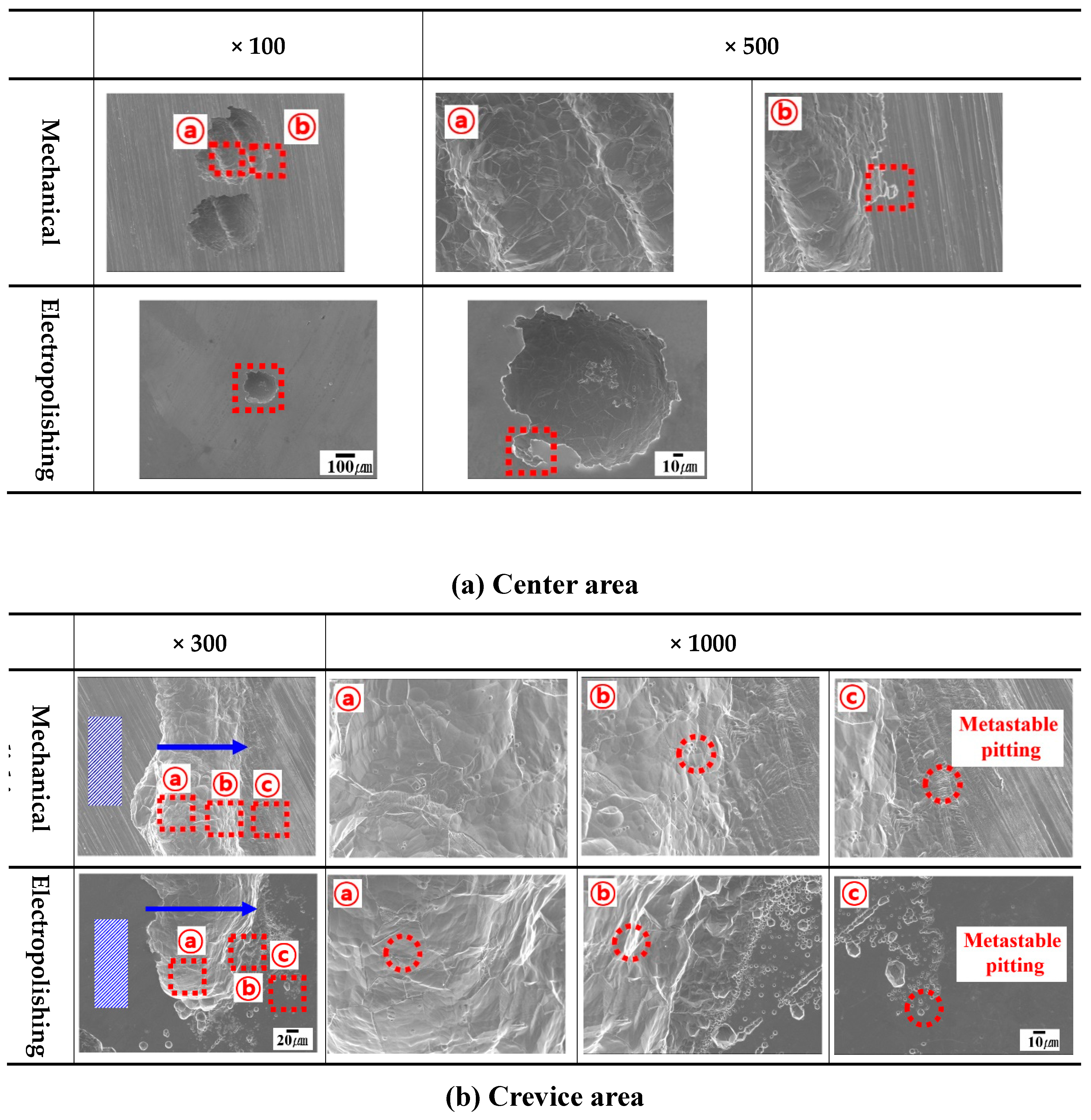
Figure 13.
EDS analysis after potentiostatic polarization experiment at 0.35 V (vs. Ref.) in sea water with electropolishing.
Figure 13.
EDS analysis after potentiostatic polarization experiment at 0.35 V (vs. Ref.) in sea water with electropolishing.
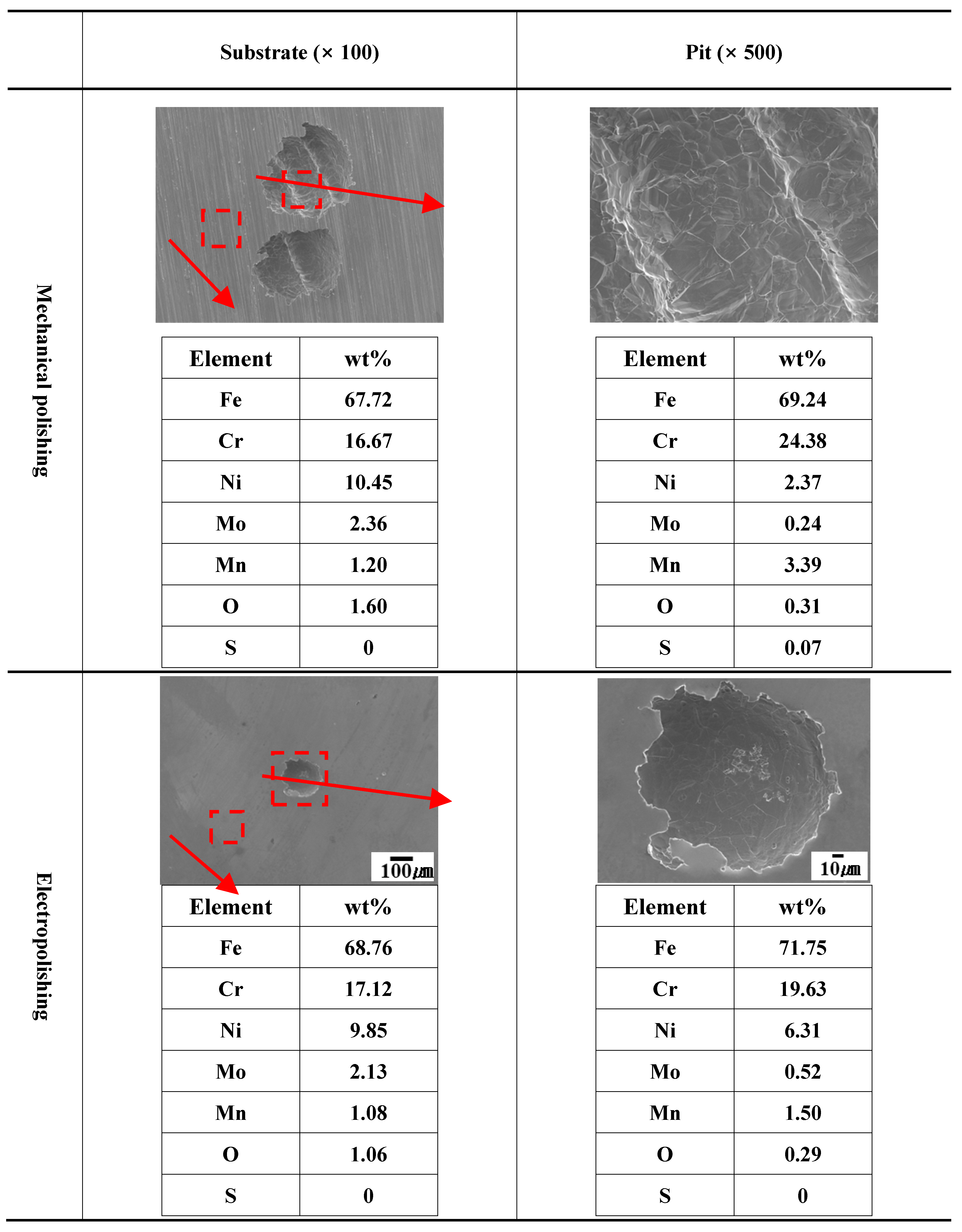
Figure 14.
Impedance spectra and interface model with electropolishing.
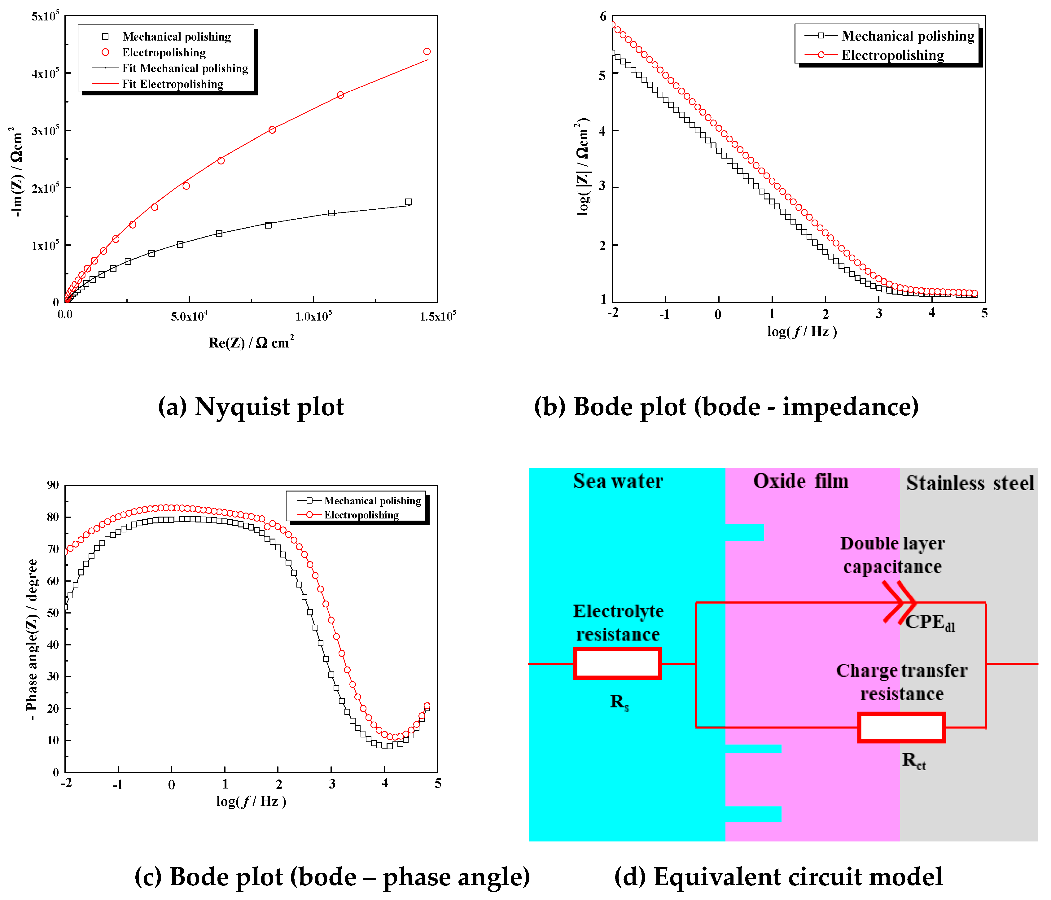
Figure 15.
Schematic diagram of the mechanism of electropolishing with ethylene glycol content (a) and for improving corrosion resistance through electropolishing (b).
Figure 15.
Schematic diagram of the mechanism of electropolishing with ethylene glycol content (a) and for improving corrosion resistance through electropolishing (b).
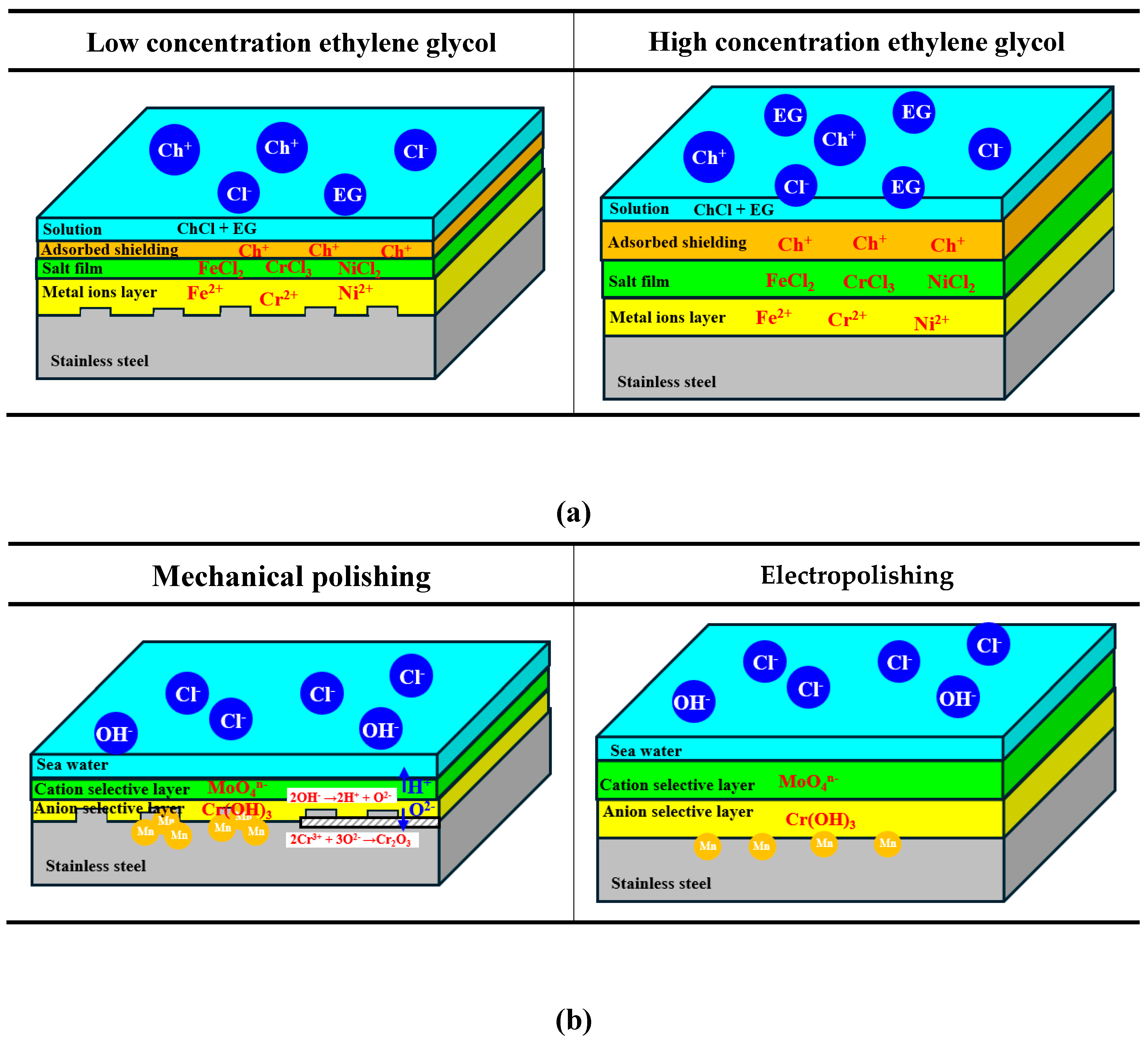

Table 1.
Electrolyte compositions (Deep Eutectic Solvents, DES) for electropolishing.
| Unit | Level (Molar Ratio) | ||
|---|---|---|---|
|
Choline Chloride (ChCl), 99 %/w : Ethylene glycol (EG), 99 %/w |
1 : 1 | 1 : 2 | 1 : 3 |
Table 2.
Chemical compositions and characteristics of sea water (wt%).
| Main Component (mg/L) | pH | Dissolved Oxygen (mg/L) |
Electric Conductivity (mS/cm) |
|||||
|---|---|---|---|---|---|---|---|---|
| SO42- | Cl- | Na+ | K+ | Mg2+ | Ca2+ | |||
| 1746 | 15721 | 8401 | 344 | 1121 | 357 | 7.9 | 16.1 | 45.3 |
Table 3.
Optimal conditions for electropolishing of UNS S31603.
| Electrolyte Composition (Molar Ratio) | Voltage | Temperature | Process Time |
|---|---|---|---|
| ChCl : EG = 1 : 2 | 2.4 V | 70 ℃ | 20 minutes |
Table 4.
Fitting parameters with electropolishing.
| Rs ( Ω cm2) |
Rct (kΩ cm2) |
CPEdl ( × 10-6 Ω-1 cm-2 sn) |
ndl | |
|---|---|---|---|---|
| Mechanical polishing | 13.8 | 438 | 43.51 | 0.89 |
| Electropolishing | 14.8 | 2196 | 16.21 | 0.92 |
Disclaimer/Publisher’s Note: The statements, opinions and data contained in all publications are solely those of the individual author(s) and contributor(s) and not of MDPI and/or the editor(s). MDPI and/or the editor(s) disclaim responsibility for any injury to people or property resulting from any ideas, methods, instructions or products referred to in the content. |
© 2025 by the authors. Licensee MDPI, Basel, Switzerland. This article is an open access article distributed under the terms and conditions of the Creative Commons Attribution (CC BY) license (http://creativecommons.org/licenses/by/4.0/).
Copyright: This open access article is published under a Creative Commons CC BY 4.0 license, which permit the free download, distribution, and reuse, provided that the author and preprint are cited in any reuse.


