
Submitted:
23 June 2025
Posted:
27 June 2025
You are already at the latest version
Abstract
The article presents a new AM (Additive Manufacturing) process development, necessary to repair parts made from aluminum 6061 material, with T6 treatment. The laser DED and EHLA capabilities are evaluated for repairing Al large components. To optimize the process parameters, single track depositions were analyzed for both conventional DED (feed rate of 2m/s) and high-speed DED/EHLA (feed rate 20m/s), for AlSi10Mg and Al6061 powders. The cross sections of single tracks revealed the bonding characteristics and provided a suitable parameter selection for the repair. Three damage types were identified on the Al component, to define the specification of the repair process and to highlight the capabilities of DED and EHLA in repairing intricate surface scratches and dents. Our research is based on variation of the powder mass flow and beam power, studying the influence of these parameters on the weld bead geometry and bonding quality. The evaluation criteria include bonding defects, crack formation, porosity and dilution zone depth. The bidirectional path planning strategy was applied with a fly-in and fly-out path for the hatching adjustment and acceleration distance. Samples were etched for a qualitative microstructure analysis and the HV hardness was tested. The novelty of the paper is the new process parameters for DED and EHLA deposition strategies, to repair large Al components (6061 T6), using AlSi10Mg and Al6061 powder. Our experimental research tested the defect-free deposition and the compatibility of AlSi10Mg on the Al6061 substrate. The readers could replicate the method presented in this article, to repair by DED/EHLA large Al parts and avoid the replacement of Al components by new ones.
Keywords:
direct energy deposition
; high-speed direct energy deposition
; circular economy
; repair
1. Introduction
The shift towards circular economy in manufacturing operations is a pressing challenge for the manufacturing industry. The shortage in raw material availability makes replacing a damaged component by a new one not only time- and cost-intensive, but also unsustainable, considering the emissions resulting from a new component manufacturing, transportation, and the old component scrapping.
Aluminum, with an increasing demand by 4% per year and an increasing price per ton by 60% in 2022, is a crucial material used in the mobility, mechanical, tooling and building industries. [1] Therefore, the development of efficient repair methods is gaining more interest, to avoid new component manufacturing. Additive manufacturing (AM), the layer-by-layer deposition of metal feedstock in powder or wire form, comes as a solution to repair damaged areas and to extend component lifetime.
Directed Energy Deposition (DED) is a subgroup of AM technologies, which uses a directed heat source – laser, electron beam, or arc – to melt a feedstock (wire or powder) material. [2] Flexibility is a key advantage of DED technologies, as the deposition doesn’t require support structures, thus the metal feedstock is directly deposited onto an existing base plate or, for repair applications, the damaged surface. The deposition nozzles can be integrated in existing CNC-machines or on robotic arms, making the repair of large volumes, possible.
The extreme high-speed version of conventional DED, the so-called “EHLA” (from German: Extremes Hochgeschwindigkeits-Laserauftragschweißen) is used to deposit dense, thin layers with an at least 10-times increased speed, and surface roughness reduced to a 10th of the ones produced by conventional DED. [3,4] The EHLA technology was initially deployed for coating rotationally symmetrical surfaces, such as brake discs, hydraulic cylinders, valves, even bearing journals. As such, the offshore industry implemented EHLA for coating hydraulic cylinders to improve the service life of components, protecting them against environmental conditions [3], the experiments conducted by Koss, S. highlight the efficient coating of Aluminum cylinder substrates with deposition speeds of 100m/min and 200m/min [1]. State-of-the art machine providers develop the EHLA deposition kinematics for cuboid or thin wall structures as well, a suitable development for repair applications.
2. Evaluation of the DED and EHLA Technologies
2.1. DED and EHLA Deposition Nozzles
The deposition nozzle design has a great influence on the deposition quality, defining the powder flow and shielding performance. In a conventional powder-based Laser-DED nozzle, a laser beam is activated to melt the feedstock material. In the nozzle, the carrier gas ensures the necessary drag force for the powder flow to fall into the convergence area, where the powder meets the laser. In most of the cases, a shielding gas (for ex. Argon) secures inert atmosphere in the convergence area, minimizing potential oxidation of the deposited layers. The laser deployment causes the creation of a molten pool on the target surface, into which, the molten powder is deposited, following a pre-programmed toolpath. [5]
The amount of powder falling onto the melt pool during the deposition process (also called catchment efficiency) is influenced by the powder feeding system design. Therefore, different types of nozzles were developed, enumerated by Guner, A. as follows: off-axis, discrete coaxial, continuous coaxial and inside-beam powder deposition nozzles. [5]
Off-axis nozzles feed the powder or wire in a unidirectional manner, especially for coating applications. For a defect-free deposition, the distance between the nozzle and laser beam and the inclination as to the laser beam direction need to be adjusted. This type of nozzle design is suitable for EBAM (electron beam AM), WAAM (wire arc AM), WLAM (wire laser AM) technologies, depositing large build volumes, with deposition track widths in the range of 0.5-25 mm and with high deposition rates (around 3-9 kg/h). [1,6]
Coaxial nozzles, as the name states, focus the laser beam and the powder flow coaxially. There are two main subcategories: continuous and discrete coaxial nozzles, with the main difference, that while continuous coaxial nozzles feed a single stream of powder to the laser beam, discrete coaxial nozzles feed multiple powder streams, usually 3, 4, and even 6, placed around the nozzle, each of them having its individual powder flow control.
The coaxial nozzles include concentric cones and in the gaps between them the powder, carrier gas is induced. The shielding gas protecting against oxidation is deployed from the center hole where the beam is also emitted. The gap size between the cones is adjustable, depending on the particle size, as well as the cone angles, with a suggested maximum angle of 20° being satisfactory. Adjusting the cone angle, the size of the laser beam is modified, which improves the nozzle efficiency, and ensures a uniform powder flow at the nozzle tip. [2,5]
To understand the difference between the conventional DED and EHLA process, it is essential to look at the differences in the positioning of the nozzle or powder gas jet in relation to the processing surface. Seemingly having the same type of feeding system, both DED and EHLA rely on a continuous coaxial nozzle design. What differs, however, is the nozzle tip positioning. As Figure 1. shows, in DED the focus position of the powder gas jet is positioned on the processing surface, while in EHLA set-up the powder focus is positioned above the processing surface.
This positioning is responsible for the fact that conventional DED creates the melt pool on the target surface, introducing significant heat in the substrate. The outward positioning, however, makes it possible to melt the metal powder before hitting the target surface, therefore creates a smaller melt pool, inducing less heat in the substrate. This process also reduces the melting time and allows for a fast feed rate, from a few m/min (as in conventional DED), to hundreds of m/min, from which the “extreme high-speed” characteristic of the EHLA technology. [2.5]
2.2. DED and EHLA Capabilities – Literature Review
Typically, DED is preferred to fabricate large volumes, due to the high deposition rates, increased layer thicknesses. The large volume deposition is successfully implemented especially in the aerospace industry, for Titanium, Nickel-based alloys, or steel applications, as it reduces machining time and raw material costs, increases the manufacturing capacity, by improving the component lead time. DED is deemed as a low-accuracy deposition type, compared to powder bed fusion. Even if there is no need to eliminate support structures or bonding agents, DED requires post-processing to obtain the desired surface quality.
In case of EHLA, as it is a relatively new development, literature reports more on the technology’s capabilities, the evolution from rotary symmetrical deposition [3] to cuboid volume [7] and thin wall deposition [8], and only a few connect it to industrial applications, such as coatings and repair. [1,9]
EHLA, as well as DED, makes it possible to mix powders, independently form melt pool kinetics and segregation processes. Li, J. et.al demonstrate the corrosion and wear resistance increase of a 5083 Al substrate, by depositing a Cu-Ni25 interlayer alloy and Ni-based surface alloy, with a process speed of 30m/min. This material combination extends component lifetime by increasing wear and corrosion resistance (tested in saltwater environment) and increases the microhardness of the surfaces around 5 times the microhardness of the Al substrate. [10]
The deposited layer forms a molten film on the substrate, with only ~20% of the laser power being absorbed by the substrate, and 80% by the powder, before hitting the target surface, [11] a reason why Al is a great candidate for EHLA depositions.
Comparing the EHLA microstructure with conventional DED deposition, it is noticeable, that the speed has an influence on the cell size, decreasing up to 3 times. [13] To give an example, Li, T. compares EHLA and DED deposition of AISI 4340 powder: to deposit 10 mm thickness, it takes 22 layers for DED and 95 layers for EHLA, while EHLA reduces the heat affected zone from 100-500 µm to 10-100 µm. [12]
DED repair research is focusing on reconstructing geometries prone to dents, wear, and scratches, mostly in stainless steel [13,14,15], Ni-based alloy [16,17] applications, and only a few experiments report on the outcomes of Al repair with DED.
The DED deposition of AlSi10Mg is more challenging, compared to stainless steel, Nickel base alloy or Titanium alloys, due to the material’s high reflectivity and oxidation characteristics and low laser absorption rate. [18,19] This is reflected in the investigations of Lv. F, as the laser power used for DED deposition is in the interval of 2000 – 3600 W for 0,5 mm layer thicknesses. Lv, F. presents the pore and crack free AlSi10Mg DED deposition, with a density of 99,2%, and draws the conclusion, that heat treating the deposited samples does increase the tensile strength by 17% and keeps the microhardness of the structure constant. [18]
Hermann, F. concludes with similar findings, depositing AlSi10Mg with laser powers between 2800-3600W, feed rate of 10g/min, achieving tensile strengths of 220MPa for the deposited cuboid volumes. [4]
Dong, E.; et.al investigate on the DED-repair of Al aeroengine casing components. Using 1800 W beam power, 0.7 mm thick layers were deposited, and the microstructure analysis reveals a crack-free deposition with pores distributed regularly. Microhardness tests strengthen the literature findings, with values in the interval of 78-85HV0.2. Tensile strength (UTS) of the deposited tracks result in 215 ± 12 MPa, compared to 225 MPa of the substrate, it is concluded that the AlSi10Mg deposition characteristics fulfil the repair requirements of aeroengine casing components. [19]
Koss, S. et.al demonstrate the successful coating of AlMgSi0.5 cylinders by depositing AlSi10Mg power with extreme high-speed: 100 and 200 m/min. For this application the special TruDisk8001 laser is deployed, to increase laser power up to 8000 W. With such high laser power, the mass flow is increased to 22-34 g/min to generate a 100 µm thin layer. With increased process speed, the productivity of the process goes up to 1300 cm2/min, a beneficial property for coating large volumes in an efficient way. [1]
Considering the literature findings, in this paper the bottlenecks of DED and EHLA for Al component repair are challenged, and its performance in accuracy, speed, and bonding characteristics, demonstrated.
3. Materials and Methods
3.1. Experimental Setup
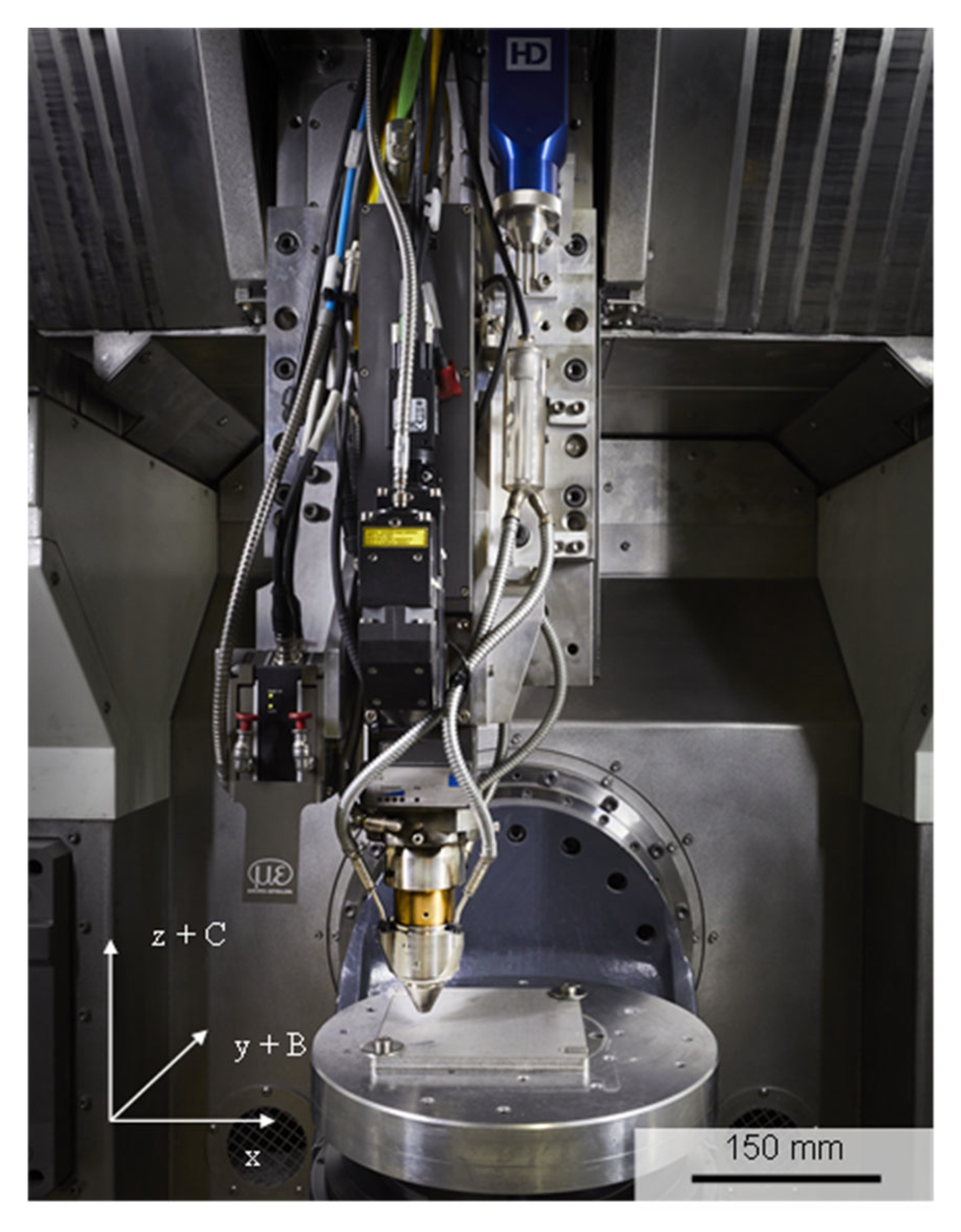
All experiments were conducted on a modified 5-axis CNC-machine AML500 developed by Makino Asia Pte. Ltd. The machine has workpiece dimensions of X:500 mm, Y:400 mm, Z:400 mm, and the maximum feed rate is 30 m/min. The powder nozzle is a continuous coaxial Highno. 4.0 from HD Sonderoptiken, with a stand of distance of 9 mm and a typical powder focus diameter of 0.7 mm at a powder mass flow of 3g/min. The powder feeder is a disk type feeder from Oerlikon Metco. The applied beam source is a LDF5000-30 with a OTZ5 processing optics from Laserline GmbH. The processing optics is equipped with an optical zoom system which can vary the focus and processing diameter between 1 mm ≤ df ≤ 3 mm.
Figure 2.
Experimental setup.
3.2. Materials
The damaged component is a 6061 Al spacer component, with T6 treatment. The spacer’s main functionality is to hold accurate distance, therefore the critical surfaces were investigated, where the distance accuracy was affected by surface scratches and dents. The T6 treatment consists of a solution heat treatment, to homogenize the composition by dissolving the soluble phases containing Mg, quenching and a natural or artificial aging at room temperature or increased temperatures on 150-210°C. [18]
For the process parameter evaluation, Al6061 material with a T6 heat treatment is used as a substrate. The powder material is also a matching Al6061 alloy from TLS ECKART and is specified with a powder particle distribution of 20 – 63 µm. Within the process parameter study, no sufficient EHLA parameters could be identified. Due to this, the study was extended with the powder material AlSi10Mg from FERHMANN for the EHLA experiments, as this alloy is commonly used in AM.

Table 1.
Chemical composition of Al6061, according to EN AW-6061.
| Material [%] | Al | Si | Mg | Fe | Ti | Zn | Mn | Cu | Cr | OE | OT |
|---|---|---|---|---|---|---|---|---|---|---|---|
| Bal. | 0.4-0.8 | 0.8-1.2 | ≤ 0.7 | ≤ 0.15 | ≤ 0.25 | ≤ 0.15 | 0.15-0.4 | 0.04-0.35 | ≤ 0.05 | ≤ 0.15 |
3.3. Single Track Process Parameter Study
In the first phase of the process study, a parameter study was conducted by depositing single tracks with a variation of selected process parameters (see Figure 3 (a)). Weld beads were deposited with 30 mm length and were qualitatively analyzed by metallographic cross-sections. The following criteria was used for the evaluation: bonding defects, crack formation, porosity and dilution zone depth.
The beam diameter is kept constant at dbeam = 1.2 mm, and the feed rate at vtool=20 m/min for EHLA and at vtool=2 m/min for conventional DED deposition. The shielding and carrier gases are also kept constant at Qshield = 12 l/min and QS = 8 l/min for DED and EHLA. By the variation of the powder mass flow and beam power, the influence of these parameters on the weld bead geometry and bonding quality can be analyzed. Following process parameter combinations are applied for the single-track experiments, listed in Table 2.
The process parameter set for DED and EHLA is selected respectively for the transfer to the coating process. Furthermore, the single tracks resulting from the selected process parameter sets are etched for a qualitative microstructure analysis. As an initial evaluation of the mechanical property resulting from a local single-track repair, the etched cross-section is used for HV hardness measurements.
3.4. Single Layer Process Parameter Study
In the second phase of the parameter development, the selected DED and EHLA parameters are used to deposit a single layer coating. For the single layer deposit, the process parameters listed in Table 3. were used.
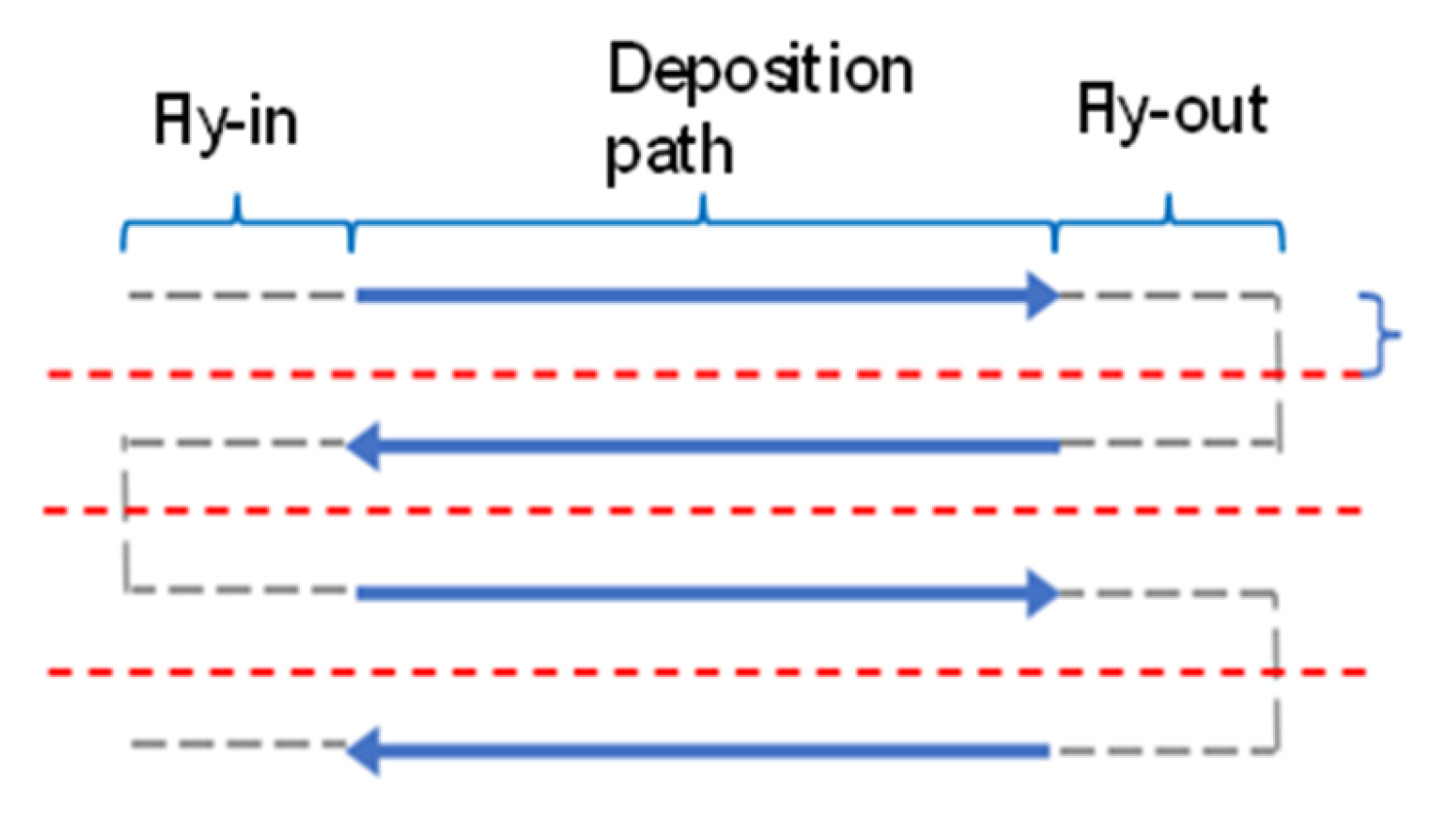
Within this study, the bidirectional path planning strategy is applied with a fly-in and fly-out path for the hatching adjustment and acceleration distance (see Figure 5).
Figure 4.
Applied path planning strategy for the single layer deposition.
For the evaluation, each coating specimen is metallographically analyzed by an etched cross-section. Similar to the single tracks, the initial evaluation of the mechanical properties is conducted by HV hardness testing.
4. Results and Discussion
4.1. Single Track Process Parameter Study
Within the initial DED parameter study the beam power was varied between 1000 W ≤ P ≤ 2500 W in 100 W increments. The results indicate that a minimum beam power of P = 1100 W is required for a sufficient metallurgical bonding. Below this beam power threshold, the deposited single tracks are either partly or not bonded to the substrate material. The variation of the beam power indicates that the applied beam power affects the pore formation within the deposited track (Figure 5).
After a sufficient metallurgical bonding can be assured with an applied beam power threshold, a lower beam power tends to more and bigger pore formation. Increasing the beam power reduces the size and number of pores, however, within the study a pore formation could not be fully avoided. After the minimum pore size and number at P= 2300 W the pores tend to increase with higher beam power. A possible mechanism for this tendency is that already formed pores can dissolve and diffuse out of the melt pool at higher melt pool temperatures, the resulting lower melt pool viscosity and slower solidification time. Too high beam power can result in turbulent melt pools which might enclose more pores. Based on the initial study, the parameter set with the beam power of P = 2300 W is selected for the further repair evaluation. The qualitative evaluation of the microstructure indicates the Al-matrix with the Mg2Si precipitates of the T6 Al6061 substrate. The deposited weld track as well as the dilution zone have a homogenous microstructure with no evident grain formation and precipitation (see Figure 6 (a)). For the material property eva-luation, hardness measurement is conducted in the weld bead, dilution zone and substrate material (see Figure 6 (b)).
According to the hardness measurement the T6 heat treated Al6061 substrate has an initial hardness value of 86 ± 3.7 HV. Due to a missing heat treatment, the as deposited single-track has a lower hardness value (see Table 4). Due to this and depending on the end specification, a component repaired by DED can require a heat treatment as an additional post processing step.
Within this study, all Al6061 single tracks deposited by EHLA have critical defects, like insufficient bonding or solidification cracks. The solidification cracks are formed vertically through the whole weld bead and dilution zone (see Figure 7), and indicate that the rapid solidification effect of the EHLA process is not beneficial for the Al6061 alloy.
Because of this, the single-track study was continued with the alloy AlSi10Mg, which is typical Al-alloy for additive manufacturing, compatible with the Al6061 substrate, as defects free single-tracks could be deposited at both ṁ = 5 g/min and ṁ = 10 g/min (see Figure 8).
Due to the higher powder mass flow, single-tracks deposited with ṁ = 10 g/min generally have a bigger weld bead geometry than the single-tracks deposited with ṁ = 5 g/min. Solidification cracks are formed when beam power of P > 2300 W and lower powder feed rate of ṁ = 5 g/min are applied. Tendencies of pore formation can be identified when a higher powder mass flow of ṁ = 10 g/min and lower beam power of P = 2000 W are applied. Similar to DED, the enclosure of pores can be mitigated when the melt pool temperature is increased by using higher beam power. For the repair application, the process parameter set with P = 2500 and ṁ = 10 g/min is selected for a higher rate of productivity. According to the etched cross-section, the depth of the dilution zone is ~ 100 µm higher than the deposited weld bead, which can result in the mixture of the Al-alloys and a change of the material properties. For the evaluation of the material properties, hardness tests were conducted similar to the DED single track (see Figure 9).
According to the hardness test results (see Table 5), the hardness of the deposited single-track exceeds the hardness of the substrate material at an as built state by ~100 HV. This indicates that no heat treatment of a repaired component is required as an additional post processing step. The hardness in the dilution zone is comparable to the hardness of the substrate. At the interface zone, the hardness reaches a minimum at 80 HV, which indicates the local dilution of both alloys.
4.2. Coating Process
In the second phase, process parameters from the single-track phase were selected for the deposition of single layer coatings to investigate the repair of extended defects like dents and scratches. The process parameters listed in Table 6. were selected for the single layer analysis.
For the DED single layer coating, the applied hatch distances were variated by 40 %, 50 % and 60 % track overlap (see Figure 10). Although the DED single-track has no critical defect formation, the coating specimens have a considerable higher porosity as well as cracks. The pores are particularly formed at the interfaces of each overlapping weld bead. Due to this, further investigations regarding adapted path planning strategies and process parameters are required for a defect free deposition with DED.
In contrast to the DED process, a defect free layer deposition is feasible by using the EHLA process and AlSi10Mg alloy (see Figure 11). The parameter sets with P = 2600 W and P = 2900 W results in a nearly defect free coating. Statistically distributed pores can be identified at P = 2500 W. For the evaluation of the material properties, hardness tests were conducted with the coating resulting from the parameter set with P = 2600 W (see Figure 12).
Similar to the single-track, the hardness of the coating exceeds the hardness of the substrate material (see Table 7). In addition to that, the hardness of the dilution zone stays in the same range as the substrate material. This indicates that a repair process can still be conducted for larger defects by applying the EHLA process.
5. Case Study
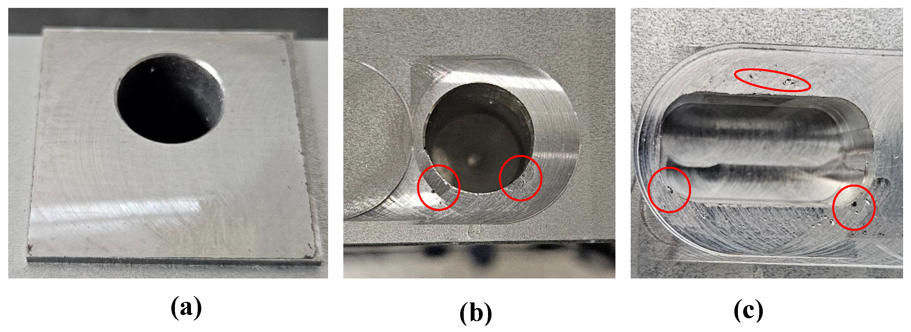
The purpose of this section is to test the new repair process for a 6061 Aluminum component. The spacer component holds critical distance in the machine. During installation it comes in contact with stainless steel parts, and critical surfaces get scratched, small dents appear around milled pockets, therefore the component gets rejected and a replacement by new is required. As Aluminum milling is both time and cost-efficient, the manufacturer prefers the replacement over repair. However, the demonstration of the repair can also open the door for larger, high-value component identification in large assemblies, where a localized DED/EHLA-repair of Aluminum does add value. After visual inspection, the damages showcased on Figure 13. were identified for repair.
Figure 13.
Preprocessed areas: (a) surface milling, (b) dent milling, (c) dent milling.
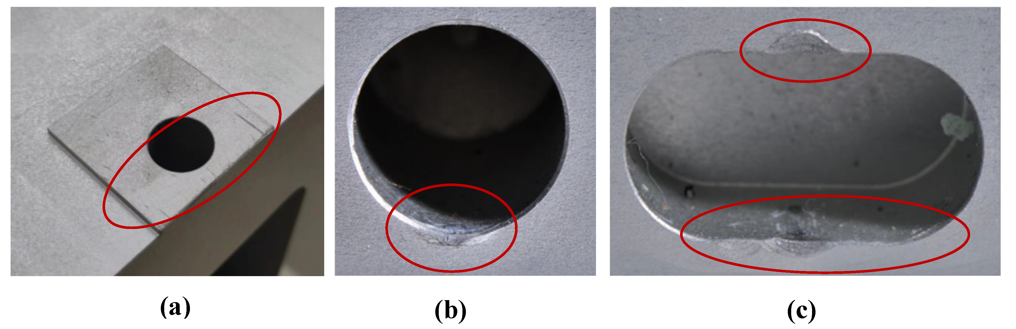
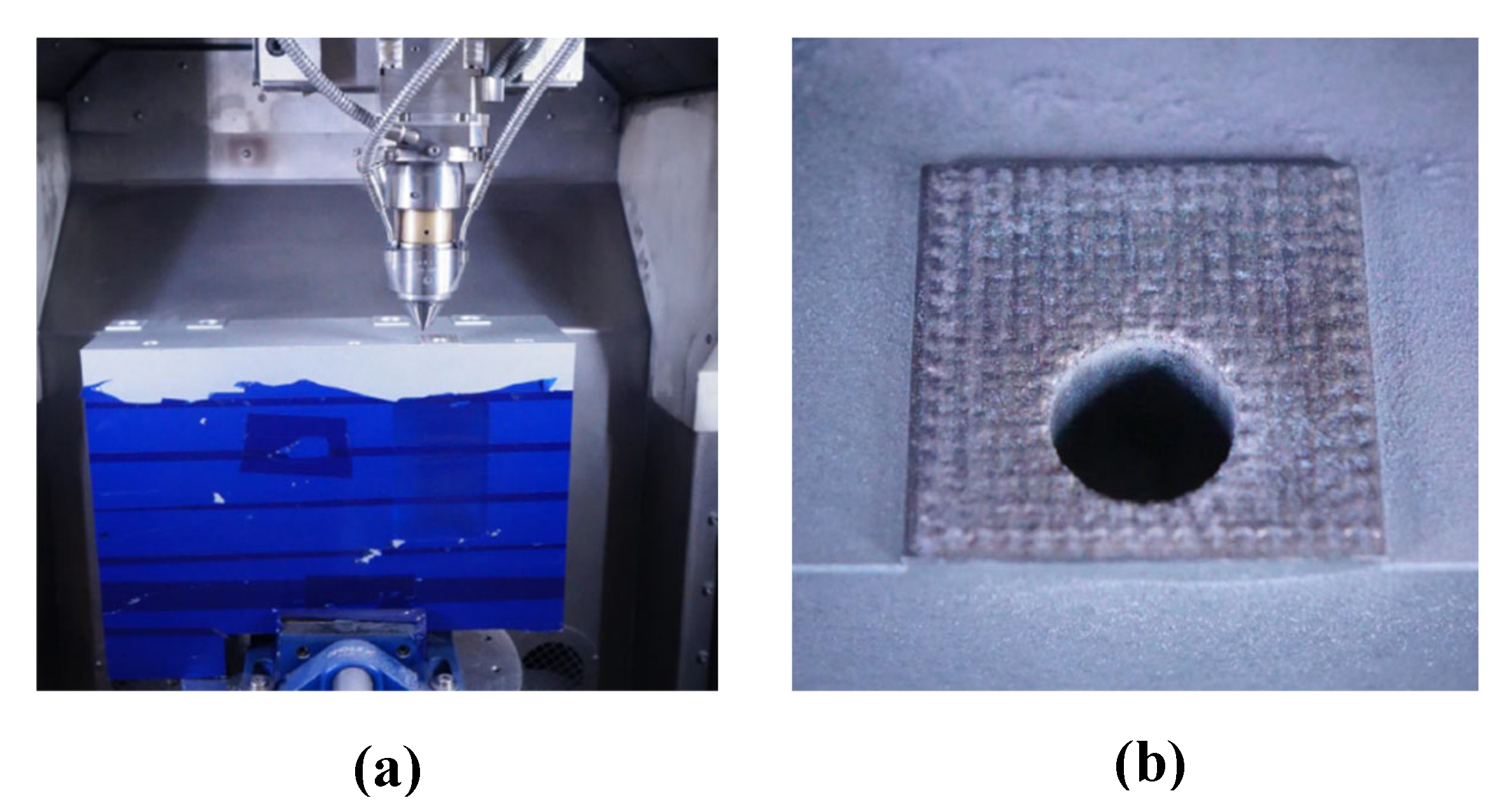
As the damage sizes are in the range of 0.1-1 mm depth, a pre-processing milling operation was necessary to prepare a more accessible deposition area around the edge dents and ensure necessary bonding with the substrate. The 30 x 30 mm surface was entirely preprocessed. For the surface repair the AlSi10Mg powder was EHLA-deposited using two lay-ers. For the deposition Argon gas was used as carrier and shielding gas, with a carrier gas flow of QC=8 l/min and shielding gas flow of QS=12 l/min. The component was fixed horizontally, and the single track were deposited with a 50% overlay.
Figure 13.
(a) Machine setup for EHLA repair; (b) EHLA deposition before post-processing.
The DED deposition approach was tested to repair the pocket dents. The toolpaths were deployed manually, iteratively programming several single-track depositions. For the DED repair of the edge dent the Al6061 powder was used.
The component was fixed in a 45° tilted position for better deposition head access and to ensure a 90° deposition angle to the processing surface (see Figure 14). As an initial demonstration the surface gradients at the edge of the chamfers were neglected within this study. To obtain the original geometry, a post-processing milling operation is performed.
Figure 14.
(a) Tilted machine setup for EHLA repair, (b) Setup for DED repair, (c) Filling of milled chamfer with DED single tracks.
Figure 14.
(a) Tilted machine setup for EHLA repair, (b) Setup for DED repair, (c) Filling of milled chamfer with DED single tracks.

Figure 15.
(a) post-processed surface area, (b) + (c) post-processed pockets with pores at the edge areas of the chamfer.
Figure 15.
(a) post-processed surface area, (b) + (c) post-processed pockets with pores at the edge areas of the chamfer.
After the post-processing the majority of the filled surface area is defect free, however, pores formation can be identified at the edge areas of the filled chamfer. The pore formation is likely caused by a non-perpendicular deposition condition caused by the simple and manual single track path planning. At later stages and maturation of the process chain an automated path planning, which considers the gradient at the chamfer areas, potentially avoids the defect formation at the edge areas. Still, a potential repair process for Al components is conceptually demonstrated as the majority of the filled surface area is defect free.
6. Conclusions
The new process parameters and improved DED/EHLA capabilities were tested and validated for competitive repairing the Al 6061 components with three different types of damages.
- Both conventional laser DED and EHLA processes result in crack and porosity-free deposition on Al6061 substrate, showcasing the potential of using this approach for large-scale repair of intricate damages.
- The Vickers measurement demonstrates increased microhardness (100 HV) of EHLA-deposited tracks for AlSi10Mg powder, compared to the Al6061 substrate (81 HV). To measure and adequately compare the microhardness of EHLA-deposited Al6061 tracks, further development of the process parameters is needed, considering the effects of surface treatment on microhardness.
- The EHLA deposition of Al6061 results in cracked single-beads, however the defect-free deposition and compatibility of AlSi10Mg on the Al6061 substrate is demonstrated. Increased beam powers between P = 2600 – 2900 W result in crack- and pore-free single beads and single layers.
- For the Al6061 powder, based on single track analysis, defect free tracks were obtained in the DED deposition, with vtool=2 m/min, powder mass flow of 5g/min and laser power between 1900 - 2500 W. For the EHLA deposition, with vtool=20 m/min, increased powder mass flow of 10g/min and increased laser power between 2600 - 2900 W results in defect free deposition.
- The initial demonstration of the damage repaired indicates a feasible repair process of Al parts by DED and EHLA. However, further in-depth research regarding the tool path strategy for filling out milled chamfers are required. The creation of pores is observed at the locations where a perpendicular deposition to the surface could not be guaranteed in scope of a manual programming. In perspective, a scanning-based tool path generation can be employed to automatically generate tool paths for individual defects.
Author Contributions
Conceptualization, A.M. and M-U.K.; methodology, M-U.K and R.K..; software, M-U.K.; validation, A.M. and M-U.K.; formal analysis, A.M. and M-U.K.; investigation, A.M. and M-U.K.; resources, A.M. and M-U.K.; data curation, M-U.K. and R.K.; writing—original draft preparation, A.M.; writing—review and editing, M-U.K and N.B.; project administration, A.M.; funding acquisition A.M. All authors have read and agreed to the published version of the manuscript. All authors have read and agreed to the published version of the manuscript.
Funding
This research was funded by Capgemini Engineering the Netherlands, under internal PO. 4130024464, as part of a bilateral cooperation between Capgemini Engineering the Netherlands and Fraunhofer ILT.
Data Availability Statement
We encourage all authors of articles published in MDPI journals to share their research data. In this section, please provide details regarding where data supporting reported results can be found, including links to publicly archived datasets analyzed or generated during the study. Where no new data were created, or where data is unavailable due to privacy or ethical restrictions, a statement is still required. Suggested Data Availability Statements are available in section “MDPI Research Data Policies” at https://www.mdpi.com/ethics.
Acknowledgments
The authors would like to thank Capgemini Engineering the Netherlands’ management team for making this work possible and the Fraunhofer ILT’s facility for strongly supporting this work.
Conflicts of Interest
The authors declare no conflicts of interest. The funders had no role in the design of the study; in the collection, analyses, or interpretation of data; in the writing of the manuscript; or in the decision to publish the results.
Abbreviations
The following abbreviations are used in this manuscript:
| DED | Directed Energy Deposition |
| EHLA | Extreme high-speed directed energy deposition |
| Al | Aluminum |
| EBAM | Electron beam additive manufacturing |
| WAAM | Wire arc additive manufacturing |
| WLAM | Wire laser additive manufacturing |
References
- Koss, S.; Vogt, S.; Goebel, M.; Schleifenbaum, J.H. ; Coating of Aluminum with High Deposition Rates through Extreme High-Speed Laser Application, J. Thermal Spray Technology, 2023, 32, 1689–1697. [Google Scholar] [CrossRef]
- Priscopo, G.; Atzeni, E.; Saboori, A.; Salmi, A. ; An Overview of the Process Mechanisms in the Laser Powder Directed Energy Deposition, Appl. Sci. 2023, 13(1), 117. [Google Scholar]
- Schopphoven, T.; Gasser, A.; Backes, G. ; EHLA: Extreme High-Speed Laser Material Deposition, Economical and effective protection agains corrosion and wear. Laser Technik Journal, 2017, 14. [Google Scholar] [CrossRef]
- Hermann, F. ; et al, al, Laser Metal Deposition of AlSi10Mg with high build rates. Procedia CIRP, 2022, 111, 210–213. [Google Scholar] [CrossRef]
- Guner, A. ; et al, Nozzle design in powder-based direct laser deposition: a review. International Journal of Precision Engineering and Manufacturing, 2022, 23, 1077–1094. [Google Scholar] [CrossRef]
- DIRECT ENERGY DEPOSITION (DED) – A comparison of multiple metal 3D printing methods. Available online: on www.ramlab.com/resources/ded-101/ (accessed on 10/01/2024).
- Ko, M-U.; Zhang, Z.; Schopphoven, T., Process development and process adaptation guidelines for the deposition of thin-walled structures with IN718 using extreme high-speed directed energy deposition (EHLA3D). Journal of Laser Applications 2023, 35, 042059. [CrossRef]
- Schaible, J.; Hausch, D.; Schopphoven, T. , Haefner, C.; Deposition strategies for generating cuboid volumes using extreme high-speed directed energy deposition. Journal of Laser Application, 2022, 34, 042034. [Google Scholar] [CrossRef]
- Liang, Y. ; A review on coatings deposited by high-speed laser cladding: processes, materials and properties. Optics and Laser Technology, 2023, 164, 109472. [Google Scholar] [CrossRef]
- Li, J. ; et.al, Ni-based coating on 5083 Aluminum alloy with Cu-Ni interlayer fabricated by ultra-high-speed laser directed energy deposition. Surface, and Coatings Technology, 2023, 474, 130068. [Google Scholar] [CrossRef]
- Buessenschuett, K. ; et al, High-Speed direct energy deposition as a high-throughput design tool for laser-based additive manufacturing. Additive Manufacturing Letters, 2024, 8, 100188. [Google Scholar] [CrossRef]
- Kanishka, K.; Acherjee, B. ; A systematic review of additive manufacturing-based remanufacturing techniques for component repair and restoration. Journal of Manufacturing Processes 2023, 89, 220–283. [Google Scholar] [CrossRef]
- Oh, W.J. ; et al, Repairing additive-manufactured 316L stainless steel using direct energy deposition. Optics and Laser Technology 2019, 117, 9–17. [Google Scholar] [CrossRef]
- Perini, M.; Bosetti, R.; Balc, N. ; Additive manufacturing for repairing: from damage identification and modeling to DLD. Rapid Prototyping Journal, 2020, 26, 929–940. [Google Scholar] [CrossRef]
- Xu, H. ; et.al, In-situ hot rolling directed energy deposition – arc repair of shafts. Additive Manufacturing 2023, 61, 103362. [Google Scholar] [CrossRef]
- Zhang, Y.; Lan, L.; Shi, Q. Microstructural evaluation and precipitated phase characteristics in the fusion zone for the as-repaired Inconel 718 alloy by directed energy deposition additive manufacturing. Materials Characterization 2023, 204, 113222. [Google Scholar] [CrossRef]
- Ferreira, N.M. Direct Energy Deposition Parametric Simulation Investigation in Gear Repair Application. MDPI Materials 2023, 16, 3549. [Google Scholar] [CrossRef] [PubMed]
- Lv, F. ; et.al, Mechanical properties of AlSi10Mg alloy fabricated by laser melting deposition and improvements via heat treatment. Optik – International Journal for Light and Electron Optics 2019, 179, 8–18. [Google Scholar] [CrossRef]
- Dong, E. ; et.al, Laser metal deposition of AlSi10Mg for aeroengine casing repair: microhardness, wear and corrosion behavior. Materials Today Communications 2024, 38, 108412. [Google Scholar] [CrossRef]
Figure 1.
DED and EHLA nozzle types: (a) DED, (b) EHLA, (reproduced based on [2.5]).
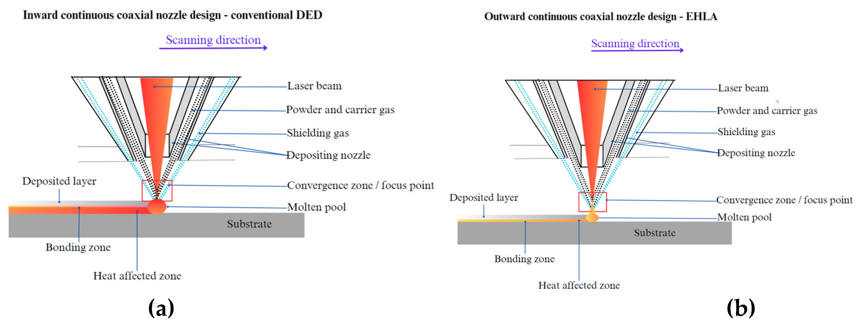
Figure 3.
(a) Example of DED single tracks, (b) Metallographic cross-section.
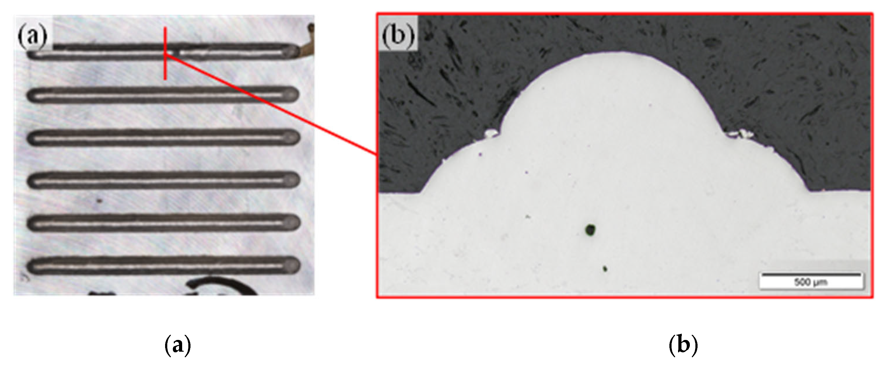
Figure 5.
Single track results: d=1.2 mm; ṁ = 5 g/min; QC = 8 l/min; QS = 12 l/min.
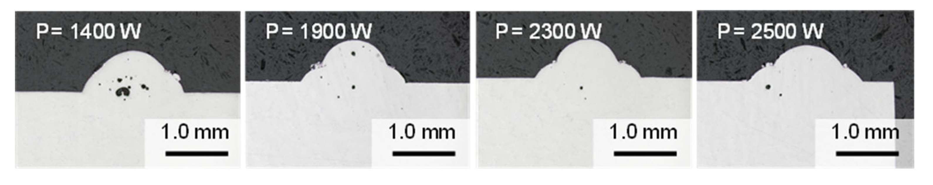
Figure 6.
(a) etched cross-section of the selected DED single-track; (b) point indication of conducted hardness measurement.
Figure 6.
(a) etched cross-section of the selected DED single-track; (b) point indication of conducted hardness measurement.
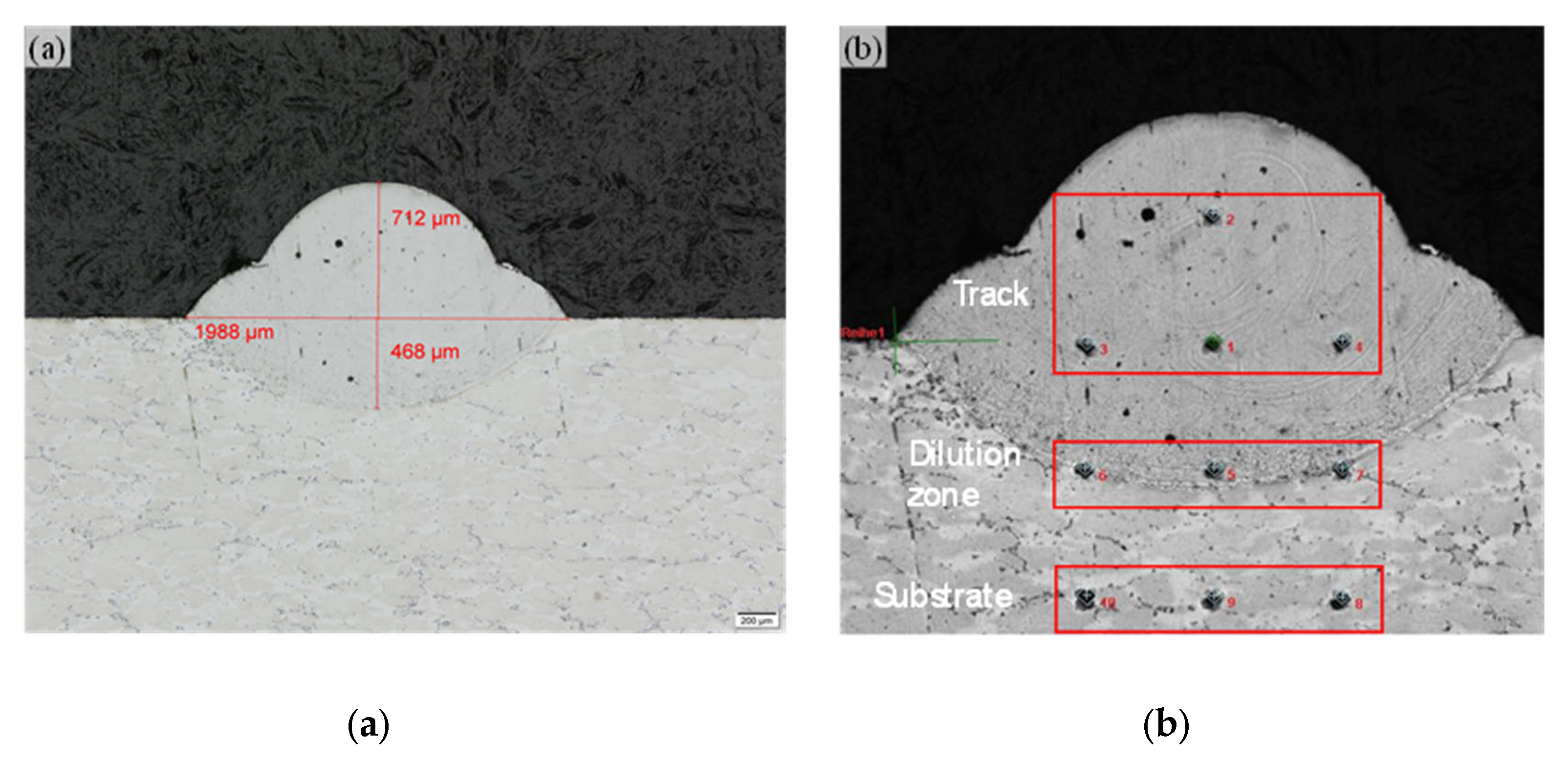
Figure 7.
Cross-sections of Al6061 single-tracks deposited by EHLA.
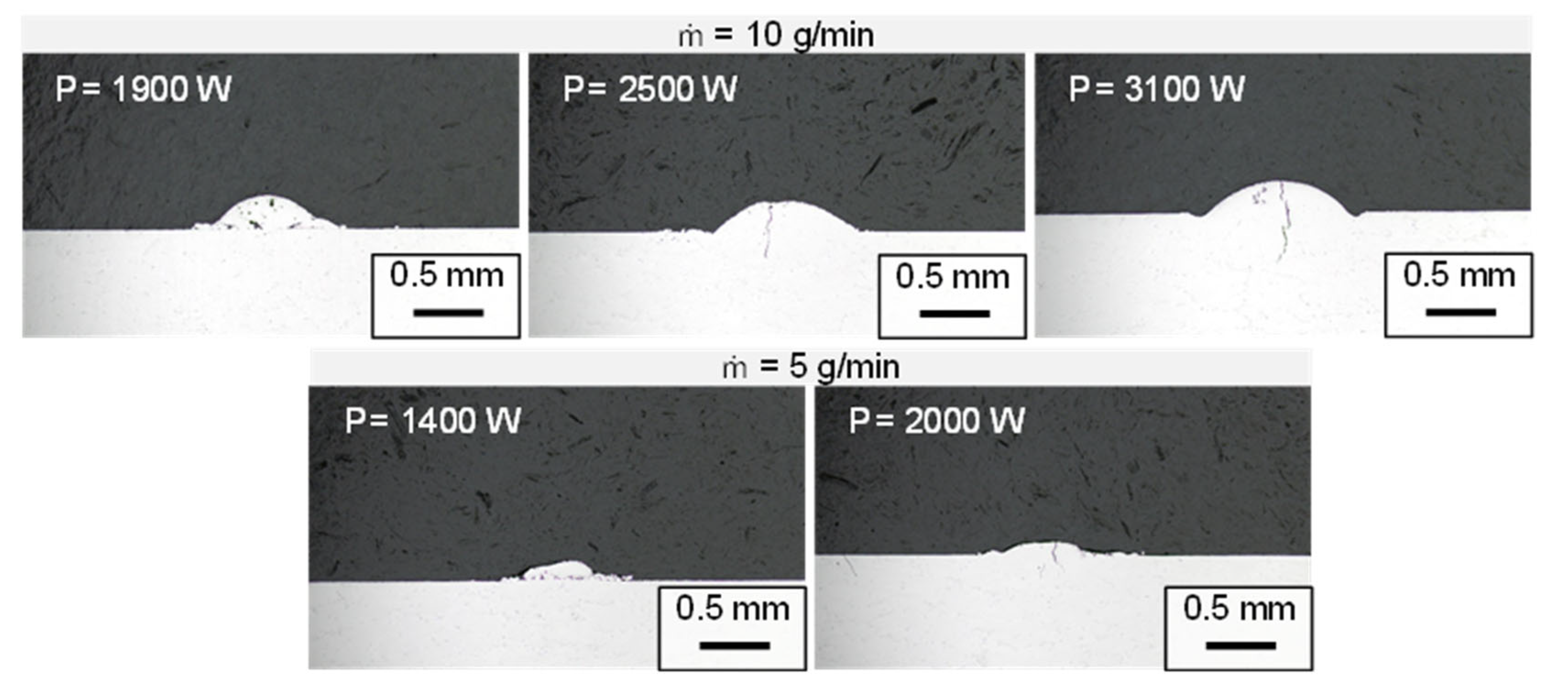
Figure 8.
AlSi10Mg single-tracks deposited by EHLA.
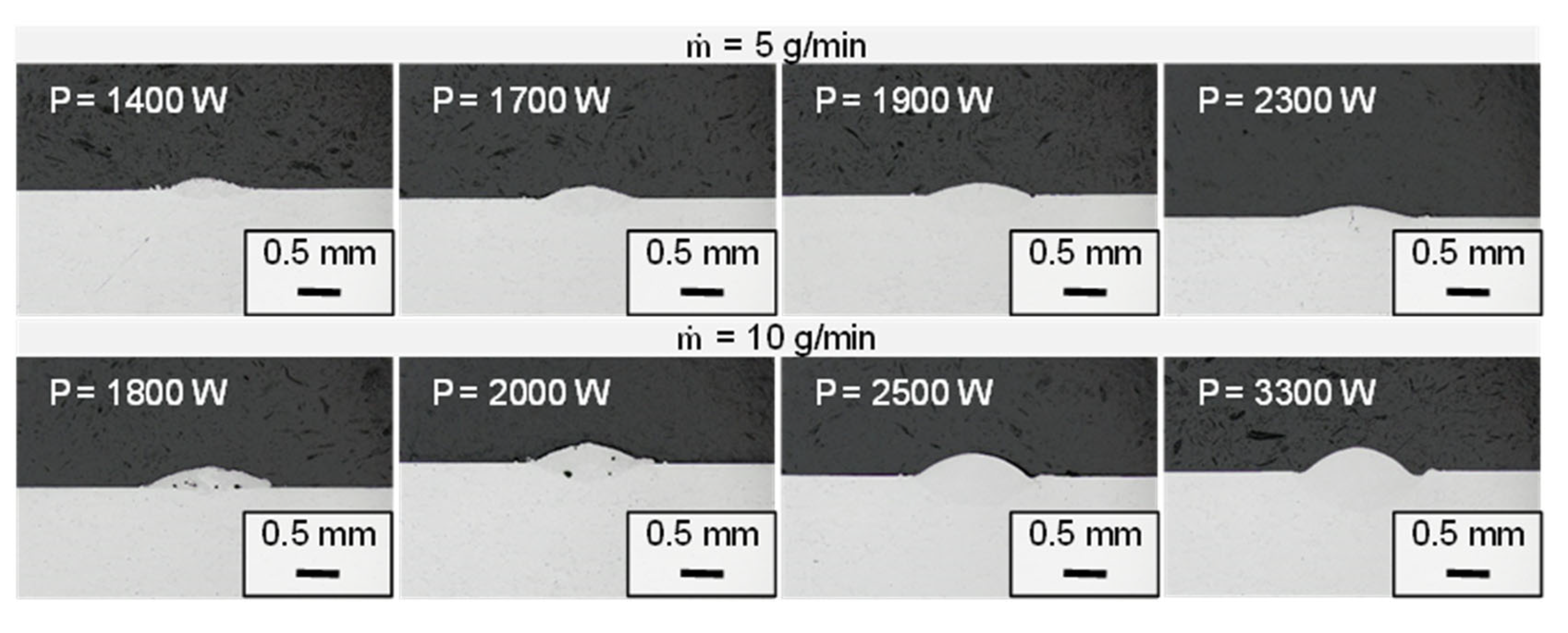
Figure 9.
(a) etched cross-section of the selected EHLA single-track; (b) point indication of conducted hardness measurement.
Figure 9.
(a) etched cross-section of the selected EHLA single-track; (b) point indication of conducted hardness measurement.
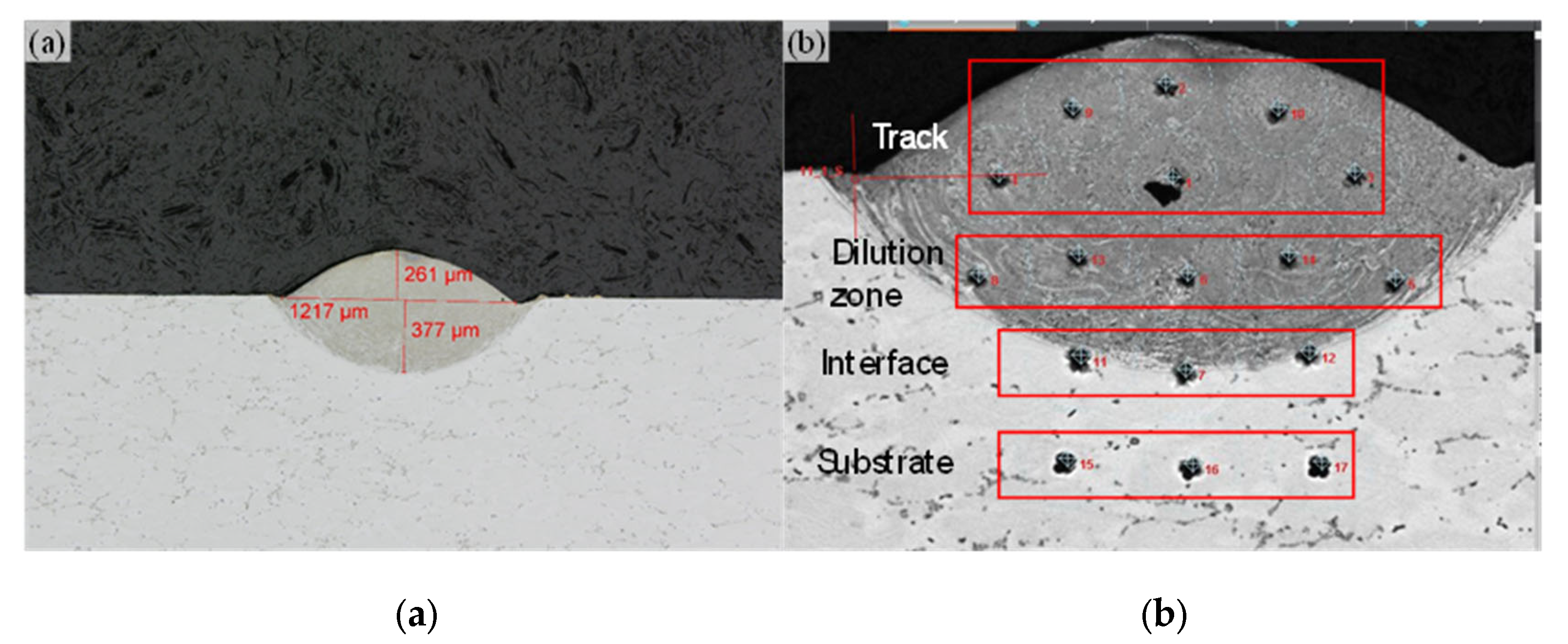
Figure 10.
(a) Cross-sections of DED single layer coating (a) hatch = 40%; (b) hatch = 50%; (c) hatch = 60%.
Figure 10.
(a) Cross-sections of DED single layer coating (a) hatch = 40%; (b) hatch = 50%; (c) hatch = 60%.
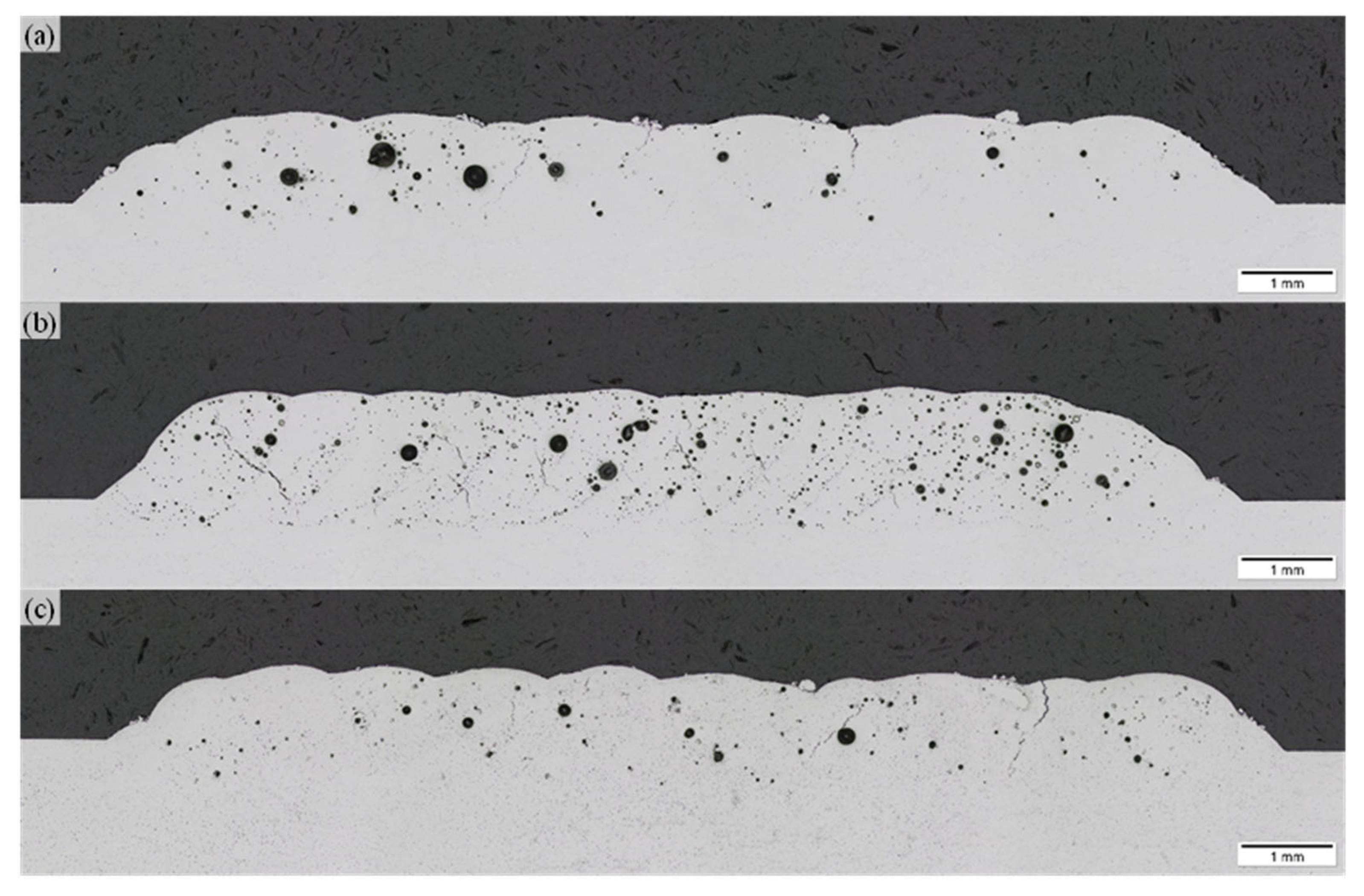
Figure 11.
Cross-section of EHLA single layer coating with 50 % track overlap as hatch distance (a) P = 2500 W; (b) P = 2600 W – etched; (c) P = 2900 W.
Figure 11.
Cross-section of EHLA single layer coating with 50 % track overlap as hatch distance (a) P = 2500 W; (b) P = 2600 W – etched; (c) P = 2900 W.
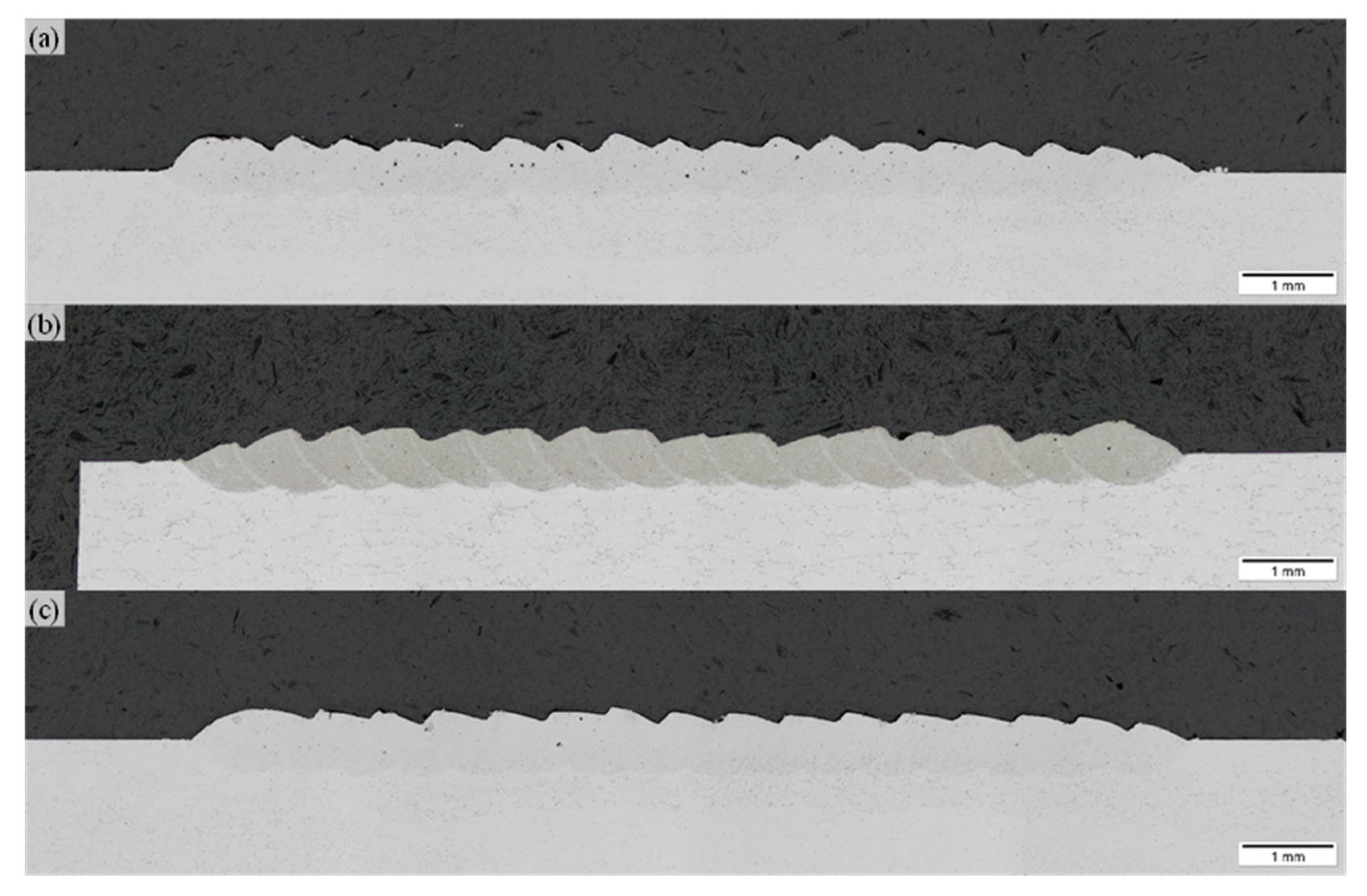
Figure 12.
Point indication of conducted hardness measurement.
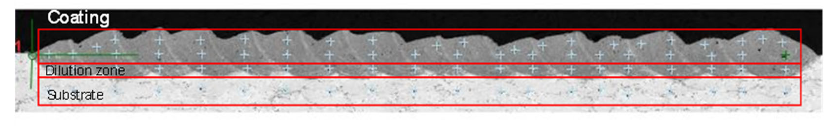
Table 2.
Process parameter combinations for single track analysis.
| dbeam [mm] | V [m/min] | P [W] | ṁ [g/min] |
|---|---|---|---|
| DED | |||
| 1.2 | 2 | 1000 – 2500 | 5 |
| EHLA - Al6061 | |||
| 1.2 | 20 | 900 – 2000 | 5 |
| 1000 – 3100 | 10 | ||
| EHLA – AlSi10Mg4 | |||
| 1.2 | 20 | 800 – 2500 | 5 |
| 1200 – 3300 | 10 | ||
Table 3.
Process parameter combinations for single layer analysis.
| dbeam [mm] | V [m/min] | P [W] | ṁ [g/min] | Hatch [mm] |
|---|---|---|---|---|
| DED – Al6061 | ||||
| 1.2 | 2 | 2300 | 5 | 0.8 |
| 1.0 | ||||
| 1.2 | ||||
| EHLA – AlSi10Mg | ||||
| 1.2 | 20 | 2500 | 10 | 0.60 |
| 2600 | 0.65 | |||
| 2900 | 0.65 | |||
Table 4.
Hardness measurement results of DED single-track.
| Track | Dilution zone | Substrate |
|---|---|---|
| 71 ± 1.9 HV | 77 ± 9.3 HV | 86 ± 3.8 HV |
Table 5.
Hardness measurement results of EHLA single-track.
| Track | Dilution zone | Interface | Substrate |
|---|---|---|---|
| 103 ± 9.3 HV | 89 ± 3.0 HV | 80 ± 4.3 HV | 91 ± 0.3 HV |
Table 6.
Single layer deposition parameters.
| dbeam [mm] | V [m/min] | P [W] | ṁ [g/min] | QC [l/min] | QS [l/min] |
|---|---|---|---|---|---|
| DED – Al6061 | |||||
| 1.2 | 2 | 2300 | 5 | 8 | 12 |
| EHLA – AlSi10Mg4 | |||||
| 1.2 | 20 | 2500 | 10 | 8 | 12 |
| 2600 | |||||
| 2900 | |||||
Table 7.
Hardness measurement result of the EHLA coating .
| Coating | Dilution zone | Substrate |
|---|---|---|
| 91 ± 3.1 HV | 89 ± 4.5 HV | 87 ± 6 HV |
Disclaimer/Publisher’s Note: The statements, opinions and data contained in all publications are solely those of the individual author(s) and contributor(s) and not of MDPI and/or the editor(s). MDPI and/or the editor(s) disclaim responsibility for any injury to people or property resulting from any ideas, methods, instructions or products referred to in the content. |
© 2025 by the authors. Licensee MDPI, Basel, Switzerland. This article is an open access article distributed under the terms and conditions of the Creative Commons Attribution (CC BY) license (http://creativecommons.org/licenses/by/4.0/).
Copyright: This open access article is published under a Creative Commons CC BY 4.0 license, which permit the free download, distribution, and reuse, provided that the author and preprint are cited in any reuse.


