
Submitted:
17 June 2025
Posted:
18 June 2025
You are already at the latest version
Abstract
This study investigates the thermal performance of induction motors powered by multilevel H-bridge inverters using a novel Pulse width Phase Shift Triangle Modulation (PSTM-PWM) technique. Conventional PWM methods introduce significant harmonic distortion, which increases copper and iron losses, causing overheating and reduced motor lifespan. Through experimental testing and comparison with standard PWM techniques (LS-PWM and PS-PWM), the proposed PSTM-PWM demonstrates substantial reduction in harmonic distortion and internal motor losses. A first-order thermal model is used to predict motor temperature, validated with direct thermocouple measurements and infrared thermography. Results indicate that PSTM-PWM technique, particularly at a triangular waveform peak value of 3.5 V, minimizes THD and improves thermal performance, offering a practical and compliant solution for industrial motor drive applications. The modulation order has been set to M=7 in purpose of reducing both the losses in the power inverter and to generate very high voltage pulses (high dV/dt) that can deteriorate the insulation of the motor windings with the time in the induction motor.
Keywords:
Induction motor heating
; multilevel inverter
; harmonic reduction
; thermal modeling
; PWM techniques
; EN50160 compliance
1. Introduction
Induction motors represent one of the most widely used elements in industrial and commercial electrical systems, due to their robustness, efficiency and low maintenance. In recent years, more than 53% of the world's electrical energy consumption has been used by electric motor systems. Since more than 70% of this electrical energy is used by induction motors with low efficiencies [1].
However, the electrical environment in which they operate has changed significantly with the proliferation of nonlinear loads such as power converters, which introduce voltage and current harmonics into the power supply. This harmonic distortion, although often ignored under normal operating conditions, can have severe thermal effects on induction motors, compromising their lifetime, energy efficiency and operational reliability [2].
Harmonics increase stator and rotor copper losses, as well as iron losses due to higher than fundamental frequency harmonics. These increased losses translate directly into increased motor heating, which can exceed the thermal limits of the winding insulation, especially in critical areas such as the winding heads. In addition, low order harmonics (such as 5th and 7th harmonics) generate pulsating torques that further contribute to unwanted mechanical and thermal stresses [3,4].
The thermal impact of harmonics in induction motors is a complex and multifactorial phenomenon, since it depends on the frequency and magnitude of the harmonics, the type of load, the degree of ventilation, and the thermal insulation characteristics of the motor. Although international standards such as IEEE 519 and IEC 60034-17 recommend total harmonic distortion (THD) limits, in many industrial applications these limits are exceeded, resulting in operating conditions outside the rated design [5,6]
The thermal effect can be explained by the following causes:
- Increased losses due to Joule effect (copper losses). Current harmonics have frequencies higher than the fundamental (50 or 60 Hz). As a consequence, the total copper losses increase.
- In addition, these harmonics circulate through both the stator and the rotor (in the form of eddy currents), aggravating the Joule losses in both parts -Additional losses in the iron (magnetic core). The harmonic components of the voltage generate rapid variations of the magnetic flux in the motor core, which increases hysteresis losses, which depend on frequency and magnetization cycle, and eddy current losses, which increase quadratically with frequency. Both mechanisms contribute to additional heat dissipation in the stator core and rotor [9].
- Skin effect. At higher harmonic frequencies, the current tends to concentrate at the periphery of the conductor, reducing the effective cross-section through which the current flows. This increases the apparent resistance of the conductor, and therefore, the resistive losses. This phenomenon is more noticeable in large motors, but also has an impact on small motors under high distortion [10].
- Less effective ventilation due to pulsating torque. Some harmonics, especially those of low odd order (such as 5th or 7th), produce pulsations in the electromagnetic torque that can cause vibrations, resonances and unwanted changes in the speed of the motor fan (if coupled to the shaft). This reduces the efficiency of the motor's cooling system, further raising its temperature [11].
- Localized thermal imbalance. The effect of harmonics is not uniform throughout the motor: certain areas, such as the turn heads or stator slots, can become hotter due to winding geometry and non-uniform loss distribution. This can accelerate insulation deterioration and lead to premature failure [12].
Induction motors are designed to operate within a specific temperature range, defined by the thermal insulation class of their windings. If this range is exceeded, adverse effects are generated that accelerate the aging of the motor and can lead to total failure. The problems caused by overheating in induction motors are as follows:
- Deterioration of the winding insulation. The high temperature degrades the dielectric material covering the stator conductors. It is estimated that for every 10 °C above the limit, the lifetime of the insulation is reduced by half (Montsinger's rule). This can lead to short circuits between turns or between phases, resulting in catastrophic electrical failures [13,14,15,16].
- Efficiency loss. At higher temperature, the resistance of the copper increases, which increases the I²R losses. This reduces the energy efficiency of the motor and increases the electrical consumption [17].
- Rotor damage. Although the rotor is more thermally robust, it also suffers from temperature rise. Mechanical deformation, uneven expansion or weakening of the shaft may also occur [18].
- Bearing and lubrication failures. Excessive heat can degrade lubricating grease, causing premature bearing wear. This leads to vibration, noise and mechanical failure. Decreased thermal performance of the housing [19].
The most critical part of an induction motor in terms of heating is the stator winding, especially the coil heads. These areas are prone to overheating due to accumulation of thermal losses and less efficient heat dissipation. Overheating in these areas can degrade the insulation, which could lead to short circuits between turns and catastrophic motor failure.
In summary, an induction motor should not be heated beyond its thermal capacity because this shortens its life, affects its electrical and mechanical performance, and can lead to critical failures. Keeping the motor within its safe thermal range is essential to ensure its reliability.
Power inverters are widely used to power induction motors because of their ability to control the frequency and amplitude of the applied voltage, which allows speed and torque to be adjusted efficiently. However, the switching operation of these inverters-especially in pulse width modulation (PWM) topologies-inevitably introduces harmonic components into the voltage and current supplied to the motor.
Standard EN50160 defines the characteristics of the voltage supplied by public electricity distribution networks, including limits for harmonic distortion. Although it is not specifically aimed at electric motors, it does establish power quality levels that directly affect their operation and durability. This standard serves as a reference to ensure compatibility between the grid and the equipment connected to it (such as motors). Poor wave quality can cause motors to fail to perform their function properly or suffer premature failure [20].
Unlike an ideal sinusoidal power supply, the output signal of an inverter is composed of a sequence of pulses that approximate a desired sine wave. This nonlinear waveform contains a series of high-frequency harmonics that propagate into the motor [21,22,23]. The voltage harmonics induce harmonic currents in the stator windings, resulting in a number of undesirable effects discussed earlier. In this context, multilevel inverters - such as diode-clamp (NPC)[24,25], flying capacitor (FC)[26] and cascade H-bridge (CHB) inverters [27] - can reduce harmonic distortion, overvoltages and switching losses, which improves both system efficiency and motor life [28,29,30]. This paper presents a modulation technique for multilevel H-bridge inverters that reduces harmonics and achieves lower heating of induction motors. The technique has been compared with classical modulation techniques. The experimental results obtained show the goodness of the PSTM-PWM technique.
The structure of the article will be as follows. Then, a basic thermal model defining the thermal resistance is presented, which will be used to contrast the losses. Chapter 2 presents the peculiarities of the discontinuous modulation technique applied to the reduction of the motor heating. Chapter 3 shows the assembly that has been carried out to feed the motor with the 9-level multilevel converter with H-bridges and with the lowest modulation index of the converter to reduce the switching losses of the power inverter and to generate very high voltage pulses (high dV/dt) that can deteriorate the insulation of the motor windings with the time [7,8]. And finally, Chapter 4 presents the discussion and the conclusions that have been obtained.
Regarding the thermal model, a first order model for induction motors expressed in equation 1 has been chosen, which offers multiple advantages and makes it a practical and efficient tool to evaluate the heating [31,32]. The starting point would be the following equation:
where τ is the thermal time constant (s), θ(t) is the instantaneous motor temperature (°C or K), is the thermal resistance (°C/W) and Ploss, loss power (W), and in the solution of the equation, the thermal time constant will be:
Its mathematical simplicity, based on a single linear differential equation, makes it easy to understand, implement and solve quickly, without requiring complex simulations. In addition, it requires few essential physical parameters, such as thermal resistance and capacitance, which are relatively easy to estimate, thus reducing modeling uncertainty. Although it is a simplified model, it adequately captures the basic heating and cooling dynamics of the motor, including the transient response to changes in losses or load conditions. This feature allows its effective integration into real-time thermal monitoring and control systems, helping to prevent overheating damage. Likewise, the first-order model serves as a basis for more complex and refined developments, maintaining clarity in the thermal analysis. Its low cost, accessibility and general applicability make it a popular choice for most industries, offering the right balance between accuracy and ease of use for thermal evaluation of induction motors.
In the first order thermal model used to represent the thermal behavior of an induction motor, the thermal resistance Rth plays a key role in relating internal losses to temperature rise. Traditionally, this parameter is considered constant to facilitate analytical calculations, however, under real operating conditions, especially in the presence of harmonics in the power supply, this thermal resistance can be significantly affected, altering the accuracy of the model. As the temperature of the motor increases due to these harmonic losses, the thermal properties of the internal materials begin to change. The thermal conductivity of the insulating materials, copper and steel decreases with increasing temperature, reducing the ability of the system to transfer heat to the environment. This phenomenon implies an effective increase in the thermal resistance Rth, although this increase is not evident in static modeling. Additionally, accelerated aging of insulating materials caused by elevated temperatures reduces the overall thermal efficiency of the motor in the long term.
When the motor reaches its thermal steady state the temperature derivative is zero, and the thermal resistance can be calculated using the following expression:
where is the final temperature, is the ambient temperature and Ploss is the total losses.
In this work we are going to analyze how thermal resistance changes as a function of each of the implemented PWM techniques.
The increase in thermal resistance implies that, for the same level of losses, the estimated temperature will be higher, reflecting more critical thermal behavior. If this increase in thermal resistance is not considered in the model, the actual motor temperature may be underestimated, compromising the reliability of the thermal protection system and significantly reducing the life of the motor.
2. PSTM-PWM Technique
The proposed method, called Triangle Phase Shift Modulator (PSTM), is a pulse width modulation (PWM) technique that uses a sine wave as carrier and a triangle wave as modulator. The triangle wave has a higher peak value than the sine wave, which generates periods of no modulation (no switching), causing overmodulation. To keep the number of switching times constant, the carrier frequency is adjusted according to the peak value of the triangle wave. Thus, the same theoretical modulation index M is retained, where M = fp/fm. Figure 1 shows this technique for M = 15.
To obtain the carrier frequency in the PSTM technique, a sine wave (carrier) is compared with a half triangular wave (modulator), resulting in a linear equation describing the modulation. From this comparison, the time instants at which the modulation occurs (t₁ and t₂) are calculated:
where U is the peak value of the triangular and ωₘ its pulsation.
The period for which the modulation lasts is:
The carrier frequency can be calculated by knowing how many pulses must be generated in half a period of the modulating signal, i.e., how many pulses are obtained in π radians. The total number of pulses in half a period is:
The number of pulses in a full period of 2π radians will be twice as many:
Using expression (11), the theoretical modulation order is obtained:
This indicates that the angular frequency of the carrier is not M (efective modulation order) because the modulation is discontinuous. It should be UM times that of the modulating signal, which could be considered as the modulation order necessary to maintain the number of pulses with respect to a continuous modulation technique:
As previously mentioned, increasing the number of switches per period generates more heating in the switches and reduces the efficiency of the inverter. Therefore, it is advisable to work with the lowest possible value of M. For the PSTM-PWM technique, a modulation order M = 7 has been chosen, which complies with EN50160, which sets a maximum THD value of 8 %.
3. Experimental Model of the Multilevel H-Bridge Inverter
To determine which peak values of the triangular wave are the most suitable - that is, producing low total harmonic distortion (THD) and a high RMS value of the fundamental component - a sweep of U values was performed. The objective was to find the value of U that minimizes the THD and maximizes the RMS value of the fundamental, keeping M=7 constant.
Figure 2 shows the THD (total harmonic distortion) value as a function of the peak value of the triangular modulator. The maximum value of the sine wave carrier has been kept at 1V. Minimum THD values are obtained for modulator peak voltages of 1.4 V and 3.5 V.
This technique has been compared with the classical modulation techniques used in H-bridge multilevel inverters: amplitude shift keying (LS-PWM) and phase shift keying (PS-PWM). The results obtained, which are summarized in Table 1, correspond to a modulation order M = 7 and a DC supply voltage Uc=100 V. With these parameters, the proposed technique complies with the requirements established by the EN50160 Standard, while the classical techniques fail to comply with the regulatory limits, due to the presence of harmonic values that exceed the maximum allowed values.
It is also important to note that none of the classical techniques manages to comply with the level of total harmonic distortion (THD) required by the standard for modulation order M=7.
An AEG motor with the following parameters was used to validate the proposed technique: AEG three-phase induction motor Rated voltage: 380V, star connection. Rated power: 0.3 kW. Rated current: 1.65A. Frequency: 50 Hz Rated speed: 1450 rpm. Rated slip: 0.05626, Power factor 0.829, Number of poles = 4, Rated efficiency: 81.56%, Rated torque: 6.82 Nm. Starting current: 5.5 times rated. Starting torque: 2.7 times nominal. Maximum torque: 2.8 times nominal.
For the implementation of the multilevel inverters, the GPT-IGBT module from GUASCH S.ATM was utilized. This module facilitates the construction of an H-bridge using insulated gate bipolar transistors (IGBTs) for motor control applications. It incorporates a three-phase bridge rectifier, a capacitor bank, IGBTs with a forced air-cooled heat sink, opto-isolated drivers, output phase current sensors, a DC-Link current sensor, and a DC-Link voltage sensor. The main electrical specifications include a maximum DC-Link voltage of 750 V and a maximum current output per phase of 32 A.
To generate the control signals for the inverter stages, hardware from National Instruments was employed, specifically the NI9154™ module. A LabVIEW™-based platform was developed to implement various pulse-width modulation (PWM) techniques. Voltage harmonics at the inverter output were measured using three-phase power analyzers, while power quality was assessed with the Chauvin Arnoux™ C.A 8336, which is capable of measuring up to the 50th harmonic. The DC supply voltage (Uc) feeding the H-bridges was set to 100 V. The experimental laboratory setup is illustrated in Figure 3.
4. Experimental Results
For the selection of the measurement location, the motor was pre-warmed for 30 minutes, the hottest points were observed with the thermographic camera and the points of the coil that were the hottest were chosen, one located between the coil passage slot and the coil itself, and the other in the curved part of the coil under the insulator, in addition to the thermocouple that measures the internal ambient temperature Figure 6.Authors should discuss the results and how they can be interpreted from the perspective of previous studies and of the working hypotheses. The findings and their implications should be discussed in the broadest context possible. Future research directions may also be highlighted.
The motor was supplied with a voltage of 380 V RMS of the fundamental harmonic in star mounting for all techniques. The load consisted of an eddy current fed eddy current brake to adjust the power consumed to 200 W. The total power consumed by the machine was also measured to evaluate the power losses of each technique. A controlled ambient temperature of 25 ºC was assumed for all techniques.
For an accurate evaluation of the heating in an induction motor, it is essential to measure the temperature directly in the stator windings. This can be achieved by means of integrated temperature sensors such as thermocouples that provide accurate readings of the internal temperature of the motor.
It should be noted that the accuracy of thermocouples can range from ±0.5 °C to ±2.0 °C, depending on factors such as the type of thermocouple, the quality of the mounting, and the calibration of the acquisition system.
During the process, care was taken to keep the experimental conditions constant: the sensor was fixed in a stable manner to ensure good thermal contact, and a uniform acquisition frequency was maintained for all measurements. These precautions minimized the occurrence of systematic errors associated with variations in positioning or reading times. To evaluate the consistency and stability of the measurements under controlled conditions, 15 consecutive measurements were taken at the same sampling point.
From the data obtained, the basic statistical parameters were calculated: the arithmetic mean as a representative value of the measured temperature, and the standard deviation as an estimate of the dispersion of the readings. Under stable conditions and with good mounting, the standard deviation obtained was consistent with what is expected for this type of sensor, being located in a range of approximately ±0.3 °C to ±0.6 °C. These values reflect both the sensitivity of the sensor and small local thermal variations of the system under study.
The temperature of the outside of the motor and windings were also measured using a thermographic camera. It is important to note that measuring the temperature on the external surface of the motor does not provide accurate indication of the internal temperature of the windings, since the casing can be significantly cooler than the inside of the motor.
From the tests, the thermal resistance was calculated for each of the techniques using equation 2. Table 2 below shows the average values of the 15 temperature measurements made and, therefore, the calculated values of these thermal resistances.
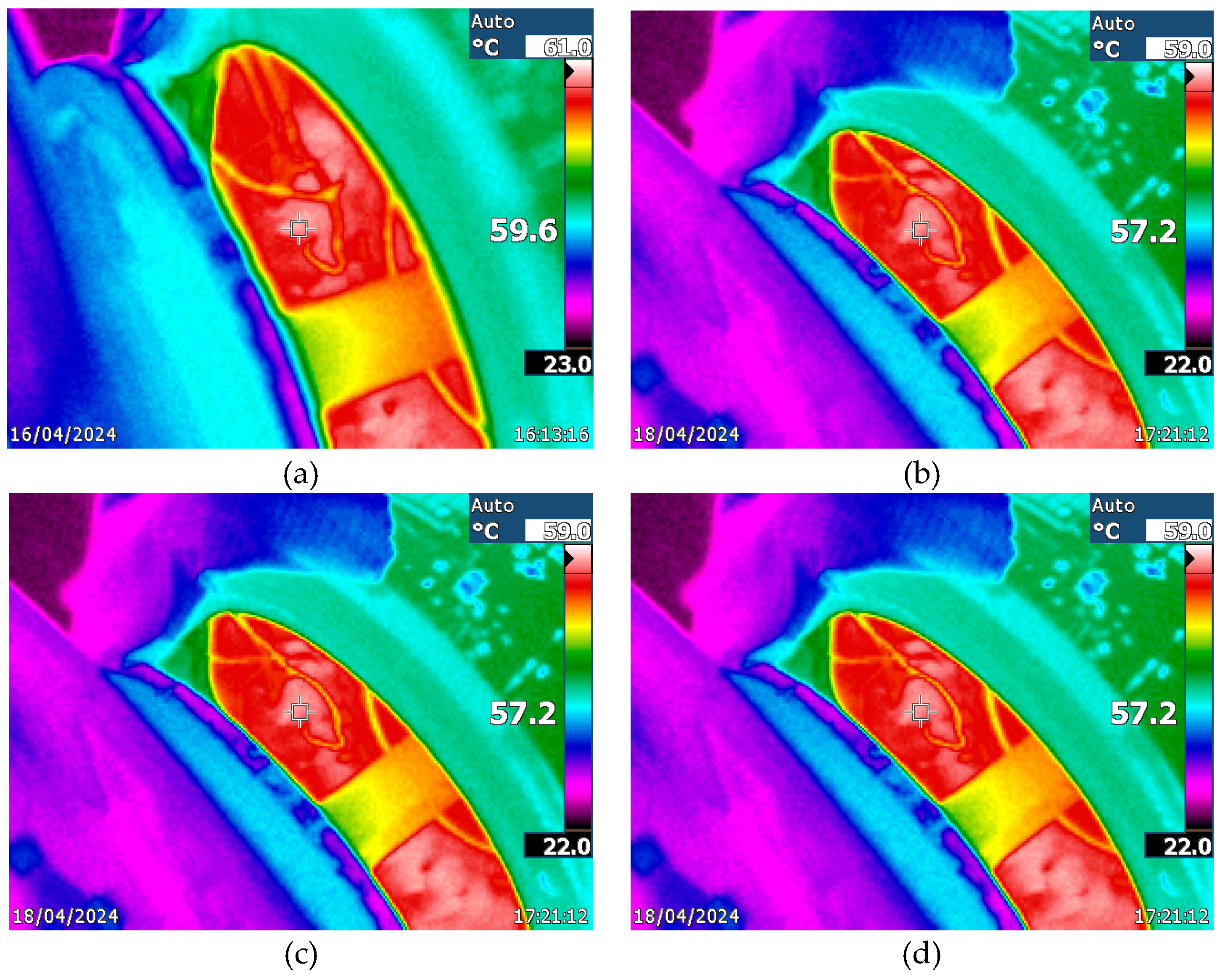
With the proposed technique, losses are reduced due to the lower harmonic content. In addition, the thermal resistance is higher, so the motor heats up less. The following figures show the images obtained with the thermographic camera of the techniques tested. There is a difference between the temperatures provided with the measurements made with the thermocouples and those provided with the thermographic camera, because the thermographic camera measures areas and not specific points, so it can have errors of ± 1 degree. The reading of a thermocouple is more accurate. But in the test carried out there is a correlation between the techniques used and the measurements both with the thermographic camera and the thermocouples. Of the measurements made, those corresponding to the thermocouples are taken as valid. The following graph shows the measurements with the thermographic camera of the motor with the techniques used: (a) LS-PWM, (b) PS-PWM, (c) PSTM-PWM V=1.4, (d) PSTM-PWM V=3.5.
Figure 7.
Imagen de las termografías de las Técnicas: (a) LSPWM, (b) PSPWM, (c) PSTM V=1.4 y (d) PSTM V=3.5.
Figure 7.
Imagen de las termografías de las Técnicas: (a) LSPWM, (b) PSPWM, (c) PSTM V=1.4 y (d) PSTM V=3.5.
Subsequently, and to contrast the goodness of the technique, we proceeded to increase the motor load by increasing the power consumed by the brake by 10% with the proposed PSTM-PWM technique with V=3.5, since it showed the best thermal behavior. The losses calculated by the difference between the input power and the power consumed by the eddy current brake was 17.3 W. With this measured power loss data and using equation (3) together with the thermal resistance value from Table 2 corresponding to the technique used, the temperature should be 58.2 degrees Celsius.
After reaching the regime temperature at 4 times its thermal time constant (5552 seconds), the new temperature measurements were carried out. The average value of the 15 measurements made with the thermocouple at the head of the coils gave a value of 58.1 degrees Celsius. Figure 8 shows the measurement made with the thermographic camera gives a maximum value of 58.0 degrees Celsius.
5. Discussion and Conclusions
This paper has shown that harmonics generated by power inverters have a significant impact on the thermal behavior of induction motors, increasing their internal losses, mainly due to the Joule effect, iron losses and phenomena such as the pellicular effect. These additional losses result in an increase in temperature, especially in critical areas such as the stator coil heads, which compromises the life of the insulation and, therefore, the reliability and durability of the motor.
In order to mitigate these effects, a new PSTM-PWM (Pulse width Phase Shift Triangle Modulation) pulse width modulation technique has been implemented and experimentally evaluated, applied in an H-bridge type multilevel inverter. This technique is distinguished by the use of a sinusoidal signal as carrier and a triangular signal with overmodulation as modulator, allowing to effectively reduce the harmonic content of the inverter output signal. The modulation order parameter was kept constant at M = 7, in order to keep the number of switching operations as low as possible and to comply with the requirements of the EN50160 standard, as opposed to conventional techniques that do not comply with it. It is true that this is not mandatory, but it is recommended. In addition, to minimize power inverter losses and reduce the generation of high-voltage pulses with steep voltage transitions (high dV/dt), which can lead to long-term degradation of the insulation in induction motor windings, the modulation order was set to M = 7.
During laboratory tests, three modulation techniques were compared: LS-PWM, PS-PWM and two configurations of the proposed PSTM-PWM technique (with peak values of the triangular signal U = 1.4 V and U = 3.5 V). To ensure homogeneous conditions, the AEG motor used was subjected to a constant load of 200 W using a Foucault brake, and with a supply voltage of 380 V RMS corresponding to the fundamental harmonic. Temperatures were measured at the winding heads using thermocouples. Temperatures were also measured with a thermographic camera.
The results indicated that the PSTM-PWM technique, especially with U equal to 3.5V, achieved a significant reduction in the internal temperature of the motor compared to the classical techniques. The average temperature recorded in the winding was 55.3°C with this technique, compared to 61.1°C obtained with LS-PWM, which represents a clear reduction in thermal stress. Also, lower internal losses were observed (15.9 W for PSTM-PWM versus 31.2W for LS-PWM), which was reflected in an increase of calculated thermal resistance, confirming that the motor heats up less under this configuration.
To validate the robustness of the first-order thermal model used in this study, an additional test was performed by increasing the motor load by 10% (up to 220W), maintaining the PSTM-PWM technique with U equal to 3.5V. The model predicted a final temperature of 58.2°C, a value that was practically confirmed by the experimental measurement with thermocouple (58.1°C) and by the thermographic camera (58.0°C), which evidences the validity of the proposed model for real-time thermal estimations.
In summary, the experimental results confirm that the PSTM-PWM technique not only meets the regulatory requirements in terms of total harmonic distortion (THD), but also allows a remarkable improvement in the thermal behavior of induction motors fed by multilevel inverters. This implies a reduction in motor heating, reduced insulation aging, higher energy efficiency and a possible extension of the equipment lifetime. Therefore, it is concluded that the PSTM-PWM technique constitutes an effective and practical technical alternative to conventional modulation strategies, especially in industrial applications where power quality and thermal reliability are critical factors.
Author Contributions
A.R.G. conceptualization and methodology, F.P.H., J.H.L. and M.M.G. Simulation and Data collection, A.R.G., F.P.H., J.H.L. and M.M.G hardware implementation, A.R.G. writing—original draft preparation A.R.G., F.P.H., J.H.L. and M.M.G validation, writing—review and editing. F.H.P. funding acquisition. the authors have read and agree with the final version of the manuscript.
Data Availability Statement
The data are contained in this paper.
Acknowledgments
During the preparation of this manuscript/study, the authors used ChatGPT to improve the English text. The authors have reviewed and edited the output and take full responsibility for the content of this publication.
References
- Muñoz Tabora, J.; et al. Voltage harmonic impacts on electric motors: A comparison between IE2, IE3 and IE4 induction motor classes. Energies 2020, 13, 3333. [Google Scholar] [CrossRef]
- NEMA MG 1 – "Motors and Generators" National Electrical Manufacturers Association 1300 North 17th Street, Suite 1752, Rosslyn, VA 22209. www.nema.org, URL: https://www.weg.net.
- Umesh, H.; Rashmi, K. Causes and Effect of Inverter Harmonics. In book Current Perspective to Physical Science Research 6, Prof. Shi-Hai Dong, BP International, Mexico D.F. 2024, pp. 70-89. [CrossRef]
- Horia Gheorghe, B.; et al. Harmonics consequences on drive systems with induction motor. Applied Sciences 2020, 10, 1528. [Google Scholar] [CrossRef]
- Gnaciński, P.; et al. Induction motors under voltage fluctuations and power quality standards. IEEE Transactions on Energy Conversion 2023, 39, 1255–1264. [Google Scholar] [CrossRef]
- Fuchs, Ewald F., Are harmonic recommendations according to IEEE-519 and CEI/IEC 555 too restrictive? Frontiers of power conference. Engineering Energy Laboratory, Oklahoma State University; 1998, 2002. p. IV-IV.
- Mirza, A.Y.; et al. Motor stator insulation stress due to multilevel inverter voltage output levels and power quality. Energies 2022, 15, 4091. [Google Scholar] [CrossRef]
- Saeed, M.; et al. Insulation Condition Assessment in Inverter-Fed Motors Using the High-Frequency Common Mode Current: A Case Study. Energies 2024, 17, 470. [Google Scholar] [CrossRef]
- Debruyne, C.; Vandevelde, L.; Desmet, J. Harmonic effects on induction and line start permanent magnet machines. Energy Efficiency in Motor Driven Systems, EEMODS, 2013. [Google Scholar]
- Fatima, A.; et al. Modelling of Inductances Considering Bar Harmonics and Temperature to Accurately Predict Output Torque of an Induction Motor. IEEE Access 2024. [CrossRef]
- Abramov, B.I.; et al. Electric drives of mining installations. Russian Electrical Engineering 2017, 88, 159–165. [Google Scholar] [CrossRef]
- Donolo, P.; et al. Voltage unbalance and harmonic distortion effects on induction motor power, torque and vibrations. Electric power systems research 2016, 140, 866–873. [Google Scholar] [CrossRef]
- De abreu, J.P.G.; Emanuel, A.E. Induction motor thermal aging caused by voltage distortion and imbalance: loss of useful life and its estimated cost, 2001 IEEE Industrial and Commercial Power Systems Technical Conference. Conference Record (Cat. No. 01CH37226). IEEE, 2001. p. 105-114. [CrossRef]
- Husach, S. Python-based Induction Motors Monitoring and Lifetime Estimation System. IEEE International Conference on Modern Electrical and Energy Systems (MEES). IEEE, 2021, 1-4. [CrossRef]
- Rusu-Zagar, C.; et al. Method for estimating the lifetime of electric motors insulation, 2013 8th International Symposium On Advanced Topics In Electrical Engineering (ATEE). IEEE, 2013. p. 1-6. [CrossRef]
- Muxiri, A.; et al. Thermal analysis of an induction motor subjected to inter-turn short-circuit failures in the stator windings. 2019 International Conference on Industrial Engineering, Applications and Manufacturing (ICIEAM). IEEE, 2019. p. 1-5. [CrossRef]
- Singh, G.K. A research survey of induction motor operation with non-sinusoidal supply wave forms. Electric power systems research 2005, 75, 200–213. [Google Scholar] [CrossRef]
- Beleiu, H.G.; et al. Harmonics consequences on drive systems with induction motor. Applied Sciences 2020, 10, 1528. [Google Scholar] [CrossRef]
- Zhu, W.; et al. A review of modeling and mitigation techniques for bearing currents in electrical machines with variable-frequency drives. IEEE Access 2022, 10, 125279–125297. [Google Scholar] [CrossRef]
- Piotr, G.; et al. Induction motors under voltage fluctuations and power quality standards. IEEE Transactions on Energy Conversion 2023, 39, 1255–1264. [Google Scholar] [CrossRef]
- Dugan, R.C.; McGranaghan, M.F.; Santoso, S.; Beaty, H.W. Electrical Power Systems Quality, 2nd ed.; McGraw Hill Companies: New York, NY, USA, 2004. [Google Scholar]
- Rata, G.; Rata, M.; Graur, I.; Milici, D.L. Induction Motor Speed Estimator Using Rotor Slot Harmonics. Adv. Electr. Comput. Eng. 2009, 9, 70–73. [Google Scholar] [CrossRef]
- Beleiu, H.G.; Maier, V.; Pavel, S.G.; Birou, I.; Pică, C.S.; Dărab, P.C. Harmonics Consequences on Drive Systems with Induction Motor. Appl. Sci. 2020, 10, 1528. [Google Scholar] [CrossRef]
- Dargahi, V.; Abarzadeh, M.; Corzine, K.A.; Enslin, J.H.; Sadigh, A.K.; Rodriguez, J.; Blaabjerg, F.; Maqsood, A. Fundamental Circuit Topology of Duo-Active-Neutral-Point-Clamped and Duo-Neutral-Point-Piloted Multilevel Converters. IEEE Journal of Emerging and Selected Topics in Power Electronics 2019, 7, 1224–1242. [Google Scholar] [CrossRef]
- Rodriguez, J.; Bernet, S.; Steimer, P.K.; Lizama, I.E. A survey on neutral-point-clamped inverters. IEEE Trans. Ind. Electron. 2010, 57, 2219–2230. [Google Scholar] [CrossRef]
- Hasegawa, I.; Kondo, T.; Kodama, T. Experiment of five-level BTB-system with common flying capacitors. 8th IET International Conference on Power Electronics, Machines, and Drives, PEMD, 2016. [Google Scholar]
- Malinowski, M.; Gopakumar, K.; Rodriguez, J.; Perez, M.A. A survey on cascaded multilevel inverters. IEEE Trans. on Ind. Electron 2010, 57, 2197–2206. [Google Scholar] [CrossRef]
- Leon, J.I.; Vazquez, S.; Franquelo, L.G. Multilevel converters: Control and modulation techniques for their operation and industrial applications. Proc. IEEE. 2017, 105, 2066–2081. [Google Scholar] [CrossRef]
- Aslam, A.W.; et al. Traditional and Hybrid Topologies for Single-Three-Phase Transformerless Multilevel Inverters. Electronics 2024, 13, 4058. [Google Scholar] [CrossRef]
- Choudhury, S.; Bajaj, M.; Dash, T.; Kamel, S.; Jurado, F. Multilevel Inverter: A Survey on Classical and Advanced Topologies, Control Schemes, Applications to Power System and Future Prospects. Energies 2021, 14, 5773. [Google Scholar] [CrossRef]
- Nogal, Ł.; et al. The laboratory analysis of the thermal processes occurring in low-voltage asynchronous electric motors. Energies 2021, 14, 2056. [Google Scholar] [CrossRef]
- Moreno, J.F.; Hidalgo, F.P.; Martinez, M.D. Realization of tests to determine the parameters of the thermal model of induction machine. Proc. IEE, Electrical Power Appl. 2001, 148, 393–307. [Google Scholar] [CrossRef]
Figure 1.
(a) Modulating (sine) and carrier (triangular) waves, (b) Modulated wave.
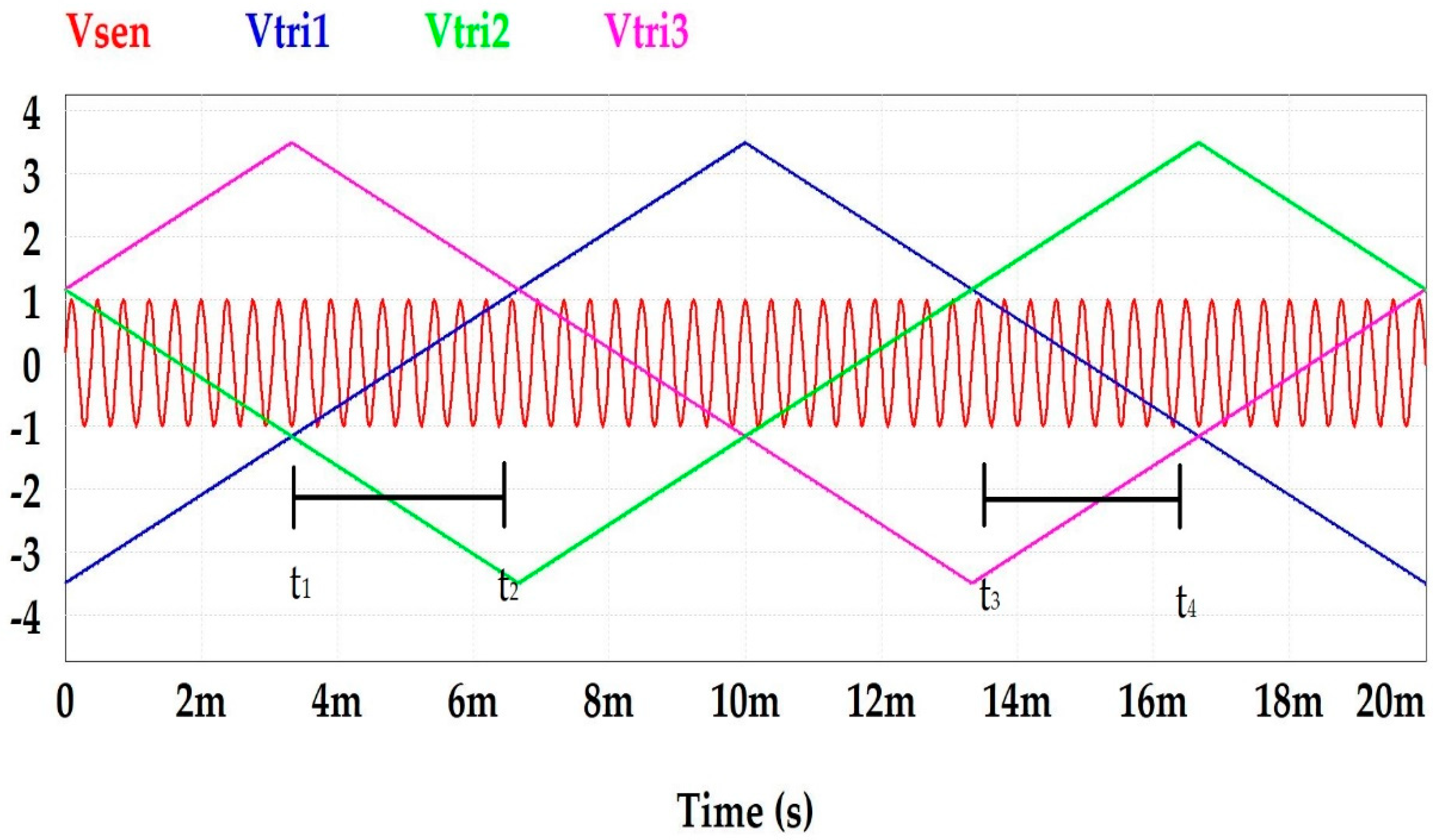
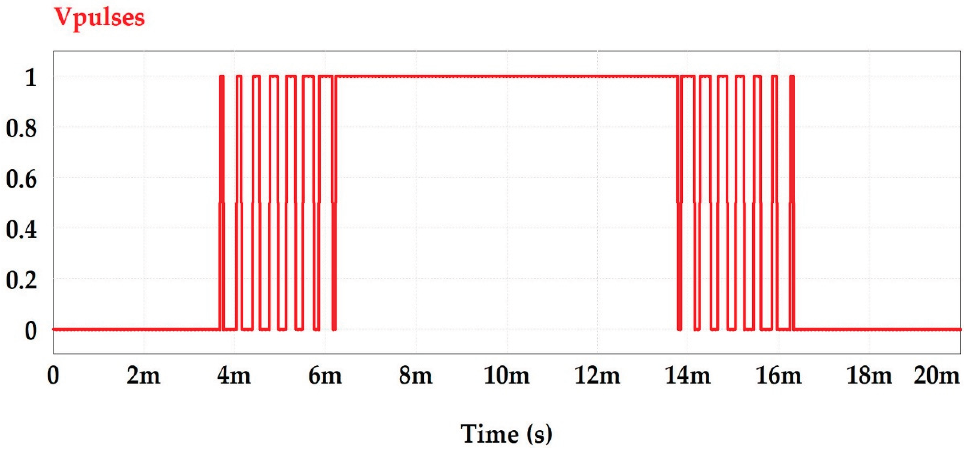
Figure 2.
Total harmonics distortion versus triangular modulator amplitude.
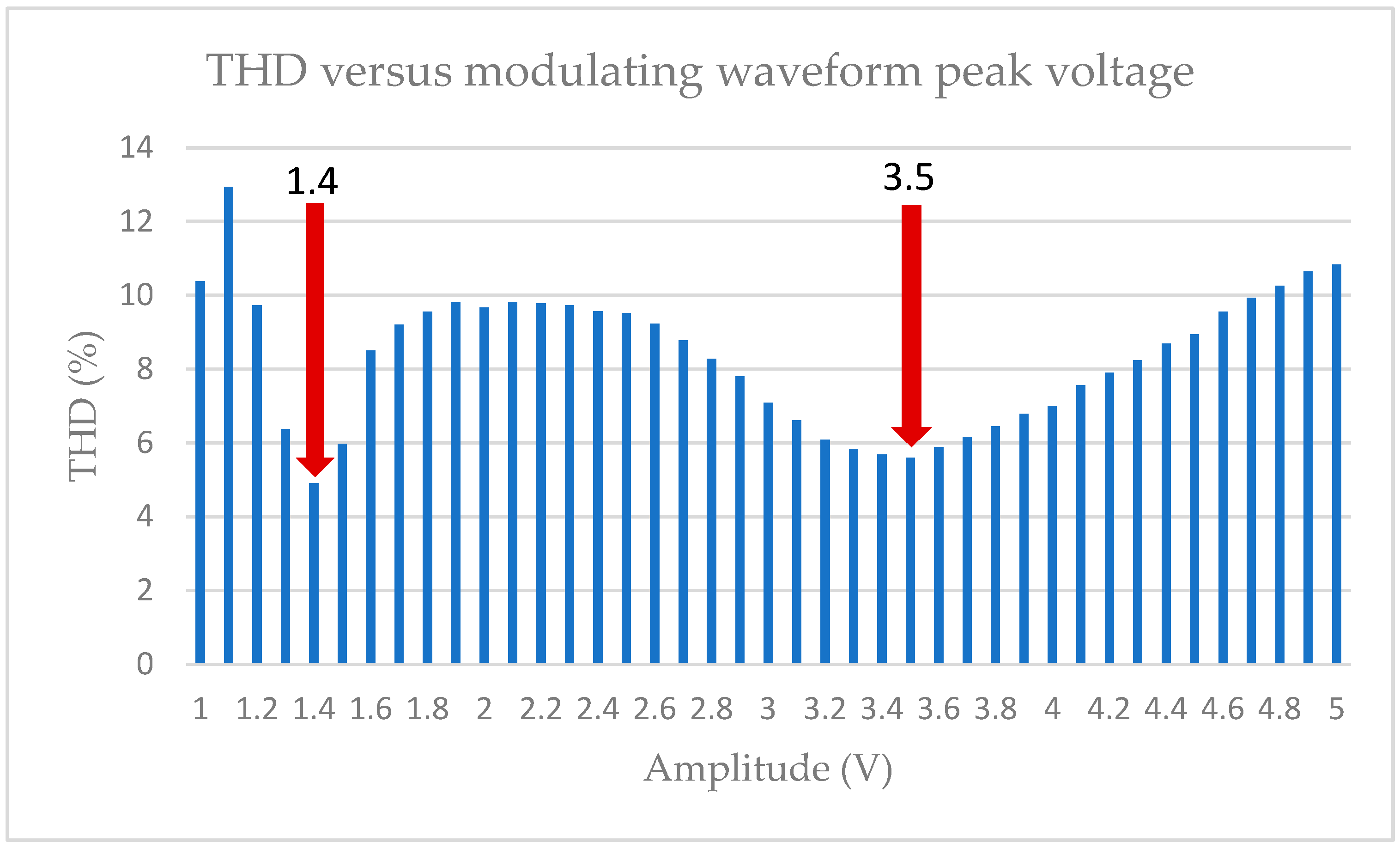
Figure 3.
Experimental laboratory setup. Control, H-bridge, Measurements and motor.
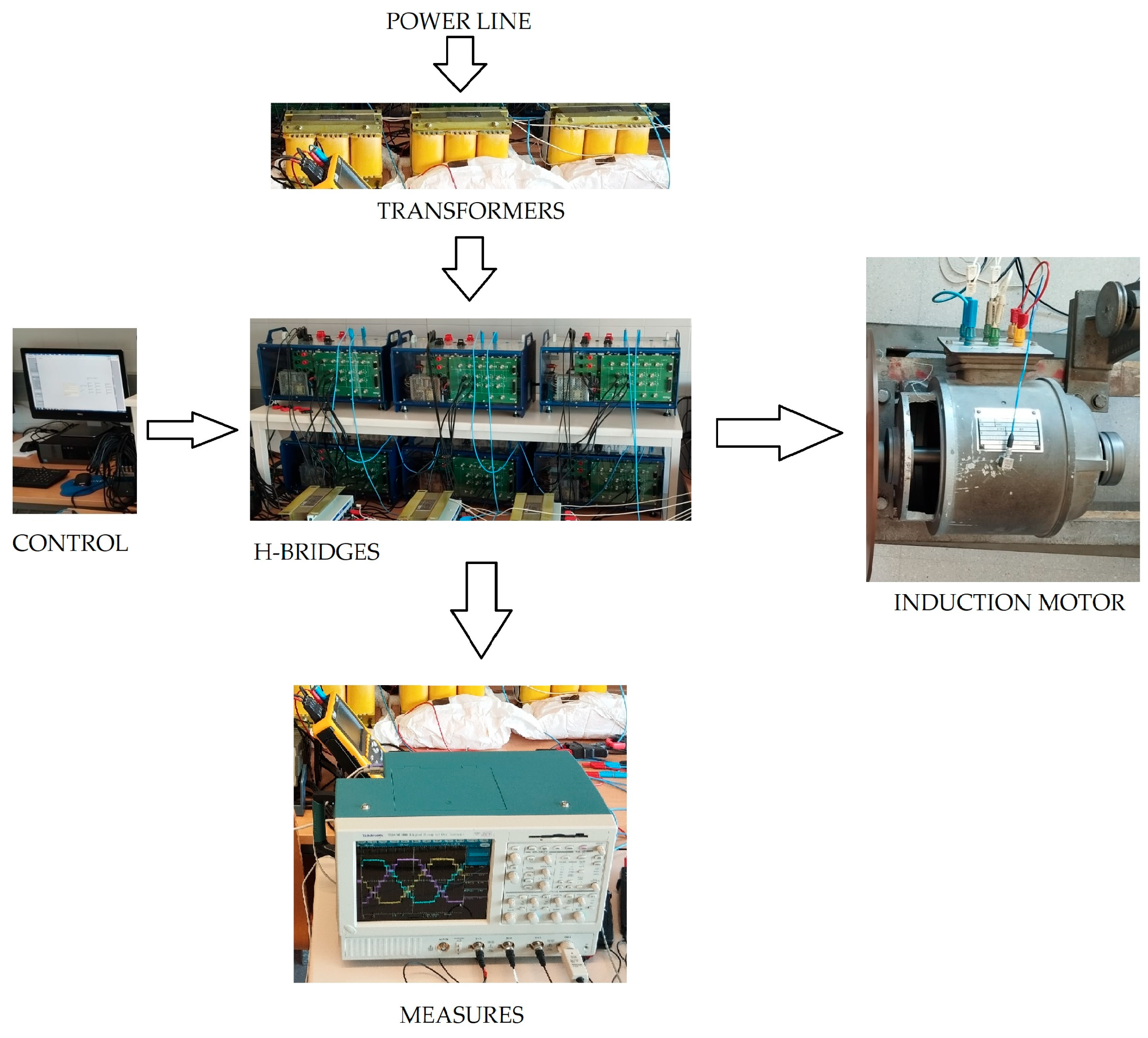
Figure 4.
Oscillograms of PWM techniques: (a) LS-PWM, (b) PS-PWM.
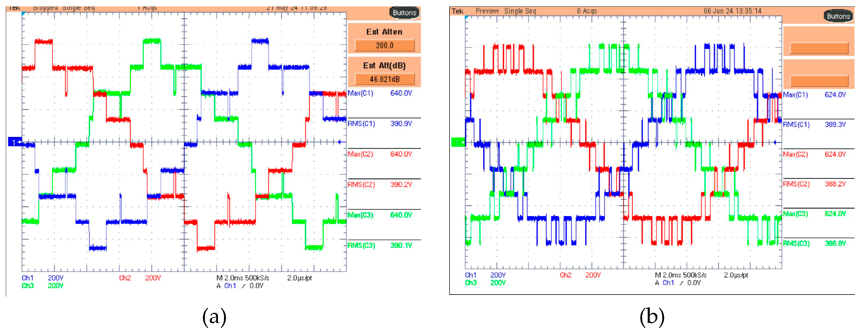
Figure 5.
Oscillograms of PWM techniques (a) PSTM-PWM V=1.4, (b) PSTM-PWM V=3.5.
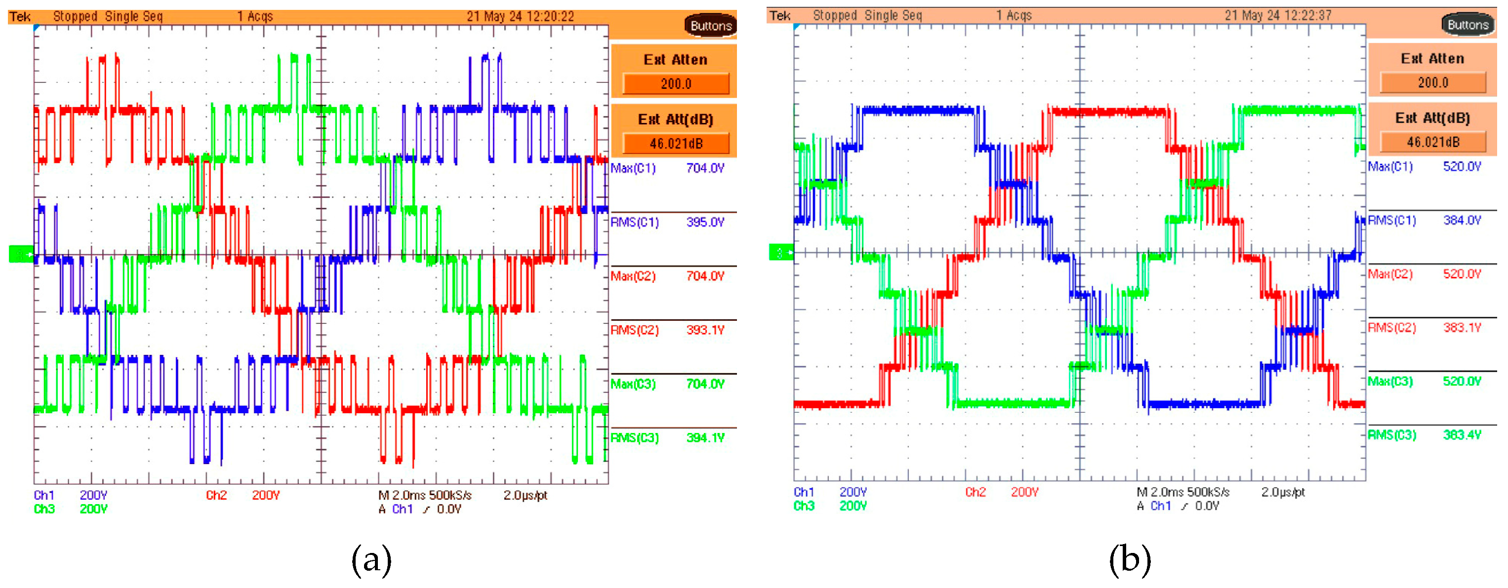
Figure 6.
Data acquisition module for thermocouples and Foucault brake connected to the motor.
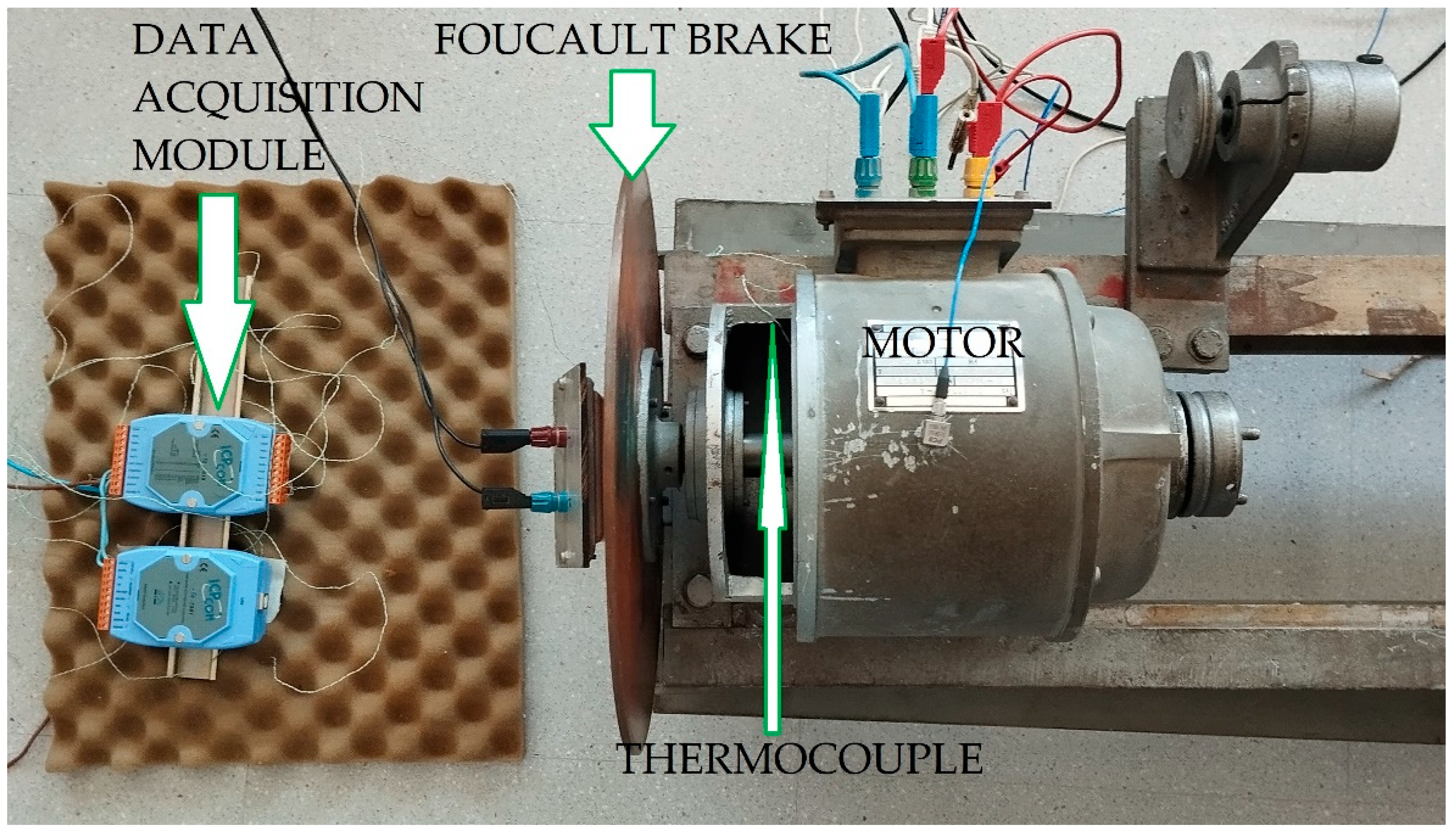
Figure 8.
Thermography image of the PSTM V=3.5 Technique with 10% more load.
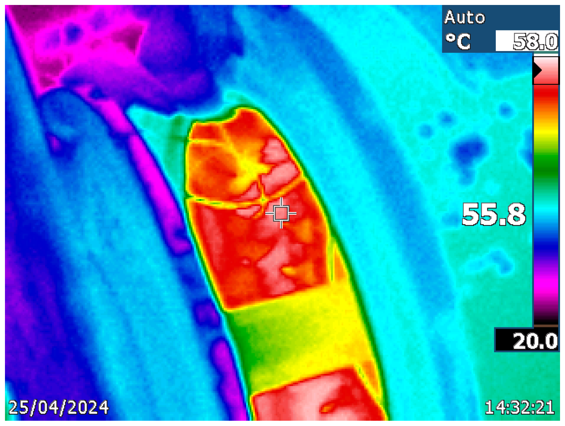

Table 1.
Harmonic levels (%) of different modulation techniques with multilevel inverter with M=7.
| Harm. |
Standard EN50160 (%) |
LS-PWM (%) |
PS-PWM (%) |
PSTM-PWM V=1.4 (%) |
PSTM-PWM V=3.5 (%) |
|---|---|---|---|---|---|
| 1 | 100 | 100 | 100 | 100 | |
| 2 | 2.000 | 0.000 | 0.000 | 0.005 | 0.010 |
| 3 | 5.000 | 3.789 | 0.193 | 0.059 | 0.134 |
| 4 | 1.000 | 0.000 | 0.000 | 0.002 | 0.004 |
| 5 | 6.000 | 3.438 | 0.074 | 0.819 | 1.628 |
| 6 | 0.500 | 0.000 | 0.000 | 0.007 | 0.000 |
| 7 | 5.000 | 4.195 | 0.176 | 4.122 | 4.001 |
| 8 | 0,500 | 0.000 | 0.000 | 0.006 | 0.005 |
| 9 | 1.500 | 3.832 | 0.037 | 0.074 | 0.166 |
| 10 | 0.500 | 0.000 | 0.000 | 0.003 | 0.004 |
| 11 | 3.500 | 6.652 | 0.105 | 1.656 | 1.741 |
| 12 | 0.500 | 0.000 | 0.000 | 0.007 | 0.000 |
| 13 | 3.000 | 3.677 | 0.030 | 0.737 | 0.782 |
| 14 | 0.500 | 0.000 | 0.000 | 0.006 | 0.003 |
| 15 | 0.500 | 1.722 | 0.051 | 0.070 | 0.282 |
| 16 | 0.500 | 0.000 | 0.000 | 0.004 | 0.003 |
| 17 | 2.000 | 4.126 | 0.196 | 1.347 | 1.562 |
| 18 | 0.500 | 0.000 | 0.000 | 0.006 | 0.000 |
| 19 | 1.500 | 0.160 | 0.161 | 0.108 | 0.337 |
| 20 | 0.500 | 0.000 | 0.000 | 0.008 | 0.001 |
| 21 | 0.500 | 4.876 | 5.017 | 0.048 | 0.434 |
| 22 | 0.500 | 0.000 | 0.000 | 0.009 | 0.002 |
| 23 | 1.500 | 1.715 | 11.772 | 1.007 | 1.290 |
| 24 | 0.500 | 0.000 | 0.000 | 0.008 | 0.000 |
| 25 | 1.500 | 4.761 | 0.090 | 0.412 | 0.627 |
| Fund. Value RMS | 250,51 | 243.95 | 221,32 | 295.57 | |
| THD25 (%) | 8 | 13.62 | 12.83 | 4.89 | 5.59 |
Table 2.
Temperature, time to steady state, loss and thermal resistance for different techniques.
|
Temperature (° C) |
Time (s) |
Losses (W) |
Rth (° C/W) |
|
|---|---|---|---|---|
| LSPWM | 61,1 | 6332 | 31,2 | 1,15705128 |
| PSPWM | 59,2 | 5570 | 25,8 | 1,3255814 |
| PSTM V=1.4 | 56,2 | 5541 | 16,2 | 1,92592593 |
| PSTM V=3.5 | 55,3 | 5530 | 15,9 | 1,90566038 |
Disclaimer/Publisher’s Note: The statements, opinions and data contained in all publications are solely those of the individual author(s) and contributor(s) and not of MDPI and/or the editor(s). MDPI and/or the editor(s) disclaim responsibility for any injury to people or property resulting from any ideas, methods, instructions or products referred to in the content. |
© 2025 by the authors. Licensee MDPI, Basel, Switzerland. This article is an open access article distributed under the terms and conditions of the Creative Commons Attribution (CC BY) license (http://creativecommons.org/licenses/by/4.0/).
Copyright: This open access article is published under a Creative Commons CC BY 4.0 license, which permit the free download, distribution, and reuse, provided that the author and preprint are cited in any reuse.


