
Submitted:
13 June 2025
Posted:
17 June 2025
You are already at the latest version
Abstract
Dragonfly is one the most agile insects on the earth and has excellent flight performance in the low Reynold number flow conditions. This study aims to develop biocomposite film-based flapping wings for micro air vehicles (MAVs), inspired by the dragonfly (Pantala flavescens). Using chitosan polymer and waste wood microparticles wing composite material is developed. Biocomposite films are fabricated by varying the chitosan content from 2.0 to 2.5 wt/v% and reinforcing them with wood microparticles ranging from 0.5 to 2.0 wt/v%. The films are characterized through tensile testing, dynamic mechanical analysis, natural frequency measurement, and water contact angle testing. The optimal performance is observed for the films reinforced with 1.5 wt% wood particles and 2.5 wt% chitosan, which shows a tensile strength of 48.7 MPa, tensile modulus of 1410 MPa, storage modulus of 5090 MPa, and damping factor of 0.12. The optimized bio-composite film is also subjected to structural dynamic analysis both experimentally, using Digital Image Correlation (DIC), and computationally, using Abaqus. The results demonstrate that the developed biocomposite films possess significant potential for application as flapping wings in MAVs inspired by dragonfly flight.
Keywords:
bioinspired
; dragonfly wings
; MAVs
; bio-composites
; DIC
1. Introduction
Nature is an unparalleled laboratory, offering an extensive repository of efficient solutions to complex scientific and technical problems [1,2,3]. Over millions of years of evolution, living organisms have developed various functional adaptations—engineering marvels enabling them to thrive in diverse environments [4]. These remarkable natural strategies have consistently inspired human ingenuity, encouraging researchers and engineers to replicate the capabilities observed in biological systems [5]. Concepts derived from nature have sparked a wealth of creative ideas, resulting in the design of advanced materials and systems that function effectively across multiple scales, from the macro to the nanoscale [6]. Understanding and applying the fundamental principles of natural structures and mechanisms makes it possible to transform these biological inspirations into innovative engineering solutions, driving the development of advanced technologies and high-performance devices [7]. Indeed, numerous complex engineering challenges have been successfully addressed by emulating strategies found in nature (like: Gecko-inspired adhesives [8], Beetle elytra inspired impact resistive materials [9] or armour materials inspired from fish scale [10]), guiding researchers to seek solutions through bioinspired approaches [11,12]. The dragonfly is among nature’s most skilled flyers, with its wings demonstrating remarkable functional performance through the integrated synergy of their morphology, configuration, structure, and material composition. Often compared to a fighter jet among insects, the dragonfly showcases remarkable flight performance, made possible by its intricately structured membranous wings [13]. These wings generate localized, unstable air currents distinct from their surroundings, allowing the dragonfly to ascend using vortex lift and glide with minimal thrust [14]. The flight mechanism of a dragonfly relies on two pairs of continuously flapping wings. This mechanism either involves the forewings flapping while the hindwings remain extended or both pairs of wings spread simultaneously for soaring [15]. The wings of dragonflies are lighter, thinner, and flexible, but still robust. They are naturally designed to withstand the forces generated during hovering, gliding, and flapping, ensuring good load-bearing capacity and wing stability [16]. The wings of dragonflies are multifunctional; they act as vibration dampers, reduce noise, are self-cleaning, and exhibit anti-fatigue behavior, all contributing to enhanced aerodynamic performance [17]. Various studies worldwide have revealed that the flight efficiency of a dragonfly is the result of the integrative effect of material properties, structural topology, wing morphology, and structural composition [18]. Thus, dragonflies are an important model in bionic engineering research to explore wing surface functionality, mechanical behaviour, and complex flight dynamics. Such understanding is crucial in guiding the biomimetic design of micro aerial vehicle (MAV) wings, particularly in material selection, wing morphology, aerodynamic efficiency, and control mechanisms [19].
The main features of flapping wing micro air vehicles (FWMAVs) are agility, high flight performance, and maneuverability. This makes them an ideal candidate for military surveillance, rescue missions, and disaster relief [20]. The wings are among the most critical components of flapping-wing Micro Air Vehicles (MAVs). Drawing inspiration from nature, these biologically evolved structures offer valuable insights for designing MAV wings that can dynamically adapt to aerodynamic loads through passive deformation. Dragonfly flapping wings are characterized by dynamic shape change, which balances elastic forces with aerodynamic inertia. Aerodynamic effects and interactions at the wing base influence this morphing behavior. When the wings undergo downstroke, they naturally form a positive camber and pitch, enhancing flight performance [21]. Flexible insect wings enable flexural and torsional deformation, guiding the aerodynamic forces acting on them. Even though insect wings are naturally functional structures, it is vital to understand their stiffness distribution and morphological characteristics to use this information in biomimetic design [22]. The wings of the dragon’s files are made of members and veins [23]. Their wings stiffness directly depends on species-specific vein patterns, which control wing deformation during their flight [24]. In a finite element analysis of dragonfly wings, Hou et al. [25] revealed that soft vein joints promote passive camber formation and optimal flapping amplitude by enhancing chordwise flexibility without sacrificing spanwise rigidity. Additionally, Zhang et al. [26] found that microstructures like zigzag edges and surface micro-pillars on dragonfly wings reduce drag. Wing geometry and material properties determine movements such as the wing’s chordwise twisting and spanwise bending. Therefore, wing skin and venation patterns must be carefully replicated in bioinspired wings. Material properties should be well-characterized before fabrication, with a thorough evaluation under static and dynamic conditions to ensure optimal wing performance.
Selecting the suitable wing material is crucial for mimicking natural wings. While much of the existing research on flapping wings has focused primarily on aerodynamics and control systems, materials, manufacturing techniques, and structural dynamics are equally vital for developing structurally robust and aerodynamically efficient wings. Wood [27] developed insect-scale flapping wings using carbon fiber/epoxy veins and a polyester membrane. Pornsin-Sirirak et al. [28] used MEMS to make titanium-alloy skeletons with Parylene C skin, fabricating small-scale wings via photolithography. Shang et al. [29] employed soft photolithography to create PDMS molds and laser micromachining for unidirectional carbon fiber prepreg veins. These skeletons were cured with thin polymer films using vacuum bagging, producing lightweight, complex wings with natural-like stiffness. Shang et al. [29] suggested laser-micromachined isotropic materials or small particle reinforcement to improve alignment, design accuracy, and embedding micro-actuators to enhance propulsion and control. Richter and Lipson [30] used 3D printing to quickly fabricate geometrically tailored small wings, but the material lacked stiffness-to-weight efficiency and anisotropy control compared to carbon fiber. Kumar et al. [31] developed CNT/epoxy nanocomposite wings using laser-micromachined molds, casting stiff but brittle wings prone to dynamic loading issues. Due to their semicrystalline structure, low-density thermoplastic polymers offer flexibility that is ideal for replicating insect wing skin [32,33]. Materials like low-density polyethylene (LDPE) [34], polydimethylsiloxane (PDMS), and Kapton [35], often paired with carbon fiber stiffeners, provide a balance of high stiffness, fatigue resistance, flexibility, and lightweight, allowing for both flexural and torsional deformations. However, achieving stiffness tailoring is challenging without modifying wing geometry or venation. Reinforcing low-density polymers with high stiffness microfibrils addresses this limitation [36,37].
Existing studies on artificial wing membranes have focused on synthetic polymers reinforced with synthetic fibers, leaving a significant gap in the exploration of bio-based polymer composites reinforced with natural fibers or fillers. Among various biopolymers available—such as cellulose, starch-based polymers, polylactic acid (PLA), and chitosan—chitosan emerges as an potential candidate [38]. It is a natural biopolymer derived from chitin, the primary structural component of the dragonfly wing’s sandwich-like architecture of chitin and protein [39]. This natural sandwich structure contributes to the dragonfly wing’s exceptional mechanical properties, including its high strength-to-weight ratio and flexibility. However, despite chitin’s desirable properties, its poor solubility in common solvents and difficulty in processing limits its direct application. On the other hand, chitosan is soluble in dilute acetic acid and easier to process, making it a practical alternative for biomimetic wing fabrication [40]. However, due to its inherently limited mechanical strength, reinforcement becomes crucial to restore or enhance its structural performance for functional applications. In this context, wood particles offer a viable reinforcement material due to their cellulose-rich composition, which provides excellent stiffness and strength. When embedded in a chitosan matrix, wood particles enhance the composite’s tensile strength and elastic modulus while maintaining a low overall density, thereby improving the strength-to-weight ratio [41]. Hydroxyl groups in both wood particles and chitosan allow for strong hydrogen bonding. Even covalent bonding can occur with appropriate chemical treatments, improving interfacial adhesion [42,43]. Furthermore, the mechanical properties of the composite can be tailored by adjusting the particle size, concentration, and surface chemistry of the wood particles [44]. With low cost and mechanical advantages, wood particles provide a sustainable and effective reinforcement for chitosan that supports the circular economy approach, making the composite an appealing material for developing bioinspired wing membranes.
Rubentheren et al. [45] reinforced chitosan film by varying nanocellulose and tannic acid percentages and reported a maximum tensile strength of 57.2% and modulus of approximately 2000 MPa. Caril et al. [46] developed chitosan-based films reinforced with crayfish shell particles and reported a maximum tensile strength of approximately 48 MPa and a Young’s modulus of around 2500 MPa. Kulkarni et al. [47] developed bamboo micro particle reinforced PVDF film using solution casting methods. This film shows a maximum tensile strength of 43 MPa and a modulus of 1071.47 ± 41.23 MPa. Coir micro particle-based PVDF films were developed by Sahu et al. [48] for energy harvesting applications. Despite limited data on bio-based micro-filler composites for wing skins, studies show that incorporating bio based micro particles like coir, bamboo, and wood via solution casting can enhance stiffness [49,50,51,52]. However, excessive filler loading often results in particle agglomeration, which hampers performance. Instead of relying on coir and bamboo microparticles, wood sawdust, an abundant waste byproduct from carpentry operations, offers a more sustainable alternative [53]. Developing chitosan-wood composites for wing skin applications represents a meaningful step toward sustainability, delivering improved mechanical performance [54]. These high-stiffness micro composite films emerge as promising candidates for wing skins, combining eco-friendliness with superior mechanical and aerodynamic performance.
The present study focuses on fabricating and developing a bioinspired wing membrane for Micro-Air-Vehicle. The novel composite material was developed using chitosan as a matrix reinforced with wood microparticles. Solution casting method was employed to develop the composite thin films. Chitosan concentrations of 2.0% and 2.5% (w/v) were used, while wood microparticles were incorporated at varying concentrations of 0.5%, 1.0%, 1.5%, and 2.0% (w/v) to optimize material performance. A full factorial Design of Experiment (DOE) was utilized to design the experiments. Various mechanical tests were performed to demonstrate its potential for flapping wing applications. Further, the modes shapes of the developed composite films were validated using CAE software, Abaqus FEA. This novel material aligns well with current sustainable materials development and manufacturing goals.
2. Materials and Methods
2.1. Materials
Chitosan flakes ((C6H11NO4)n, Mw=3800-20000 Dalton, a minimum degree of deacetylation of 75%) were purchased from HiMedia Laboratories Pvt. Ltd. (Nasik, India), and Acidic acid Glacial (CH3COOH) was procured from Avantor performance materials India Pvt. Ltd. (Thane, India). Wood particles were collected from the carpentry shop at the central workshop of IIT Madras.
2.2. Synthesis of Wood Microparticles
Wood biomass is produced during the cutting and shaping of wood. During these processes, impurities such as small iron particles, oil, and grease can mix inside the wood powder. Thus, a magnet was used to eliminate the small iron particles from the wood powder. The main challenge lies in removing non-ferrous impurities such as oil, grease, and soil particles, which were removed by several acetone and water washings. After washing, the biomass was dried in the oven for 8 hrs at 60 °C. The dried wood powder was sieved with a standard 25µm sized sieve. These particles are designated as untreated wood particles. These untreated wood particles have poor interfacial interaction with the polymer matrix, necessitating enhancement. Therefore, microparticles were treated with a 5% NaOH solution to improve the interfacial properties between wood and the polymer matrix. A 5% NaOH solution was initially made for chemical treatment by adding NaOH pellets into distilled water, and microparticles were immersed into the solution. Then, the solution was kept on a magnetic stirrer at 500 rpm, maintaining 48 °C for 8 hrs. Thereafter, microparticles were washed several times with acetone till the pH value was reached 7 [52]. After that, microparticles were kept in the oven for 8 hours at 60 °C. These micro-particles were designated as treated wood particles. The step -by step process is shown in Figure 1.
2.3. Characterization of Wood Particles
The morphological characterization of both treated and untreated wood particles was conducted using a scanning electron microscope (SEM: Zeiss, EVO 18, Germany) operated at 5 kV. SEM images of the microparticles were further analyzed using ImageJ software to determine particle sizes, and the mean particle size, along with the corresponding distribution curve, has been reported.
X-ray diffractometry (XRD) was performed on treated and untreated wood particles for their crystallographic analysis using a Rigaku MiniFlex system with DteX100(position-sensitive detector) under the Cu-Kα radiation with 1.54 A°,40 kV voltage, and 15 mA current. XRD intensity was recorded from 2θ= 10°to 60°. The scanning speed was 10°/min with a step size of 0.01° was used. The crystallinity index (Cr%) of the treated and untreated wood microparticles has been calculated by using the Ruland-Vonk method, as per equation 1 [55].
Here is the total area under XRD plot, under the amorphous reason and Cr% is the percentage of crystalline index.
2.4. Fabrication of Composite Films
Chitosan solutions of 2% and 2.5% (w/v) were prepared by dissolving chitosan flakes in 1% (v/v) glacial acetic acid at 40 °C using a magnetic stirrer for 2 hours. Once fully dissolved, the solutions were filtered to eliminate impurities. To formulate the composite solutions, treated wood particle (WP) at concentrations of 0.5%, 1%, 1.5%, and 2% (w/v) (equivalent to 0.5 g of wood particle in 100 ml solution) were added to the 2% and 2.5% chitosan solutions. The mixtures were continuously stirred at 400 rpm on a magnetic stirrer at 40 °C for 1 hour. Following this, the composite solutions were sonicated to ensure uniform dispersion of WP within the chitosan matrix. To eliminate air bubbles formed during mixing, the solutions were placed in a vacuum desiccator for 1 hour. The final composite solutions were then cast into 8 cm diameter plastic petri dishes and dried in an oven at 50 °C for 6 hours [56]. Once dried, the films were carefully peeled off and cut according to ASTM standards for further characterization. The flow diagram of fabrication is presented in Figure 2. A total of 10 types of composite films were developed; the details of the developed composite films are tabulated in Table 1.
2.5. Characterization of Composite Film
The developed composite film was subjected to static mechanical characterization through tensile testing, whereas dynamic mechanical properties were evaluated using dynamic mechanical analysis and vibration analysis. Additionally, structural dynamic testing was conducted using a DIC-FPGA-based non-contact setup. The film’s surface wettability was also assessed through contact angle measurements to evaluate its hydrophobicity, and thermal stability was analyzed using thermogravimetric analysis (TGA).
2.5.1. Tensile Testing
Tensile testing was conducted using a micro-tensile testing machine (Zwick Roell, 500N) to evaluate the tensile properties of the composite films, specifically Young’s modulus (E), tensile strength (TS), and elongation at break (EB). The test samples were prepared as per the ASTM D882 standard, commonly used for thin plastic films. The specimens, measuring 55 mm in length, 20 mm in width, and an average of 80 micron in thickness, were tested with a gauge length of 30 mm to maintain consistency across all samples. A constant crosshead speed of 2 mm/min was applied throughout the test to minimize strain rate effects and ensure reliable data acquisition. To ensure statistical robustness, three specimens of each composite film type were tested. The mean values of the measured mechanical properties, along with their corresponding standard deviations, were reported to account for variability within the samples.
2.5.2. Dynamic Mechanical Analysis (DMA)
Dynamic Mechanical Analysis (DMA) was performed at room temperature to evaluate the frequency-dependent modulus and damping behaviour of the thin films. Storage modulus represents the elastic nature, and the damping factor represents the damping capacity of the viscoelastic material. The damping factor () is the ratio of loss modulus and storage modulus. Loss modulus is an indication of the viscous nature of the material. The measurements were carried out using a 242 Artemis DMA machine NETZSCH, following the standard operating procedures outlined in the instrument manual. Specimens were precisely cut to 20 mm × 6 mm and securely mounted in tensile test fixtures to ensure accurate and reproducible results. The oscillation frequency was systematically varied from 1 Hz to 100 Hz, a range chosen to align with the dragonfly’s natural wingbeat frequency.
2.5.3. Measurement of Natural Frequency
The vibration test was conducted to find out the first natural frequencies. An input signal of a certain frequency was generated using a waveform generator (Agilent 33220A) and a power amplifier (HBK Type 2732) to amplify the input signal. A signal was then fed to a modal exciter (HBK Type 4824) to excite the sample. The fabricated film was cut to match the membrane geometry of the bioinspired wing and used as a test specimen for the vibration test. The out-of-plane tip displacement of the wing was measured using a high-resolution laser displacement sensor (optoNCDT 1700, Micro-Epsilon), positioned to capture the dynamic response at the free end of the wing. The sensor output was acquired through a data acquisition (DAQ) module (NI 9239, National Instruments) and recorded in real-time. The time-domain displacement signal was post-processed in MATLAB using Fast Fourier Transform (FFT) to obtain the amplitude-frequency spectrum, enabling reliable extraction of the first natural frequencies from the dominant resonance peaks and characterizing the wing’s dynamic response under harmonic excitation.
2.5.4. Digital Image Correlation (DIC)
Digital Image Correlation (DIC) was utilized to measure the deformation of the developed bio-inspired wing. DIC is a non-contact full-field displacement measurement technique that is beneficial for structural dynamic testing of lightweight and flexible structures. Specimens were prepared by applying a distinct speckle pattern onto the composite films. This pattern was generated by spraying white paint on a black background to provide adequate contrast for accurate image correlation. An electrodynamic shaker was used to excite the fabricated wing, with a power amplifier regulating the shaker’s frequency and amplitude during testing. High-speed cameras (1920 × 1080 resolution, Prosaic GX1910), fitted with Nikon 35mm f/2D fixed focal length lenses, recorded the motion of the films during excitation. Further, VIC-3D analysis software by Correlated Solutions, USA was used for visualization of integrated image. The detailed experimental setup has been presented in Figure 3a,b. The sample for DIC experiment is presented in Figure 3c with black-and-white speckle patterns.
2.5.5. Contact Angle Measurement
Flapping wings may operate in a humid or wet environment, so it is important to understand the wing’s material response under such conditions. This water contact angle measurements by goniometer (Apex Instrument Co. Pvt. Ltd.). The angle formed between the baseline of the droplet and the tangent at the droplet’s edge (contact line) was calculated using sessile drop analysis.
2.5.6. Thermogravimetric Analysis
The developed composite films’ thermal stability and decomposition characteristics were analyzed using a thermogravimetric analyzer (TGA). Approximately 10 mg of each sample was dried at 60 °C for 12 hours to eliminate residual moisture. The TGA measurements were carried out in a nitrogen (N2) atmosphere, with the temperature ranging from room temperature to 400 °C at a constant heating rate of 10 °C/min. During the analysis, the mass loss of the samples was recorded as a function of temperature, and thermal decomposition profiles were generated based on this data.
2.5.7. Microscopic Analysis of Composite Film
The surface morphology of the fabricated chitosan film was examined using a scanning electron microscope (SEM: Zeiss, EVO 18, Germany) operated at an accelerating voltage of 5 kV. Before imaging, the samples were coated with a thin layer (10nm) of gold using a sputter coater (QUORUM, SC7620, made in the UK) and then analyzed under the SEM.
2.6. Development of Film Membrane by Biomimetic
The hindwing of the dragonfly (Pantala flavescens) was chosen as bioinspiration due to its dominant role in lift generation, larger surface area, and structurally efficient vein-corrugation design ideal for MAV applications. A high-resolution image of the hindwing was captured with the Sony Alpha 7 series and imported into Fusion 360 (student version) with the Canvas function, which acted as a visual guide for outlining the overall geometry of the wing. After importing the image, it was calibrated in Fusion 360 by specifying the known distance as a reference. Length, chord (at 50% of wing length), and area of wing model are 45.5mm, 12.3mm, and 576.9 mm2, respectively. The goal was to capture the hindwing’s external boundary and general shape to generate a simplified 2D CAD model suitable for fabrication. The developed CAD geometry was exported in a vector format compatible with a digital cutting machine. This model was then used to cut the composite membrane into the desired wing shape, ensuring dimensional accuracy and repeatability. The different steps from DSLR photograph to cut film are presented in Figure 4a–c.
2.7. Computational Analysis
The same CAD model was given an 80-micron thickness, imported in a step file (Figure 4d), and then imported into Abaqus for computational structural analysis. The geometry of the film was divided into optimal numbers by using partition tool, which is available in the Abaqus part module. The figure of partition inside the film before meshing is presented in Figure 4e. The membrane was meshed by using SC8R, an 8-node quadrilateral in-plane general-purpose continuum shell, reduced integration with hourglass control, finite membrane strain elements to represent its thin-film nature, and simulations, such as modal analysis, have been conducted to evaluate its natural frequencies and corresponding mode shapes. The computational model was further validated by using our experimental results obtained from DIC. Element library was chosen as the standard, and geometric order was selected as linear. The family of elements was a continuum shell. The total number of elements and nodes is 45434 and 91892, respectively (Figure 4e). A fixed boundary condition is applied at the root of the wing membrane. Material properties such as elastic modulus and density were determined experimentally. The first three natural frequencies and corresponding mode shapes were determined and reported in the results and discussions section.
3. Results and Discussion
3.1. Characterization of Wood Particles
The morphology of the treated and untreated wood particles was analysed with a scanning electron microscope (SEM). Figure 5a,b show the micro particles and morphology, respectively, of untreated wood particles. The untreated particle is covered with wax [43,55] and impurities that may make weak Van der Waals bonds with the chitosan matrix. Such bonding will not be able to transfer load from the matrix to the filler particle and thus shows weaker thermo-mechanical properties of the developed film. Figure 5d,e represent the micro particles and morphological details of the treated wood particle, where wax and impurities are removed because of the chemical treatment. Due to this, the surface roughness of fillers increased, which led to strong mechanical bonding and interfacial interaction observed between chitosan and wood particles. This may effectively enhance the thermo-mechanical properties of the composite. A similar observation has been reported by Saha and Kumari for Bamboo and Epoxy composites [43,51]. Figure 5c,f show particle distribution for treated and untreated wood particles, respectively, wherein the average particle size of untreated was measured to be 24.52 μm, and that for treated wood particles, it is 21.2 μm. The alkaline treatment penetrates the cell walls of the wood, causing the breakage of particles into smaller fragments during washing, drying, or subsequent processing. Also, NaOH treatment removes the hemicellulose and lignin from the wood particles, which leads to cell wall collapse or shrinkage, and reduction of the lumen diameter [43,52].
Further, the effect of chemical treatment on the crystalline nature of wood particles was investigated using X-ray diffractometry (XRD). The XRD patterns for both treated and untreated particles are shown in Figure 6.
For both treated and untreated wood particle, three major crystalline peaks were observed at 2θ=15.8°,22.3°,35.8°, which correspond to crystalline planes (110), (002), and (004), respectively [52]. These peaks are due to presence of crystalline cellulose in α and β phases in wood particle. Untreated wood particle shows a crystallinity of 42.4%, whereas after NaOH treatment, this crystallinity index was measured as 68.65%. Due to chemical treatment, the non-crystalline components such as lignin, hemicellulose, extractives, and wax were removed from the wood, as also confirmed by the SEM image, leading to an overall increase in crystallinity after treatment.
3.2. Characterization of Developed Film
3.2.1. Tensile Behaviour
A tensile test was conducted to evaluate developed composite films’ tensile strength and stiffness. Figure 7a,b present the tensile stress-strain curves for the developed composite films. The stress-strain curve for all samples initially showed linear elasticity, followed by yielding, plastic deformation, and eventual fracture. Figure 7c,d show the variation of the tensile strength (MPa) and tensile modulus (MPa) for 2 and 2.5 wt%.
Chitosan films, respectively, with various wood microparticle concentrations. The tensile strength and tensile modulus of 2.5% chitosan (unreinforced) films were 17.85% and 32.75% higher, respectively than those of 2% chitosan films, which is due to increased polymer chain density enhancing the material’s resistance to deformation under load. With the reinforcement of wood particles, tensile properties were enhanced significantly for all types of composite film. Wood microparticles act as a rigid reinforcement and help to effectively transfer the load from the chitosan matrix and enhance the load-bearing capacity of the film. The hydroxyl groups present in both chitosan and cellulose in wood particles promote strong interfacial bonding, resulting in improved interfacial adhesion [57,58] and efficient load distribution under tensile stress. 2C_1.5W and 2.5C_1.5W samples showed the highest tensile modulus of 905.8±18.9 MPa and 1410±24.1MPa, respectively, and tensile strength of 42.1±1.9 and 48.7±1.7 MPa, respectively. However, adding wood particles of more than 1.5% (2C_2W and 2.5C_2W) shows a decrement in strength and modulus value due to the agglomeration of reinforced particles. Excessive addition of wood microparticles leads to agglomeration, which is a reason for poor interfacial interaction and increased stress concentration, which leads to a decline in mechanical properties.
Between the 2C_0W and 2.5C_0W chitosan films, 2.5C_0W film exhibits a lower elongation before failure. The increased chitosan concentration leads to greater polymer chain entanglement, reduced free volume, and a denser hydrogen bonding network, making the film stiffer and more brittle. As a result, the elongation before the fracture decreases. Additionally, the incorporation of wood particles further restricts the mobility of the chitosan chains. This reduced chain flexibility prevents the matrix from stretching freely under stress, decreasing elongation before break.
3.2.2. Dynamic Mechanical Analysis
Figure 8a,b illustrate the variation of storage modulus with increasing frequency for different wood particle percentages at 2% and 2.5% Chitosan concentration, respectively. A continuous increase in storage modulus is observed for all samples with increasing frequency. At high frequency, the material does not have sufficient time to undergo its molecular rearrangement. Due to this reason, the material behaves more elastically (stiffer), resulting in an increment in storage modulus. In between 2 and 2.5% chitosan concentration, 2.5% Chitosan exhibits a higher storage modulus across the tested frequency range. Increasing the chitosan concentration from 2% to 2.5% increases the density of the polymer network, leading to a higher number of interchain hydrogen bonds and physical entanglements. This denser, more interconnected structure restricts chain mobility, making the material stiffer and better at storing mechanical energy.
Adding wood particles to both chitosan concentration samples shows an incremental trend in storage modulus compared to pure chitosan. As rigid lignocellulosic fillers, wood particles serve as stress-transfer sites within the chitosan matrix. Their addition limits polymer chain mobility, reinforcing the network and enabling the material to store more elastic energy during cyclic deformation. The particles also act as micro-scale barriers to deformation, increasing the composite’s resistance to strain. For 2 and 2.5% chitosan concentration, 2C_1.5W and 2.5C_1.5W samples show the highest storage modulus values of 3170.3 MPa and 5090.8 MPa, respectively, at 1 Hz frequency. However, when the wood particle reinforcement percentage increased to more than 1.5%, a drastic drop was observed in storage modulus values. This can be attributed to the possible agglomeration of wood microparticles. Resulting in debonding, voids, and defects, resulting in increased stress concentration, a weak interfacial zone, and inefficient load transfer from matrix to reinforcement. Leading to a decrease in the storage modulus.[59].
Figure 8 (c) and (d) represent the variation of a damping factor with a change in frequency. It was observed that the damping factor decreased with increased frequency for all samples. At higher frequencies, molecular rearrangement is restricted, and energy dissipation is reduced; hence, the damping ratio decreases. Between 2 and 2.5% of Chitosan concentration, 2.5% showed a lower damping factor. The 2C_0W and 2.5C_0W samples show damping factors of 0.123 and 0.117, respectively, at 1 Hz frequency. Lower polymer concentration results in higher chain mobility, less dense molecular packing, and more free volume. These conditions allow for greater internal friction and higher energy dissipation, leading to a higher damping factor. The higher concentration increases the number of entanglements and hydrogen bonding, forming a stiffer and more elastic network [60,61]. This restricts chain movement, reducing the material’s capacity to dissipate energy, leading to a lower damping ratio. An increment in wood particle concentration resulted in a continuous decrement in damping factor values. The lowest damping factor values among the various concentrated chitosan films reinforced with wood were recorded for the 2C_1.5W and 2.5C_1.5W samples, with respective values of 0.072 and 0.069. The wood particles act as rigid, load-bearing inclusions that limit the segmental motion of chitosan polymer chains. This restriction reduces the ability of the material to dissipate energy, lowering the damping ratio [62].
3.2.3. Natural Frequency
The vibration test was conducted to determine the first fundamental frequency of the developed wing. Figure 9 shows the natural frequencies for all samples. The natural frequency for the 2C_0W sample is 30.33±1.15Hz. Whereas for the 2.5C_0W sample, the natural frequency is observed as 33±1Hz. A higher chitosan percentage leads to a denser polymeric chain structure, resulting in a more tightly packed polymer network. Therefore, Young’s modulus and stiffness of the film increase, which in turn leads to an increase in natural frequency. The addition of wood particles shows an increasing trend in natural frequency values for both concentrations of chitosan [63,64]. The maximum natural frequency for the 2% chitosan film was observed in sample 2C_1.5W, with a value of 41.33 ± 0.58 Hz, while for the 2.5% chitosan film, the highest value was recorded as 43.33 ± 1.15 Hz. Including wood particles enhances stress transfer across the composite film, resulting in a stronger internal structure capable of vibrating at higher frequencies [65]. Additionally, the wood particles restrict the mobility of polymer chains, especially under dynamic conditions, resulting in a stiffer dynamic response and a corresponding increase in natural frequency. Moreover, the density of wood particles (approximately 0.2 g/cm3) is significantly lower than that of chitosan (approximately 0.8 g/cm3). Therefore, the addition of wood microparticles not only increases the stiffness (k) but also reduces the overall mass (m), leading to an increase in the natural frequency (). However, with the addition of wood particles of more than 1.5% (for samples 2C_2W and 2.5C_2W), agglomeration occurred and resulted in a decrease in natural frequency [63].
3.2.4. DIC and Computational Analysis of Wing
2.5C_1.5W showed the optimal mechanical and structural dynamic properties and hence is chosen for DIC experimental analysis. The fundamental natural frequency of dragonfly-inspired wings is 40 Hz from experiments and 34 Hz from computations. The average flapping frequency of a dragonfly wing is 20 to 30 Hz, which is lower than the natural frequency of the present developed materials. This may help the bio mimic MAVs for stable flight without resonance. The effect of speckle patterns is not considered in the Abaqus simulation. The deforming mode shape is obtained using 3D-DIC by correlating the images from both high-speed cameras. Figure 10a,b show the mode shapes from simulations and experiments, which produce similar results. It can be observed that the wing has a mode shape of a simple bending nature with negligible torsional deformations. The bending deformation of the dragonfly wings shows that their flight mechanism is not solely reliant on passive bending-twisting interactions. Dragonfly actively controls each of their four wings independently, modulating the phase and angle of attack to produce propulsive aerodynamic forces. To eliminate the influence of aerodynamic forces on the fabricated wings, the DIC experiment was conducted under controlled environmental conditions, maintaining constant temperature, air velocity, pressure, and humidity. Notably, there is no significant variation in the natural frequency or mode shapes. This observation aligns with the findings of Combes and Daniel [32], who reported that aerodynamic forces have minimal impact on the bending deformation pattern of the wing.
The results from the current study are compared not only with previously developed composites that are developed for dragonfly-inspired wings but also with the properties of natural wings reported in the literature. This comparative analysis is presented in Table 3
3.2.5. Water Contact Angle Measurements
Figure 11 shows the contact angle values for composites with varying chitosan (C) and wood particle (W) contents, allowing for a detailed analysis of wettability trends. If the contact angle exceeds 90°, the surface is classified as hydrophobic, showing water repellence. And if the contact angle is below 90°, the surface is considered hydrophilic, indicating wettability behaviour. For both 2% and 2.5% chitosan, the contact angle decreases as wood particle content increases. At 0% wood (2C_0W and 2.5C_0W), the contact angles are high, about 138° and 140°, indicating the strong hydrophobicity nature of the films. With the addition of 0.5% and 1% wood particles, the contact angle drops moderately (to around 131° and 127° for 2% chitosan, and 131° and 122° for 2.5% chitosan film). A drastic decrease is observed at higher wood contents: at 1.5% wood, the contact angle decreases to about 104° (2 °C) and 98° (2.5C °C). At 2% wood (2C_2W and 2.5C_2W), the contact angle reaches its lowest values: approximately 88° and 89°, indicating a shift to hydrophilic behaviour (contact angle < 90°). The wood particle contains hydrophilic groups (–OH) present in the cellulose, hemicellulose, and lignin components of the wood, and due to the presence of these groups, the addition of wood particles to chitosan makes the film hydrophilic; moreover, the incorporation of wood particles may create micro-gaps or interfacial regions in the chitosan matrix, which facilitate water diffusion and absorption, thereby enhancing the hydrophilic character [71,72].
3.2.6. Thermogravimetric Analysis
The thermogravimetric analysis (TGA) has been performed to understand the thermal stability and thermal degradation of the developed composite films. Figure 12 (a) and (b) show the thermogram and DTG curves of all the fabricated composite and neat films with respect to temperature. 2C_0W and 2.5C_0W are the base polymeric materials, and 2C_1.5W and 2.5C_1.5W composite samples showed the best mechanical properties compare to the rest of the samples, thus TGA was performed on these four samples only. There are three degradation stages have been observed for all samples. The first stage of degradation starts from room temperature to 120 °C, which may be due to the evaporation of the residual solvent, which was mixed with chitosan polymer and, moisture, and extractives from the wood particle. The second degradation stage is from 121 °C to 340 °C due to the decomposition of a chitosan polymer chain and cellulose, hemicellulose present in the wood particle [73]. The third stage of decomposition started at 340–600 °C, which may be due to the breakdown of carbonaceous, lignin, and highly crystalline cellulose present in the composite [74]. The maximum degradation temperature was observed for the 2.5C_1.5W sample with a numeric value of 283.72 °C. The other mass loss information regarding different composite films has been tabulated in Table 2. The addition of wood particles has been observed to slow down the thermal degradation of the film. At elevated temperatures, chitosan releases volatile by-products such as acetic acid, ammonia, and water. In comparison, lignocellulosic wood microparticles act as thermal barriers and reduce the rate of degradation by restricting the chain mobility of the chitosan poly chain mobility [75,76].
3.2.7. Microscopic Analysis
The morphological characteristics and microstructure of the fabricated films were examined using SEM. Figure 13 presents SEM images of developed composite films with varying concentrations of chitosan and wood microparticles. Figure 13a,b correspond to the pure chitosan films with concentrations of 2C_0W and 2.5C_0W, respectively. Both micrographs show a smooth and homogeneous surface morphology, indicating well-formed polymeric films without wood microparticles. 1.5% Wood microparticles reinforced developed composites are presented in Figure 13c,d. The SEM images show homogeneous dispersion of microparticles within the polymer matrix. Significant morphological changes are observed with increased wood particles, as shown in Figure 13e,f. The images show pronounced agglomeration of wood microparticles, suggesting a threshold concentration where particle-particle interactions dominate over the matrix dispersion. Therefore, the mechanical properties, including tensile strength, modulus, and dynamic mechanical properties, decrease when the reinforcement percentage exceeds 1.5%, as observed in the 2% wood-reinforced samples (2C_2W and 2.5C_2W). The observed agglomeration at higher wood concentrations can be attributed to increased cohesive interactions between the biomass particles, which lead to an inhomogeneous particle distribution. This, in turn, increases stress concentration factors and significantly reduces both static and dynamic mechanical properties.
4. Conclusions
Chitosan-wood microparticle composites were effectively fabricated using the solution casting method for the development of dragonfly-inspired biomimetic flapping wings intended for MAV applications. The following conclusions are drawn.
- Treatment of the wood particles with 5% NaOH solution enhanced their crystallinity, and increased their surface roughness, resulted in better mechanical properties of the film.
- Developed composite films showed significant enhancement in elastic modulus and tensile strength as compared to chitosan films. The sample (2.5C_1.5W) exhibited the highest Young’s modulus, and the highest tensile strength.
- The 2.5C_1.5W sample showed the highest storage modulus and lowest damping factor.
- 2.5C_1.5W sample also showed higher natural frequency(40Hz), than the average flapping frequency of a dragonfly wing (20 to 30 Hz).
- First mode shape of the developed bio-mimetic wings was determined using, DIC method, and it was also numerically validated using Abacus software.
Finally, our study shows that the bio composite possess strong potential as material for fabricating dragonfly-inspired biomimetic flapping wings for Micro Aerial Vehicles. Future studies will be aimed towards development of mimicking wings with veins and analysis of their further actuation behaviour. In parallel, the bio composite’s biodegradable characteristics make it a promising material for sustainable food packaging applications.
Funding
This project was carried with support from the Department of Applied Mechanics and Biomedical Engineering, NFIG grant of IIT Madras and Ministry of Education, India.
Institutional Review Board Statement
There is no ethical concern for performing experiments and publishing the present research work.
Data Availability Statement
The experimental data are available on reasonable request to corresponding Author
Acknowledgement
The authors would like to thank the Mechanics of Materials Group, Department of Mechanical Engineering, IIT Madras, led by Prof. Ratna Kumar Annabattula, for providing access to the Dynamic Mechanical Analysis facility. Gratitude is also extended to the Experimental Mechanics and UAVs Lab, Department of Aerospace Engineering, IIT Madras, for supporting the mechanical testing and DIC facilities. The authors further acknowledge the Inspired Lab, Department of Applied Mechanics and Biomedical Engineering, IIT Madras, for facilitating sample development for the present study.
References
- Fan T X, Chow S K and Zhang D. Biomorphic mineralization: From biology to materials. Prog Mater Sci 2009, 54, 542–659. [Google Scholar] [CrossRef]
- Ternes M, Lutz C P, Hirjibehedin C F, Giessibl F J and Heinrich A J. The force needed to move an atom on a surface. Science (1979) 2008, 319, 1066–1069. [Google Scholar]
- Fernandez-Marquez J L, Di Marzo Serugendo G, Montagna S, Viroli M and Arcos J L. Description and composition of bio-inspired design patterns: A complete overview. Nat Comput 2013, 12, 43–67. [Google Scholar] [CrossRef]
- Ren L and Li, X. Functional characteristics of dragonfly wings and its bionic investigation progress. Sci China Technol Sci 2013, 56, 884–897. [Google Scholar]
- Ren L and Liang, Y. Biological couplings: Function, characteristics and implementation mode. Sci China Technol Sci 2010, 53, 379–387. [Google Scholar]
- Bhushan, B. Biomimetics: Lessons from Nature - an overview. Philosophical Transactions of the Royal Society A: Mathematical, Physical and Engineering Sciences 2009, 367, 1445–1486. [Google Scholar] [CrossRef]
- Rajput V, Mulay P and Mahajan C M. Bio-inspired algorithms for feature engineering: analysis, applications and future research directions. Inf Discov Deliv 2024.
- Niewiarowski P H, Stark A Y and Dhinojwala A. Sticking to the story: Outstanding challenges in gecko-inspired adhesives. Journal of Experimental Biology 2016, 219, 912–919. [Google Scholar] [CrossRef]
- Kundanati L, Guarino R and Pugno N M. Stag beetle elytra: Localized shape retention and puncture/wear resistance. Insects 2019, 10.
- Dura H B, Hazell P J, Wang H, Escobedo-Diaz J P and Wang J. Energy absorption of composite 3D-printed fish scale inspired protective structures subjected to low-velocity impact. Compos Sci Technol 2024, 255.
- Wilkins, R.; Bouferrouk, A. Numerical framework for aerodynamic and aeroacoustics of bio-inspired UAV blades.
- Farzana A N, Croix N J D La and Ahmad T. DualLSBStego: Enhanced Steganographic Model Using Dual-LSB in Spatial Domain Images. International Journal of Intelligent Engineering and Systems 2025, 18, 81–92. [Google Scholar] [CrossRef]
- Liu C, Du R, Li F and Sun J. Bioinspiration of the vein structure of dragonfly wings on its flight characteristics. Microsc Res Tech 2022, 85, 829–839. [Google Scholar] [CrossRef]
- Sun J and Bhushan, B. The structure and mechanical properties of dragonfly wings and their role on flyability. Comptes Rendus - Mecanique 2012, 340, 3–17. [Google Scholar]
- Li Z, Gao K and Wu Z. Bio-inspired flapping wing design via a multi-objective optimization approach based on variable periodic Voronoi tessellation. Int J Mech Sci 2025, 291–292.
- Liu Q, Zhu C, Ru W and Hu Y. Dragonfly morphology-inspired wing design for enhanced micro-aircraft performance. Journal of the Brazilian Society of Mechanical Sciences and Engineering 2025, 47.
- De Manabendra M, Sudhakar Y, Gadde S, Shanmugam D and Vengadesan S. Bio-inspired Flapping Wing Aerodynamics: A Review. J Indian Inst Sci 2024, 104, 181–203. [Google Scholar] [CrossRef]
- Khare V and Kamle, S. Biomimicking and evaluation of dragonfly wing morphology with polypropylene nanocomposites. Acta Mechanica Sinica/Lixue Xuebao 2022, 38. [Google Scholar]
- Cheng D, Yang Z, Chen G, Xu H, Liao L and Chen W. Design and implementation of an independent-drive bionic dragonfly robot. Bioinspir Biomim 2025, 20.
- Kim S, Hsiao Y-H, Ren Z, Huang J and Chen Y. In Acrobatics at the insect scale: A durable, precise, and agile micro-aerial robot; 2025; vol. 10.
- Shang J K, Combes S A, Finio B M and Wood R J. Artificial insect wings of diverse morphology for flapping-wing micro air vehicles. Bioinspir Biomim 2009, 4.
- Liu Z, Yan X, Qi M, Zhu Y, Huang D, Zhang X and Lin L. Artificial insect wings with biomimetic wing morphology and mechanical properties. Bioinspir Biomim 2017, 12.
- Ha N S, Truong Q T, Goo N S and Park H C. Erratum: Relationship between wingbeat frequency and resonant frequency of the wing in insects (Bioinspiration and Biomimetics (2013) 8 (046008)). Bioinspir Biomim 2015, 10.
- Van Truong T, Nguyen Q V and Lee H P. Bio-inspired flexible flappingwings with elastic deformation. Aerospace 2017, 4.
- Hou D, Zhong Z, Yin Y, Pan Y and Zhao H. The Role of Soft Vein Joints in Dragonfly Flight. J Bionic Eng 2017, 14, 738–45. [Google Scholar] [CrossRef]
- Zhang S, Ochiai M, Sunami Y and Hashimoto H. Influence of Microstructures on Aerodynamic Characteristics for Dragonfly Wing in Gliding Flight. J Bionic Eng 2019, 16, 423–31. [Google Scholar] [CrossRef]
- Wood R, J. Design, fabrication, and analysis of a 3DOF, 3cm flapping-wing MAV.
- Pornsin-sirirak Tn, Lee S, Nassefr H, Grasmeyer J, Tai Y, Ho C and Keennon M. Mems Wing Technology for A Battery-Powered Ornithopter.
- Shang J K, Combes S A, Finio B M and Wood R J. Artificial insect wings of diverse morphology for flapping-wing micro air vehicles. Bioinspir Biomim 2009, 4.
- Richter C and Lipson, H. Untethered hovering flapping flight of a 3D-printed mechanical insect. Artif Life 2011, 17, 73–86. [Google Scholar] [CrossRef]
- Anon. Development and Modal Analysis of Bioinspired CNT/Epoxy Nanocomposite Mav Flapping Wings.
- Combes S A and Daniel T, L. Flexural stiffness in insect wings I. Scaling and the influence of wing venation. Journal of Experimental Biology 2003, 206, 2979–87. [Google Scholar] [CrossRef]
- Bolsman C T, Goosen J F L and Van Keulen F. Design Overview of a Resonant Wing Actuation Mechanism for Application in Flapping Wing MAVs.
- Combes S A and Daniel T, L. Into thin air: Contributions of aerodynamic and inertial-elastic forces to wing bending in the hawkmoth Manduca sexta. Journal of Experimental Biology 2003, 206, 2999–3006. [Google Scholar] [CrossRef]
- Song F, Lee K L, Soh A K, Zhu F and Bai Y L. Experimental studies of the material properties of the forewing of cicada (Homóptera, Cicàdidae). Journal of Experimental Biology 2004, 207, 3035–42. [CrossRef]
- Anon. The wings of insects contain no muscles. 2000.
- Anon. 2016 IEEE International Conference on Robotics and Automation (ICRA), 2016.
- Mishra A, Omoyeni T, Singh P K, Anandakumar S and Tiwari A. Trends in sustainable chitosan-based hydrogel technology for circular biomedical engineering: A review. Int J Biol Macromol 2024, 276.
- Guo Y, Qiao D, Zhao S, Liu P, Xie F and Zhang B. Biofunctional chitosan–biopolymer composites for biomedical applications. Materials Science and Engineering R: Reports 2024, 159.
- Aranaz I, Alcántara A R, Civera M C, Arias C, Elorza B, Caballero A H and Acosta N. Chitosan: An overview of its properties and applications. Polymers 2021, 13.
- Pokhrel S and Yadav P, N. Functionalization of chitosan polymer and their applications. Journal of Macromolecular Science, Part A: Pure and Applied Chemistry 2019, 56, 450–75. [Google Scholar] [CrossRef]
- Dash M, Chiellini F, Ottenbrite R M and Chiellini E. Chitosan - A versatile semi-synthetic polymer in biomedical applications. Progress in Polymer Science (Oxford) 2011, 36, 981–1014. [CrossRef]
- Saha A and Kumari, P. Effect of alkaline treatment on physical, structural, mechanical and thermal properties of Bambusa tulda (Northeast Indian species) based sustainable green composites. Polym Compos 2023, 44, 2449–73. [Google Scholar] [CrossRef]
- Yarahmadi A, Dousti B, Karami-Khorramabadi M and Afkhami H. Materials based on biodegradable polymers chitosan/gelatin: a review of potential applications. Front Bioeng Biotechnol 2024, 12.
- Rubentheren V, Ward T A, Chee C Y and Nair P. Physical and chemical reinforcement of chitosan film using nanocrystalline cellulose and tannic acid. Cellulose 2015, 22, 2529–41. [CrossRef]
- De Carli C, Aylanc V, Mouffok K M, Santamaria-Echart A, Barreiro F, Tomás A, Pereira C, Rodrigues P, Vilas-Boas M and Falcão S I. Production of chitosan-based biodegradable active films using bio-waste enriched with polyphenol propolis extract envisaging food packaging applications. Int J Biol Macromol 2022, 213, 486–97.
- Kulkarni N D, Saha A and Kumari P. The development of a low-cost, sustainable bamboo-based flexible bio composite for impact sensing and mechanical energy harvesting applications. J Appl Polym Sci 2023, 140.
- Sahu M, Hajra S, Jadhav S, Panigrahi B K, Dubal D and Kim H J. Bio-waste composites for cost-effective self-powered breathing patterns monitoring: An insight into energy harvesting and storage properties. Sustainable Materials and Technologies 2022, 32.
- Ilyas R A, Asyraf M R M, Rajeshkumar L, Awais H, Siddique A, Shaker K, Nawab Y and Wahit M U. A review of bio-based nanocellulose epoxy composites. J Environ Chem Eng 2024, 12.
- Kumar S and Saha, A. Utilization of coconut shell biomass residue to develop sustainable biocomposites and characterize the physical, mechanical, thermal, and water absorption properties. Biomass Convers Biorefin 2024, 14, 12815–12831. [Google Scholar] [CrossRef]
- Saha A, Kulkarni N D and Kumari P. Development of Bambusa tulda fiber-micro particle reinforced hybrid green composite: A sustainable solution for tomorrow’s challenges in construction and building engineering. Constr Build Mater 2024, 441.
- Kumar S and Saha, A. Graphene nanoplatelets/organic wood dust hybrid composites: physical, mechanical and thermal characterization. Iranian Polymer Journal (English Edition) 2021, 30, 935–51. [Google Scholar] [CrossRef]
- Czajkowska A, Rydzkowski T and Laskowska D. Wood-based composite materials in the aspect of structural new generation materials. Recognition research. Bulletin of the Polish Academy of Sciences: Technical Sciences 2024, 72.
- Czarnecka-Komorowska D, Wachowiak D, Gizelski K, Kanciak W, Ondrušová D and Pajtášová M. Sustainable Composites Containing Post-Production Wood Waste as a Key Element of the Circular Economy: Processing and Physicochemical Properties. Sustainability 2024, 16.
- Saha A and Kumari, P. Functional fibers from Bambusa tulda (Northeast Indian species) and their potential for reinforcing biocomposites. Mater Today Commun 2022, 31. [Google Scholar]
- Wang S F, Shen L, Zhang W De and Tong Y J. Preparation and mechanical properties of chitosan/carbon nanotubes composites. Biomacromolecules 2005, 6, 3067–72. [CrossRef]
- Mohammadi M, Ishak M R and Sultan M T H. Exploring Chemical and Physical Advancements in Surface Modification Techniques of Natural Fiber Reinforced Composite: A Comprehensive Review. Journal of Natural Fibers 2024, 21.
- Bhowmik S, Kumar S and Mahakur V K. Various factors affecting the fatigue performance of natural fiber-reinforced polymer composites: a systematic review. Iranian Polymer Journal (English Edition) 2024, 33, 249–71. [CrossRef]
- Saha A, Kulkarni N D, Kumar M and Kumari P. The structural, dielectric, and dynamic properties of NaOH-treated Bambusa tulda reinforced biocomposites—an experimental investigation. Biomass Convers Biorefin 2023.
- Saha A, Kulkarni N D, Kumar M and Kumari P. The structural, dielectric, and dynamic properties of NaOH-treated Bambusa tulda reinforced biocomposites—an experimental investigation. Biomass Convers Biorefin 2023.
- Saha A, Kumar S and Zindani D. Investigation of the effect of water absorption on thermomechanical and viscoelastic properties of flax-hemp-reinforced hybrid composite. Polym Compos 2021, 42, 4497–516. [CrossRef]
- Saha A, Kumar S and Zindani D. Investigation of the effect of water absorption on thermomechanical and viscoelastic properties of flax-hemp-reinforced hybrid composite. Polym Compos 2021, 42, 4497–516. [CrossRef]
- Khare, V.; Kamle, S. Biomimicking and evaluation of dragonfly wing morphology with polypropylene nanocomposites. Acta Mechanica Sinica/Lixue Xuebao 2022, 38. [Google Scholar] [CrossRef]
- Chen J S, Chen J Y and Chou Y F. On the natural frequencies and mode shapes of dragonfly wings. J Sound Vib 2008, 313, 643–654. [CrossRef]
- Zhang L, Zhang X, Wang K, Gan Z, Liu S, Liu X, Jing Z, Cui X, Lu J and Liu J. Effect of Blood Circulation in Veins on Resonance Suppression of the Dragonfly Wing Constructed by Numerical Method. J Bionic Eng 2024, 21, 877–891. [CrossRef]
- Kumar D, Mohite P M and Kamle S. Dragonfly Inspired Nanocomposite Flapping Wing for Micro Air Vehicles. J Bionic Eng 2019, 16, 894–903. [CrossRef]
- Rubentheren V, Ward T A, Chee C Y and Tang C K. Processing and analysis of chitosan nanocomposites reinforced with chitin whiskers and tannic acid as a crosslinker. Carbohydr Polym 2015, 115, 379–87. [Google Scholar] [CrossRef]
- Newman D J S and Wootton R J. In An Approach to the Mechanics of Pleating in Dragonfly Wings; 1986; vol. 125.
- Jongerius S R and Lentink, D. Structural Analysis of a Dragonfly Wing. Exp Mech 2010, 50, 1323–34. [Google Scholar] [CrossRef]
- Sun J and Bhushan, B. The structure and mechanical properties of dragonfly wings and their role on flyability. Comptes Rendus - Mecanique 2012, 340, 3–17. [Google Scholar]
- Elwakeel K Z, Mohammad R M, Alghamdi H M and Elgarahy A M. Hybrid adsorbents for pollutants removal: A comprehensive review of chitosan, glycidyl methacrylate and their composites. J Mol Liq 2025, 426.
- Aranaz I, Alcántara A R, Civera M C, Arias C, Elorza B, Caballero A H and Acosta N. Chitosan: An overview of its properties and applications. Polymers 2021, 13.
- Gairola S, Sinha S and Singh I. Improvement of flame retardancy and anti-dripping properties of polypropylene composites via ecofriendly borax cross-linked lignocellulosic fiber. Compos Struct 2025, 354.
- Gairola S, Sinha S and Singh I. Improvement of flame retardancy and anti-dripping properties of polypropylene composites via ecofriendly borax cross-linked lignocellulosic fiber. Compos Struct 2025, 354.
- Gairola S, Sinha S and Singh I. Improvement of flame retardancy and anti-dripping properties of polypropylene composites via ecofriendly borax cross-linked lignocellulosic fiber. Compos Struct 2025, 354.
- Sharma R, Mehrotra N, Singh I and Pal K. Development and characterization of PLA nanocomposites reinforced with bio-ceramic particles for orthognathic implants: Enhanced mechanical and biological properties. Int J Biol Macromol 2024, 282.
Figure 1.
Wood biomass to treated wood micro particle conversion process.
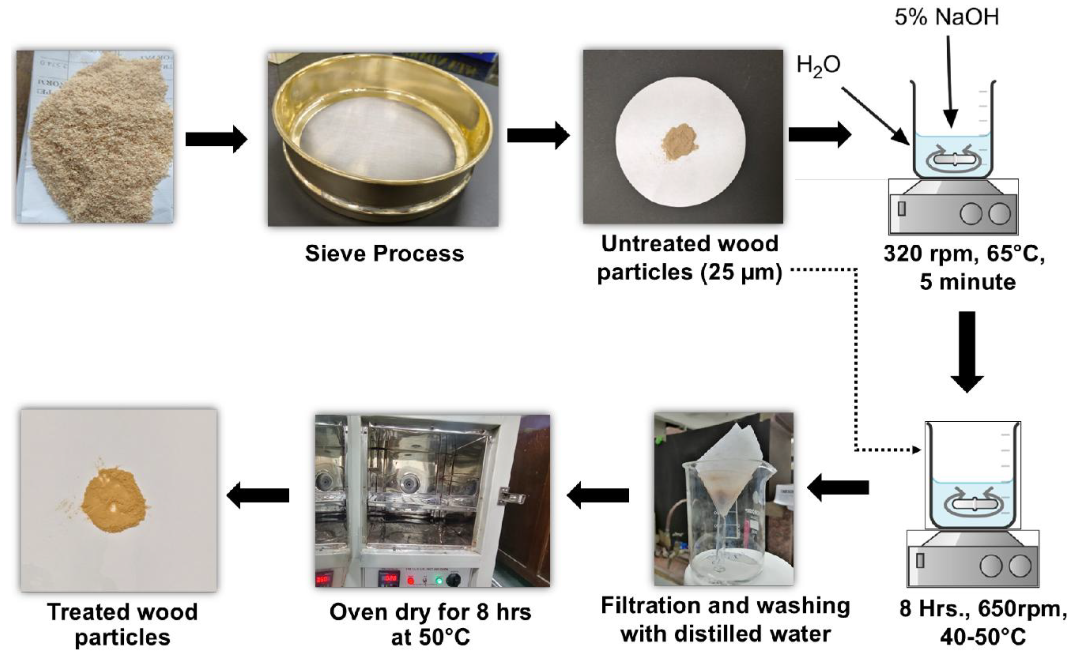
Figure 2.
Development flow diagram of chitosan-wood composite film.
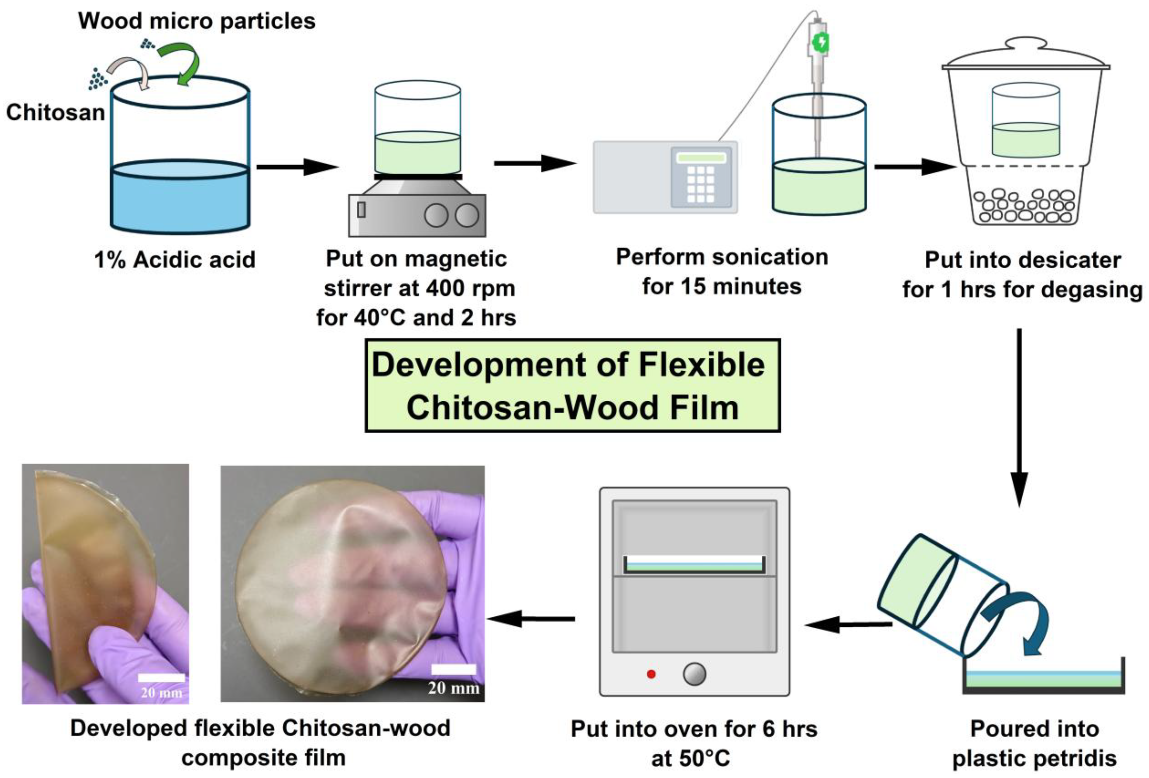
Figure 3.
(a) and (b) DIC experimental setup, (c) developed film with speckle patterns.
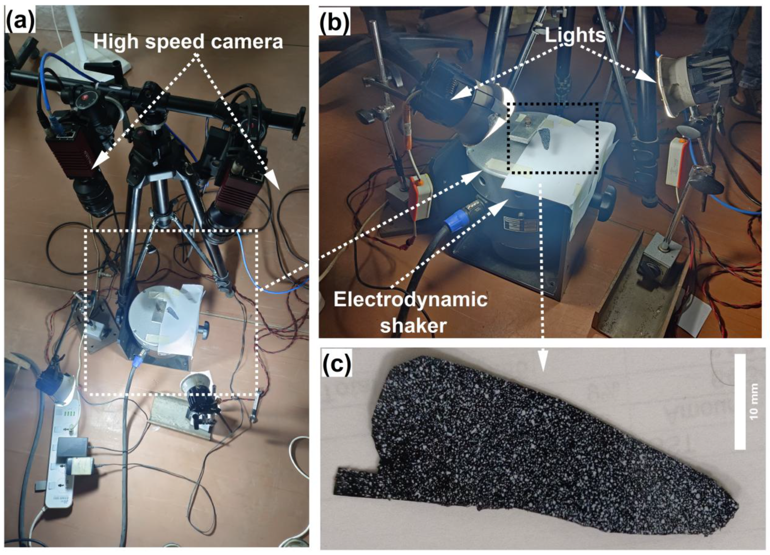
Figure 4.
(a) to (c) Biomimicking of dragon fly wings; (d) to (f) import of CAD model of wings for computational work.
Figure 4.
(a) to (c) Biomimicking of dragon fly wings; (d) to (f) import of CAD model of wings for computational work.
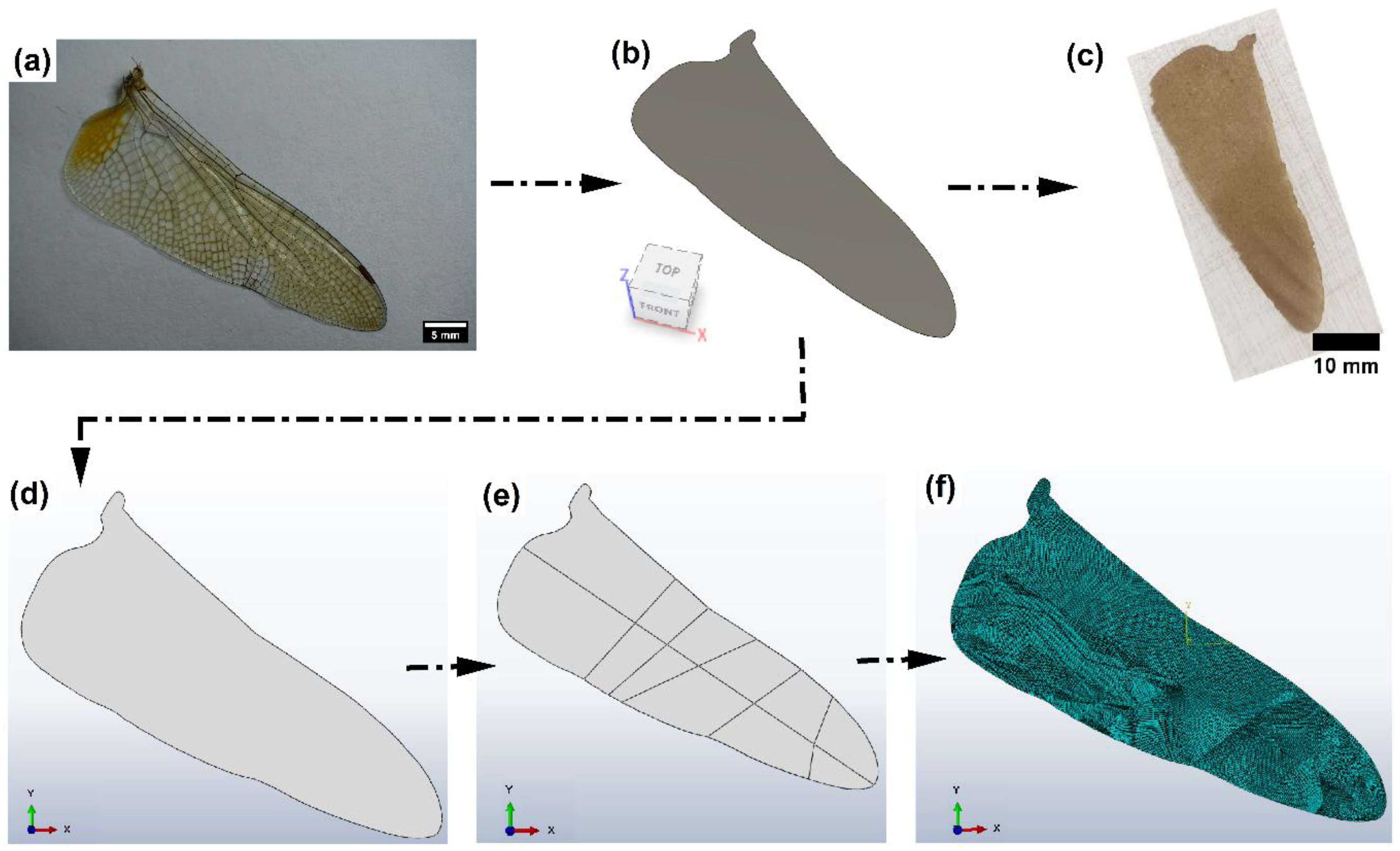
Figure 5.
(a) Morphology of Untreated wood particle, (b) Impurities and smooth surface and (c)Particle distribution of untreated wood particles, (d) Morphology of Treated wood particle, (e)Surface without impurities, rough surface of treated Wood particles, (f) Particle size distribution of treated wood particle.
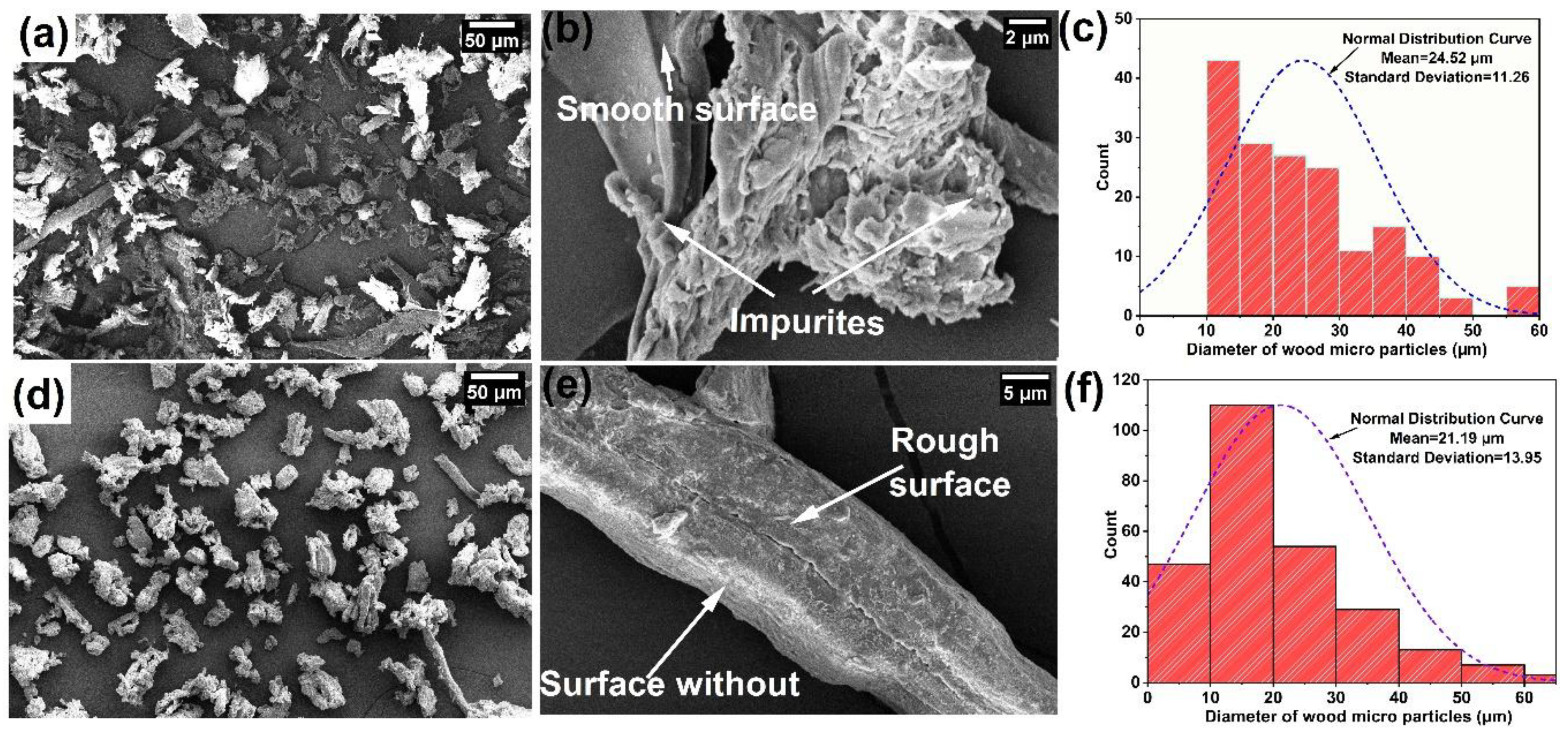
Figure 6.
XRD pattern for treated and untreated wood particles.
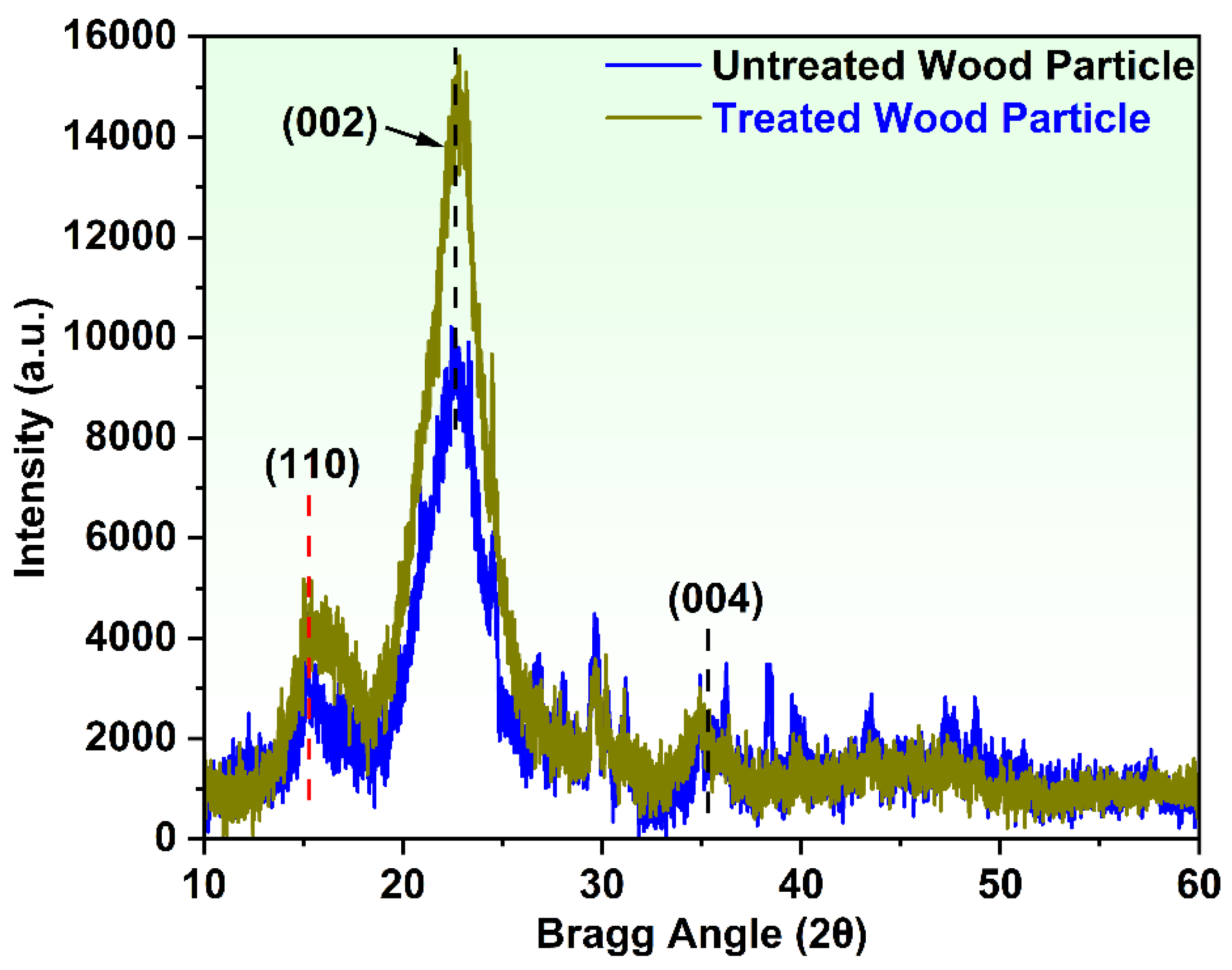
Figure 7.
(a) and (b) Tensile stress-strain curve, (c) and (d) variation of tensile properties for 2% and 2.5% chitosan concentrated different wood reinforced composite.
Figure 7.
(a) and (b) Tensile stress-strain curve, (c) and (d) variation of tensile properties for 2% and 2.5% chitosan concentrated different wood reinforced composite.
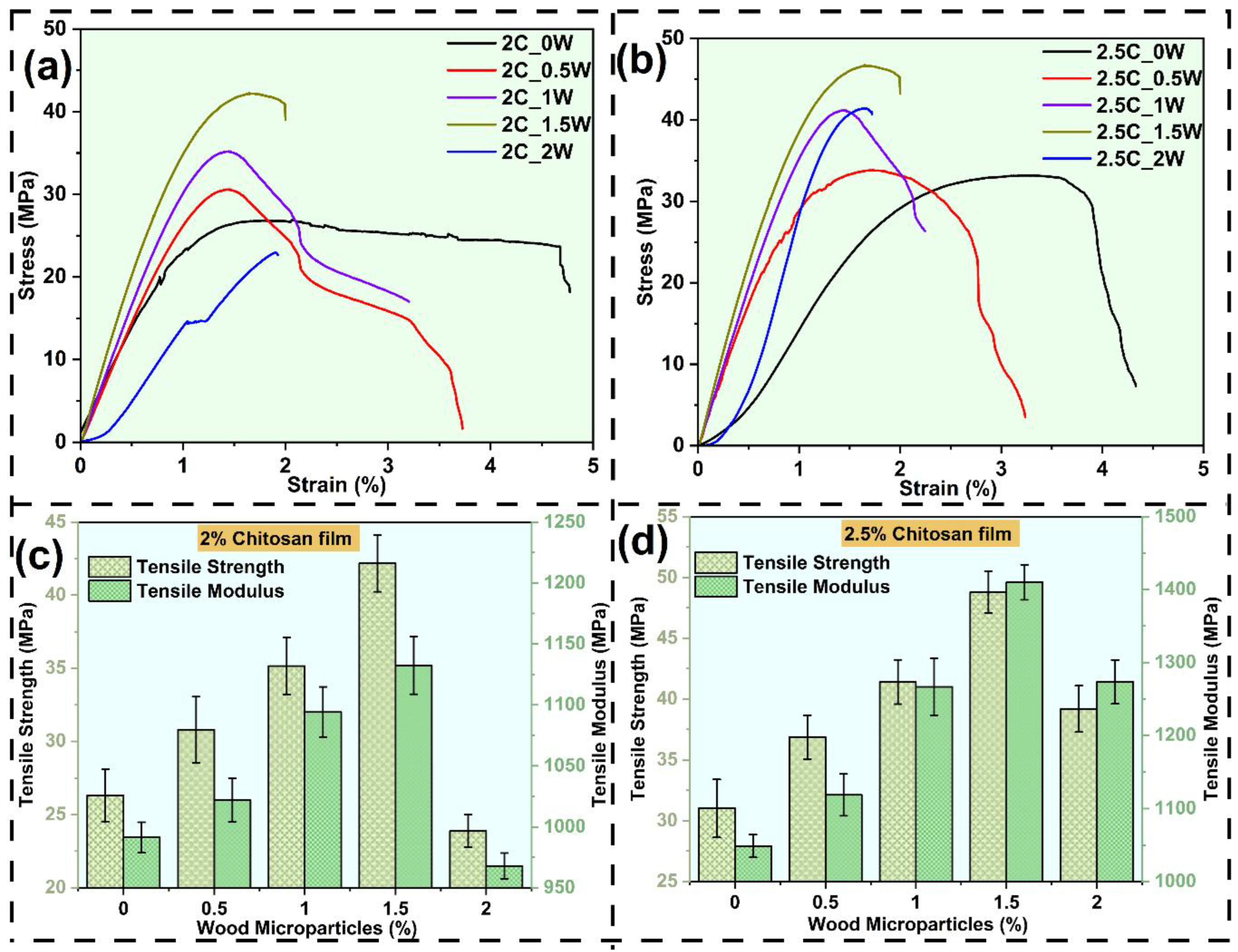
Figure 8.
Storage modulus for (a) 2% and (b) 2.5% chitosan concentrated different wood reinforced composite, damping factor for (c) 2% and (d) 2.5% chitosan concentrated different wood reinforced composite.
Figure 8.
Storage modulus for (a) 2% and (b) 2.5% chitosan concentrated different wood reinforced composite, damping factor for (c) 2% and (d) 2.5% chitosan concentrated different wood reinforced composite.
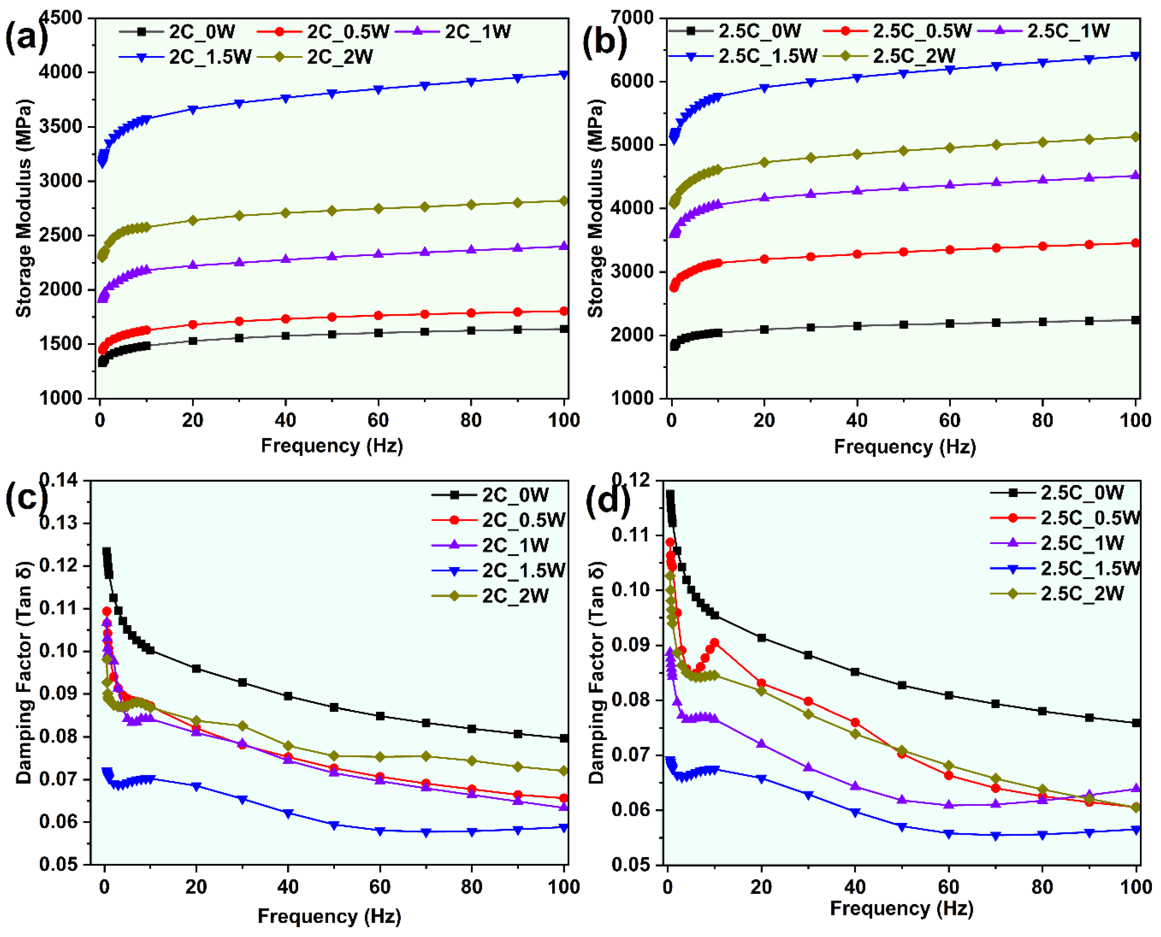
Figure 9.
Natural frequency of developed composite film.
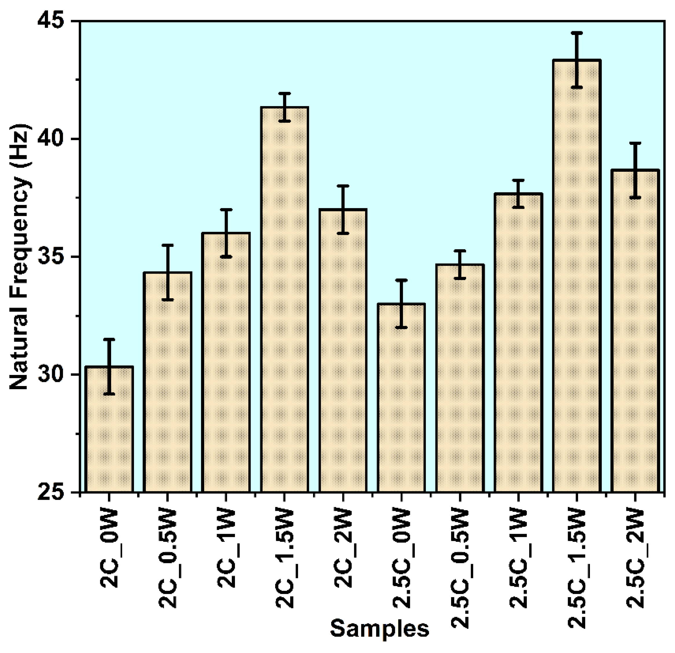
Figure 10.
(a) Mode shape from Abacus, (e) mode shape from DIC experiment.
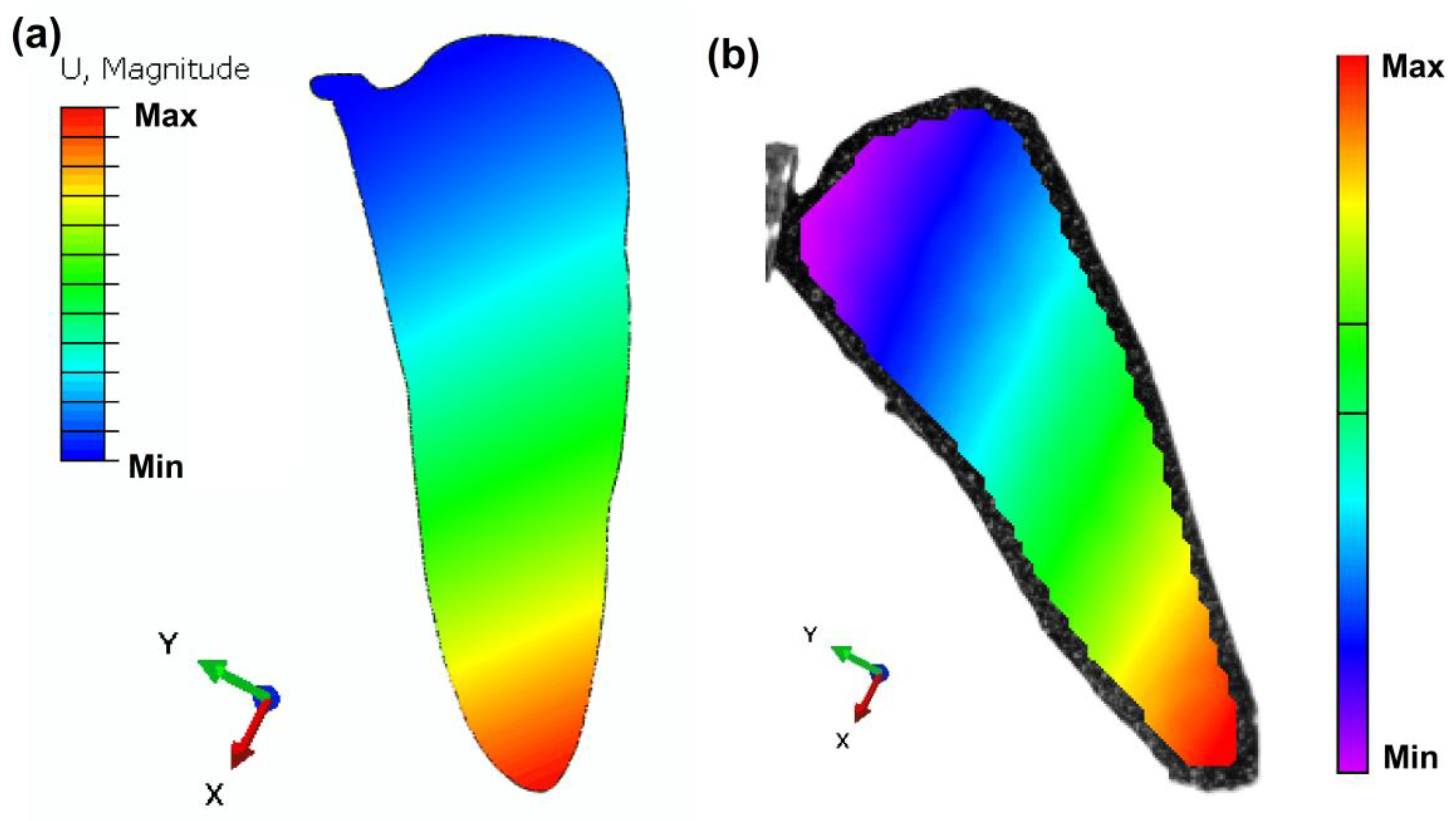
Figure 11.
Contact angle measurements of chitosan (2% and 2.5%) composites.
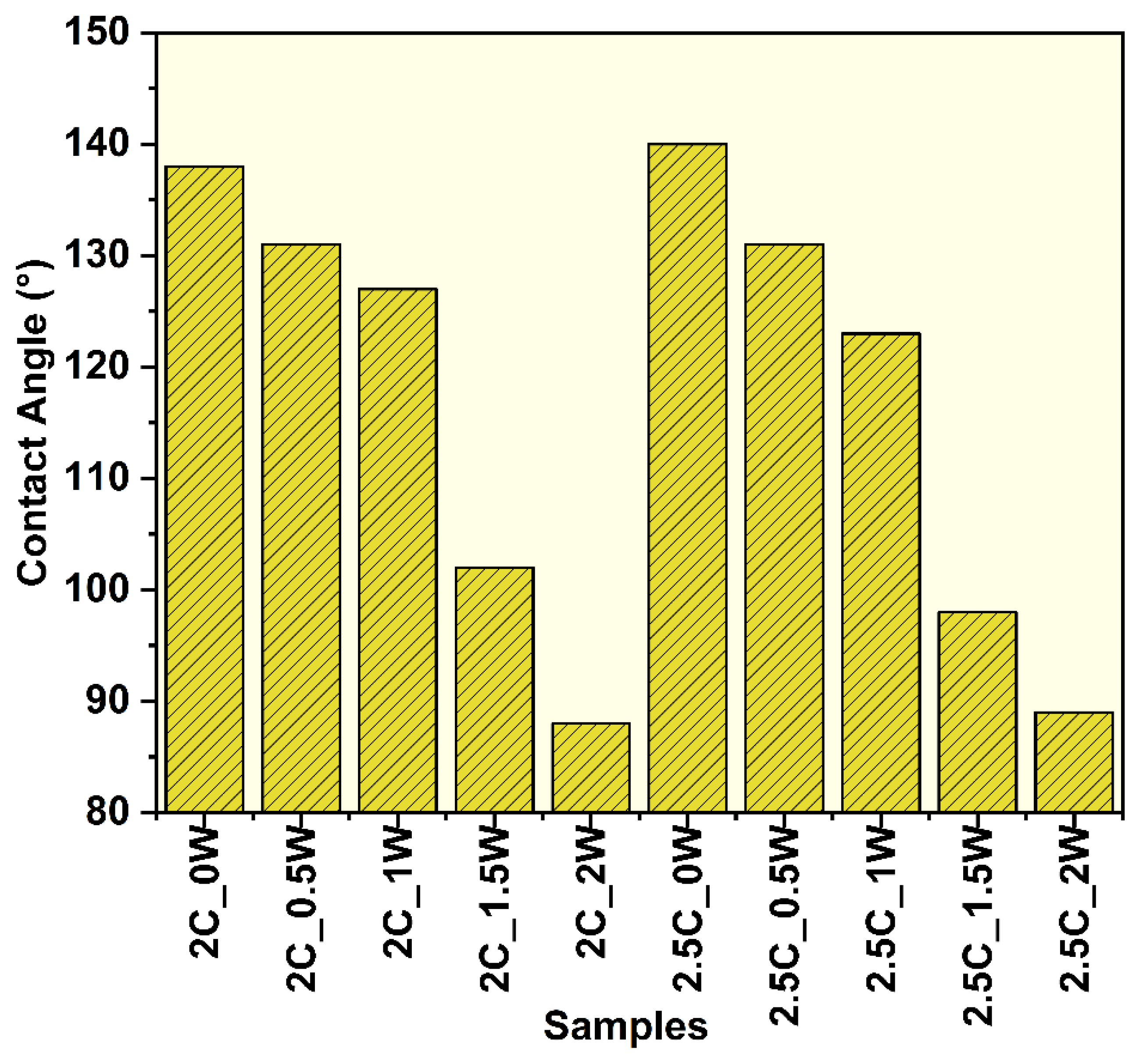
Figure 12.
(a) Thermogram and (b) DTG graph for different chitosan composite film.
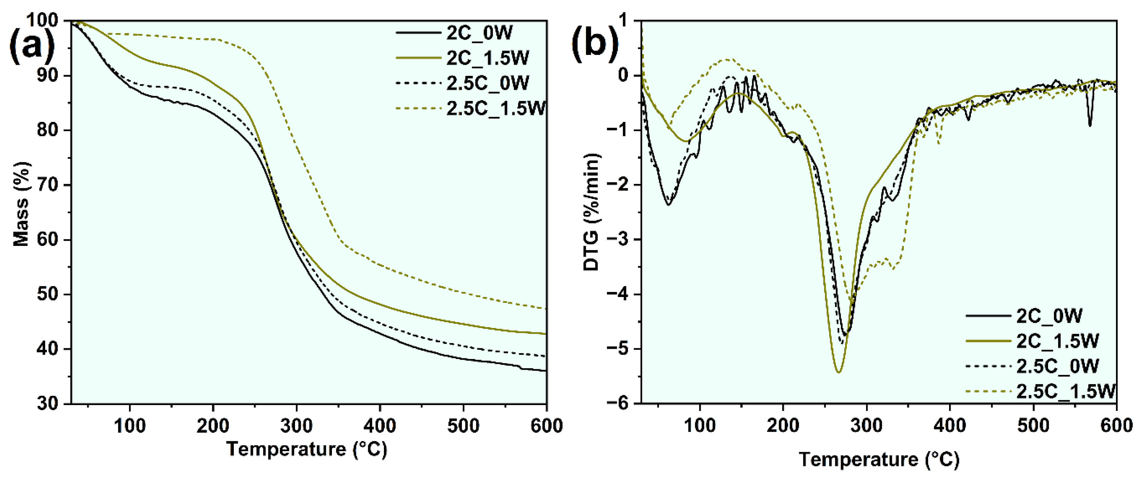
Figure 13.
SEM image of different developed composite film.
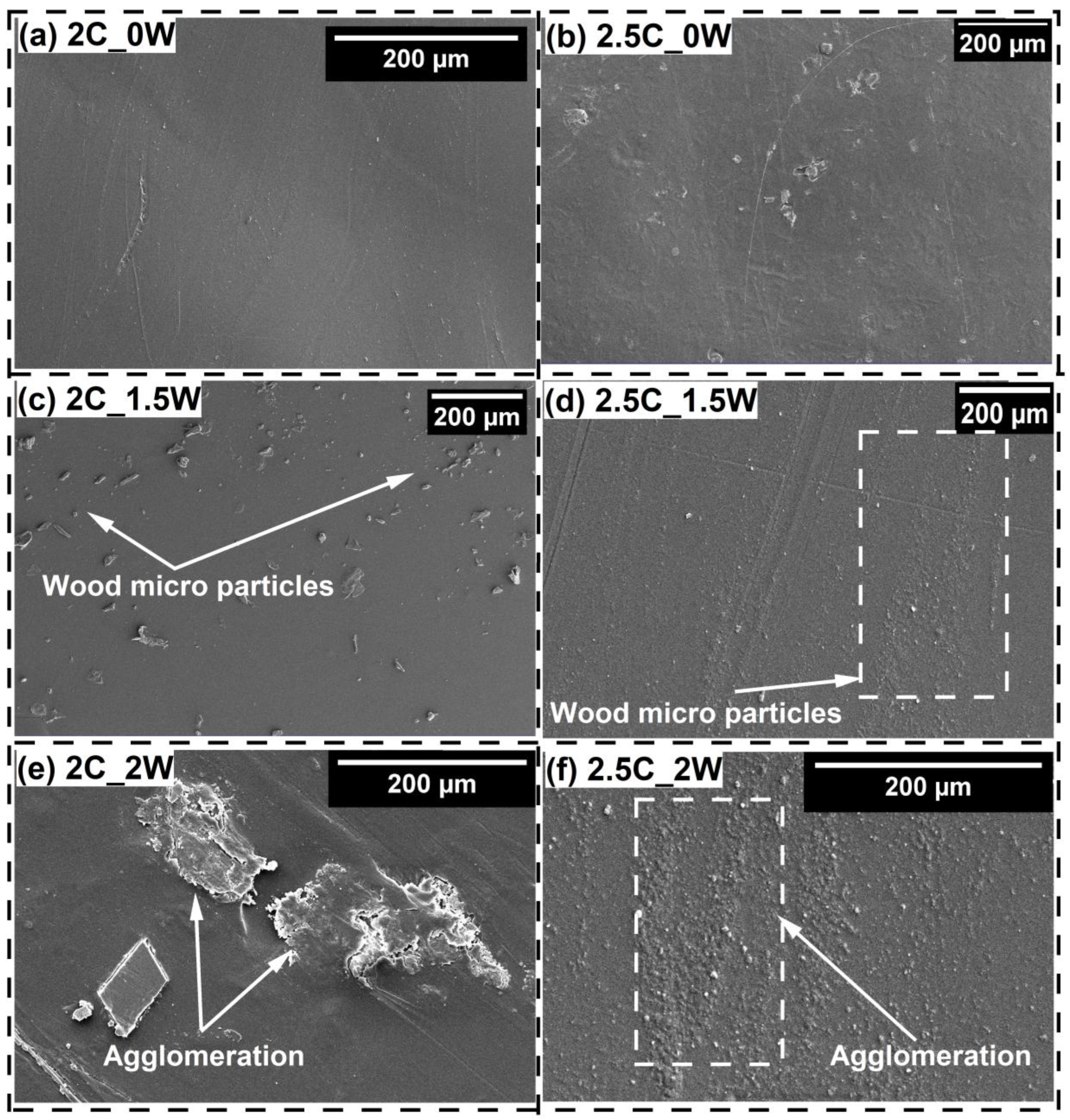

Table 1.
The developed composite sample details.
| Sl. No. | Sample Name | Chitosan (%) (w/v) | Treated Wood Particle (%) (w/v) |
|---|---|---|---|
| 1. | 2C_0W | 2 | 0 |
| 2. | 2C_0.5W | 2 | 0.5 |
| 3. | 2C_1W | 2 | 1.0 |
| 4. | 2C_1.5W | 2 | 1.5 |
| 5. | 2C_2W | 2 | 2.0 |
| 6. | 2.5C_0W | 2.5 | 0 |
| 7. | 2.5C_0.5W | 2.5 | 0.5 |
| 8. | 2.5C_1W | 2.5 | 1.0 |
| 9. | 2.5C_1.5W | 2.5 | 1.5 |
| 10. | 2.5C_2W | 2.5 | 2.0 |
Table 3.
Comparative analysis table of the mechanical analysis of wings with previous literature.
| Sl. No. | Matrix | Reinforcement | Tensile modulus (GPa) | Tensile strength (MPa) | Storage Modulus at 1Hz (GPa) | Damping factor at 1Hz | Natural Frequency (Hz) |
References |
|---|---|---|---|---|---|---|---|---|
| 1. | Chitosan | Wood particle | 1.41 | 48.79 | 3.17 | 0.123 | 40 | Present study (2.5C_1.5W) |
| 2. | PP | Carbon Nanotubes | 1.31 | 24 | 2 | 0.046 | 29.4 | [66] |
| 3. | PP | MWCNT–COOH | 1.2 | 24.5 | 3 | 0.1 | 23.19 | [18] |
| 4. | Chitosan | Nanocrystalline cellulose | 1.5 | 57.2 | -- | -- | -- | [67] |
| 5. | Natural wing | 1.5 | -- | -- | -- | -- | [68] | |
| 6. | Natural wing | 3.75 | -- | -- | -- | -- | [69] | |
| 7. | Natural wing | 2.74 | -- | -- | -- | -- | [70] |
Table 2.
Mass loss details of the developed composite film.
| Sample name | Stage-I mass loss (%) | Stage-II mass loss (%) | Stage-III mass loss (%) | MRDT (°C) | Residual Mass (%) |
|---|---|---|---|---|---|
| 2C_0W | 13.5 | 44.0 | 25.7 | 268.1 | 35.9 |
| 2C_1.5W | 7.7 | 42.5 | 19.4 | 269.4 | 42.7 |
| 2.5C_0W | 11.8 | 42.8 | 23.4 | 270.6 | 38.5 |
| 2.5C_1.5W | 2.6 | 34.8 | 25.6 | 283.7 | 47.1 |
Disclaimer/Publisher’s Note: The statements, opinions and data contained in all publications are solely those of the individual author(s) and contributor(s) and not of MDPI and/or the editor(s). MDPI and/or the editor(s) disclaim responsibility for any injury to people or property resulting from any ideas, methods, instructions or products referred to in the content. |
© 2025 by the authors. Licensee MDPI, Basel, Switzerland. This article is an open access article distributed under the terms and conditions of the Creative Commons Attribution (CC BY) license (http://creativecommons.org/licenses/by/4.0/).
Copyright: This open access article is published under a Creative Commons CC BY 4.0 license, which permit the free download, distribution, and reuse, provided that the author and preprint are cited in any reuse.


