
Submitted:
06 June 2025
Posted:
11 June 2025
You are already at the latest version
Abstract
The modern coinage industry ensures for its products dimensional and weight precision and also an improved surface quality. The speed of coin mass production requires increased performance for the used machines and tools. Despite of these, the errors incidence cannot be excluded. Some of these errors are recorded inside the punching machine, and generates the clipped blank disks; on their turn those malformed discs led to the clipped coins. In the first part, the paper presents the premises insight the clipped blanks apparition. There are exemplified some coins having different types of clips: curved, straight and ragged. The literature review in the coinage field covers the subjects as coin and dies behavior under the striking load, viewpoints on 3D modeling and FEM analysis, respectively insights on various striking errors, most of them more or less valuable as collection metal pieces. The paper main purpose is outlined: to study, using the available modern techniques, the particularities of different clipped coin types. In the paper second part, is introduced the adequate 3D model, for such parts as the dies, collar, respectively the coin. It follows the assembled model corresponding to each studied case, which consist by the obverse and reverse striking dies and the collar, having inside them the coin. For each of the models, based on initial conditions, the finite element analysis is realized. The paper last part presents the analysis results, the discussions and conclusions.
Keywords:
metal coin
; coin error
; clipped coin
; metal sustainable recycling
; 3D modeling
; FEM analysis
; collectible item
1. Introduction
From the Antiquity, the coins were simply made by hand, using the hammer to strike each blank metal piece between the previously engraved two dies [1]. The resulted coins by this technique were often called hammered coins [2]. Despite of the exquisite craftsmanship of the figures representation on coins, hammering was an imprecise striking procedure; in many cases, the used force wasn’t always correctly applied [1].
In modern times, after many attempts to improve the coinage techniques, the mill and screw press was introduced in Europe: the pressing force was increased by the vertical screw rotation. As a result, the quality and quantity of manufactured coins was improved. Since then, the coins made using some machinery were called milled coins [2]. As a consequence of industrialization the steam-power machines were used at the end of 18th century, in order to obtain higher pressures and an improved surface quality.
In our days, the used manufacturing machines allow the simultaneously striking rate consisting in few hundreds coins per minute [2,3].
The public confidence in a sustainable currency was always crucial; along time, one of most significant problems was to maintain the uniform metal composition, dimension and weight for all released coins having a given value, especially those made in precious metals as silver or gold [4,5,6,7]. For hammered coins in precious metal, the uniform weight was obtained by weighting respectively filing or clipping the exceeded quantity of material, procedure which usually changed the coin shape [6]; the accuracy of this procedure was influenced by the weighting precision and also by the used technique. As example, in Figure 1 is presented a Dutch large silver coin, leeuwendaalder, from year 1648, which circulated for decades in Europe and North America and gave its name to local currencies adopted later in some countries [8,9].
The lack of uniformity was followed by various “adjustments” made by everyone interested to gain few grains of valuable metal on each coin, by clipping the edges by adequate tools. To prevent these, the authorities introduced various penalties; also, different standard weights patterns were made and used to check the coin weight [9,10].
Following the modern improvements in coining industry, as collar ring for the coin edge, the dimensional precision increased, also the coin weight was maintained in the legal prescribed limits. To prevent private clipping or counterfeit coins, the serrated or text engraved edge was introduced as security feature [2].
2. Clipping Errors in Blank Discs Manufacturing
To obtain the desired coin, a preliminary half-finished piece is needed to be strike; there are used blank metal discs, punched from a metal stripe on adequate machines [11,12,13].
For a sustainable procedure, in order to avoid the metal waste, on a given metal stripe, the number of discs that are needed to be punched is related with the maximum proportion of used material; the discs can be arranged on the stripe at least on single row, but is also possible the simultaneously punching on multiple rows [12,13,14]. In Figure 2 is presented the disc arrangement on three rows, but the literature indicate, in some cases, a maximum number reaching from 7 to 11 rows [12,13,14]. After obtaining the blank discs, the perforated metal stripe needs to be eliminated from the punching machine and recycled, so a minimum rigidity is still required for a secure handling [12,13,14,15]. To ensure this condition, after perforation procedure some little connection bridges must be obtained: between the neighboring disc holes and, also, between the disc hole and the stripe margins. The dimensions represented in Figure 2 are as follow:
- D – diameter of the perforated hole, respectively for the resulted blank disk;
- a – distance between the hole center and stripe edge;
- b – width of remained bridge between two neighboring holes;
- b’ - width of remained bridge near the stripe margin;
- c – center distance between row holes along metal stripe;
- α - angle between the center line defined by two consecutive holes on the same row and, respectively, the center line defined by two neighboring holes belonging on different rows;
- B and L – the width and length of the metal stripe;
- s – the thickness of the metal stripe, respectively blank disk.
The bridges dimension depends mainly by the stripe thickness and disc diameter; there are also considered the metal properties and the stripe advancing and indexing mechanism inside the punching machine. Some authors [13,14] recommend different values for neighboring discs holes bridges, b, respectively for margin stripe bridges, b’. There are other authors who recommend the same dimension for both types of bridges, b=b’ [12]. During the blank disc perforation some failures could appear; then, the bridges size is changed, so the holes arrangement on metal stripe is perturbed and properly blank disc may result incomplete.
If the stripe advancing step inside the punching machine changes during perforation, the result is the overlap of the current perforated disc and the hole leaved by precedent one. From Figure 3 can be observed the influence of the changed advancing step, decreased with dimension x: the holes center distance along the same row decrease and the angle α increase to α'. For the misalignment value x>b, the bridge portion between holes disappear and the result is the incomplete disc, named in literature curved clipped blank [16,17]; from the Figure 3 result that the clipped portion have the same size for all damaged discs. If the misalignment x is increased, the center distance between the holes on neighboring rows decrease lower than D and the blank discs may result having multiple clipped portions.
If the stripe guiding system inside machine is perturbed, the misalignments are followed by disc perforation outside the stripe, as is presented in Figure 4. For the metal stripe angular misalignment β (rotation relative to the stripe corner) the resulted incomplete discs are named straight clipped blank [17,18]. Since the stripe misalignment varies on the lateral edges from the dimension ymin to ymax, the discs begin to be clipped from y=b’ to ymax; their clipped part dimension is not constant.
If the perforation begins or ends outside of the stripe ends and the misalignment value is x>b’, the result is the straight clipped blank, as presented in Figure 5; on the subjected discs, the clipped portion has the same size.
During perforation, the resulted discs and holes edges will undertake the marks of tools clearness; at a close look, along the thickness, the resulted surface will present the cut and tears portion [16], as presented in Figure 6, f. For the blank discs, this edge surface condition is changed during the next operation, when the rim is obtained by decreasing the disc diameter and increasing the thickness on the margin; the edge quality is also improved. On defective clipped portions, the edge condition will remain unchanged. The curved clipped edge keeps the previous perforation traces and the straight clipped edge takes the previous edge condition from main metal stripe. If the surface belonging to the stripe edge is not well finished, the clipped edge on the disk will result with that irregular shape as ragged clipped blank; in the literature, the incidence of ragged clips is related mostly with the stripe ends [17,18]. The simultaneously appearance of combined misalignments should not be excluded; this led to blank discs having various clippings type [17,18].
Usually, the clipped blank disks should not pass the checking control for the next operation; in a sustainable approach, there must be considered scrap and redirected to the recycling procedures. If the clipped blank is not detected, it follows the next operation, together with other complete discs. Due to the clipped blank disk imperfections, such operation as edge rimming or edge inscription punching could be inconsistent or fail; the tools damages should not be excluded [3]. Finally, if a clipped blank pass by the coin striking step, will result the coin with the clipped blank error.
Beside the changed shape, the clipped coin weight is decreased; this could cause inconvenient in using this defective manufactured piece on the market, especially if the content is precious metal. Another undesired inconvenient is the rejecting from mechanical devices, as vending or counting machines, which have fine adjustments related to regular coin dimension and weight. These inconvenient may induce the fear to use the currency and the lack of trust [6,19].
Despite the inconvenient, as collecting item the clipped coins are included by catalogues in the error coins category, desired and highly appreciated by collectors. The adequate literature records various round or straight type clipped coins, valued following some criteria as clipping size and type or eventually coin condition; the coin having a spectacular clipped error requires a higher price [19,20]. To measure the size of clipped portion, in the literature is counted the percentage of missing material by weighting the damaged coin, then related to the nominal weight; the dimensional measurement are not excluded. The Official Red Book of the United States coins [9] defines as coin with clipped planchet error; those have a missing part from 10 to 25% of the metal content. For a correct indication of the clip size in catalogue, some authors introduced a measurement increment size to each 5%; the clips without a particular mention of percentage are considered to have less than 5%. Other authors consider indicating also the percentages below 5% or those within the round values [16]. Finally, there are authors which doesn’t give a percentage of the clipped portion and leave the eventually estimation to be made based on the given photographs [20,21,22]. Since the clip incidence on coin edge is random, its position is indicated by most authors related to engraved figures on coin obverse; in analogy with the clock dial [16]. For example, “a 5% curved clip on 12:00” or “a 10% straight clip at 6:30” are two examples indicating the clip position on coin obverse.
As examples, in Figure 6, Figure 7 and Figure 8 are presented some modern coins manufactured on different types of clipped blank. The image scale for all coins was slightly reduced; for clipped detail, the scale was adequately increased.
Apparently, the clipped blank error consists in a simple cut from the entire piece, so the temptation to privately produce its correspondent forgeries is not excluded. Based on their experience, some authors [16,18] are providing useful guidelines to the interested collectors to help the checking of the suspicious pieces. There are counted some clipped coins characteristics, as the strike and rim weakness, the radial metal flow in the subjected area or the clipped edge condition. But those characteristics must be related to the specific manufacturing conditions which reveal what caused the particularities of the clipped coins.
3. Coinage Manufacturing Field Researches
In the last years, the literature related to the coinage industry reveals new achievements, by studying different aspects of coins manufacturing, as the coin material behavior under load, the surface quality or the tools durability along the coinage process. The most important and comprehensive contributions in the coining field are mentioned as follow.
The first application of the finite element method in the study of coin minting is the work of Brekelmans et al. [23], focused on the estimating of coin material flow and the needed coining pressure in order to obtain a conical relief figure pressed in the centre of a sample piece. As result, accurate information on the corresponding stresses and strains were obtained. The upper bound theorem applied upon a quasi-static formulation with elasto-plastic constitutive equations, was used in the article. The applied methods were detailed and evaluated, so a quantitative comparison within experiments was used to validation. An excellent agreement was found. The work findings were highly appreciated by subsequent authors in the field.
Cotton et al. [11] paperwork improved the coining forces depending by different coining shapes. A simplified force calculation formula was introduced: the strengthen coefficient, the strain hardening exponent and the metal sheet thickness, before and after coining, are considered. The friction between the metal sheet and tool is also considered. Then, the experimental coining in dry condition of two metal sheets was purchased by ring compression test. To perform the numerical simulation, the adequate software Forge NXT2 was used. The comparisons between the measured and estimated forces revealed the better results in coining forces estimation using the proposed formula.
A comprehensive review of literature of the forging tools durability for hot closed die forging is realized by Ficak et al. [24]. According to the classification of wear on forging tools, abrasive wear, plastic deformation and fatigue cracking are predominant, and were estimated by authors by 85%. Some methods to improve the tools lifetime were studied by authors. A durability comparison between different steel designation punches and the heat treatment effect on tools failure was also revealed. A ring compression test for different lubricants was presented to compare the obtained friction coefficient on mechanical and hydraulic press. The aspects on tools reconditioning and their life prediction are also revealed. The research accuracy and the paper findings are useful in coining tools manufacturing.
Keran et al. [25] article improves the accuracy of force prediction model for the case of closed die coin striking process. The coin striking is considered a micro-forming process, so the microstructure of the work piece material and coined geometry reduced dimension have a substantial influence on the of material deformation phenomenon. There are studied three samples having three different crystalline grain sizes. To obtain the accuracy of introduced force prediction model, the experimental and modeled data were statistically analyzed and graphically presented by authors.
Pragana et al. [26] in their work introduced a new hybrid manufacture process in order to obtain collector coins having holes with complex contour in their design. By combining metal deposition with metal cutting and forming, the production of these coins with intricate inner contour is experimented. First, the primary cylinder was obtained from steel powder deposition, having the inner hole with desired complex contour; then, the blanks were sliced and polished. After determining the blank material relative density and the flow curve, the coin minting testes were purchased, using a special designed press tool placed on a hydraulic press. The dies, having the central recess of relief at 0.15mm and the collar, were used on two types of tests, obtained following the stroke preset: the incomplete minting, respectively the complete minting. The numerical model of the minting process was performed using finite element i-form program. The deposited blanks were considered as continuum medium with an average relative density. After the model analysis, it was observed that the contact between the blank and dies start with the outer ring and continues with lettering. Then, the impression of relief and inscriptions led to a non-symmetric pressure distribution during minting, which may have effect on the pressing tools, by creating a bending moment. Using the experimental results and the finite elements, were predicted the evolutions of the force with die stroke during coin minting on the additively manufactured blanks, made from stainless steel. The conclusions highlighted the advantage of using the hybrid manufacturing application in collector coins production.
In their work, Alexandrino et al. [27] introduced a new finite element method designing procedure in order to realize the needed corrections on the coining die figures and to optimize the applied pressure distribution. By this approach, a new alignment of the resultant force on vertical direction was realized at the end of the die stroke. The introduced innovative design solution is to adjust the position of the engraved die model by tilting the obverse and also the reverse die reliefs. The numerical simulation was able to be used in the die model shapes optimization and to reduce coin striking forces and also to extend the die life. Using the finite element it was presented the predicted evolution of the force vs. die stroke. The author’s innovation was successfully applied at state mint of Portugal: two collection coins, commemorating the Portuguese ethnography, respectively the age of iron and glass in Europe, were minted in 2017 [28].
Zhong et al. [29] studied the apparition of flash line defect in coining process. According to the authors, flash line failure is an important surface inconvenient appeared on the manufactured silver commemorative coins. Due to the lack of study on the producing causes, the failure requires a long procedure to be eliminated, an increased number of die tryouts and development costs. In this paperwork, the producing mechanism of flash line is carefully studied by authors through the coin metal flow analysis, using the modern finite element method. The research revealed the main reasons of the flash line defect: the radial components of friction between the die and the coin blank during the striking. Also, the work reveals that the defects easily appear in the model field plane areas where the metal flow presents compression and horizontal extrusion; the dies heat treatment and recorded stress were also important in the subjected areas.
The flash line defect in commemorative coins manufacture process was also studied by Xu et al. [30]. During the research, is considered that the elasto-plastic behavior of porous materials led to deformations, where the constitutive minimization level updates are the result of a local variation problem. For different strokes, it was studied the material flow, during the entire coining procedure. The change in the flow direction of the material in the coin outer rim region is responsible for the flash lines appearance. Also, the distribution of the flash line on surface is obtained by increasing the friction on radial direction related to the work model. The authors proposed new rim geometry of the coin blank, to avoid the flash-line defects; the proposed improvements led to good agreement with the realized experiments.
Adequate predictions related to the stress distribution and material flow in coining manufacturing process are revealed in Peng et al. work [31]. To study the stress distribution and material flow in coining processes of a bimetallic commemorative coin, the authors used a professional software, Deform 3D. The researches revealed that the stress concentrations appear at the corners of striking dies and the material interface in case of bimetallic coin. Because two materials having different characteristics are adopted for the coin core and also the ring, the obtained numerical results indicate where the increased stress values occur: at the coin edge and at the interface between two metals – if the bimetallic coin has the soft core. Also there, a deep adhesion occurs at the interface of the metals; the authors reveal that, the use of hard material for the inner core and the soft one for the outer ring may cause inadequate coin parts assembly and falling of the coin core.
To improve the analysis of the material flow during the coining process, Xu et al. [32] developed in their work new commercial software called CoinForm. The proposed software facilitates prediction of the applied embossing force and also the geometry optimization for the working dies.
In the article of Tavodova et al. [3], there are studied the premises of dies production process, in order to increase their lifetime. On the manufactured die samples, were investigated the conditions of dies failure apparition in the case of intensive use. After a comprehensive research on samples microstructure, the identified failures were the surface wear and also the die material cracks. On a proposed sample, the heat treatment was improved in order to eliminate the internal stress and the produced coin number was increased. The authors recommend the use of high purity steel and improvements on dies manufacturing process, as the heat treatment method and chrome plating by new coating methods.
Torsakul et al. [33] are focused in their work on tools life improvement used in the coining industry. Based on the die cracks defects incidence on some recent Thailand coins, the authors developed their research in order to improve the dies lifetime and to prevent their surface damages. There are compared the characteristics of three types of materials to be used: alloy steel, cold working tool steel and hot working tool steel. The each dies sample was heat treated and coated with CrN or TiN and then used to stamp blank discs; after manufacturing a number of stamped discs the dies coated surfaces were studied. To investigate the adherence of applied coating layer, the scratch test was performed and the coating types were compared. The appeared cracks during tests were also investigated to obtain useful data for some further improvements. The research results were successfully applied at Royal Thai Mint in manufacturing current baht circulating coins.
As studied coinage literature reveals, modern methods as 3D modeling and FEM analysis are used to improve the theoretical support for the striking condition, to resolve different issues appeared on the coin striking, to improve the tools durability, or, respectively, to study the appearance of some coins manufacturing errors. There are counted remarkable achievements but, the studied literature is poor into the direction of approaching by mentioned modern methods the striking particularities for some interesting valuable clipped coins, as collectible items from the past times. The necessity to study the particularities of the clipped coin error is highlighted, in order to ease the valuation expertise on certain former error coins, viewed as collecting item. On the other hand, the clipped coins having an adequate estimated catalogue value are increasing the collector satisfaction as customer and, also, are able to promote the sustainable consumption practices in the coin collecting field [19,34].
3. Computing the Virtual Model
The coin chosen to be modeled is a nickel plated steel 10 lei from 1992, having 60 millions issued pieces [35], from which are recorded the both types of clips, as previously presented. The coin diameter is 23 millimeters and the thickness 1.8 millimeters [36]. The virtual model will contain, as constitutive parts, the striking negative dies, the collar and also the coin in three variants: without clip, with curved clip and, respectively with straight clip, as presented in Figure 9; due to the similarity with the straight clip and also the complexity of the edge surface, the ragged clip is not modeled. For both modeled clipped blanks, the clip portion was placed in the same position, related to the figures represented on coin. Its interference was established for both clip types to 1.15 millimeters from coin edge, means 5% from coin diameter. On both faces, the engraved figures have 0.15 millimeters deepness from the flat field [26]. Some unnecessary fine details of the engraved figures represented on the obverse and reverse were simplified [37,38]. In the ensemble arrangement, it was counted the coin angle between obverse-reverse figures, 00: while the obverse figure is placed in normal position, the reverse figure is placed also in normal position [37]. The virtual model was computed using the facilities offered by CATIA software, module Part Design [39,40].
After their individual computing, the obtained parts were combined to obtain the ensemble models: between the same dies and collar, the three different coins were introduced. Using the CATIA software’s Assembly Design module [39,40], the assemblies are computed, as is presented in Figure 10.
For the analysis, there is considered the advanced stage of striking, in which there is no change of diameter and the metal fill all the embossed relief [26,27]. Counting the striking particularities and the corresponding contact between the figures represented on dies, respectively the coin faces, the ensemble adequate constraints are defined. The contact areas, defined between the striking dies and coin, covers the entire common area for each engraved figure; it was also considered the presumption in which the flat field is plan and there are no misalignments inside of the pressing machine [12,37]. Between the collar and coin circumference, respectively the collar and dies the contact was considered along their common diameter.
4. Finite Element Model, Analysis and Simulation
In order to perform the analysis, the ANSYS software is used [40]. The analysis objective is to determine the coin behavior under the applied load, on each of the considered cases. A special attention is given for the both types of coin clipped portion. The obtained finite element model view and geometry, computed for all three studied cases are presented in Figure 11.
The chosen material for cancelling dies and collar is hardened steel; for the coin material is mild steel [38,41,42], with the mechanical properties as presented in Table 1. In the studied coin clipped area, respectively in the contact area, a smooth mesh with the minimum edge length equal with 0.001 mm was chosen. The finite elements size varies between 0.15 mm and 1.2 mm; the smallest values are in the coin clipped area and also in the contact region between the assembled parts. There were used the tetrahedral-type finite elements; their shape is the best 3D-type finite element, which provides the smallest discretization error [41,43]. The established values for the finite elements size were chosen in accordance with the dimensions of the engraved figures represented on surfaces. In the each studied finite element model, a bonded contact type was engaged in order to reflect practical conditions. The decision was taken because the construction assembly does not permit horizontal motion of the coins or dies.
5. Results and Discussion
The results obtained for all three studied cases are presented in Table 2 and also, in Figures 12 to 19. Each data set consists in total deformation and the maximum equivalent stress on the studied coin material. The values detailed in Table 2 should be viewed as relative and useful to evaluate the different studied cases.
For the first studied model, containing the unclipped coin, the total deformation is presented in Figure 12. Due to the collar, the pressed coin metal deformation is decreased around the circumference. Counting the different areas of the recessed relief represented on dies, their rigidity is different and the metal flow tendency thru the coin edge is more pronounced on reverse; the maximum values are distributed on a larger area than on obverse.
The equivalent stress distribution is relative uniform on most coin surface, as represented in Figure 13. The minimum value is placed on the coin central surface, which corresponds to the flag representation on obverse, the largest area that needs to be filled with the coin metal on striking operation. The maximum value is recorded on the intersection between the coin flat field and raised edge rim. The results agree also with findings from [26,27].
The second model contains the curved clipped coin. The clipped portion leaves between coin blank, collar and dies an empty space that need to be filled with the neighboring coin metal. Because the lack of a closed space, the coin metal allowable stress limit may change, decreasing until 30 - 50% [13,14,44]. The total deformation represented in Figure 14 record the metal flow toward the free space, so the clip edge is deformed thru outside. Due to the different areas of the engraved relief represented on dies (detailed in following Table 3), their rigidity is different and the flow tendency is more pronounced on reverse.
As can be observed from Figure 15, related with the unclipped coin, the equivalent stress values are slowly decreased for the curved clip coin. The decreases are significant in the coin center and on the clip edge. Due to the coin metal flow, the maximum values are recorded where the clip intersect both the rim and flat field, which correspond to an increased metal deformation in that area. The results agree with the real details of a curved clipped coin from Figure 16.
For the third model, which contains the straight clipped coin, the results are presented in Figure 17 and Figure 18. Than in previous case, the metal tendency is to flow into the empty space, as it can be observed at real straight clipped coin details from Figure 19. Due to the straight clip geometry, the remained coin edge area is decreased more than to the curved clip (as presented in Table 3), so the free space is larger. Compared with curved clip, the amplitude of this phenomenon is slightly increased and the straight clip edge is more deformed thru outside. This explains the observations from literature [16]. The equivalent stress representation from Figure 18 reveals the similarities with curved clip case; the maximum values, slightly decreased, are recorded also on the clip intersection with both the rim and flat field, where the metal deformation is increased; this agrees with representation from Figure 19.
In the particular situation when the clip size on blank disk is reduced and the metal deformation during striking reach the collar, the coin round shape is restored and the clip type cannot be distinguished. In the corresponding area, only the rim and its neighboring figures remain not raised after striking, indicating the clip incidence. Such details of small clipped coins are presented in Figure 20. Like previous figures, the image scale for all coins slightly reduced; for clipped detail, the scale was adequately increased.
To easy the comparison between the previous results, in Table 3 are given the areas for different contact portions belonging to each studied model, on coin obverse and reverse; their values were measured using the software facilities.
6. Conclusions
In the present paper, the manufacturing particularities of different clipped blank disks and their striking procedures are studied. The performed research led to the following conclusions:
- -
- In order to avoid the metal waste, a sustainable manufacture requires the maximum proportion of used material after the half finished discs perforation from the stripe. Due to this optimization combined with perforated stripe rigidity, the discs arrangement on stripe leaves some bridges between them;
- -
- During the blank disk perforation, some errors may occur related to the metal stripe advancing and guidance mechanism; this may lead to the clipped disks apparition. The size of clipped portion has its influence in decreasing the contact areas between the clipped coin and dies, respectively clipped coin and collar;
- -
- In the case reduced clip size, there are influenced the contact areas on the coin edge and on the raised rim area. Increasing the clip size, the flat field contact area is also affected. For a more increased clip, the different represented raised figures on coin faces are passed by the clipped portion; their contact area decreases;
- -
- Since for regular coin, if the striking continues over this limit, then the force and deformation exceed, for the clipped coin case, the missing portion changes the condition of fully constrained material inside a closed space: after the stroke completing, the metal is dislocated only thru the clipped empty space;
- -
- In the studied cases, the rim is wearing the traces of the metal dislocation. On the clipped edges, there are recorded the equivalent stress maximum values and also the maximum deformation. The metal tendency to fill the empty space lead to a deformed shape of the clipped edge and to a defective impression of the coin figures in the clipped area, as also observed by other authors;
- -
- Due to reduced contact areas, the equivalent stress maximum values and also the total deformation are increased for the clipped coins than entire coin;
- -
- Between the two clipped coins there are also slightly differences between those values: due to its shape, the curved clip has the equivalent stress is increased and the total deformation decreased, compared to straight clip.
- -
- It was revealed that it is easier to be related the clip type and size with its corresponding particularities in order to estimate an adequate value for the resulting piece;
- -
- Particularly, for the studied coin from year 1992, the large amount of mintage increased the incidence of errors during manufacturing, so many pieces with both clipped types were recorded;
- -
- By the proposed sustainable investigation, the paper results are useful in further researches on other different coin error, as well as for the market value establishing for the corresponding pieces;
- -
- The realized research, based on the 3D modeling and finite element analysis, offers an improved flexibility regarding the considered inputs as: constraints, striking loads, materials of the coins, dies and collar, clip sizes and position, discretization); there are also limitations to be improved in the following researches, as geometrical modeling and the detail complexity of the studied coins.
Author Contributions
Conceptualization, C.C.G.; methodology, C.C.G. and M.T.L.; software, C.C.G. and M.T.L.; validation, C.C.G., M.T.L; formal analysis, C.C.G. and M.T.L.; investigation, C.C.G.; resources, C.C.G., M.T.L.; data curation, C.C.G. and M.T.L.; writing—original draft preparation, C.C.G.; writing—review and editing, C.C.G.; visualization, C.C.G. and M.T.L.; supervision, C.C.G., M.T.L.. All authors have read and agreed to the published version of the manuscript.
Funding
This research received no external funding.
Informed Consent Statement
Not applicable.
Data Availability Statement
Not applicable.
Conflicts of Interest
The authors declare no conflict of interest.
References
- Pîslaru, M. The Roman Coins From Potaissa: Legionary Fortress and Ancient Town; Mega Publishing House: Cluj Napoca, Romania, 2009; p. 415. [Google Scholar]
- Standard Catalogue of British Coins. In Coins of England and the United Kingdom, 42nd Edition ed; Spink& Son Ltd.: London, United Kingdom, 2007; p. 258, 404.
- Ťavodova, M.; Beňo, P.; Monkova, K.; Stančeková, D. Innovation of the Production Process of Coin Dies to Increase Their Service Life. Procedia Structural Integrity 2023, 46, 131–135. [Google Scholar] [CrossRef]
- Ardevan, R.; Suciu, R.; Ciugudean, D. Roman Coin Hoard “Apulum VII” Muzeul Naţional al Unirii Alba Iulia, Bibliotheca Mvsei Apulensis XX, Editura “Altip” Alba Iulia, Romania, 2003; pp. 32 – 33.
- Petean, I.; Paltinean, G.A.; Pripon, E.; Borodi, G.; Barbu Tudoran, L. Silver Depreciation in 3-Polker Coins Issued during 1619–1627 by Sigismund III Vasa King of Poland. Materials 2022, 15, 7514. [Google Scholar] [CrossRef] [PubMed]
- Petean, I.; Paltinean, G.A.; Taut, A.C.; Avram, S.E.; Pripon, E.; Barbu Tudoran, L.; Borodi, G. Ag and Sn Implications in 3-Polker Coins Forgeries Evidenced by Non destructive Methods. Materials 2023, 16, 5809. [Google Scholar] [CrossRef] [PubMed]
- Jankowska, A. Coin Hoards as an Economic Problem According to Xenophon Coin Hoards as Economic Evidence; Mariusz Mielzarek, Archaeological and Ethnographical Museum Lodz, Poland, 2012; pp. 19–30.
- Preda, C. Encyclopedia of Ancient Numismatics in Romania; Editura Enciclopedică, Bucureşti, Romania, 2008; p. 229.
- Yeoman, R.S. A Guide Book of United States Coins, 74th Edition, Whitman Publishing LLC, Pelham, U.S.A., 2021; pp. 438-440.
- Finance Ministry, National Mint, Ten Years of Activity; Monitorul oficial şi Imprimeriile statului; Bucureşti, Romania, 1945; p. 70.
- Cotton, D. , Maillard, A., Kaufmann, J. Improved coining force calculations through incorporation of key process parameters. IOP Conf. Ser.: Mater. Sci. Eng. 2020, 967, 012003. [Google Scholar] [CrossRef]
- Hilbert, H. Stanzereitechnik; Carl Hanser Verlag: Munchen, Germany, 1938; Volume I, pp. 58–60. [Google Scholar]
- Iliescu, C.; Tureac, O. Cold Pressing Technology; Editura Universităţii din Braşov Romania, 1987; pp. 80-86.
- Romanovski, V.P. Stamping and Cold Molding; Editura Tehnica, Bucureşti, 1970; pp. 495-508.
- Monea Coin Technology. Available online: http://monea-coin-technology.sk/de/rondenfertigung.html (accessed on 24 February 2025).
- Camire, D. Curved Clip Coins. Mint Errors News 2009, 27, 53. [Google Scholar]
- Error-Ref. Available online: https://www.error-ref.com/ (accessed on 9 February 2025).
- The Australian Coin Collecting Blog. Available online: https://www.australian-coins.com/error-coins/ how-to-determine-if- a-clipped-planchet-error-is-real/ (accessed on 10 April 2025).
- Dabija, D.-C.; Csorba, L.M.; Isac, F.-L.; Rusu, S. Managing Sustainable Sharing Economy Platforms: A Stimulus–Organism– Response Based Structural Equation Modelling on an Emerging Market. Sustainability 2023, 15, 5583. [Google Scholar] [CrossRef]
- MacKay, J. The Complete Illustrated Guide to Coins & Coin Collecting; Hermes House, Anness Publishing Ltd.: London, United Kingdom, 2007; p. 87. [Google Scholar]
- Adamovszky, I. Hungarian Coin Catalogue 1848 – 2010, 2nd Edition; Budapest, Hungary, 2010; pp. 138, 155.
- de Olivier, F.; Michel, P. Euro 4, Monnaies et Billets; Edition Les Chevau-Lègers: Paris, France, 2007; p. 202. [Google Scholar]
- Brekelmans, W.A.M.; Mulders, L.H.G.; Ramaekers, J.A.H. The Coining Process: Analytical Simulations Evaluated. CIRP Ann.Manuf. Techn. 1988, 37, 235–238. [Google Scholar] [CrossRef]
- Ficak, G.; Lukaszek-Solek, A.; Hawryluk, M. Durability of Forging Tools Used in the Hot Closed Die Forging Process—A Review. Materials 2024, 17, 5407. [Google Scholar] [CrossRef] [PubMed]
- Keran, Z.; Kondic, Z.; Piljec, P.; Runje, B. Accuracy of Model Force Prediction in Closed Die Coining Process. Journal of Mechanical Engineering 2018, 64, 225–232. [Google Scholar]
- Pragana, J.P.M.; Rosenthal, S.; Bragança, I. M. F.; Silva, C.M.A.; Tekkaya, A.E.; Martins, P.A.F. Hybrid Additive Manufacturing of Collector Coins. J. Manuf. Mater. Process. 2020, 4, 115. [Google Scholar] [CrossRef]
- Alexandrino, P.; Leitão, P.J.; Alves, L.M.; Martins, P.A.F. Finite Element Design Procedure for Correcting the Coining Die Profiles. Manufacturing Rev. 2018, 5. [Google Scholar] [CrossRef]
- Catalogue Euro. In Coins and Banknotes; Leuchtturm Gruppe GmbH& Co.KG: Geesthacht, Germany, 2025; pp. 413–415.
- Zhong, W.; Liu, Y.; Hu, Y.; Li, S.; Lai, M. Research on the Mechanism of Flash Line Defect in Coining Int. J. Adv. Manuf. Technol. 2012, 63, 939–953. [Google Scholar] [CrossRef]
- Xu, J.P.; Liu, Y.Q.; Li, S.Q.; Wu, S.C. Fast Analysis System for Embossing Process Simulation of Commemorative Coin–CoinForm. Comput. Model. Eng. Sci. 2008, 38, 201–215. [Google Scholar]
- Peng, Y.; Xu, J.; Wang, Y. Predictions of Stress Distribution and Material Flow in Coining Process for Bi-Material Commemorative Coin. Mater. Res. Express, 2022; 9, 066505. [Google Scholar]
- Xu, J.P.; Khan, K.A.; Sayed, T.E. A Novel Method to Alleviate Flash-Line Defects in Coining Process. Precision Engineering 2012, 37, 389–398. [Google Scholar] [CrossRef]
- Torsakul, S.; and Kuptasthien, N. Tool life improvement for stamping dies in the coining process. Advances in Materials and Processing Technologies 2024, 1–22. [Google Scholar] [CrossRef]
- Huang, T.-C.; Ho, C.-T. Are Customers Always Right? The Importance of Sincerity and Keenness in Creating Retail Sustainable Development. Sustainability 2023, 15, 5579. [Google Scholar] [CrossRef]
- Schäffer, E. Romania. Designs, Pattern Coins and Catalogue of Issued Coins 1990-2014; Guttenbrunn, 2015; Volume II, pp.215, 450.
- Krause, C.; Mishler, C. Standard Catalog of World Coins; Krause Publications, Iola, USA, 2001.
- Gavrilă, C.C.; Lateş, M.T. 3D Modelling and FEM Analysis on Holed Metal Coin Striking Die Mint Error. IOP Conf. Ser.: Mater. Sci. Eng. 2022, 1256, 012001. [Google Scholar] [CrossRef]
- Arndt, C.; Crusenberry, C.; Heng, B.; Butler, R.; TerMaath, S. Reduced-Dimension Surrogate Modeling to Characterize the Damage Tolerance of Composite/Metal Structures. Modelling 2023, 4, 485–514. [Google Scholar] [CrossRef]
- Ghionea, I.G. CATIA v5. Application in Mechanical Engineering; Editura Bren Bucureşti, Romania, 2009.
- Ghionea, I.G. CATIA v5. Parametric Design and Programming Applications; Editura Printech, Bucureşti, Romania, 2021.
- Lee, H.H. Finite Element Simulations with ANSYS Workbench 14. Theory, Applications, Case Studies; Schroff Development Corporation, Kansas, USA, 2012.
- Geru, N.; Chircă, D.; Bane, M.; Ripoşan, I.; Marin, M.; Coşmeleaţă, G.; Biolaru, T. Metallic Materials. Structure, Properties, Uses; Editura Tehnică, Bucureşti, Romania, 1985.
- Ghionea, I.G. CATIA v5. Practical Studies Using Finite Element Analysis; CRC Press, U.S.A., 2024.
- Gavrilă, C.C.; Lateş, M.T.; Grebenişan, G. Sustainable Approach to Metal Coin Canceling Methods, Using 3D Modeling and Finite Element Method Analysis. Sustainability 2024, 16, 2322. [Google Scholar] [CrossRef]
Figure 1.
The irregular shape of a lowenthaler coin from 1648.
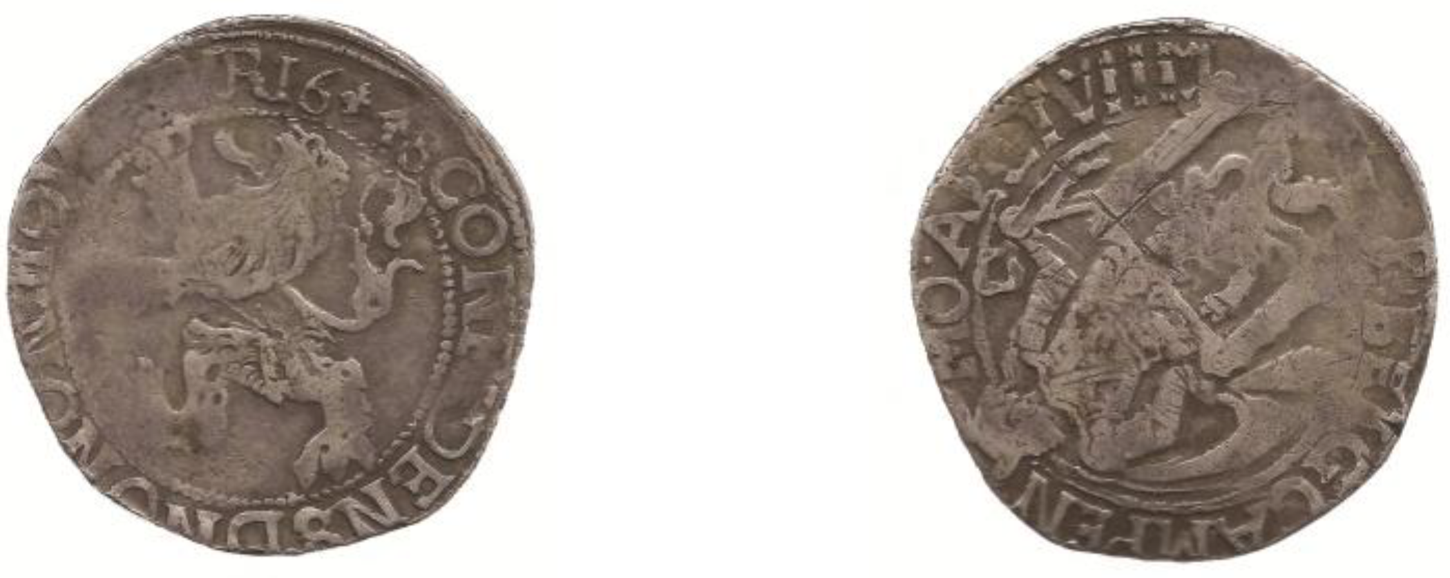
Figure 2.
The blank discs arrangement on the metal stripe.

Figure 3.
The perforated holes interference and curved clipped blanks appearance.
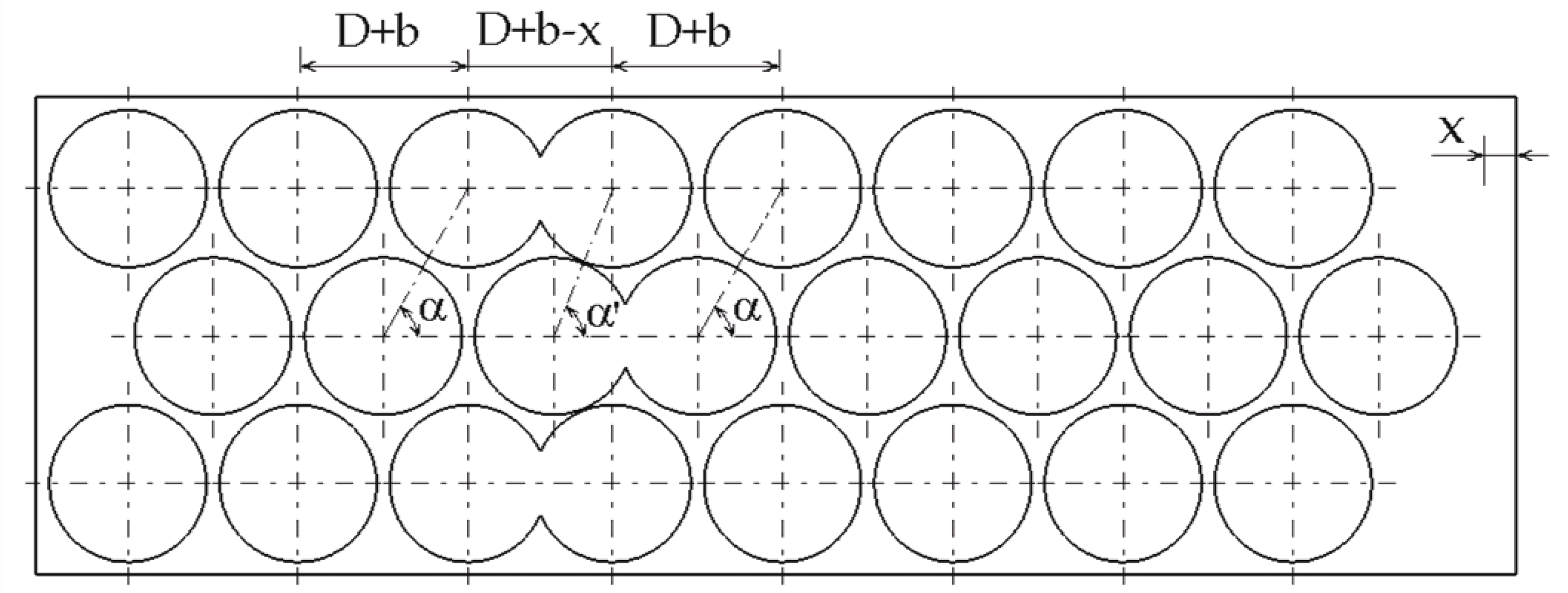
Figure 4.
The stripe angular misalignment and straight clipped blanks appearance.
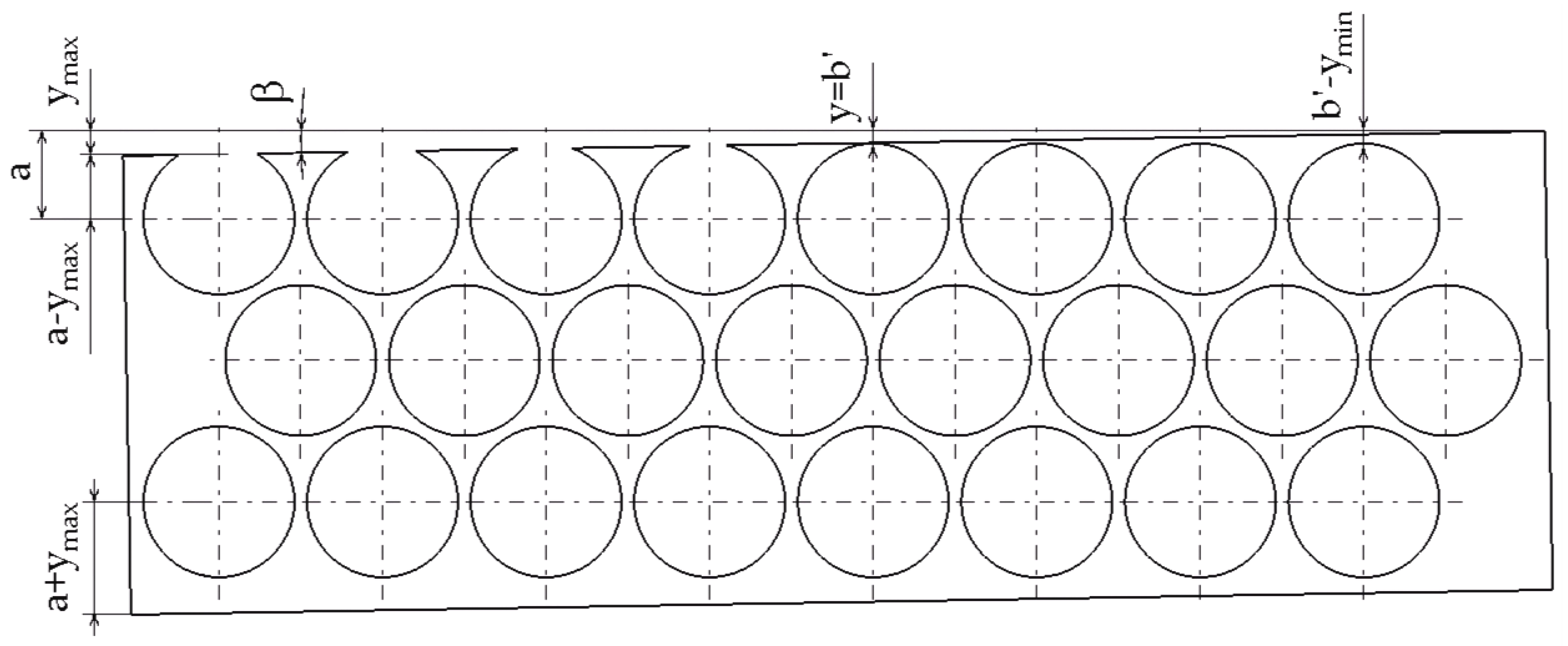
Figure 5.
The perforation outside the stripe end and straight clipped blanks appearance.
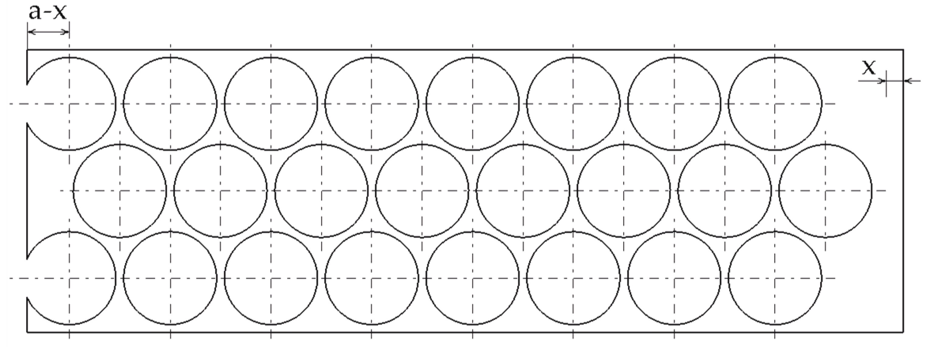
Figure 6.
Various coins having curved clips: (a) a former Myanmar 1 mat silver coin from 1853, (b) a former Spain 10 pesetas from 1992, (c) a Spain 50 eurocent from 1999, (d) a former Romanian 1 leu from 1947, (e) a former Romanian 1 leu from 1951 and (f) a former Romanian 10 lei from 1992.
Figure 6.
Various coins having curved clips: (a) a former Myanmar 1 mat silver coin from 1853, (b) a former Spain 10 pesetas from 1992, (c) a Spain 50 eurocent from 1999, (d) a former Romanian 1 leu from 1947, (e) a former Romanian 1 leu from 1951 and (f) a former Romanian 10 lei from 1992.
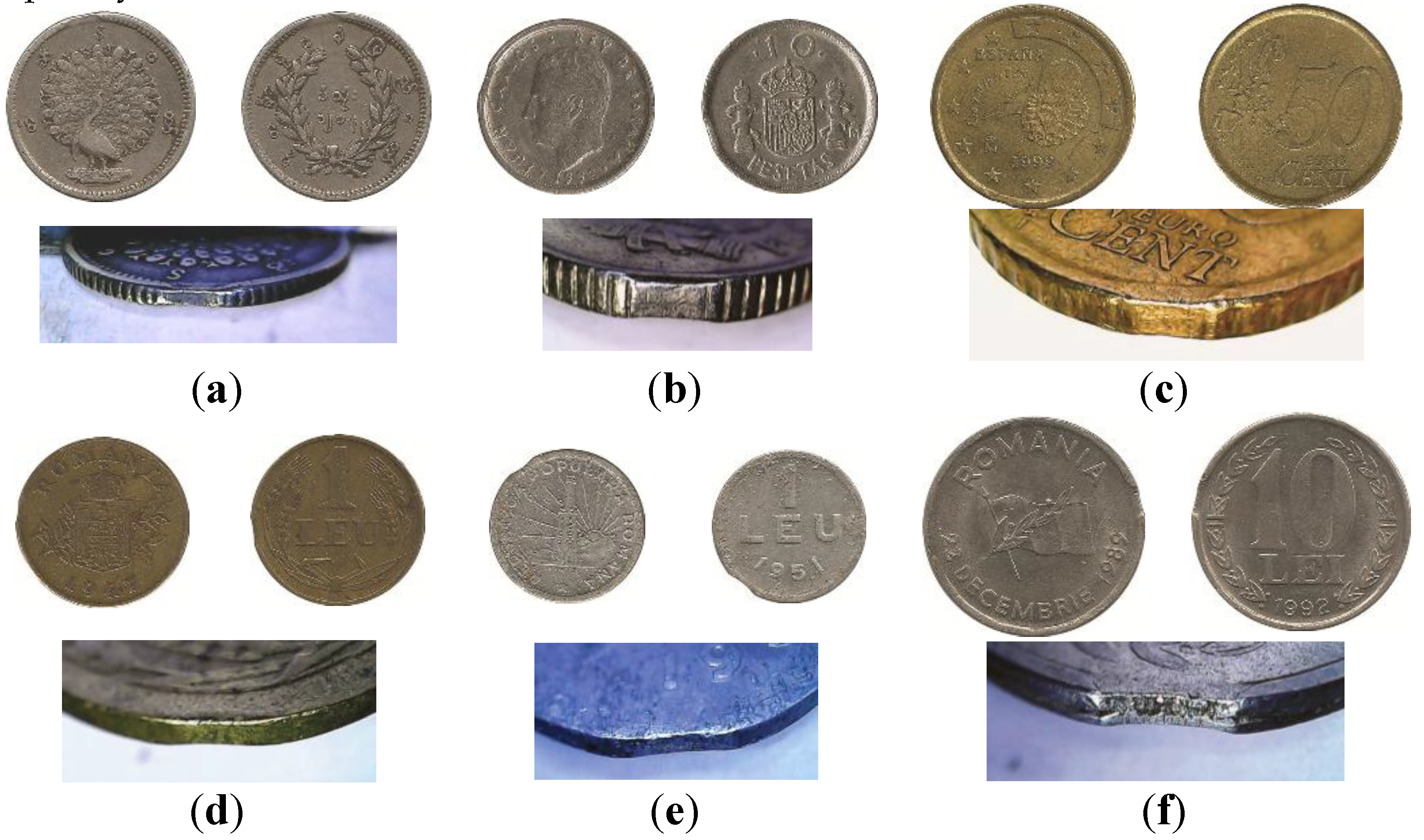
Figure 7.
Romanian coins having straight clips: (a) a former 100 lei silver coin from 1932 (b) and (c) two former 10 lei coins, from 1992.
Figure 7.
Romanian coins having straight clips: (a) a former 100 lei silver coin from 1932 (b) and (c) two former 10 lei coins, from 1992.
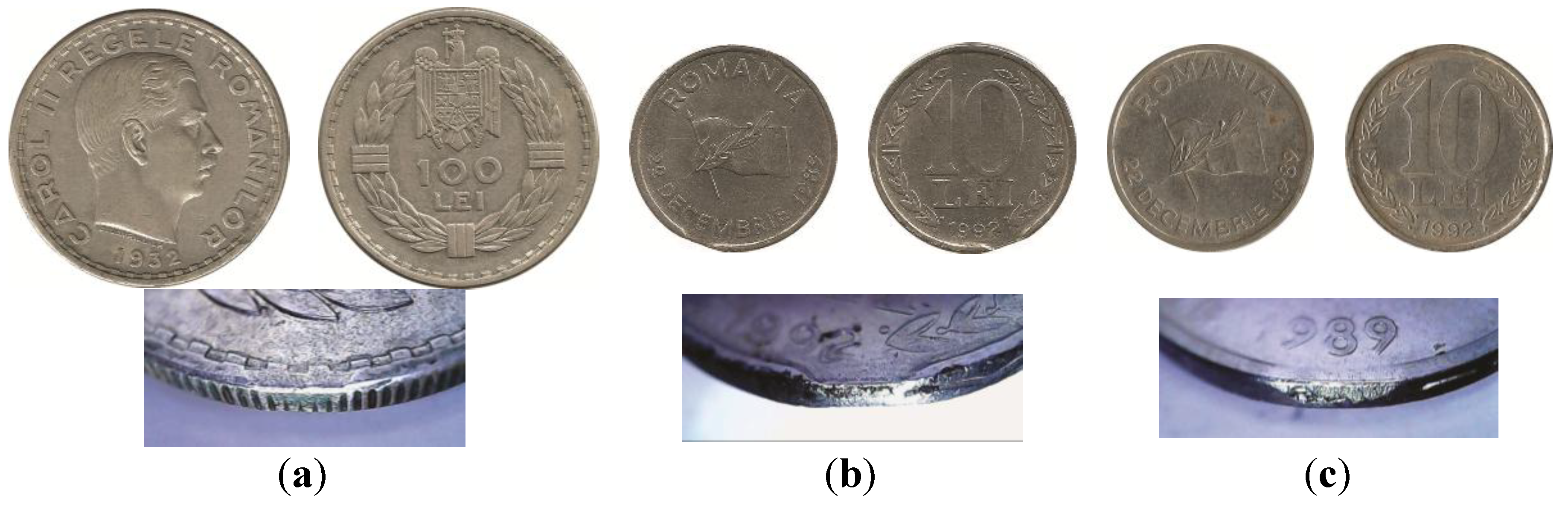
Figure 8.
Coins having ragged clips: (a) a former Romanian 1 leu from 1951 and (b) a former Chilean 100 pesos coin from 1995.
Figure 8.
Coins having ragged clips: (a) a former Romanian 1 leu from 1951 and (b) a former Chilean 100 pesos coin from 1995.
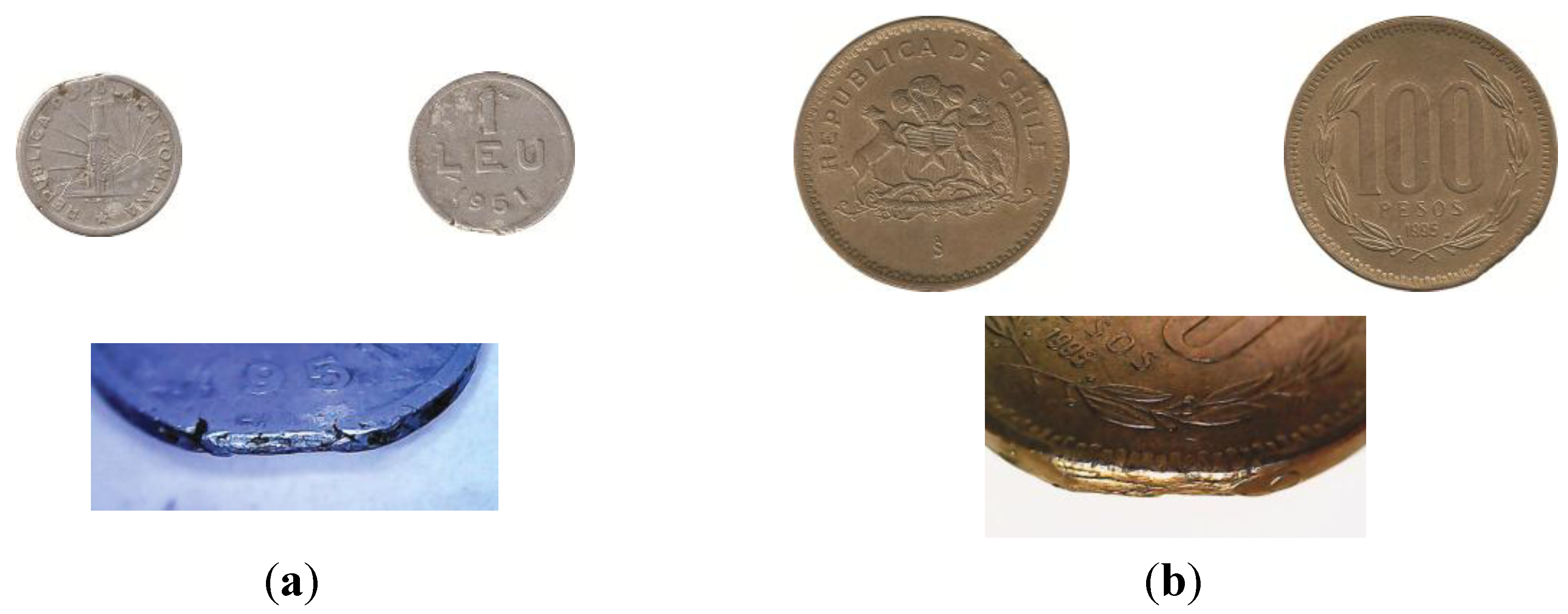
Figure 9.
The virtual model computed parts: (a) and (c) striking dies, (b) the collar, (d), (e), (f) the studied coins.
Figure 9.
The virtual model computed parts: (a) and (c) striking dies, (b) the collar, (d), (e), (f) the studied coins.
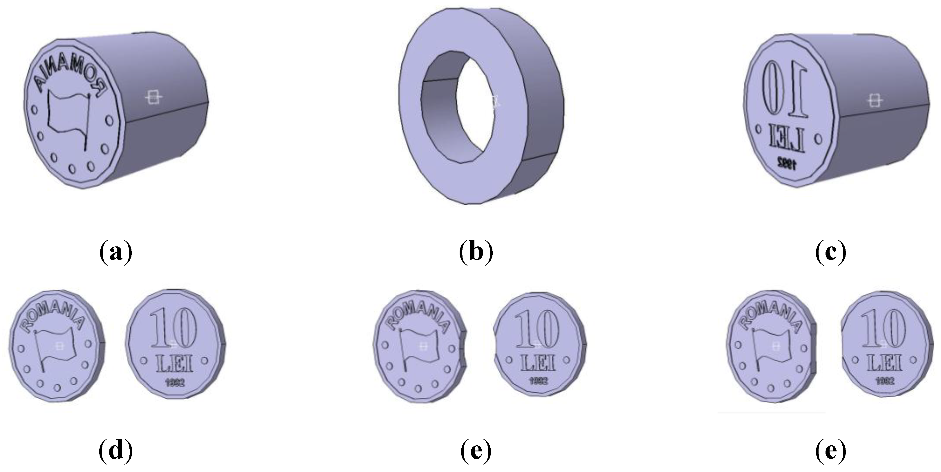
Figure 10.
The ensemble models: (a), dispersed components view, (b) assembled model view.
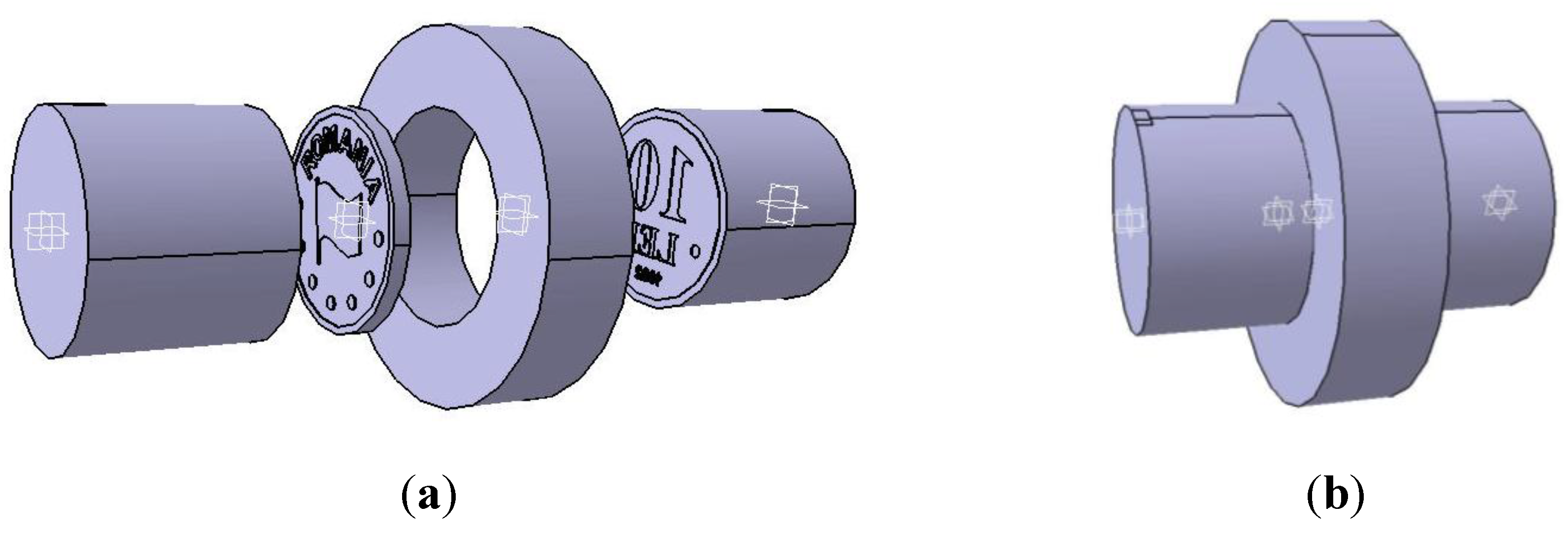
Figure 11.
The finite element model: (a), for unclipped coin, (b), for curved clipped coin, and (c), for straight clipped coin.
Figure 11.
The finite element model: (a), for unclipped coin, (b), for curved clipped coin, and (c), for straight clipped coin.
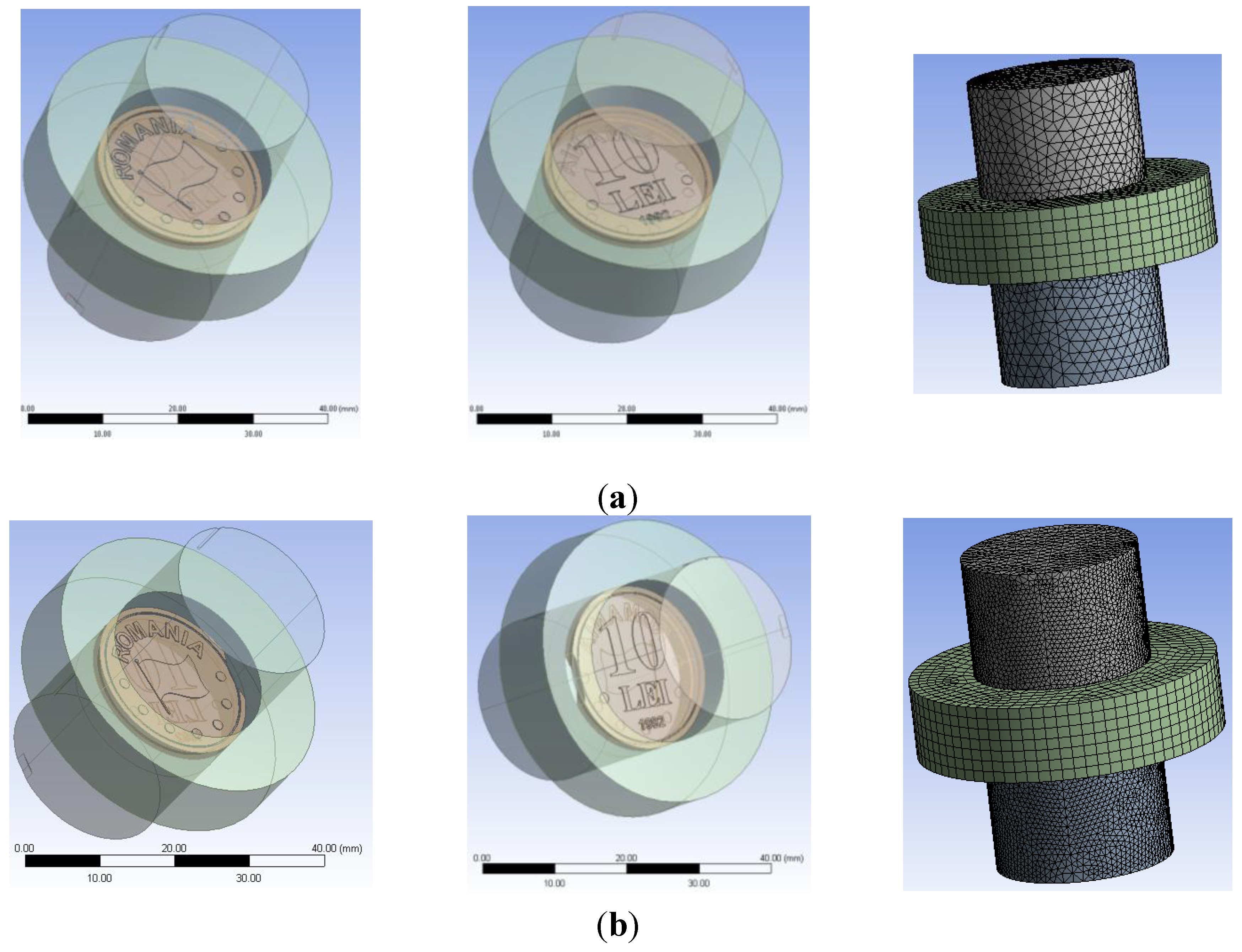
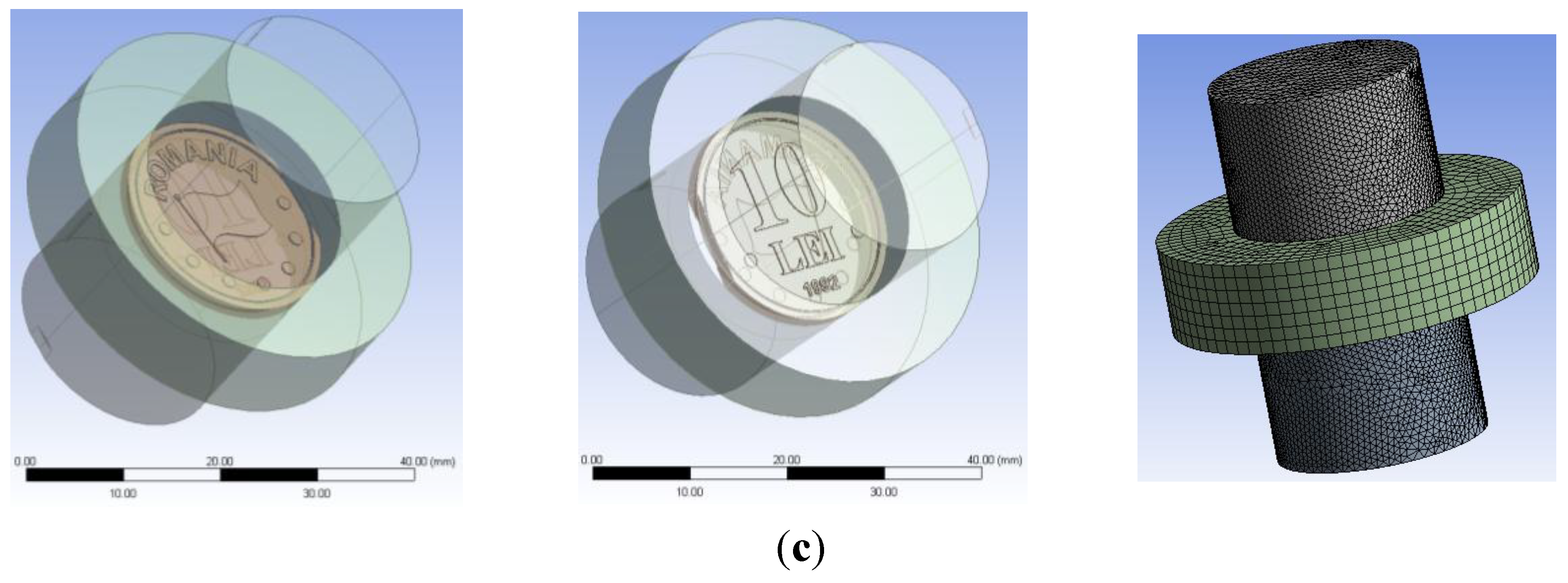
Figure 12.
The total deformation on the unclipped coin: (a) on coin obverse, (b) on coin edge and (c) on coin reverse.
Figure 12.
The total deformation on the unclipped coin: (a) on coin obverse, (b) on coin edge and (c) on coin reverse.
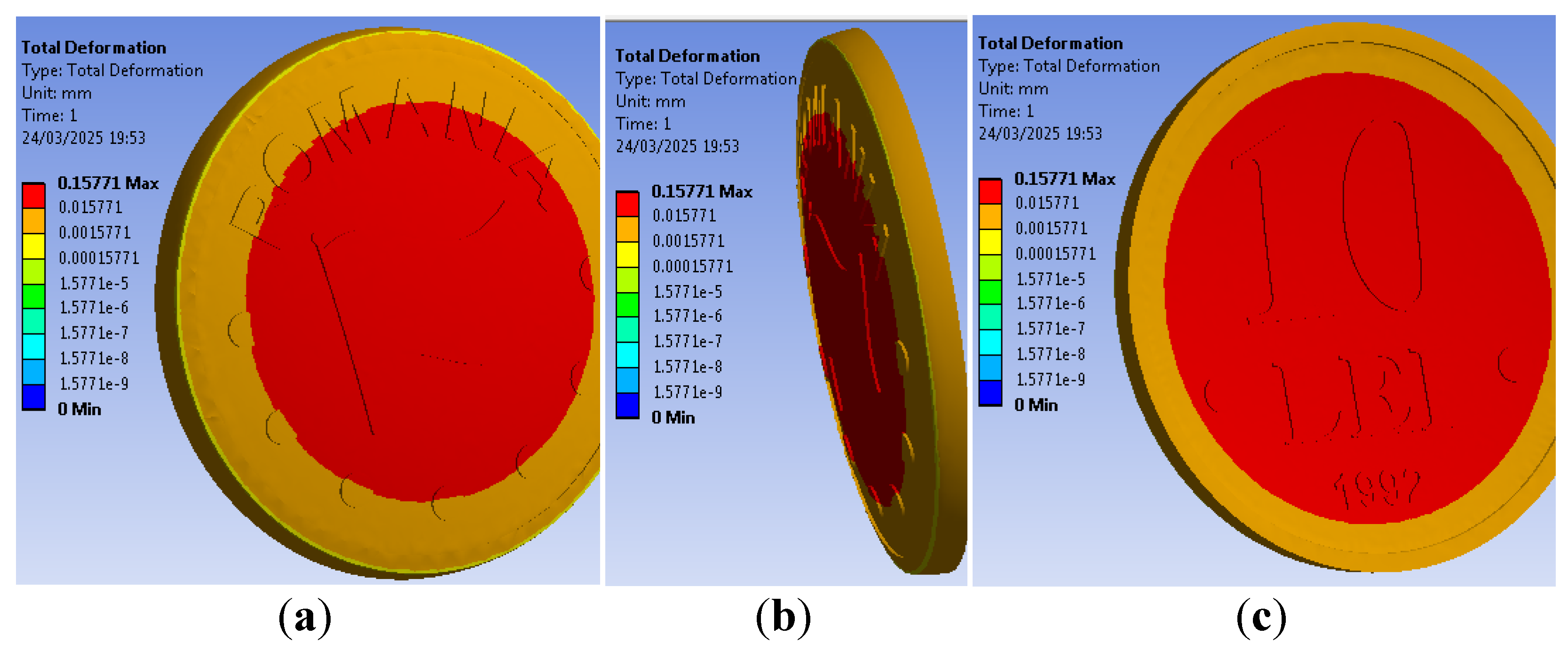
Figure 13.
The equivalent stress on unclipped coin: (a) on coin obverse, (b) on coin edge and (c) on coin reverse.
Figure 13.
The equivalent stress on unclipped coin: (a) on coin obverse, (b) on coin edge and (c) on coin reverse.
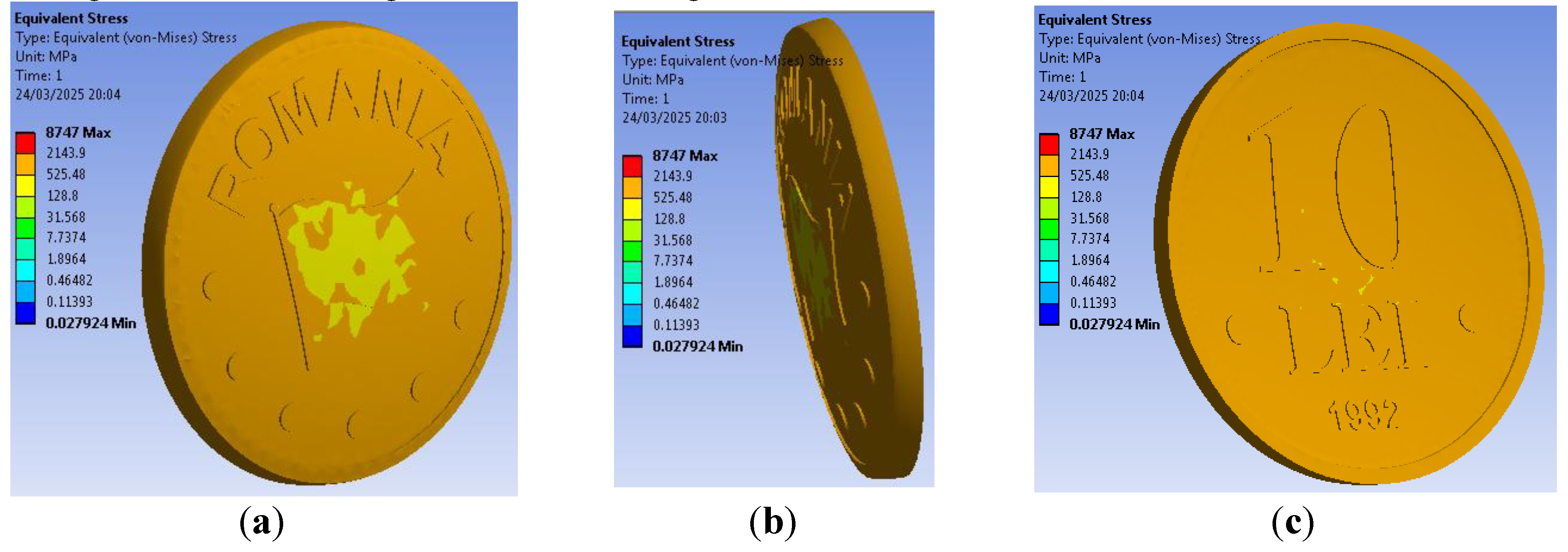
Figure 14.
The total deformation on curved clipped coin: (a) on obverse, (b) on the edge and (c) on reverse.
Figure 14.
The total deformation on curved clipped coin: (a) on obverse, (b) on the edge and (c) on reverse.
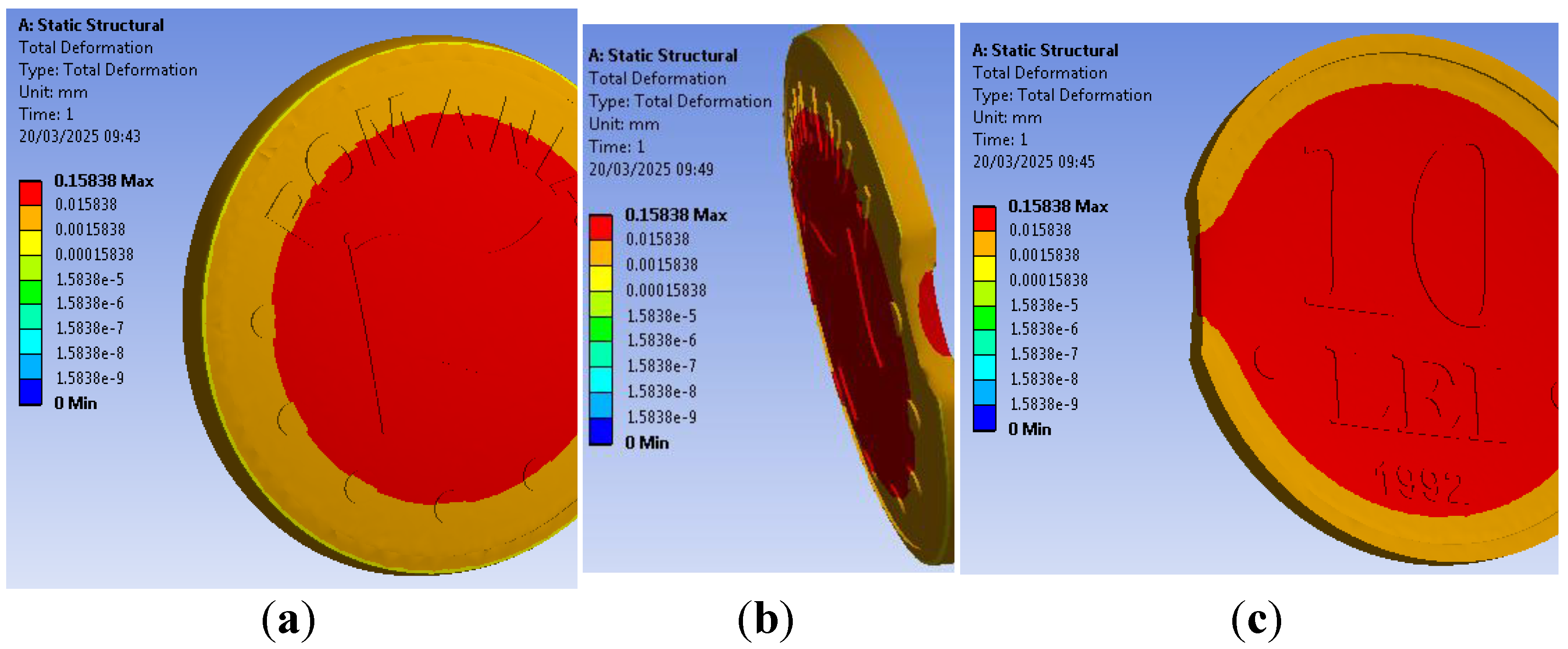
Figure 15.
The equivalent stress on curved clipped coin: (a) on obverse, (b) on the edge and (c) on reverse.
Figure 15.
The equivalent stress on curved clipped coin: (a) on obverse, (b) on the edge and (c) on reverse.
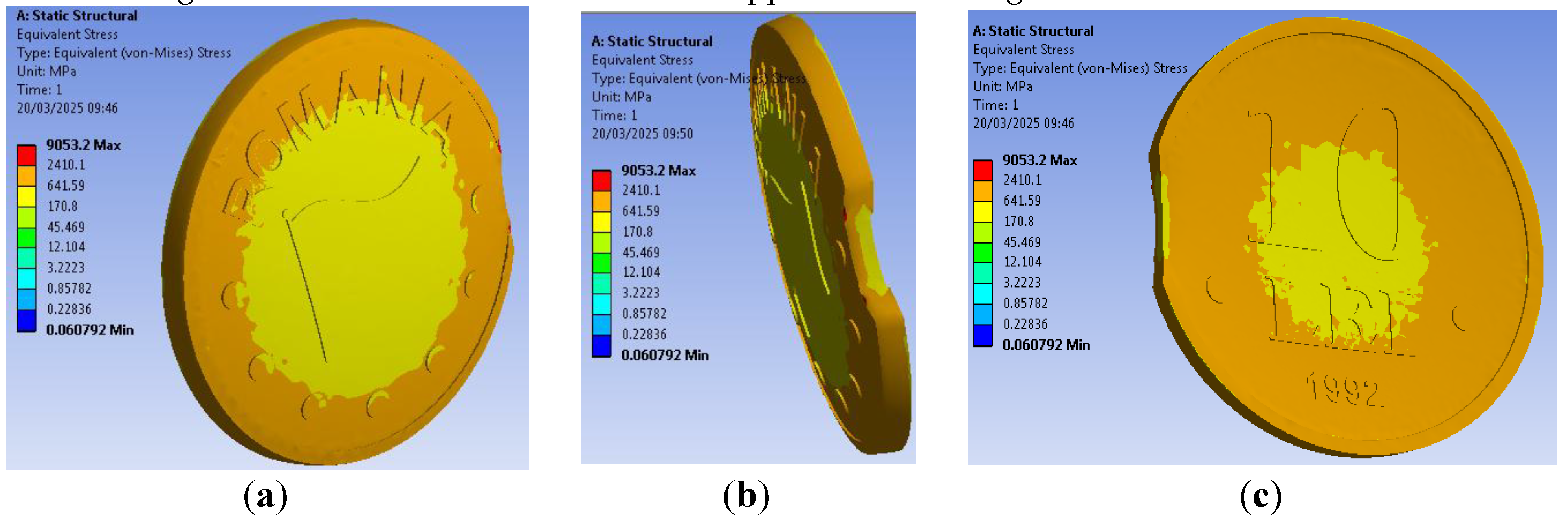
Figure 16.
Detail on curved clipped coin edge.
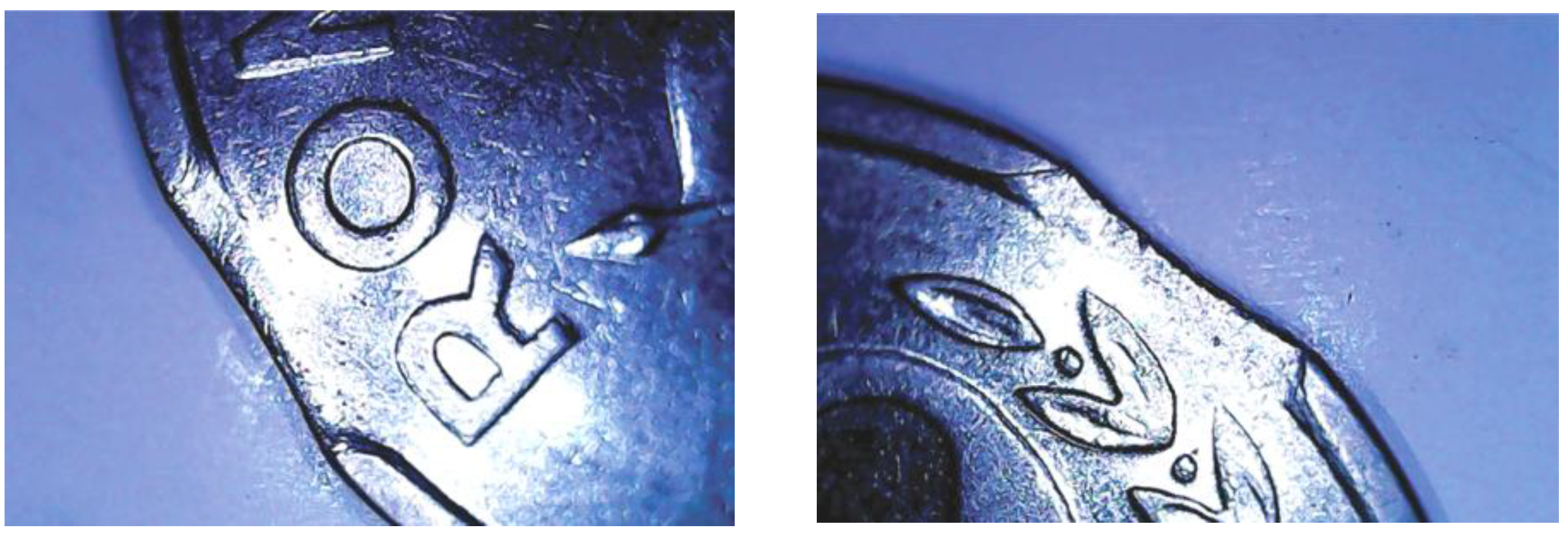
Figure 17.
The total deformation on straight clipped coin: (a) on obverse, (b) on the edge and (c) on reverse.
Figure 17.
The total deformation on straight clipped coin: (a) on obverse, (b) on the edge and (c) on reverse.
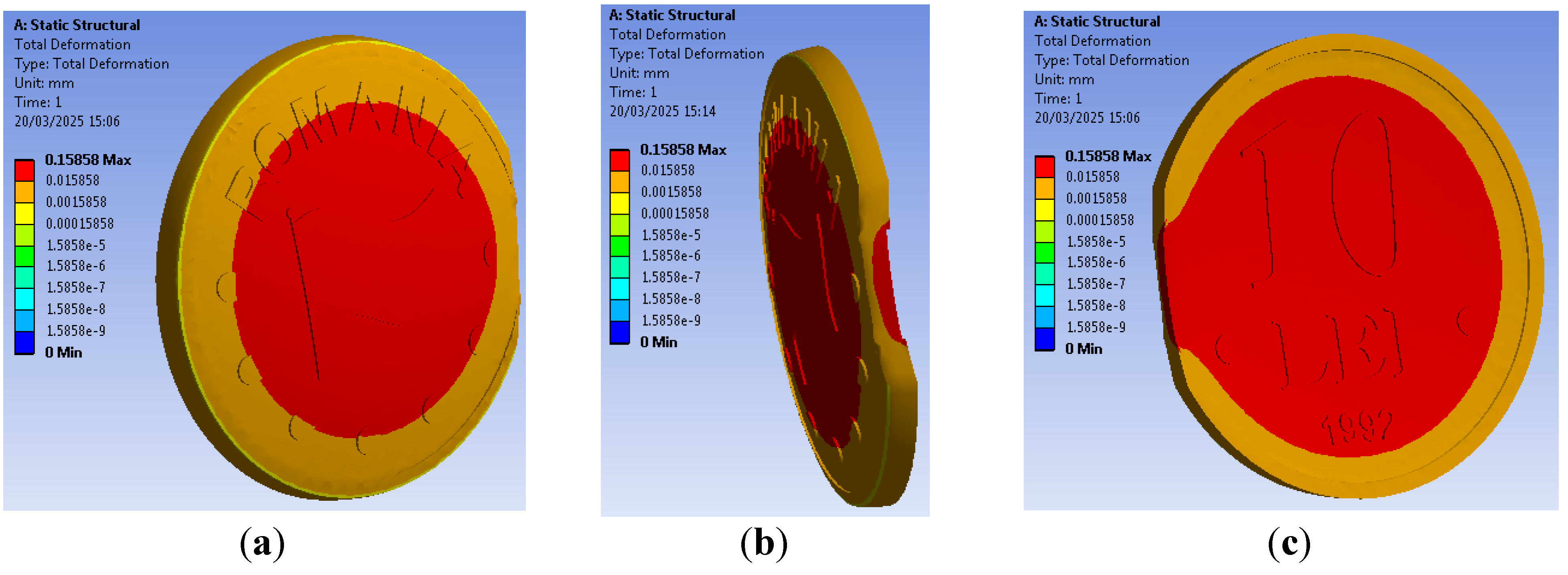
Figure 18.
The equivalent stress on straight clipped coin: (a) on obverse, (b) on the edge and (c) on reverse.
Figure 18.
The equivalent stress on straight clipped coin: (a) on obverse, (b) on the edge and (c) on reverse.
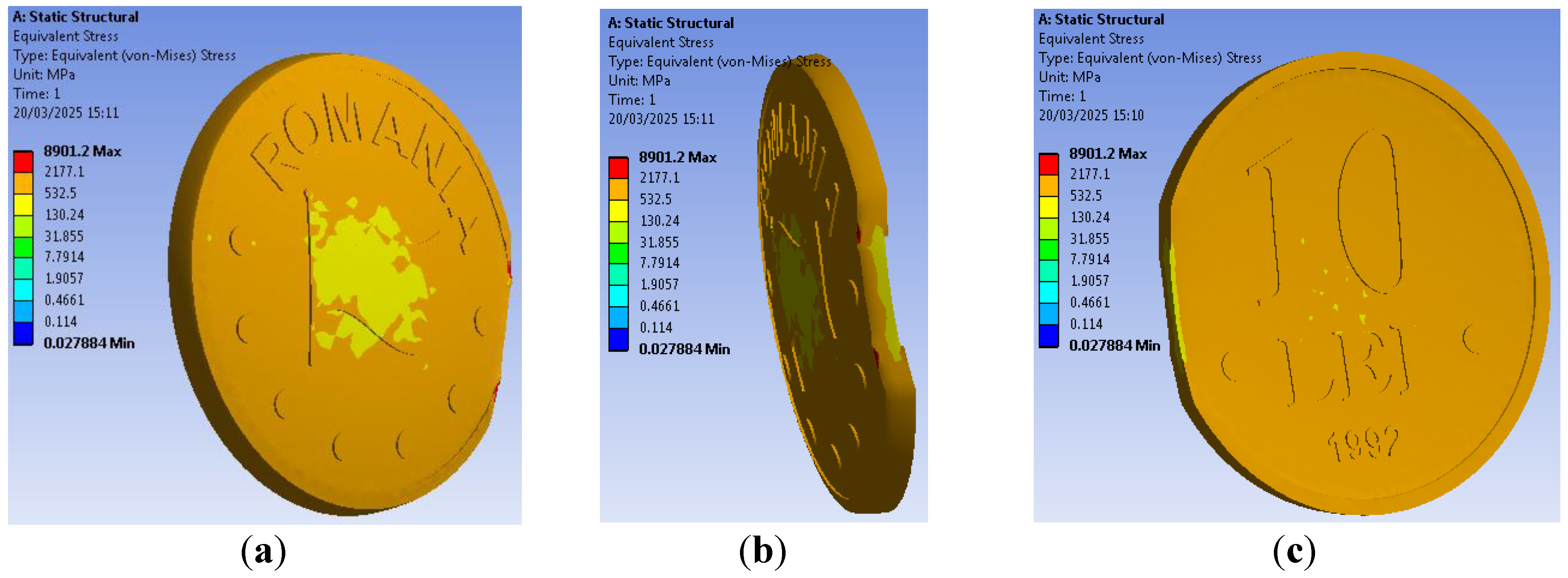
Figure 19.
Detail on straight clipped coin edge.
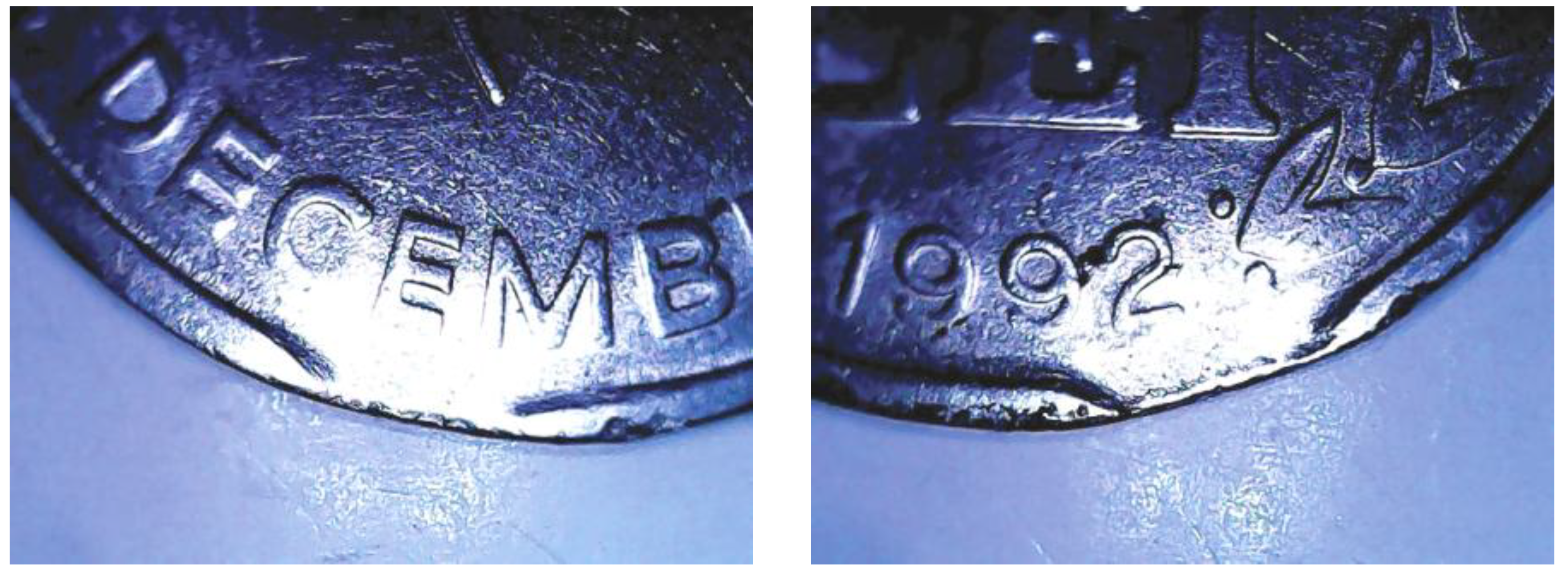
Figure 20.
Various former Romanian coins having small size clips: (a) a Romanian silver 500 lei from 1944, (b) a Romanian 50 bani from 1947 and (c) a Romanian 10 lei from 1992.
Figure 20.
Various former Romanian coins having small size clips: (a) a Romanian silver 500 lei from 1944, (b) a Romanian 50 bani from 1947 and (c) a Romanian 10 lei from 1992.
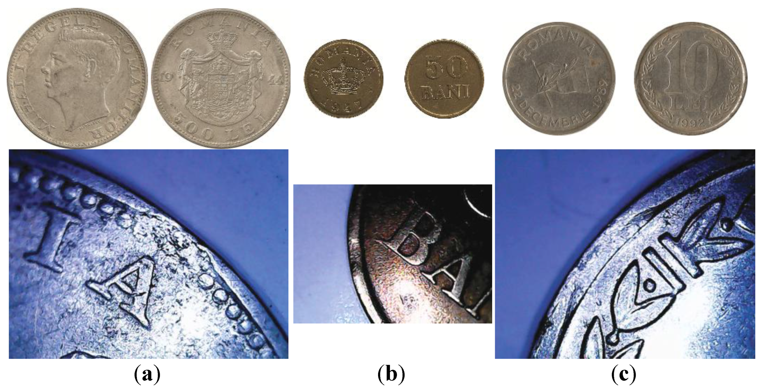

Table 1.
The considered steel mechanical properties
| Mechanical property | Mild steel | Hardened steel |
|---|---|---|
| Density, kg/m3 | 8000 | 7830 |
| Modulus of Elasticity, GPa | 200 | 250 |
| Tensile Yield Strength, MPa | 345 | 1250 |
| Tensile Ultimate Strength, MPa | 485 | 1600 |
| Poisson’s Ratio | 0.303 | 0.295 |
Table 2.
The total deformation and the equivalent stress maximum values.
| The coin type | Total deformation, mm | Equivalent stress, MPa |
|---|---|---|
| Without clip | 0,15771 | 8747 |
| With curved clip | 0,15838 | 9053.2 |
| With straight clip | 0,15858 | 8901.2 |
Table 3.
Contact area measurements on virtual model.
| The coin type |
Clip interfe- rence, mm |
Flat field area, mm2 | Engraved relief area, mm2 |
Edge rim area, mm2 |
Coin circumference area, mm2 | ||
| obverse | reverse | obverse | reverse | ||||
| Without clip | - | 275.793 | 302.134 | 83.888 | 57.547 | 55.795 | 130.062 |
| With curved clip | 1,15 | 274.876 | 301.217 | 83.888 | 57.547 | 51,178 | 116.915 |
| With straight clip | 1,15 | 274.522 | 300.953 | 83.888 | 57.547 | 49,299 | 111.389 |
Disclaimer/Publisher’s Note: The statements, opinions and data contained in all publications are solely those of the individual author(s) and contributor(s) and not of MDPI and/or the editor(s). MDPI and/or the editor(s) disclaim responsibility for any injury to people or property resulting from any ideas, methods, instructions or products referred to in the content. |
© 2025 by the authors. Licensee MDPI, Basel, Switzerland. This article is an open access article distributed under the terms and conditions of the Creative Commons Attribution (CC BY) license (http://creativecommons.org/licenses/by/4.0/).
Copyright: This open access article is published under a Creative Commons CC BY 4.0 license, which permit the free download, distribution, and reuse, provided that the author and preprint are cited in any reuse.


