
Submitted:
17 February 2025
Posted:
18 February 2025
You are already at the latest version
Abstract
Additive manufacturing (AM) is revolutionizing industrial manufacturing by introducing advanced techniques for designing and producing prototypes across various sectors. AM is increasingly being used to create cost-effective tools, such as blank holders, dies, and punches, that enhance the formability of sheet metal products. This study investigates the use of 3D-printed tools in the V-bending process, employing Finite Element Analysis (FEA) and experimental setups at angles of 30, 45, and 60 degrees. The formability of 1mm-thick SS304 steel and AA6061 aluminium was evaluated, focusing on geometric precision, thinning, and overall formability. FEA results suggest that increasing sheet thickness may reduce formability for both materials. Simulations were compared with permissible limits to ensure accurate samples. Experimentally, sixty samples were bent using dies and punches made from Acrylonitrile Butadiene Styrene (ABS). Results showed that the ABS material significantly influenced the bending process, indicating its potential for use in batch production. The findings highlight the feasibility of using AM-generated tooling to improve formability and optimize production in sheet metal forming.
Keywords:
Formability
; Fusion Deposition Modelling
; 3D Printing
; Additive Manufacturing
; bending operation
1. Introduction
Forming sheet metal components is a common industrial process. Traditionally, it involves cutting raw materials into the required shape and size, fabricating tools, and forming components into the desired geometry. This process achieves favourable outcomes only when components are manufactured with zero error and minimal material wastage. Today’s manufacturing follows a holistic approach that encompasses multiple production stages, addresses customized demands, ensures material properties, and anticipates future challenges in the production process [1]. Additive Manufacturing (AM) is revolutionizing these conventional methods by enabling rapid prototyping, which accelerates design iterations and allows for the creation of complex geometries that are difficult to achieve with traditional techniques [2]. AM is particularly useful in integrated component repair via reverse engineering, allowing precise reconstruction and enhancement of damaged parts to extend their lifespan [3]. The technology is widely used in industries such as automotive, medical devices, and human-machine interfaces, where it produces lightweight, high-strength components and customized parts [4,5].
This study focuses on utilizing Finite Element Analysis (FEA) to assess formability and the development of a V-bending tool through AM [6]. In conventional V-bending, metal dies and punches are used for bending at various angles, where the tooling contacts the sheet at three points: the punch tip and the die shoulders. Bottoming involves pressing the material fully into the die cavity, and coupling the punch, sheet metal, and die together. Tool steel dies are typically used for longevity, but frequent replacement is not cost-effective for customized profiles or small batch production. AM offers flexible tooling solutions, which can replace traditional systems to meet dynamic product demands [7]. Fused deposition modeling (FDM), stereolithography (SLA), and selective laser sintering (SLS) are some of the reliable AM techniques commonly used in the industry, utilizing liquid polymers and powders to create prototype models [8,9]. Figure 1 provides an overview of these AM techniques.
Bergonzia et al. explored the influence of build parameters in additive manufacturing (AM) on bonded joint design factors. Their study focused on the parametric impact on polymer-bonded joints to determine toughness, using PLA (Polylactic acid) and ABS (Acrylonitrile Butadiene Styrene) materials. Testing for roughness, wettability, and tensile strength was conducted, and Taguchi L9 was applied to design experiments. The findings indicated that AM process parameters significantly affect fracture toughness and optimal toughness can be achieved by adjusting the setup [10].
Sargini et al. investigated the additive manufacturing of an automotive brake pedal using metal FDM. The study demonstrated the potential of AM to produce metallic brake pedals with flexible designs, utilizing BASF Ultrafuse 316L filament. Finite element analysis (FEA) confirmed the brake pedal’s viability and prototype testing verified smooth operation [11]. AM-integrated casting effectively meets customized demands in advancing technologies achieving the required efficiency [12]. Pujante et al. compared 3D-printed dies made from maraging steel 1.2709 with conventional tool steel H13 for press machines. After 800 hot stamping strokes, wear and thermal performance analyses showed that 3D-printed tools can be successfully used in die production [13] N. Naveed et al. studied the effects of process parameters on material properties, identifying that raster patterns and angles significantly influence 3D-printed parts. Scanning electron microscopy (SEM) revealed defects and fracture areas in the samples [14]. Giorleo et al. researched the use of polymer punches in aluminium deep drawing, concluding that elastic and plastic deformation of polymer punches affects the formability of cups [15]. Schuh et al. have carried out experimental work for cup forming of steel-grade material using PLA plastic tools, the outcomes suggest that FEA can be a useful tool to predict the deformation failure in tools in the initial stage of forming. Secondly PLA material can effectively form the cup in simulation and experimental results [16]. Nakamura et al. have discovered that sheet metal may be bent with the help of plastic tools. Elastic deformation during bending increases the angles of the plastic punch and die, and the products’ angles are higher than those of the steel tools. Bending with a plastic die and steel punch works well to increase the items’ dimensional correctness [17].
Klimyuk et al. investigated the use of 3D printing technology for quick tooling in sheet metal forming for small-lot or custom manufacturing It was found that the primary issue with using 3D printing technology for die tooling is that it might be constrained by the low proportionality limit of 3D-printed material. To demonstrate the difficulty of anticipating proportionality limits, several specimens printed with various process parameters were evaluated. An aluminium sheet was successfully drawn using a plastic punch and die that was produced [18].
Bachmann et al. investigated the mechanical comprehension of the procedure the algorithms used to create their laser scan patterns and the effective laser origami of intricate 3D structures. Choosing whether laser forming is the ideal production method necessitates design heuristics that are yet unclear, just like with any other prototyping technology. To expand the capabilities of laser forming and make it a reliable technology capable of producing functional, nearly arbitrary 3D structures from flat substrates in an automated manufacturing environment [19].
Tondini et al. demonstrate the V-bending process in terms of tools altering the surface topography while forming, reaching a stable state after five strokes. When bending to 90° with three distinct punch nose radii, the spring-back angle and the resulting bend radius are used to assess the geometrical correctness achieved in V-bending. The elastic deflection of the tools exhibits additional effects on the spring-back, and the printing strategy is found to have an impact on the punch nose radius because of the ratio of the tool radius to the thickness of the printed solid shell that encloses the otherwise less dense bulk part of the tool [20].
Dengiz et al. A comparison has been made between various methods for simulating bimetallic sheets using the finite element (FE) approach. To identify the FE model that produces the most realistic outcome, sheets modelled under five distinct assumptions were compared to one another and experimental data. The model developed under the presumption that there is a solidified adhesive layer in the intermediate layer and an adhesion interface between this layer and metallic layers produced the values that were most similar to the experimental findings [21].
Taşkın et al. investigated the deep drawing process modelled in Abaqus/Explicit finite element (FE) software and was experimentally tested and the design factors of square medical containers were identified. To cut down on the number of experiments, the Taguchi statistical method was applied. When choosing thickness reduction (TR) and maximum punch force (PF) as output parameters, the following variables were chosen as variables: blank holder force (BHF), punch radius (RP), die radius (RD), coefficient of friction between die and blank (µDB), coefficient of friction between punch and blank (µPB), and coefficient of friction between holder and blank (µHB). ANOVA analysis was utilized to ascertain the impact of variable factors on the output parameters [22].
This study introduces an approach of tooling for metal forming processes by utilizing ABS 3D-printed tools specifically tailored for V-bending operations on SS304 and AA6061. While earlier studies have demonstrated the feasibility of using ABS tools for forming processes, they often focus on limited bending angles or lack a comprehensive evaluation of formability and dimensional accuracy. This study advances the field by integrating FEA with experimental validation across multiple bending angles (30°, 45°, and 60°), providing a more holistic assessment of ABS tool performance. Unlike previous research, this work uniquely explores the formability, dimensional precision, and cost-efficiency of ABS tooling as a feasible alternative to conventional methods. By integrating FEA simulations with experimental validation, the study provides insights into the performance and durability of ABS tools, offering an innovative solution for flexible and cost-effective manufacturing, particularly suited for small to medium-scale production scenarios.
2. Material and Methods
Formability Analysis of the V-Bending Process
In the initial phase of the current study, a static model is used of FEA simulations of V-bending operations for three angles 30, 45, and 60 degrees using two material grades, SS304 (Stainless steel 304) and AA6061 (Aluminium alloy 6061). These angles are commonly preferred in standard sheet bending applications [23]. Investigating material formability during the forming process is crucial for the error-free production of new products [24]. FEA, with its ability to reduce lead time and cost while providing accurate formability results, offers an essential pre-production evaluation for sheet metal processes. Its capacity to simulate a wide range of materials enables the assessment of potential effects in advance, improving actual production through tool path generation and simulation [25,26]
The FEA simulation of V-bending begins with inputting parameters such as blank and tool material, alignment, and the selected operation. The second step defines the process parameters such as punch force, friction and contact between die, sheet and punch which is based on the material’s anisotropy and mechanical properties, while also fixing the bending direction. The adaptive mesh size was considered for the model and dry condition for friction was considered for surface-to-surface contact for bending operations The third step involves verifying results for thinning, formability, and dimensional accuracy to identify potential errors, such as springback, thinning, and cracks [27]. Table 1 presents the input parameters used for the FEA simulations of V-bending operations.
As shown in Figure 2 the stress-strain relationship for Aluminium 6061 suggests significant plastic deformation before failure. Initially, the curve rises steeply, showing the elastic deformation phase where stress and strain are proportional called a linear region. As strain increases above 0.2 the curve starts to bend, indicating the beginning of plastic deformation. In this phase, the material deforms permanently. The stress continues to increase with strain, showing strain hardening at 0.89, where the material becomes stronger as it is deformed.
Table 2 presents the theoretical calculations for the precise dimensions and force required to bend a specific angle for a given material. The punch force is determined by multiplying the stress generated during bending with the area corresponding to the bending length. The bending coefficient, which depends on the sheet metal’s length and thickness, is also factored in. Among these, the bending length plays a significant role. Another critical factor is the bend allowance, which is calculated based on the bend angle and the required bend radius. Impact of Coefficient K, a higher value of K requires more force due to thicker sheets or tougher materials, lower K found in ductile or thinner materials, reducing force requirements. These calculations serve as a reference to verify both the process and geometric parameters [28,29].
Where,
– Coefficient =1.2=L=16t
B= Bending Length
t=Thickness
= Tensile Strength
L= Width of sheet
R=Radius
K=0.33 (R<2t)
The maximum percentage of thinning observed in the simulation results for SS304 and AA6061 is around 5% for all three angles, which is significantly lower than the standard acceptable limit of 20%. Observations from the forming limit curve (FLC), are used to predict the forming behaviour of sheet metal. The forming limit curve (FLC) separates safe and failure regions indicating that both materials can be bent safely at all three angles without major errors. Table 3 summarizes the forming limit curve for V-bending operations for SS304 and AA6061 materials [30,31].
3. Results and Discussion
3.1. Stress Analysis of Die and Punch for V Bending Operations
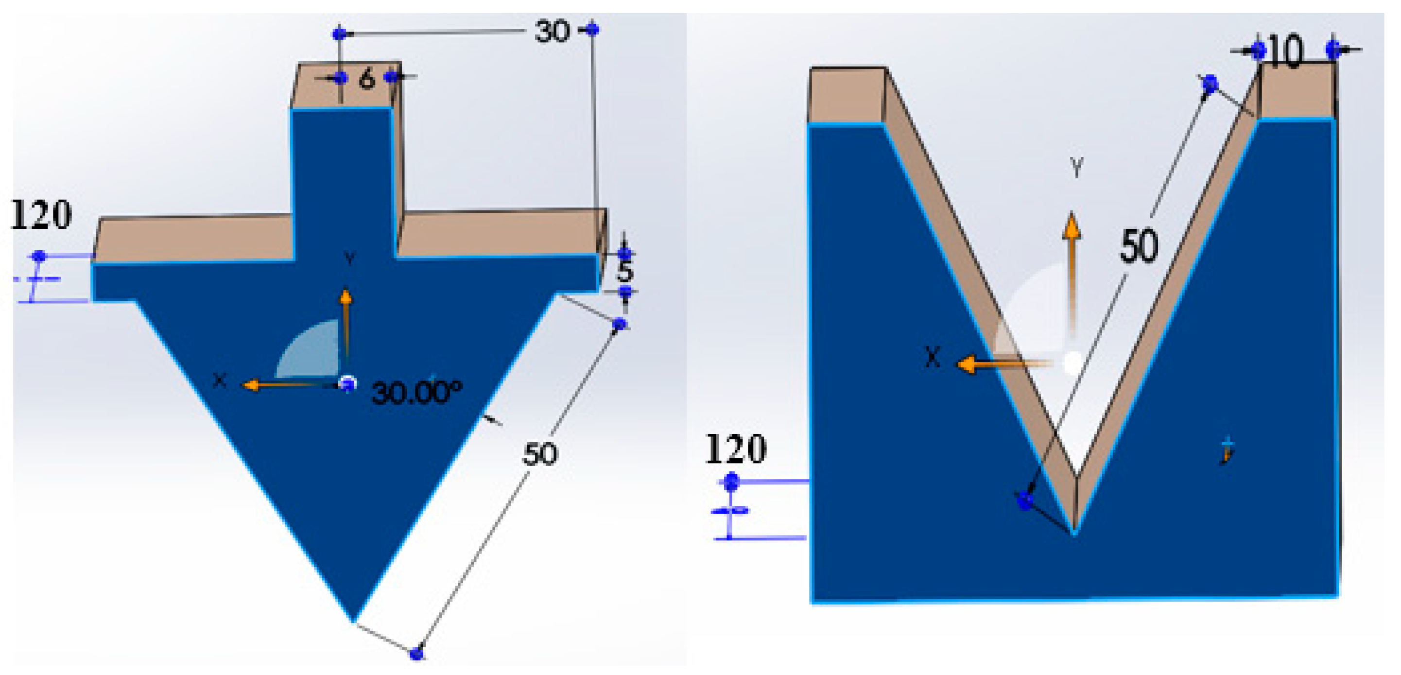
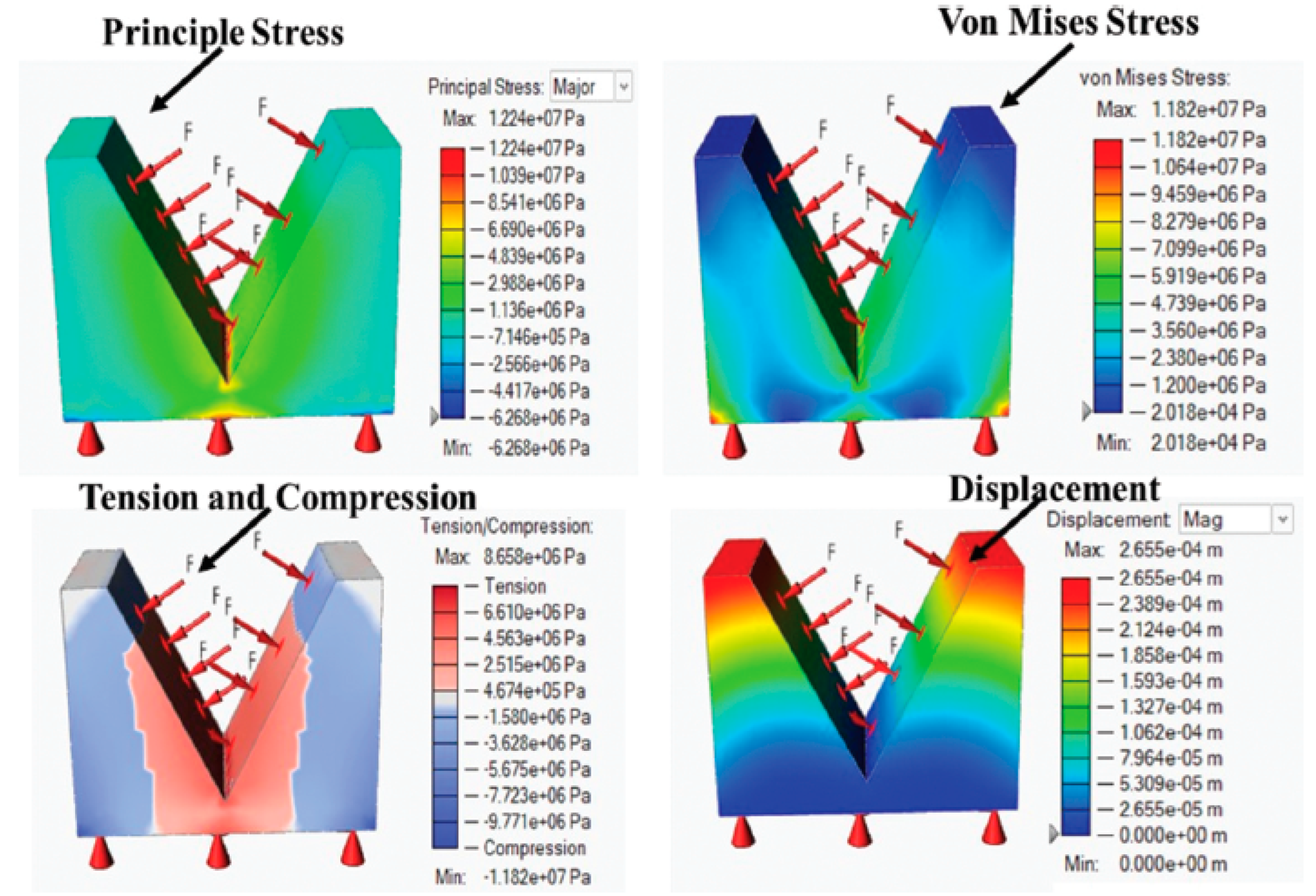
The properties of the dies used in the simulations for the V-bending punch and die are designed considering the characteristics of ABS material and the V-bending press. The dies are made of ABS (Acrylonitrile Butadiene Styrene), an engineering-grade thermoplastic known for its rigidity, impact resistance, and thermal resistance ABS material was selected for its ability to withstand bending forces and its permissible stress limits, making it suitable for the 3D printing of tooling components. For design considerations, the 60° V-bending angle was chosen for the punch and die as it requires the highest punch force. As shown in Fig. 3 the geometry of tools having a length of 120mm is considered for analysis. This is important because the V-bending process generates concentrated forces, especially when working with thicker or stronger materials. In the model, the upper flange of the punch is fixed, which simulates the real-world condition where the punch remains stationary while the load is applied. A dynamic stress analysis was conducted on both the punch and the die to evaluate the stress distribution and dimensional changes during the V-bending process. The simulation involved applying maximum punch forces ranging from 5 kN to 10 kN to replicate real-world operational conditions. The load was applied uniformly across the punch surface to simulate realistic conditions and assess the punch’s response to stress. For ABS, the tensile strength is approximately 40–50 MPa, while the flexural strength is around 70.5 MPa. The simulation results confirm that the 30° V-bending punch and die made of ABS material can handle the applied punch forces. The maximum principal stress of 17.60 MPa is within the safe limits for ABS at the upper flange, indicating that the tooling design will perform effectively without failure during V-bending operations [32,33]. Fig. 4 shows the stress points on the punch geometry. The bending angle geometry could be affected by increased compression caused by sudden loads and spring back in the sheet metal after multiple bending cycles. The analysis indicated that the bottom of the punch showed minimal skid marks; however, excessive skid marks could lead to tool wear and friction, impacting geometric precision. Both steel and aluminium sheets were successfully bent to the required angles. Fig. 5 shows the stress analysis of the die for the V-bending process. The principal stress around 5MPa observed in the simulations remained well below these limits, indicating no damage to the material. A displacement of 0.265 mm was observed on the upper side surface. The stress analysis highlights that while the punch remains largely unaffected, the die experiences some compression and potential long-term displacement. ABS material features exhibit higher compressive and shock-absorbing capacity compared to PLA material. The deformation and stability of tools are disturbed after more bending cycles as discussed by Zaragoza in his study of air bending applications. The high-temperature resistance material enables it to withstand friction and heat generated during the forming process, secondly, ABS plastic if used with composites and cured at optimised temperature can easily form thick sheets in the metal forming process as discussed by T. Sathish in his study of designing industrial component by 3D printing [34].
Figure 3.
Geometry of V die and Punch.
3.2. Properties Evaluation for Steel and Aluminium Material
Before initiating the experimental setup for the bending process, a standard spectroscopy test was conducted using ASTM E1251-2017a and ASTM E1086-2022 methods to evaluate the chemical content of both materials. The results confirmed that the elements in AA6061 and SS304 conform to the required chemical specifications. Table 4 presents the chemical composition of both material grades [35].
Figure 4.
Stress analysis results of punch for the V-bending process.
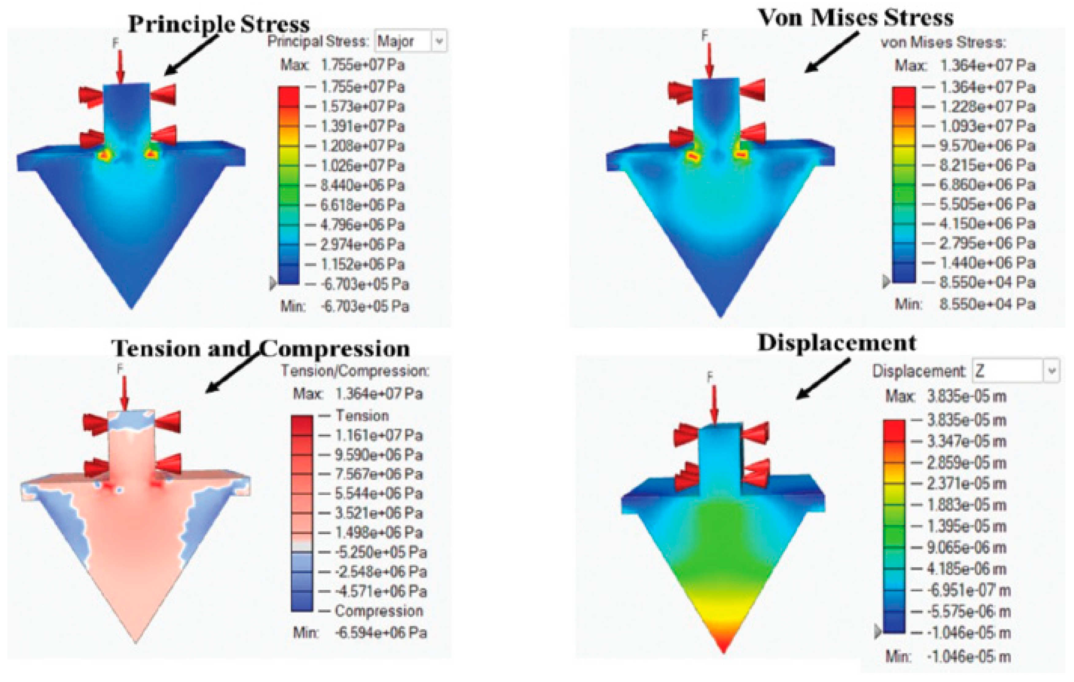
Figure 5.
Stress analysis results of die for V bending process.
4. Experimental Setup for V-Bending Process
4.1. 3D Printing of Tools
Dies and punches for V-bending operations are fabricated using an industrial-grade 3D printer and engineering-grade ABS material. ABS was chosen for its exceptional properties, including high impact resistance, stiffness, and temperature resilience, which distinguish it from other plastic polymers. The flexural strength of ABS, approximately 70.5 MPa, ensures the tools’ durability. Additionally, the process adheres to ISO Standards 527 and 1133, confirming the reliability and quality of the produced equipment.
The dies and punches used in this study were fabricated using an extrusion-based 3D printer. Key printing parameters were as follows: nozzle temperature of 220–230°C, table temperature of 60°C, fan settings optimized for cooling at moderate speed, and a layer thickness of 0.2 mm. The filament used was ABS with a diameter of 1.75 mm. The infill density was set at 70% to ensure a balance between structural integrity and material efficiency. The print speed was maintained at 45 mm/s, ensuring high dimensional accuracy and surface quality, as illustrated in Fig. 6, making them well-suited for bending operations [36].
Figure 6.
3D printing of die and punch.
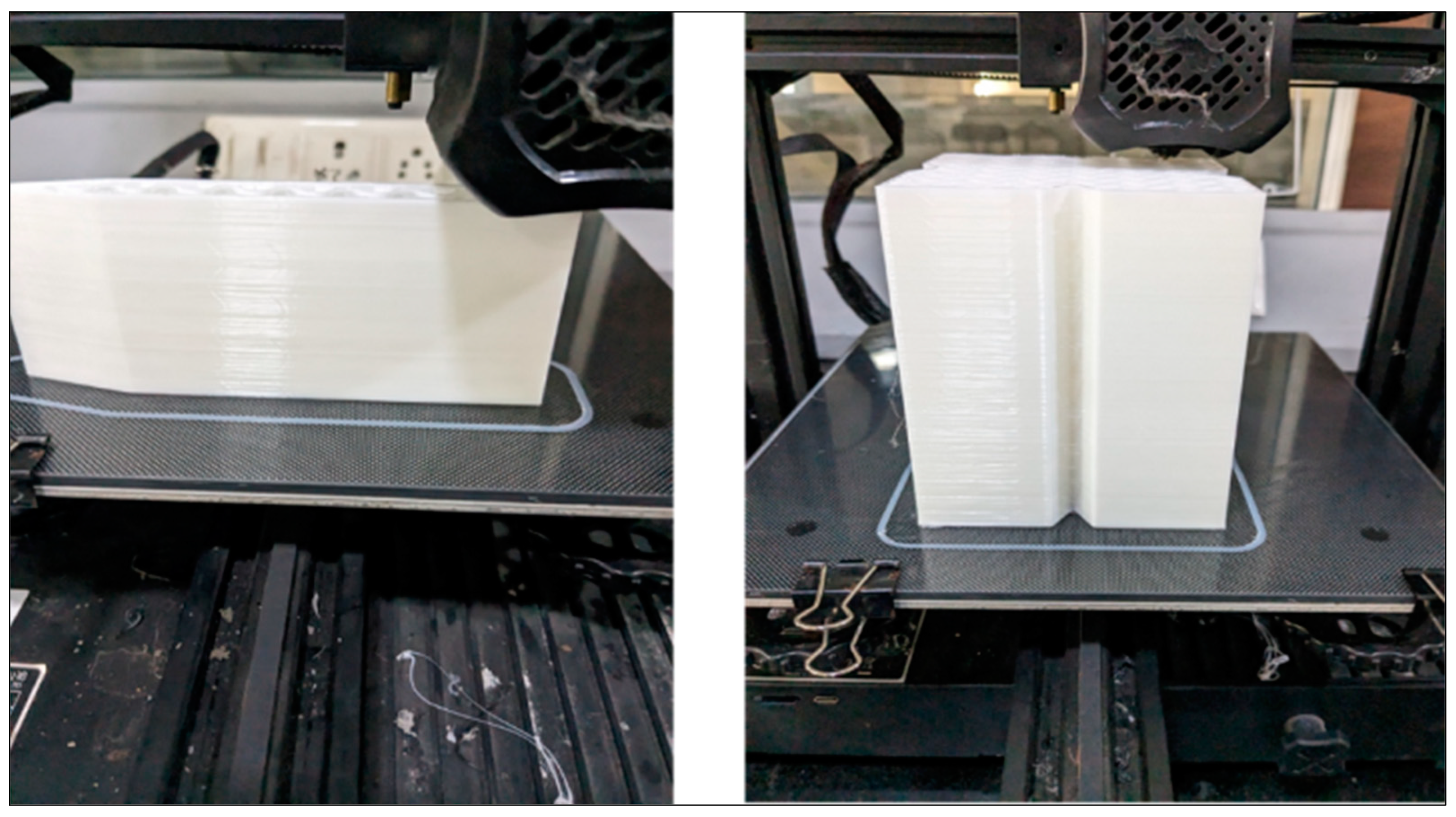
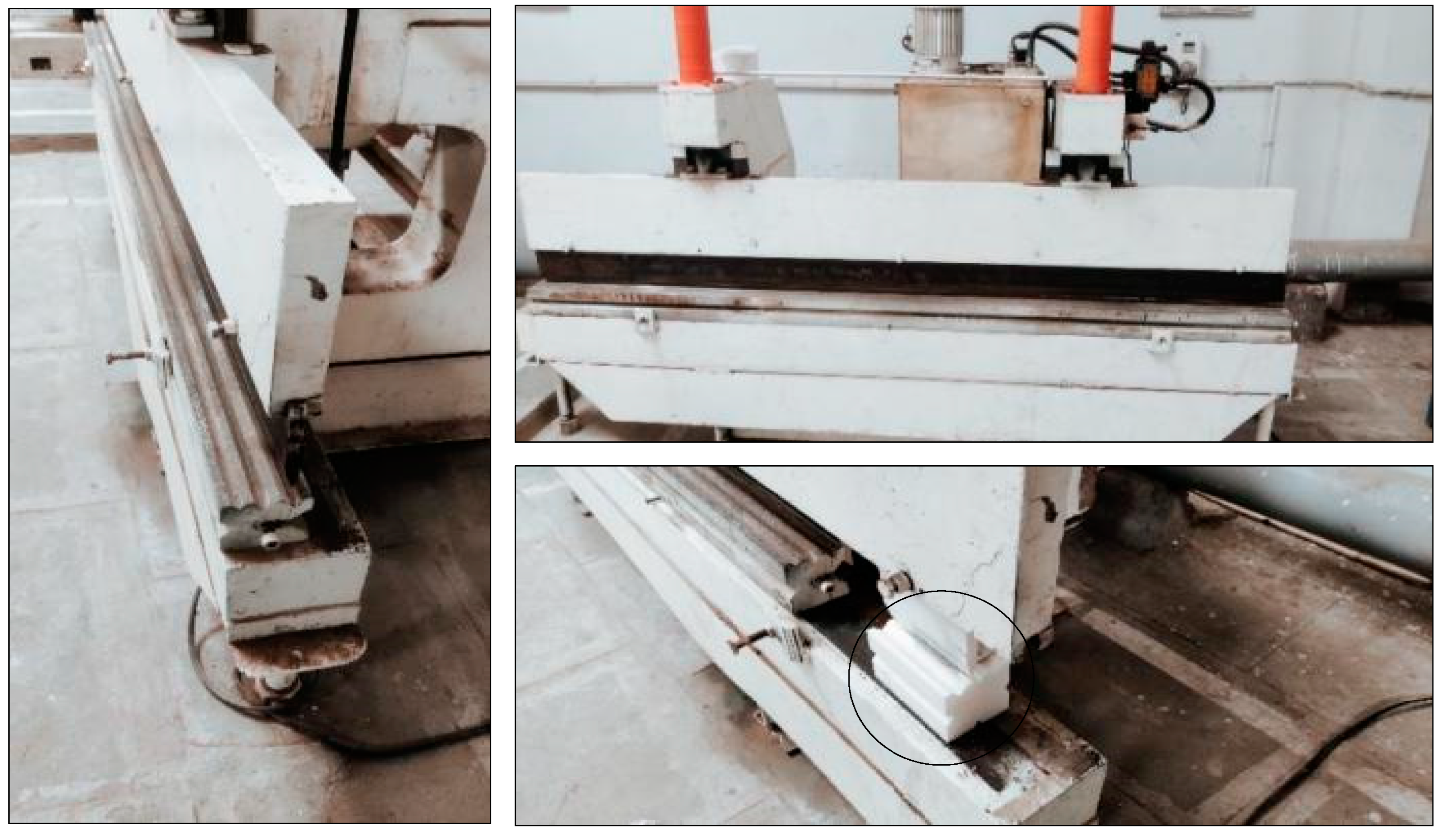
Figure 7.
Shows the tooling setup for V-bending operation.
4.2. V Bending of Samples by 3D Printed Tools
A hydraulic press machine with a 20 kN capacity is used for V-bending operations, employing standard dies and punches. The die and punch designs for 3D printing are customized to meet the machine’s specifications and availability. The tooling configuration for V-bending operations is illustrated in Fig. 7. For sample dimension die geometry and effective sheet metal usage, approximately twenty samples are produced for each angle. The loading conditions for aluminium grades range from 4 kN to 6 kN, while for steel grades, they range from 5 kN to 10 kN [37].
Figure 8.
V bending samples of AA6061 and SS304 for 30°, 45°, and 60°.
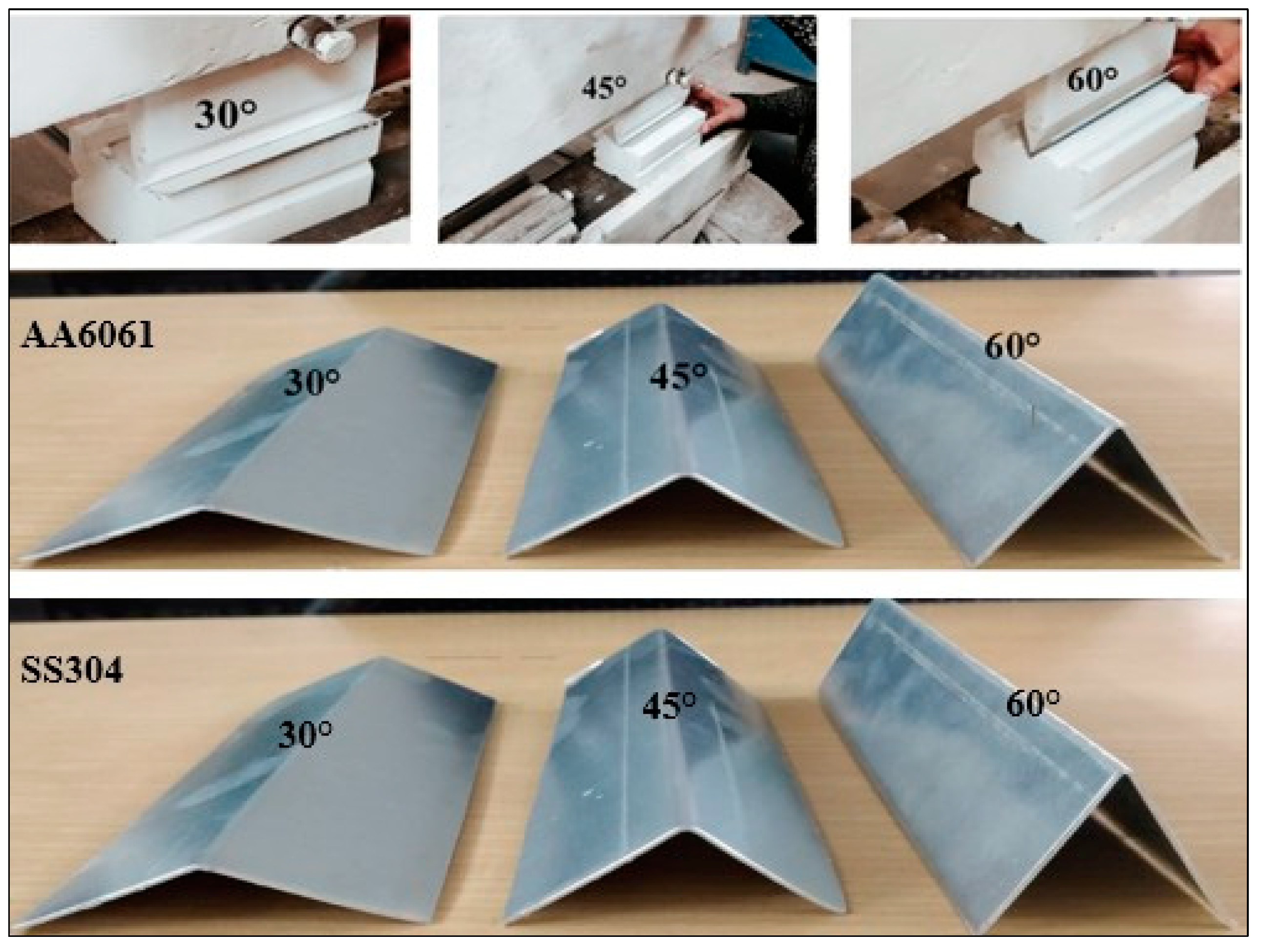
The samples are bent as shown in Fig. 8 in a V-shaped bending machine according to loading parameters to examine the formability and impact of the ABS die material on sheet bending. In terms of the bend sample’s profile, height, and thickness, the bending samples of both grades are validated and contrasted with the findings of the FEA. Errors including springback, tears, and cracking are checked in samples. For die and punch, the surface wear is additionally confirmed.
Figure 9.
Batch of samples bent for 30°, 45°, and 60°.
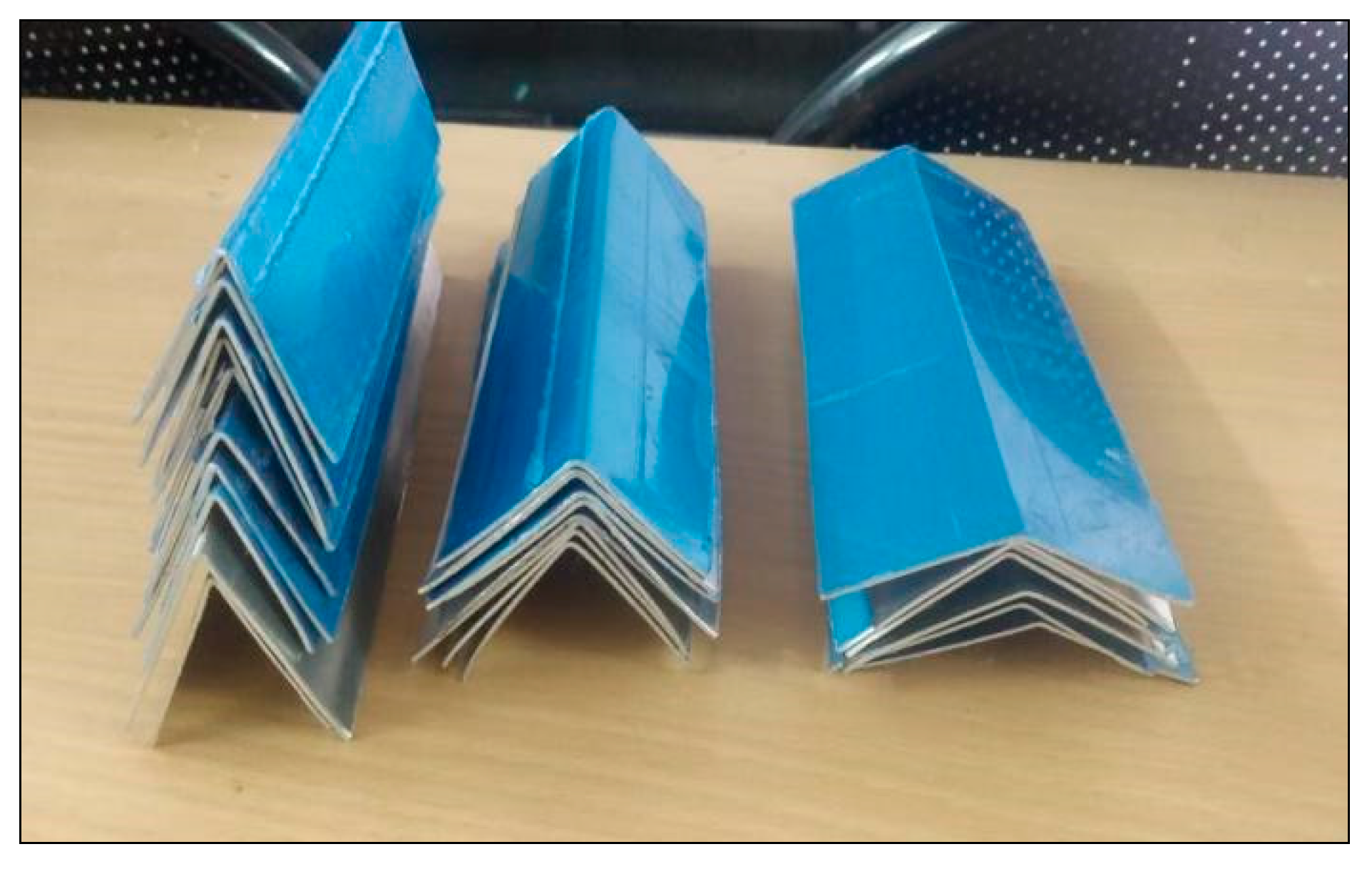
Table 5 shows that the average lengths of bend angles for both materials deviate negligibly from the theoretical and FEA results by only 0.007% and the bending angle deviation is on the lower side around 0.01% the bending angle as shown in Table 6 is higher in steel material compared to aluminium grade This minimal deviation indicates high accuracy and formability of the profile. The measurements confirm the precision and reliability of the bending process. The validation of the FEA results was carried out by comparing simulated geometries with experimental measurements obtained using a Vernier calliper (accuracy: ±0.02 mm) and a bevel protractor (accuracy: ±0.5°). The simulated and experimental data showed strong agreement, with deviations in bending length and angle being less than 0.01% and 0.02%, respectively. These minimal deviations confirm the reliability of the simulation model in predicting bending outcomes.
The error margins primarily stem from experimental variability, including minor tool wear and measurement inaccuracies, which were carefully controlled during the study. This quantitative comparison demonstrates the robustness of the FEA model and supports the practical applicability of the findings.
The failure modes observed in experimental samples, including tears and cracking, were analyzed, and correlated with high-stress regions identified in the FEA simulations. This comparison confirms the ability of the simulation model to predict areas prone to material failure.
Additionally, the actual bending angles were measured post-operation using a bevel protractor and compared with the intended and simulated angles. The results, as presented in Table 6, indicate a negligible deviation of less than 0.02% between the experimental and simulated angles, demonstrating the accuracy of the FEA model. Punch forces used during the experiments were also consistent with simulated values, further validating the reliability of the simulations.
Batch samples for angles of Sheet metal product manufacturing gain flexibility in terms of reworks, complex profiles, and cost-efficiency. Additive manufacturing provides significant economic advantages, particularly for batch production of various angles, compared to traditional manufacturing processes. The cost of tool production is reduced by fifty percent when using additive manufacturing tools. Table 7 compares the manufacturing costs of tools made from ABS grade and steel. 30°, 45°, and 60° for the aluminium grade are illustrated in Fig. 9.
5. Conclusions
Based on the research study, the following major conclusions can be drawn:
- Formability Testing with ABS Material: The formability of SS304 and AA6061 sheet metal was tested using ABS material. Simulations with this tool material were completed, and the bend samples exhibited a thinning within acceptable limits of 5%. The dimensional confirmability and formability of the samples were assessed using the Forming Limit Curve (FLC) in the initial stage.
- Wear Analysis of Die and Punch: The die and punch showed minimal signs of wear, with few skid marks on their surfaces. The principal stresses experienced during V-bending operations indicate that the tool material can withstand compressive loads up to 139 MPa, which is within permissible limits. This suggests that plastic materials can be effectively used for batch production.
- Samples bent using the ABS tooling were confirmed, and results were compared with FEA predictions. The results demonstrate that ABS materials are both adaptable and cost-effective for batch production. Wear analysis was qualitatively observed to be minimal based on visual inspection during the experimental trials. However, it should be noted that wear may increase when handling larger batches of more than 100 samples.
The study's results demonstrate that certain characteristics of AM-produced tools, especially those fabricated from ABS material, improve formability during the V-bending process. The customizable characteristics of additive manufacturing enable fine regulation of tool shape, thereby mitigating prevalent faults like springback and thinning by providing enhanced support to the sheet during the bending process. Secondly, the material qualities of ABS, such as its flexibility and shock-absorbing capabilities, contribute to the preservation of dimensional accuracy while alleviating stress concentrations at the bending junctures. These qualities enable a progressive dispersion of pressures throughout the sheet, thereby reducing surface damage and enhancing formability. Ultimately, AM's capacity to swiftly manufacture specialized, lightweight tools facilitates prompt modifications in tool design, accommodating small-batch and customized production needs without the significant expenses linked to conventional tooling materials.
Future Research Scope:
The combination of FEA simulations and plastic materials for tooling offers significant potential for future research and applications. This approach can be extended to evaluate the formability of advanced manufacturing processes such as deep drawing, stamping, extrusion, and other complex-forming methods. In addition, springback behaviour will be analysed. In-depth studies are required to employ quantitative methods, such as optical analysis or weight measurement, to provide a more comprehensive evaluation of tool wear.
Further studies can explore its applicability in analyzing complex product geometries with varying material grades and thicknesses. Additionally, the scalability of this methodology to larger and more intricate forming operations, as well as its performance in long-term and high-volume production scenarios, warrants further investigation. Moreover, the AM fabrication parameters such as orientation, layer thickness, etc. can be further explored.
Advancements in additive manufacturing materials such as ABS and its techniques could enhance the durability and performance of plastic tools, enabling their use in more demanding industrial applications.
Author Contributions
Conceptualization: Chandrakant V Bhatia and Dhiren Patel; Methodology: Chandrakant V Bhatia and Dhiren Patel; Formal analysis and investigation: Chandrakant V Bhatia; Writing original draft preparation: Chandrakant V Bhatia; Writing review and editing: Mustufa Haider Abidi and Fahad Alasim; Resources: Mustufa Haider Abidi and Fahad Alasim; Supervision: Dhiren Patel. All authors read and agreed upon the final version of the manuscript.
Funding
The authors would like to thank the Research Institute Supporting Program (RICSP-25-2), King Saud University, Riyadh, Saudi Arabia for funding this work. The authors give assurance for no ethical issues; the study is performed as per norms and standards.
Data Availability Statement
The original contributions presented in this study are included in the article/supplementary material. Further inquiries can be directed to the corresponding author(s).
Acknowledgements
The authors would like to thank Indus University and King Saud University for providing the necessary facilities and resources to conduct the research.
Conflicts of Interest
The author(s) declare(s) no conflicts of interest to report regarding the present study.
Ethics Approval
Not applicable.
References
- J. Pilthammar et al., “An overview of Methods for Simulating Sheet Metal Forming with Elastic Dies,” IOP Conf. Ser. Mater. Sci. Eng., vol. 1284, no. 1, p. 012054, 2023. [CrossRef]
- A. I. M. Greer et al., “Large volume nanoscale 3D printing: Nano-3DP,” Appl. Mater. Today, vol. 21, 2020. [CrossRef]
- D. Gu, “Chinese Journal of Mechanical Engineering : Additive Manufacturing Frontiers Additive Manufacturing towards Even Higher Performance,” Chinese J. Mech. Eng. Addit. Manuf. Front., vol. 2, no. 1, p. 100070, 2023. [CrossRef]
- T. Kermavnar, A. T. Kermavnar, A. Shannon, and L. W. O’Sullivan, “The application of additive manufacturing / 3D printing in ergonomic aspects of product design: A systematic review,” Appl. Ergon., vol. 97, no. July, 2021. [CrossRef]
- P. Kumar, S. K. P. Kumar, S. K. Sharma, and R. K. R. Singh, “Recent trends and future outlooks in manufacturing methods and applications of FGM: a comprehensive review,” Mater. Manuf. Process., vol. 38, no. 9, pp. 1033–1067, Jul. 2023. [CrossRef]
- M. C. P. Vila Pouca et al., “Simulating 3D printing on hydrogel inks: A finite element framework for predicting mechanical properties and scaffold deformation,” Finite Elem. Anal. Des., vol. 230, no. 23, 2024. 20 November. [CrossRef]
- U. Hofmann et al., “Design of an additively manufactured hydraulic directional spool valve: an industrial case study,” Virtual Phys. Prototyp., vol. 18, no. 1, 2023. [CrossRef]
- J. D. Kechagias, N. A. J. D. Kechagias, N. A. Fountas, K. Ninikas, M. Petousis, N. Vidakis, and N. Vaxevanidis, “Surface characteristics investigation of 3D-printed PET-G plates during CO2 laser cutting,” Mater. Manuf. Process., vol. 37, no. 11, pp. 1347–1357, Aug. 2022. [CrossRef]
- V. Mohanavel, K. S. V. Mohanavel, K. S. Ashraff Ali, K. Ranganathan, J. Allen Jeffrey, M. M. Ravikumar, and S. Rajkumar, “The roles and applications of additive manufacturing in the aerospace and automobile sector,” Mater. Today Proc., no. xxxx, 2021. [CrossRef]
- L. Bergonzi, A. L. Bergonzi, A. Pirondi, F. Moroni, M. Frascio, and M. Avalle, “A study on additive manufacturing build parameters as bonded joint design factors,” J. Adhes., vol. 00, no. 00, pp. 1–30, 2021. [CrossRef]
- M. I. M. Sargini, S. H. M. I. M. Sargini, S. H. Masood, S. Palanisamy, E. Jayamani, and A. Kapoor, “Additive manufacturing of an automotive brake pedal by metal fused deposition modelling,” Mater. Today Proc., vol. 45, pp. 4601–4605, 2021. [CrossRef]
- M. Shah, D. R. M. Shah, D. R.Patel, and S. Pande, “Additive manufacturing integrated Casting- A review,” Mater. Today Proc., vol. 62, pp. 7199–7203, 2022. [CrossRef]
- J. Pujante, B. J. Pujante, B. González, and E. Garcia-Llamas, “Pilot demonstration of hot sheet metal forming using 3D printed dies,” Materials (Basel)., vol. 14, no. 19, 2021. [CrossRef]
- N. Naveed, “Investigate the effects of process parameters on material properties and microstructural changes of 3D-printed specimens using fused deposition modelling (FDM),” Mater. Technol., vol. 36, no. 5, pp. 317–330, 2021. [CrossRef]
- L. Giorleo and E. Ceretti, “Aluminium deep drawing with additive manufacturing polymer punches: analysis of performance in small batch production,” Int. J. Adv. Manuf. Technol., vol. 128, no. 5–6, pp. 2175–2185, 2023. [CrossRef]
- G. Schuh, G. G. Schuh, G. Bergweiler, P. Bickendorf, F. Fiedler, and C. Colag, “Sheet metal forming using additively manufactured polymer tools,” Procedia CIRP, vol. 93, pp. 20–25, 2020. [CrossRef]
- N. Nakamura, K. N. Nakamura, K. ichiro Mori, F. Abe, and Y. Abe, “Bending of sheet metals using plastic tools made with 3D printer,” Procedia Manuf., vol. 15, pp. 737–742, 2018. [CrossRef]
- D. Klimyuk, M. D. Klimyuk, M. Serezhkin, and A. Plokhikh, “Application of 3D printing in sheet metal forming,” Mater. Today Proc., vol. 38, no. xxxx, pp. 1579–1583, 2021. [CrossRef]
- A. L. Bachmann, M. D. A. L. Bachmann, M. D. Dickey, and N. Lazarus, “Making light work of metal bending: Laser forming in rapid prototyping,” Quantum Beam Sci., vol. 4, no. 4, pp. 14–17, 2020. [CrossRef]
- E. Tekkaya, “Metal Forming,” Springer Handbooks, pp. 357–408, 2021. [CrossRef]
- G. Dengiz and K. Yildizli, “Experimental and simulated comparison of finite element models of bimetallic sheets for deep drawing process,” Int. J. Adv. Manuf. Technol., vol. 117, no. 11, pp. 3599–3614, 2021. [CrossRef]
- Taşkın and C., G. Dengiz, “Experimental and numerical optimization of deep drawing process parameters for square medical container design with the Taguchi method,” Int. J. Adv. Manuf. Technol., vol. 132, no. 5–6, pp. 2643–2659, 2024. [CrossRef]
- V. G. Zaragoza, K. V. G. Zaragoza, K. Rane, M. Strano, and M. Monno, “Manufacturing and performance of 3D printed plastic tools for air bending applications,” J. Manuf. Process., vol. 66, no. 20, pp. 460–469, 2021. 20 November. [CrossRef]
- L. Sattar Ullah, Xiaoqiang Li, “Fast simulation of incremental sheet metal forming by multi-tooling,” J. Manuf. Process., vol. 84, pp. 669–680, 2022. [CrossRef]
- S. Choudhari and S. S. Khasbage, “Experimental investigation of forming parameters for square cup deep drawing process,” Mater. Today Proc., vol. 44, no. xxxx, pp. 4261–4267, 2020. [CrossRef]
- Tondini, U. Arinbjarnar, A. Basso, and C. V. Nielsen, “3D printing to facilitate flexible sheet metal forming production,” Procedia CIRP, vol. 103, pp. 91–96, 2021. [CrossRef]
- A. Qadeer, G. A. Qadeer, G. Hussain, M. Alkahtani, and J. Buhl, “Springback behavior of a metal/polymer laminate in incremental sheet forming: stress/strain relaxation perspective,” J. Mater. Res. Technol., vol. 23, pp. 1725–1737, 2023. [CrossRef]
- V. G. Zaragoza, M. V. G. Zaragoza, M. Strano, L. Iorio, and M. Monno, “Sheet metal bending with flexible tools,” Procedia Manuf., vol. 29, pp. 232–239, 2019. [CrossRef]
- P. Khunt, M. A. P. Khunt, M. A. Makhesana, B. K. Mawandiya, and K. M. Patel, “Investigations on the influence of printing parameters during processing of biocompatible polymer in Fused Deposition Modelling (FDM),” Adv. Mater. Process. Technol., vol. 00, no. 00, pp. 1–17, 2021. [CrossRef]
- M. Geueke, P. M. Geueke, P. Frohn-SOrensen, J. Reuter, N. Padavu, T. Reinicke, and B. Engel, “Structural optimization of additively manufactured polymer tools for flexible sheet metal forming,” Procedia CIRP, vol. 104, no. March, pp. 1345–1350, 2021. [CrossRef]
- T.-T. Luyen, V.-C. T.-T. Luyen, V.-C. Tong, and D.-T. Nguyen, “A simulation and experimental study on the deep drawing process of SPCC sheet using the graphical method,” Alexandria Eng. J., 2021. [CrossRef]
- V. Bhatia and D. R. Patel, “A Review on Design of Additively Manufactured 3D Printed Tools for Sheet Metal Forming Processes,” ECS Trans., vol. 107, no. 1, pp. 13745–13755, 2022. [CrossRef]
- T. Aizawa, Y. T. Aizawa, Y. Suzuki, T. Yoshino, and T. Shiratori, “Fabrication of Punch and Die Using Plasma-Assisted 3D Printing Technology for Piercing Sheet Metals,” J. Manuf. Mater. Process., vol. 6, no. 3, 2022. [CrossRef]
- T. Sathish, M. D. T. Sathish, M. D. Vijayakumar, and A. Krishnan Ayyangar, “Design and Fabrication of Industrial Components Using 3D Printing,” Mater. Today Proc., vol. 5, no. 6, pp. 14489–14498, 2018. [CrossRef]
- Z. Cheng et al., “Forming limit analysis of AA5052 sheet under bilinear strain path by designing a novel large-scale gripping fixture,” J. Mater. Res. Technol., vol. 22, pp. 2425–2439, 2023. [CrossRef]
- P. Guo et al., “Development of strong, stiff and lightweight compression-resistant mechanical metamaterials by refilling tetrahedral wireframes,” Virtual Phys. Prototyp., vol. 19, no. 1, pp. 1–18, 2024. [CrossRef]
- M. Merklein, R. Schulte, and T. Papke, “An innovative process combination of additive manufacturing and sheet bulk metal forming for manufacturing a functional hybrid part,” J. Mater. Process. Technol., vol. 291, no. July 2020, p. 117032, 2021. [CrossRef]
Figure 1.
Overview of additive manufacturing techniques.
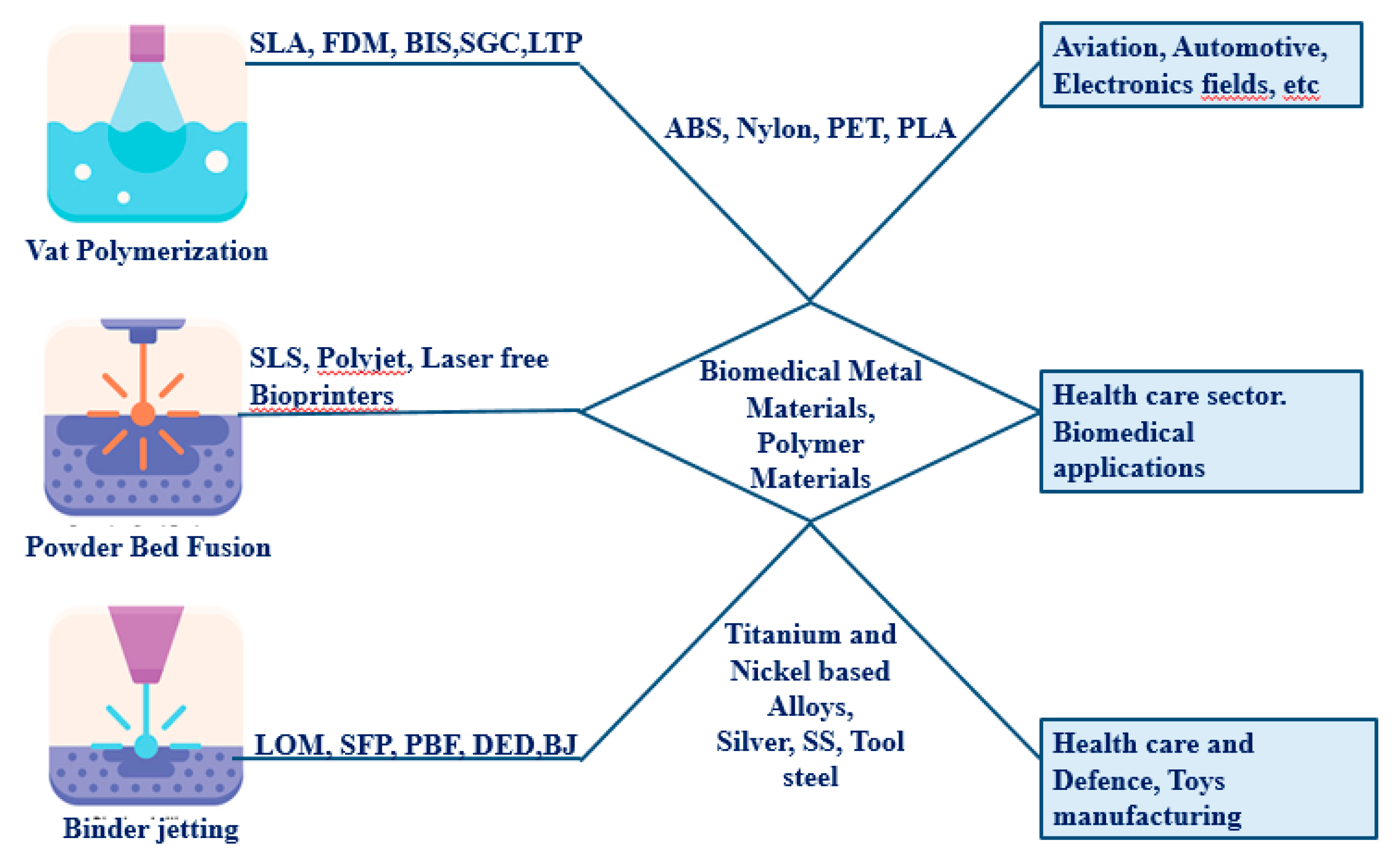
Figure 2.
Stress-strain diagram of AA6061 material.
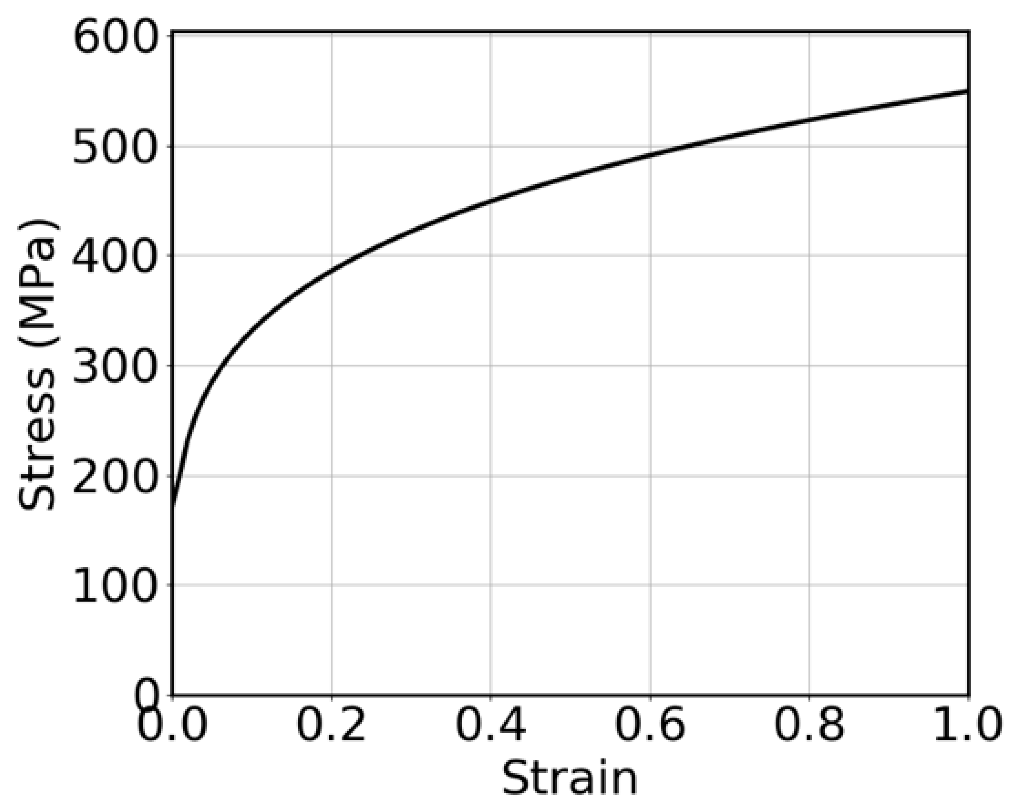

Table 1.
Input parameters for FEA simulation of V bending operation.
| Sr. no. | Input parameters | Characteristics | Values | |
| Steel | Aluminium Alloy | |||
| 1 | Material grade | Name | SS304 | AA6061 |
| 2 | Thickness (mm) | 1.0 | 1.0 | |
| 3 | Plastics Properties | Tensile stress (MPa) | 309.108 | 315.78 |
| 4 | R00 | 1.5 | 1.6 | |
| 5 | R45 | 1.5 | 1.6 | |
| 6 | R90 | 1.5 | 1.6 | |
| 7 | Elastics Properties | 7.8-e09 | 2.7-e09 | |
| 8 | Young’s modulus (MPa) | 210000 | 70000 | |
| 9 | Poisson’s ratio | 0.3 | 0.3 | |
| 10 | Yield strength (MPa) | 189 | 170.8 | |
Table 2.
Theoretical parameters of the V-bending operation.
| Material | Bending angle (degree) | Thickness (mm | K Factor | Radius(mm) | Bending Length (mm) (L1+L2-BA) | Punchforce (kN) |
| Steel Grade SS304 | 60 | 1 | 0.33 | 2 | 64 | 9.8 |
| 45 | 1 | 0.33 | 2 | 62 | 9.79 | |
| 30 | 1 | 0.33 | 2 | 60 | 9.7 | |
| Aluminum Grade 6061 | 60 | 1 | 0.33 | 2 | 64 | 5.5 |
| 45 | 1 | 0.33 | 2 | 62 | 5.48 | |
| 30 | 1 | 0.33 | 2 | 60 | 5.4 |
Table 3.
Summary of forming limit curve for V bending operations for SS304 and AA6061 material.
| Material | Bending Angles (°) | Forming limit curve |
| SS304 | 60 | 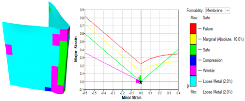 |
| 45 | 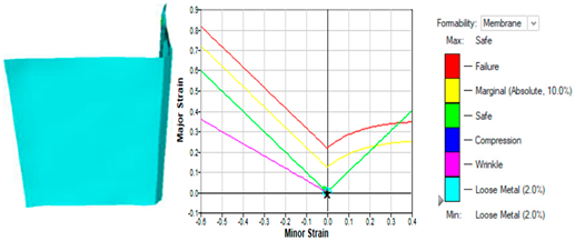 |
|
| 30 | 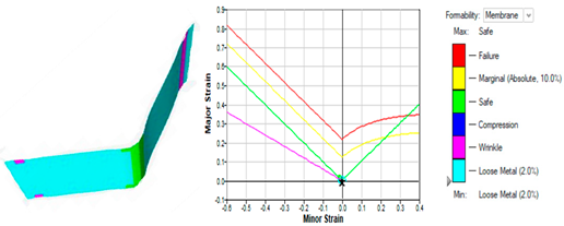 |
Table 4.
Chemical composition of AA6061 and SS304 grades.
| Sr. no. | AA6061 | SS304 | ||
| Elements | Percentage content | Elements | Percentage content | |
| 1 | Silicon | 0.577 | Carbon | 0.022 |
| 2 | Copper | 0.288 | Silicon | 0.329 |
| 3 | Zinc | 0.100 | Magnesium | 1.490 |
| 4 | Iron | 0.516 | Phosphorus | 0.019 |
| 5 | Magnesium | 0.870 | Sulphur | 0.007 |
| 6 | Manganese | 0.081 | Chromium | 18.730 |
| 7 | Chromium | 0.195 | Nickel | 8.160 |
| 8 | Titanium | 0.037 | - | - |
| 9 | Aluminium | 97.290 | Iron | 71.243 |
Table 5.
Bending Length of V bending samples for SS304 and AA6061.
| Material | Bending Angle (°) | Bending Length (mm) | Average (mm) | |||||||||
| Sample no | 1 | 2 | 3 | 4 | 5 | 6 | 7 | 8 | 9 | 10 | ||
| Steel SS304 | 60 | 64 | 63.9 | 63.8 | 64 | 63.9 | 64 | 63.98 | 63.97 | 64 | 63.95 | 63.95 |
| 45 | 61.98 | 62 | 62 | 61.98 | 62 | 61.97 | 61.5 | 62 | 61.97 | 62 | 61.3 | |
| 30 | 59.8 | 60 | 59.97 | 59.98 | 59.99 | 60 | 60 | 59.87 | 59.87 | 60.22 | 59.96 | |
| Aluminium 6061 | 60 | 64 | 63.6 | 63.2 | 64 | 63.8 | 63.9 | 63.98 | 63.97 | 64 | 63.98 | 63.84 |
| 45 | 61.99 | 62 | 62 | 61.9 | 62 | 61.99 | 62 | 62 | 61.97 | 62 | 61.97 | |
| 30 | 59.78 | 60 | 59.99 | 59.98 | 59.99 | 60 | 60 | 59.90 | 59.88 | 59.99 | 59.99 | |
Table 6.
Bending angle of V bending samples for SS304 and AA6061.
| Material | Bending Angle (°) | Bending Angle (°) for samples | Average(°) | |||||||||
| Steel SS304 | Sample no | 1 | 2 | 3 | 4 | 5 | 6 | 7 | 8 | 9 | 10 | |
| 60 | 62 | 61 | 62 | 63 | 61.5 | 60 | 61 | 60 | 61 | 60 | 61 | |
| 45 | 45 | 45.5 | 45 | 44.5 | 45 | 45 | 44.5 | 45 | 46 | 45 | 45.1 | |
| 30 | 31 | 31.5 | 30.5 | 30 | 30 | 30.5 | 30 | 31.5 | 30 | 31 | 30.6 | |
| Aluminium 6061 | 60 | 61.5 | 60 | 60 | 62 | 61 | 60 | 61 | 60 | 61 | 61.5 | 60.6 |
| 45 | 45 | 45 | 45.5 | 45 | 45 | 45.5 | 45 | 45.5 | 45 | 45 | 45 | |
| 30 | 30 | 30 | 31 | 31 | 31 | 30 | 30 | 30 | 30 | 30 | 30.2 | |
Table 7.
Cost comparison of steel and ABS tools.
| Specifications | Steel Grade | ABS Grade |
| Dimensions (mm) Die 150 × 90 × 90; V cut 150 × 45 ×45; Punch 150 × 120 ×15; V projection 150 × 120 ×15 | ||
| Volume | 1485× | 1485× |
| Density | 7.870 Kg/ | 1.05 Kg/ |
| Weight (kg) | 11.68 | 1.3 |
| Raw material cost ($) | 11.55 | 5.77 |
| Machining cost ($) | 0.92/kg= 10.80 | 5.77 |
| Surface polishing cost ($) | 2.89 | 0.58 |
| Total approximate Cost in ($) | 25.41 | 12.13 |
Disclaimer/Publisher’s Note: The statements, opinions and data contained in all publications are solely those of the individual author(s) and contributor(s) and not of MDPI and/or the editor(s). MDPI and/or the editor(s) disclaim responsibility for any injury to people or property resulting from any ideas, methods, instructions or products referred to in the content. |
© 2025 by the authors. Licensee MDPI, Basel, Switzerland. This article is an open access article distributed under the terms and conditions of the Creative Commons Attribution (CC BY) license (http://creativecommons.org/licenses/by/4.0/).
Copyright: This open access article is published under a Creative Commons CC BY 4.0 license, which permit the free download, distribution, and reuse, provided that the author and preprint are cited in any reuse.


