
Submitted:
05 June 2025
Posted:
12 June 2025
You are already at the latest version
Abstract
The Super-Twisting Sliding Mode Controller (STSMC) is considered one of the simplest and most practical nonlinear control systems, due to its ease of application in industrial systems. Its application helps minimize the chattering problem and significantly improves the durability of the system. However, this controller has several faults and concerns, as its use does not promote the expected improvement of systems. To overcome these shortcomings and optimize the efficiency and performance of this technique, a new method is suggested for the super twisting algorithm (STA). This study proposes and uses a new STA approach, named the fast super twisting algorithm (FSTA), applied to the traditional IFOC strategy to decrease the fluctuations of torque, current, and active power. The results from this suggested IFOC-FSTA method are compared with those of the traditional SMC and STA methods. The results obtained from this study demonstrate that the suggested method, which is based on FSTA, has outperformed the traditional method in terms of ripple ratio and response dynamics. This demonstrates the robustness of the proposed approach to optimize the generator performance and efficiency in the double-fed induction generator-based wind system.
Keywords:
Doubly fed induction generator
; Wind turbine
; Active and reactive power
; Super twisting algorithm STA
; Fast Super Twisting algorithm FSTA
; robust
1. Introduction
The integration of renewable energies continues to grow worldwide in the context of reducing pollutant emissions and greenhouse gases. However, their intermittent nature means that it is not possible to guarantee a continuous supply, which is why the exploitation of renewable energies is generally done by combining several sources, such as photovoltaic, wind, etc. Among renewable energies, wind power is currently the best placed in terms of economic profitability, it comes directly or indirectly from the energy generated by the wind. The operation of a 1 MW wind turbine makes it possible to avoid an annual release of around 2000 tonnes of carbon dioxide [1]
Nowadays, variable-speed wind systems based on the doubly fed induction generator (DFIG) are increasingly used in wind farms due to their robustness, simplicity of control, and suitability for variable wind speeds. When the DFIG is connected to the grid, it allows the converters to operate over a wide speed variation range of ±30% or less around the synchronization speed.
The double-fed induction generator (DFIG) is one of the most demanded generators in wind power conversion systems (WPCS) due to its efficiency and adaptable operation [3]. DFIGs are adopted for capturing wind energy since they keep rotor speeds constant regardless of wind speed. To ensure efficient energy transfer and guarantee grid stability, robust control of active and reactive power is required [4]. To have grid stability and efficient energy transfer, it is necessary to have more robust control of active and reactive stator powers.
Vector control, also referred to as indirect field-oriented control (IFOC), is an independent control method that is specifically used to regulate AC equipment. The latter offers better performance in transient and permanent regimes, even though it is effective in the face of parametric variations. On the other hand, its implementation is difficult, requiring very precise knowledge of the machine parameters.
Given the importance of wind energy production, studies have led to the design of robust controls making the system insensitive to external disturbances and parametric variations. It is the use of scientific methods and technical techniques to create strategies with greater performance and optimize the quality of energy in the electrical network.
In [5], the author has modified the control, replacing the PI controller with a sliding mode controller. The use of sliding mode control led to a significant improvement in the characteristics of the control strategy, as the response time became small and the ripple capabilities became small compared to the classical control strategy. In [6], another intelligent technique was used to optimize the control performance. Using fuzzy control as an intelligent method was used to decrease capacity fluctuations and improve the quality of the energy generated by the DFIG. Results from simulations demonstrate how well fuzzy control works to increase the benefits of the control. Some scientists have proposed to replace nonlinear techniques in order to optimize the performance of the control strategy. The PI controller is substituted by nonlinear methods to minimize the power fluctuations and obtain a method that is not influenced by the change of the parameters of the analyzed system.
This work is a development of the works [7], where the new method of the Fast Super Twisting Algorithm (FSTA) is used in place of the STA controller of the traditional control strategy. Moreover, the designed indirect FSTA strategy in this work is compared with the STA Super Twisting Algorithm in terms of electrical power, power ripple value, and response time. Accordingly, the contribution of the paper lies in introducing a new idea for the FSTA controller to improve the quality of the power produced by DFIG.
Consequently, this work is organized as follows. The new nonlinear method based on the Fast Super Twisting Algorithm FSTA is first explained and presented with the main advantages of this designed strategy. The necessary information is then given about the designed method of control strategy to be used to control a DFIG. Then the wind turbine system is introduced. The DFIG and wind turbine are modeled respectively. Finally, the characteristic of the DFIG control strategy using Fast Super Twisting Algorithm FSTA controllers is analyzed and compared.
2. The Control Schema
In this section, first, we represent the theoretical structure of the super twisting sliding mode and also the fast super twisting control for the general dynamics of rigid systems.
Traditional Super-Twisting Algorithm Design
The effectiveness of traditional sliding mode control relies on its robustness against external uncertainties and disturbances, under the pretext that the latter are restricted in the system. Due to the interruption of control operations, the chattering problem occurs when the system path moves close to the sliding surface.
The super-twisting algorithm (STA) can lessen the chattering issue while maintaining the advantages of traditional SMC. Besides, for the degree system, classical SMC requires its order sliding variables. However, for the same system, the super twisting algorithm only requires its own order motion variables. In the field of concrete engineering, this algorithm saves costs due to the reduction of the number of sensors.
Several sectors such as electronics, control, and renewable energy have adopted this technique due to its longevity, easy installation, simplicity, and ability to easily adjust the response [7,8,9]. Furthermore, the following equations describe the STA control law [10]:
Where: is the sign um function
The trajectory can converge to the sliding surface under the following conditions [7,8]:
Where: ,, are the positive constants of super-twisting sliding mode controller.
The control law (1) includes two parts. A continuous function of the sliding variable describes the second portion, while the first part is a function of the sliding variable's discontinuous derivative [11].
Based on Eq. (1) and to simplify the understanding and working principle of the STA controller, Figure 1 is designed, where this figure represents a simplified image of the working principle of the STA controller.
Figure 2.
Traditional STA controller.
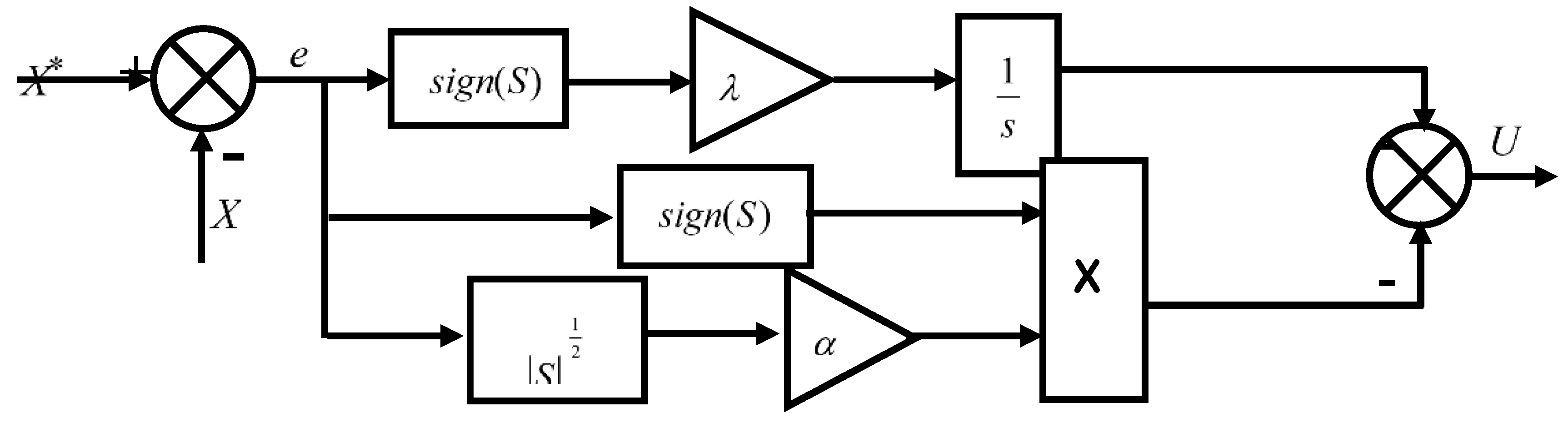
The use of this controller in automated systems such as the system for generating electric power from the wind does not eliminate the ripples, as there are ripples at the level of each of the active and reactive power. In addition, the quality of the current in the network is low, which causes disturbances in the operation of the equipment. Accordingly, another method called the Fast Super Twisting FSTA is introduced to STA to obtain a new, more robust nonlinear method and keep STA simple and easy [10].
2.2. Proposed FSTA Controller.
This work presents a new model of STA controller based on the fast technique to improve the performance and efficiency of the control strategy.
In traditional super twisting mode control, the sliding mode surface associated with the proportional term is determined by a square root. The gain of the proportional term directly influences the ability to track the disturbance. To optimize the convergence speed and robustness of the system, this paper proposes an FSTA based on the Fast Super Twisting (FSTA) [21]:
This study suggests an FSTA based on the fast terminal sliding mode to increase the system's robustness and convergence speed, specifically:
Where the control parameters,,, , ,are all greater than 0 .
2.2.1. Stability Analysis
Convergence conditions allow the system dynamics to converge towards the sliding surfaces. We retain two conditions from the literature. These correspond to the mode of convergence of the system state.
2.2.1.1. Direct Commutation Function
This is the first condition for convergence, proposed by [21]. It involves giving the surface dynamics that converge toward zero. It is expressed in the form:
In other words, we have:
2.2.1.2. Lyapunov Function
This involves formulating a positive scalar function ( ) for the system's state variables and choosing the switching law that will cause this function to decrease. The idea is to choose a scalar function to ensure the attraction of the variable to be controlled toward its reference value and to construct a control " " such that the square of the surface corresponds to a Lyapunov function. Defining the Lyapunov function as:
The derivative of this function is:
For the function to decrease, it is sufficient to ensure that its derivative is negative. This is only verified if condition (6) is satisfied. Equation 7 explains that the square of the distance to the surface measured decreases all the time, forcing the trajectory of the system to move towards the surface on both sides. This condition assumes an ideal sliding regime where the switching frequency is infinite [21].
Equation (3) indicates the application of the FSTA control law, which yields:
Equation (9) illustrates that when all of the FSTA approaching law's parameters, k1 and k2, are greater than 0, then The system will converge to the sliding surface because the controller developed using the FSTA law is asymptotically stable, according to the Lyapunov stability theorem.
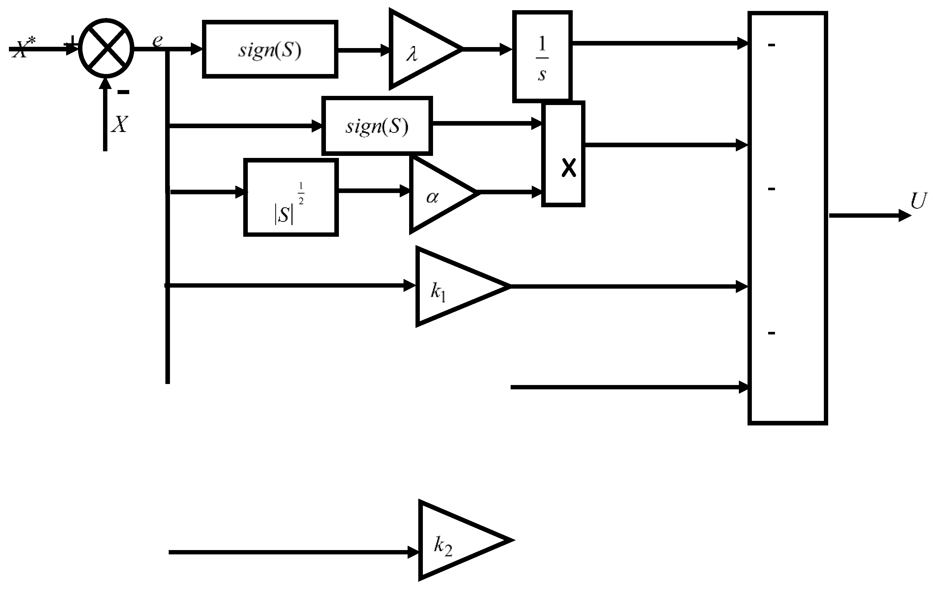
The FSTA controller is a modified version of the STA controller in order to improve its longevity.
The proposed FSTA controller is shown in Figure 2, the designed FSTA technique is simple, uncomplicated, easy to adjust, and can be implemented easily. Moreover, this proposed method can be easily applied to complex systems. In the next part, the designed nonlinear controller is applied to control the DFIG-based wind power [12,13].
Figure 2.
Proposed FSTA controller.
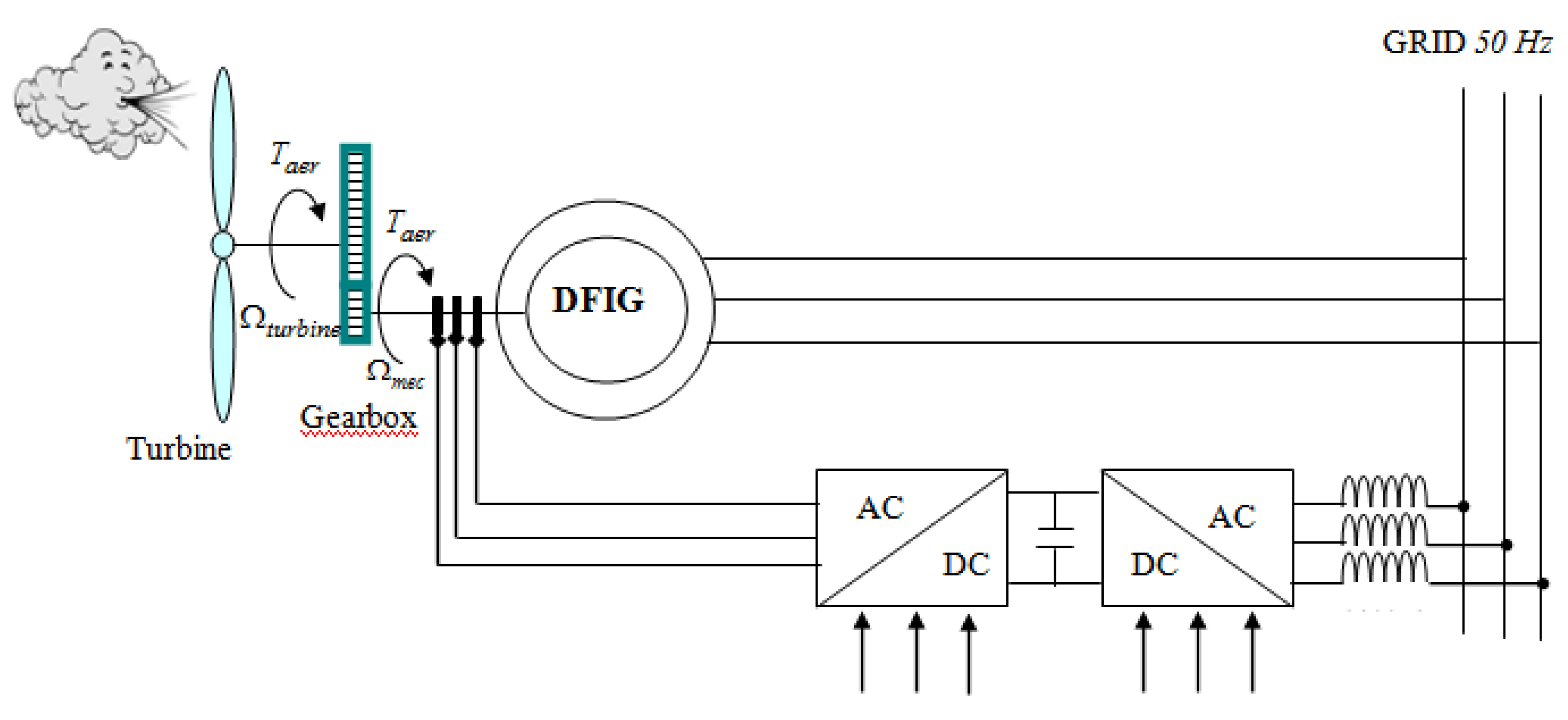
3. Modeling of the Wind Turbine and Gearbox
The power of the wind is given by:
The aerodynamic power appearing at the turbine rotor is expressed as follows:
Where: is the coefficient of aerodynamic power. It depends on the tip speed ratio and the orientation angle of the blades [15]
is defined as the ratio of the tip speed of the turbine blades to wind speed is given by the following expression:
Where : is the radius of the turbine, is angular speed of the turbine and is the wind speed.
The expression for is given by [16]:
The aerodynamic torque can be expressed as a function of the aerodynamic power and the speed of the turbine by:
4. Modeling of the Double Fed Induction Generator
A doubly-fed induction generator (DFIG) wind turbine is shown in Figure 3. Through distinct slip rings for each winding, the rotor is connected to a back-to-back power converter, while the stator is connected to the grid. The converter only needs to handle a fraction of the stator power (up to 30%) [14].
Figure 4.
Block diagram of a DFIG-based wind turbine.
The mathematical model of voltages for the DFIG stator and rotor in the Park reference frame is described by equations [17]:
Where, , ,are defined as stator and the rotor of dq-axis voltage.
and are the stator and rotor resistances.
,,, and are demonstrated as the stator and rotor of dq -axis flux. ω and ωr are the electrical speed and reference rotation speed
The active and reactive stator and rotor powers are given by:
The electromagnetic torque is given bys,
5. Control Strategy of the Double Fed Induction Generator
5.1. Decoupling of the Active and Reactive Powers
When the DFIG is connected to an existing network, this link requires a three-phase setup. The first phase involves matching the stator voltages to the network voltages, which serve as indicators. 2 The next step is to connect the stator to this network. Once this is completed, the link can actually be set up. Once this connection is achieved, the third step is the regulation of the transit of the power between the DFIG and the grid. To achieve high-performance control of the wind system, a stator flux field-oriented approach is usually used. So, by setting the quadratic component of the stator to the null value as follows [18]:
Then, the torque is simplified as indicated below:
By neglecting the stator resistance,
The following equations are obtained when replacing the rotor flux Eq. (21) in Eq. (16) and using the above condition Eq. (20), the rotor voltages are:
Where: is the slip frequency,is the slip range and is the leakage coefficient. The rotor voltages can be rewritten as follows [19]:
With and are the crosses coupling terms between the-axis and -axis:
The stator active and reactive power can then be expressed only versus these rotor currents as:
5.3. Super-Twisting Sliding Mode Control Design
The errors of the powers are given by:
Where and are the reference values of the statoractive and reactive powers.
Then we will have:
Substituting Eq. (28) into Eq. (26) leads to:
So the equivalent command is given by:
Therefore:
The equivalent command is is defined as:
Therefore:
5.4. Fast Super Twisting Algorithm Design
In this part, we will focus on the application of the fast super-twisting algorithm to the control of the active and reactive stator powers of the doubly-fed asynchronous generator (DFIG). The sliding surfaces are chosen in order to independently control the active and reactive generated powers.
and will be the two components of the control vector used to constraint the system to converge to The control vector is obtain by imposing , so the equivalent control components are given by the following relation : The super-twisting control can be described as:
Where:
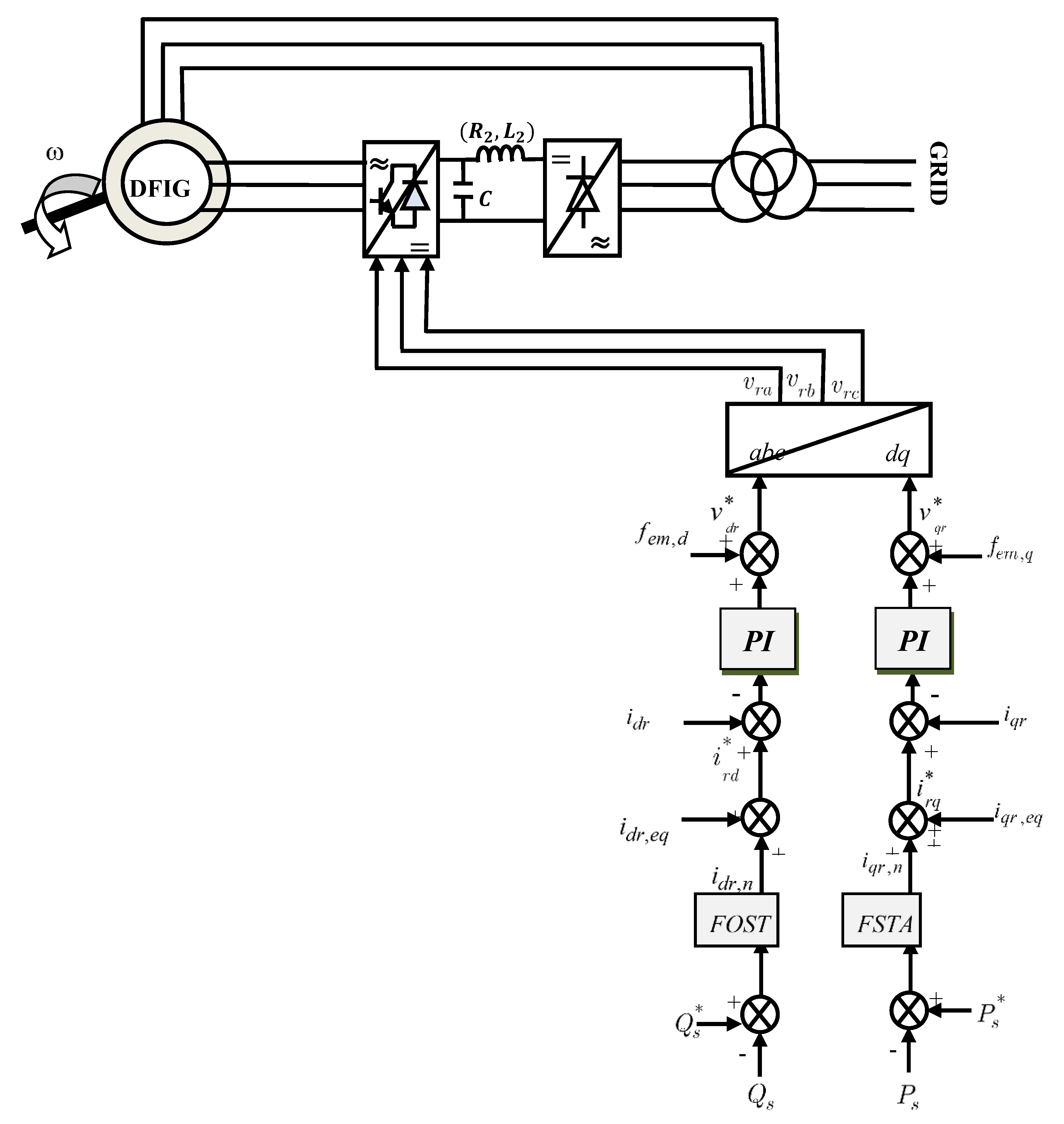
Figure 4 illustrates the scheme of the fast super-twisting algorithm (FSTA) applied to the control of active and reactive powers of the DFIG.
Figure 5.
Configuration of the power control of the DFIG with FSTA.
6. Results and Discussion
To test the performance of the proposed FSTA in wind turbine active/reactive power regulation; a comparative study is conducted under variable wind speed scenarios. Matlab/Simulink is used to create a simulation model for a 7.5 KW DFIG wind turbine. The parameter values of the DFIG used in this work are presented in the following table:

Table 1.
Parameters.
| Item | Symbol | Data |
|---|---|---|
| DFIG mechanical power | ||
| Pole pairs number | ||
| Stator resistance | ||
| Rotor resistance | ||
| Stator self inductance | ||
| Rotor self inductance | ||
| Mutual inductance | ||
| Gain of gearbox | ||
| Moment of inertia (DFIG+TURBINE) | ||
| friction coefficient (DFIG+TURBINE) | ||
| Nominal frequency |
6.1. First Test Reference Tracking
A comparison of the control effectiveness of the traditional SMC, STA, and FSTA control methods is done in order to demonstrate the usefulness of the FSTA speed control strategy. A PI controller with the same parameters is used in the current loop.
In the first test, the machine is driven at a fixed or variable speed while active and reactive power steps are applied. With the use of this test, we can confirm how well the measured powers hold steady when the machine's rotational speed suddenly changes.
The conversion system is shown schematically in Figure 5. The machine's stator side is directly connected to the grid. The rotor circuit is powered by an inverter controlled by the PWM technique.
The Indirect control strategy for active and reactive stator power was implemented in the Matlab/Simulink environment to evaluate and test the complete system for constant or variable speed operation.
Figure 6 displays the results of this test, which looks at reference following behavior for the conventional IFOC-SMC and IFOC-ST methods as well as the proposed IFOC-FST approach. This figure demonstrates how the torque, active power, and reactive power precisely match the references for every IFOC method. The recommended IFOC-FST approach has yielded superior results in terms of undulations for active, reactive power, and torque when compared to the conventional IFOC-SMC and IFOC-ST Methods (see Figure 7). The generated torque and active power share the same shape in Figure 6, demonstrating that an increase in active power is accompanied by an increase in torque. Additionally, the proposed IFOC-FST method reduced torque ripples in comparison to the classical method.
6.2. Robustness Against Wind Speed Variations
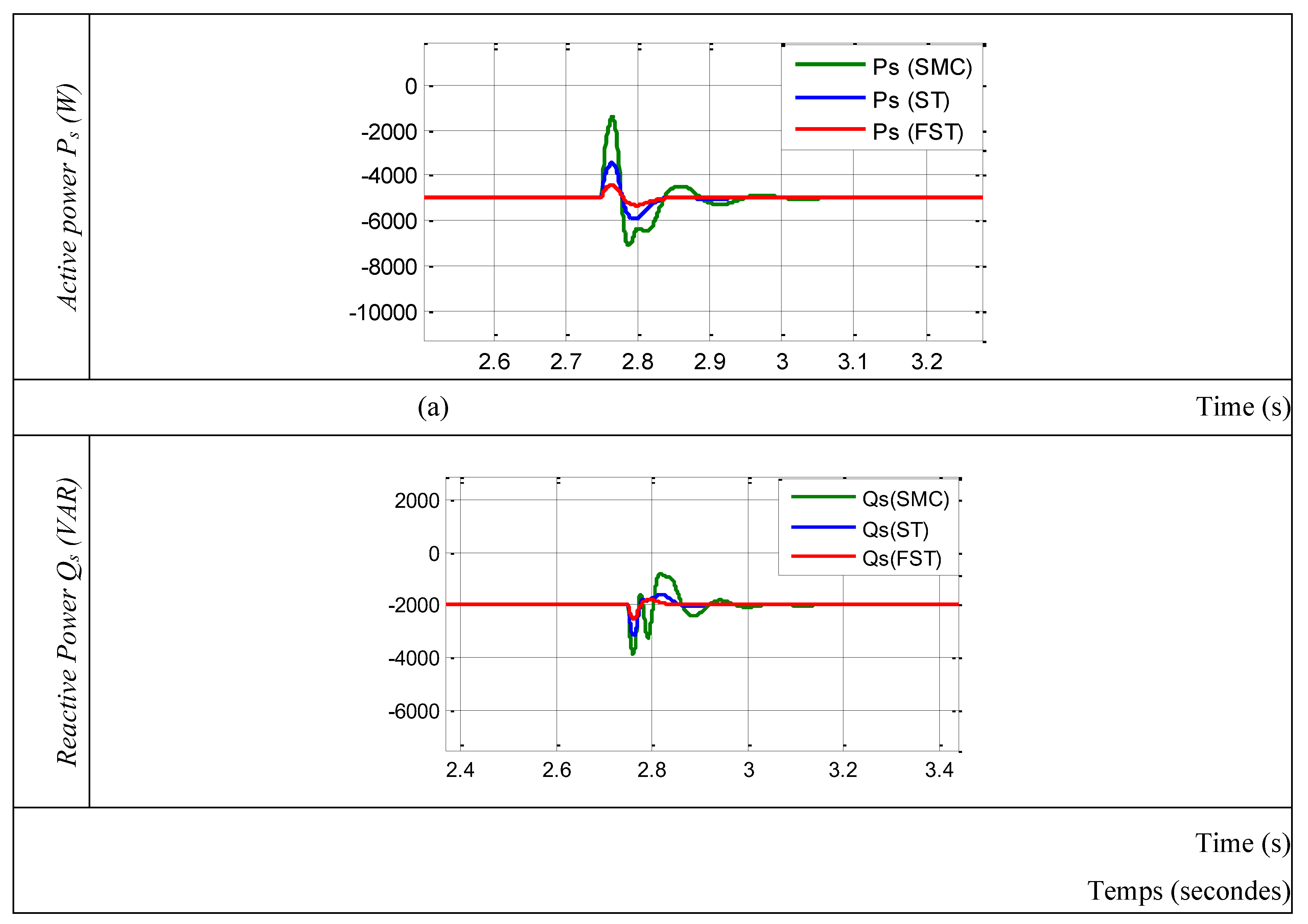
Maintaining the stability and effectiveness of DFIG-WES depends on avoiding torque oscillations during abrupt changes in wind speed and ensuring steady power injection into the electrical grid. The mechanical integrity of the wind turbine and grid stability may suffer from significant overshoots and power and torque fluctuations brought on by abrupt changes in wind speed. In order to minimize these effects and maximize energy extraction, the system must be able to react to changes in wind speed smoothly and consistently. In this study, the wind speed is stepped up from 12 m/s to 9 m/s for the DFIG. The corresponding output active and reactive power responses are displayed in Figure 8.
For a more in-depth comparative study, it would be interesting to compare the active and reactive power responses of the three controllers studied: SMC, ST and FST.
The active and reactive power responses for the three controllers SMC, ST, and FST with varying speeds are shown in Figure 8.
The curves obtained show, for the process to be controlled and equipped with the FST structure, better behavior in both tracking and regulation. We can observe a response without overshoot or oscillations. Disturbances due to speed changes have a negligible influence and are rejected immediately.
Table 2 and Table 3 reflect the three controller’s respective performances. Where ΔX represents the maximum difference between the reference power and the measured power (active and reactive), in the event of a disturbance being applied, while reject corresponds to the time required for the power to reach the corridor defined by the reference during the same test, and tr5% is the system response time.
Table 2.
Comparison of the performance of SMC, ST and FST active power regulator.
| Active Power Regulator | tr5% (ms) | ΔX (W) | trejet (ms) |
|---|---|---|---|
| SMC type | 122 | 270 | 81 |
| ST type | 75 | 180 | 50 |
| FST type | 009 | 005 | 009 |
Table 2.
Comparison of the performance of SMC, ST and FST reactive power regulator.
| Reactive Power Regulator | tr5% (ms) | ΔX (W) | trejet (ms) |
|---|---|---|---|
| SMC type | 88 | 270 | 70 |
| ST type | 70 | 200 | 50 |
| FST type | 002 | 007 | 007 |
6.3. Robustness Against Parameters Variations
In order to test the robustness of this Fast Super Twisting structure, we studied the influence of parametric variations on the power control performance. We consider variations on all parameters that can undergo changes (stator and rotor resistances, stator and rotor inductances). We introduce an increase from 1 to 1.8 of the nominal value on the resistances, and from 1 to 0.8 of the nominal value on the inductances. We represent the most important quantities which are the system output (active and reactive powers). The performances are evaluated through a numerical simulation under the same operating conditions presented in the previous sections.
Figure 9.
second test results. (a) Active power; (b) Reactive power.
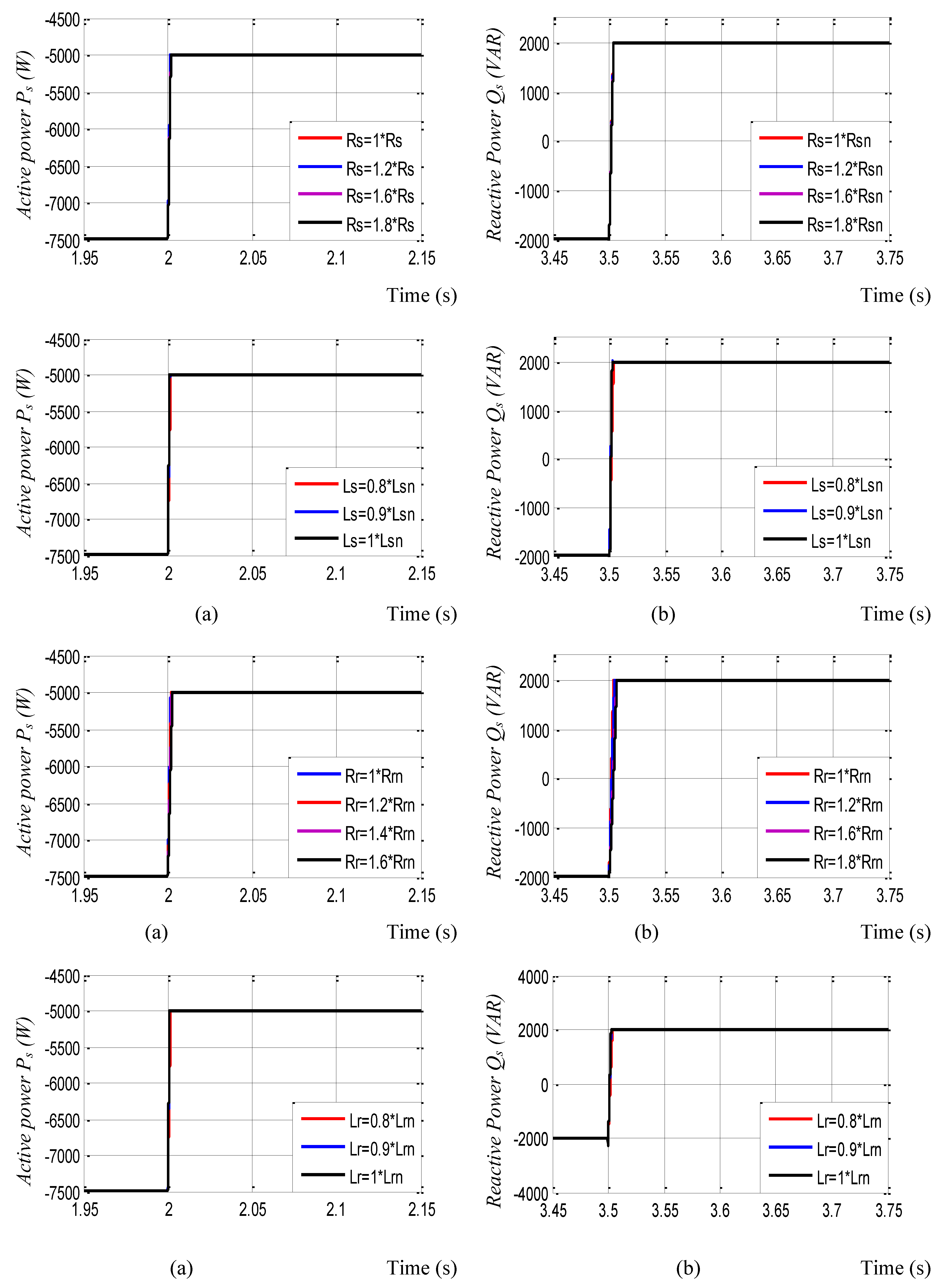
The results of the tests carried out show that the regulation of the active and reactive stator powers is always carried out and that only the variation of the rotor parameters slightly affects the response time of the system.
7. Conclusion
In this paper, we have presented a complete device for generating electricity using a Double Fed Induction generator based wind turbine. The system under study consists of a DFIG with a stator that is directly connected to the network and a rotor that is connected to the same network through two converters. (machine inverter and grid inverter). Machine control has been introduced to control the exchange of active and reactive power between the grid and the machine. Two different controllers are synthesized and compared. In term to regarding reference tracking, sensitivity to disturbances and parameter variations. The developed method has overcome the main disadvantages of Fast super twisting control (FSTA), such as the large fluctuations of reactive and active power caused by the switching frequency. Furthermore, the oscillations of both active and reactive power have been improved.
The dynamic qualities (torque, reactive, and active power) showed a significant improvement, according to the numerical data. Furthermore, the results obtained from this work are described in the following points:
- ➢
- The efficiency of the variable speed DFIG system is improved thanks to the Fast Super Twisting controller.
- ➢
- Compared to the Super Twisting Algorithm (STA), the Fast Super Twisting control (FSTA) is more robust. In comparison to the Super Twisting Algorithm (STA) and other approaches proposed in the literature, it lessens the variations of active power, torque, and reactive power.
In the context of future research, the Fast Super Twisting control (FSTA) method suggested in this paper will be tested on an asynchronous generator in a wind turbine system. This strategy can also be implemented on other generators, such as the asynchronous multiphase generator.
Nomenclature
| STA | Super Twisting Algorithm |
| FSTA | Fast Super Twisting Algorithm |
| IFOC | Indirect Field-Oriented Control |
| DFIG | Double Fed Induction Generator |
References
- Baggu, M.M.; Chowdhury, B.H.; Kimball, J.W. 2015. Comparison of advanced control techniques for grid side converter of doubly-fed induction generator back-to-back converters to improve power quality performance during unbalanced voltage dips. IEEE J. Emerg. Sel. Top. Power Electron. 3 (2), 516–524. [CrossRef]
- Chhipą, A.A.; Chakrabarti, P.; Bolshev, V.; Chakrabarti, T.; Samarin, G.; Vasilyev, A.N.; Ghosh, S.; Kudryavtsev, A. 2022. Modeling and control strategy of wind energy conversion system with grid-connected doubly-fed induction generator. Energies 15, 6694. [CrossRef]
- Gasmi, H.; Mendaci, S.; Laifa, S.; Kantas, W.; Benbouhenni, H. 2022. Fractional order proportional integral super-twisting sliding mode controller for windenergy conversion system equipped with doubly fed induction generator. J. Power Electron. 2022, 1–17. [CrossRef]
- Najib, E.; Aziz, D.; Abdelaziz, E.; Mohammed, T.; Youness, E.; Khalid, M.; Badre, B. 2019. Direct torque control of doubly fed induction motor using three-level NPC inverter. Prot. Control Mod. Power Syst. 4 (17), 1 9. [CrossRef]
- Kh, Belgacem, Sliding Mode Control of a Doubly-fed Induction Generator for Wind Energy Conversion, International Journal of Energy Engineering, Vol. 30 N°01,pp 30-36, 2013.
- Kh, Belgacem, Fuzzy Logic Control of Double-Fed Induction Generator Wind Turbine, International Review of modelling and simulation (IREMOS), Vol. 6 N°01, 2013.
- Houaria Abdelli Synthesis of SMC algorithms applied to wind generator International Journal of Power Electronics and Drive Systems (IJPEDS) Vol. 12, No. 1, Mar 2021, pp. 404~412. [CrossRef]
- Benbouhenni, H.; Bizon, N.; Colak, I.; Thounthong, P.; Takorabet, N. 2022b. Simplified super twisting sliding mode approaches of the double-powered induction generator-based multi-rotor wind turbine system. Sustainability 14. [CrossRef]
- Gasmi, H.; Mendaci, S.; Laifa, S.; Kantas, W.; Benbouhenni, H. 2022. Fractional order proportional integral super-twisting sliding mode controller for wind energy conversion system equipped with doubly fed induction generator. J. Power Electron. 2022, 1–17. [CrossRef]
- Arie Levant 2007. Principles of 2-sliding mode design. Automatica Volume 43, Issue 4, April 2007, Pages 576-586.
- González-Hernández, I.; Salazar, S.; Lozano, R.; Ramírez-Ayala, O. 2022. Realtime improvement of a trajectory-tracking control based on super-twisting algorithm for a quadrotor aircraft. Drones 6. [CrossRef]
- Maaruf, M.; Khalid, M. 2022. Global sliding-mode control with fractional-order terms for the robust optimal operation of a hybrid renewable microgrid with battery energy storage. Electronics 11. [CrossRef]
- Li, G.; Chen, B.; Chen, H.; Deng, W. 2022a. Fractional-order PIλdµ controller using adaptive neural fuzzy model for course control of under actuated ships. Appl. Sci. 12. [CrossRef]
- Alam, M.S.; Al-Ismail, F.S.; Abido, M.A. 2021. PV/Wind-Integrated low-inertia system frequency control: PSO-optimized fractional-order PI-based SMES approach. Sustainability 13. [CrossRef]
- Aouzellag, D.; Ghedamsi, K.; Berkouk, E.M. Modelling of doubly fed induction generator with variable speed wind for network power flow control, JTEA’06, Tunis.
- Sara, K.; Khoukha, I.; El Madjid, B.; Benbouhenni, H.; Emad, A. A direct vector control based on modified SMC theory to control the double-powered induction generator-based variable-speed contra-rotating wind turbine systems. Energy Rep. 2022. [Google Scholar] [CrossRef]
- Errouissi, R.; Al-Durra, A.; Muyeen, S.M.; Leng, S.; Blaabjerg, F. Offset-free direct power control of DFIG under continuous-time model predictive control. IEEE Trans. Power Electron. 32(3), 2265–2277 (2016).
- Echiheb, F.; Ihedrane, Y.; Bossoufi, B.; et al. 2022. Robust sliding-backstepping mode control of a wind system based on the DFIG generator. Sci. Rep. 12, 11782. [CrossRef]
- Ghennam, T.; Berkouk, E.M.; Francois, B. A vector hysteresis current control applied on three-level inverter. Application to the active and reactive power control of doubly fed induction generator based wind turbine, International Review of Electrical Engineering, Vol. 2(Issue 2): 250 – 259, March 2007.
- Zhe song; Weihong Zhou, PMSM Disturbance Resistant Adaptive Fast Super-Twisting Algorithm Speed Control Method IEEE Acess Volume 12, 2024.
- Utkin, V.I. Variable structure systems with sliding modes, IEEE Trans. On Aut. Cont.; Vol. AC–22, pp. 212–222, 1977.
Figure 6.
First test results. (a) Active power; (b) Reactive power; (c) Torque.
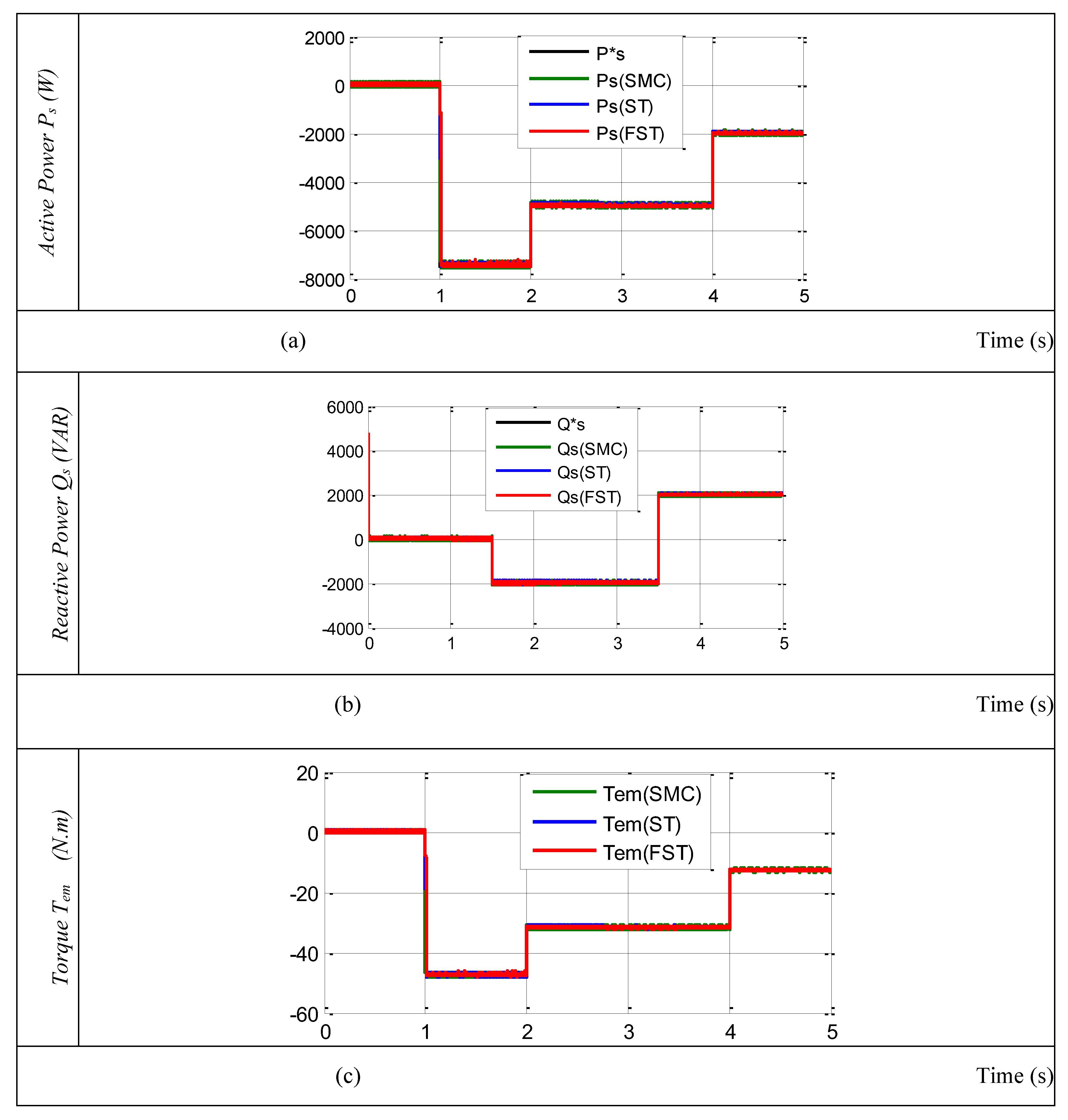
Figure 7.
Zoom in the first test results. (a) Active power; (b) Reactive power; (c) Torque.
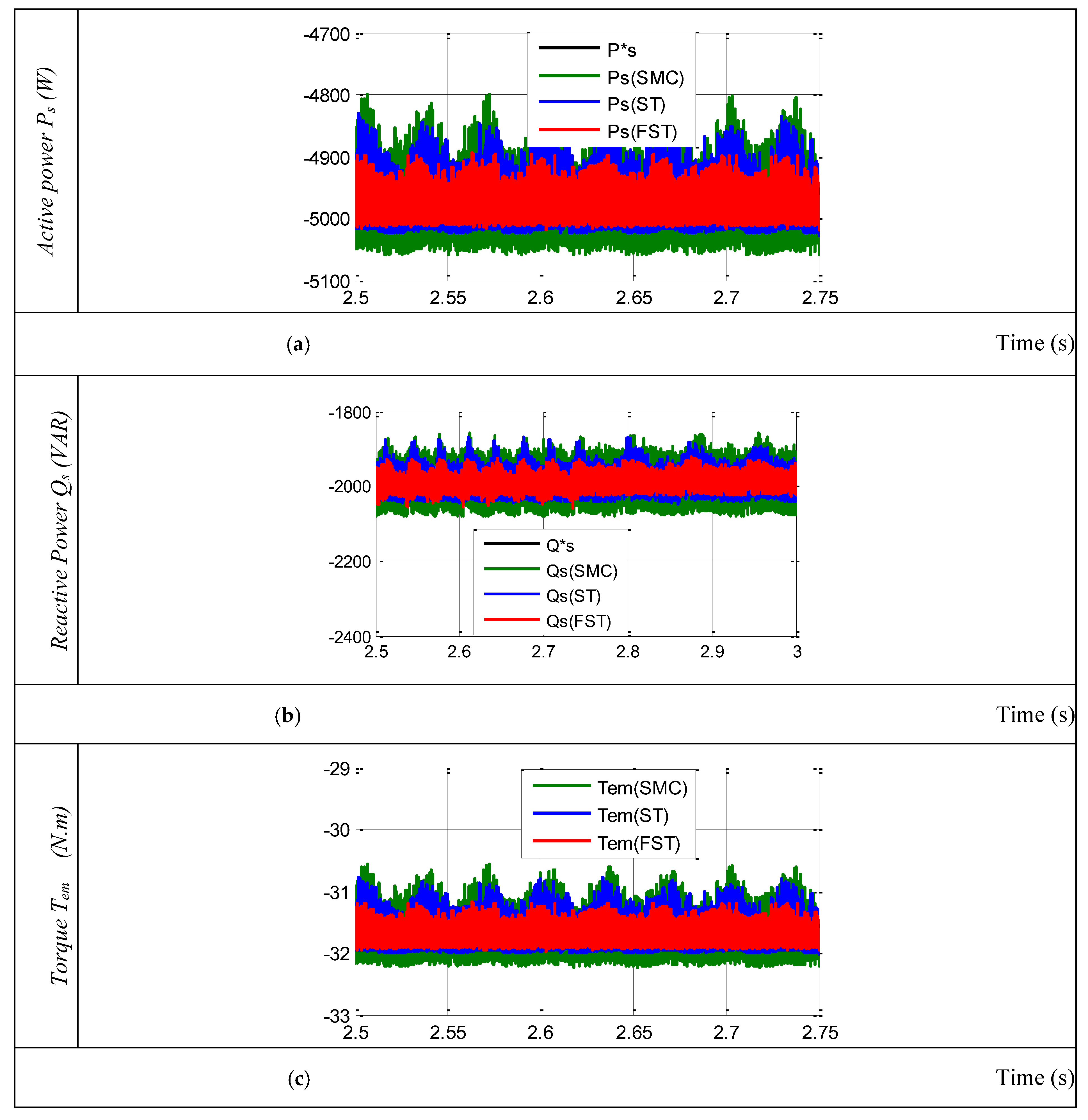
Figure 8.
First test results. (a) Active power; (b) Reactive power; (c) Torque..
Disclaimer/Publisher’s Note: The statements, opinions and data contained in all publications are solely those of the individual author(s) and contributor(s) and not of MDPI and/or the editor(s). MDPI and/or the editor(s) disclaim responsibility for any injury to people or property resulting from any ideas, methods, instructions or products referred to in the content. |
© 2025 by the authors. Licensee MDPI, Basel, Switzerland. This article is an open access article distributed under the terms and conditions of the Creative Commons Attribution (CC BY) license (http://creativecommons.org/licenses/by/4.0/).
Copyright: This open access article is published under a Creative Commons CC BY 4.0 license, which permit the free download, distribution, and reuse, provided that the author and preprint are cited in any reuse.


