Submitted:
17 December 2024
Posted:
18 December 2024
You are already at the latest version
Abstract
The sub-synchronous oscillation accident of large-scale doubly fed wind turbines connected to a grid through series compensation has caused a serious impact on the power system. By optimizing the parameters of the doubly fed fan control system, the system impedance can be effectively improved to solve the problem of sub-synchronous oscillation. However, owing to the complexity of a grid-connected system of doubly fed fans and the influence of the time-varying oscillation characteristics of the system, it is often difficult to achieve a successful suppression. To solve this problem, this paper proposes an optimized additional damping method for the rotor and grid-side controllers, which can achieve efficient suppression of sub-synchronous oscillation. The parameters of the proposed additional damping method are optimized for all variable operation conditions using a genetic algorithm under the established frequency-domain impedance model. The detailed time-domain simulation model was constructed with the RTLAB platform to verify the proposed method. The experimental results show that the optimized control strategy can effectively and quickly suppress the sub-synchronous oscillation under different working conditions, and the amplitude suppression rate reached 85.99%, which effectively improved the grid-connected stability of wind turbines.
Keywords:
Additional damping controller
; Doubly-fed induction generator
; Series capacitance compensation
; Sub-synchronous oscillation
1. Introduction
By the end of 2022, the cumulative installed photovoltaic capacity and wind power capacity in the world are approximately 1.2TW, and the cumulative installed capacity of wind power is approximately 906GW. According to the Global Wind Energy Report 2024, the total installed capacity of new wind power worldwide will be 117GW by 2023, a year-on-year increase of 50% by 2022. China added 106GW of new wind power capacity in 2022, accounting for 44% of the world’s new capacity, ranking first in the world for 14 consecutive years, from 2009 to 2022[1].
In its latest annual market report on Renewable Energy 2023, the International Energy Agency predicted that the global renewable energy capacity will grow significantly over the next six years, eventually reaching an ambitious target of 7,300 GW. This growing trend reflects not only the growing global focus on clean energy but also the enormous potential for technological advancements and cost reductions. By early 2025, renewables are expected to overtake coal power as the world’s leading source of electricity[2]. This transformation will have a profound impact on the global energy structure, marking an important step in the path of human society to combat climate change and promoting green development.
Sub-synchronous Oscillation (SSO) accidents caused by large-scale doubly fed wind farms after they are integrated into the grid system through series compensation have become a major influencing factors that threaten the safe and stable operation of wind turbines and power grids. In the early 1970s, the first sub-synchronous oscillation accident occurred at the Mohave power plant in the United States, which caused a serious accident in which the shafting of the generator set was broken [3]. In October 2009, owing to a change in the system structure of a doubly fed wind farm in southern Texas, USA, the series compensation degree increased sharply from 50% to 75% during normal operation, triggering an SSO phenomenon of approximately 20 Hz. The voltage and current waveform distortion was severe, resulting in damage to the crowbar circuit and a large number of wind turbines going off the grid [4]. From the end of 2012 to the end of 2013, 58 oscillation events occurred on wind farms in Guyuan, Hebei Province, China. In December 2012, a doubly fed wind farm in Guyuan County, Zhangjiakou City, Hebei Province, China, was connected to a power system with a fixed series compensation, causing a major SSO accident. At the beginning of the accident, the output current of the affected wind turbines quickly became unstable; its maximum amplitude increased abnormally to more than 30%, and the oscillation frequency of the current was stable at approximately 7.9 Hz. Because of this anomaly, the protection mechanism of the wind turbine is triggered, resulting in many wind turbines tripping and leaving the grid, which in turn causes the current in the grid to exhibit an attenuation trend. After taking emergency measures, such as shutting down some wind turbines, the entire system gradually returned to a stable state[5]. In 2016, Tongyu County, Baicheng City, Jilin Province, repeatedly encountered SSO phenomena with frequencies of approximately 5 Hz, but these phenomena disappeared when the related series compensation system was turned off [6].
After much research, scholars have divided SSO into the following three types according to its causes: sub-synchronous resonance (SSR), device-induced sub-synchronous oscillation (SSTI), and sub-synchronous control interaction (SSCI). Ref. [7] proposed that the danger zone of the DFIG induction generator effect is near the right region of the rotation speed, corresponding to the natural resonant frequency of the system. With an increase in the series compensation, the minimum value of the equivalent resistance further decreases, the natural resonant frequency of the system increases, and the danger area of the DFIG induction generator effect moves to the high-wind-speed region and becomes more intense. Ref. [8] illustrates the effect of an induction generator: an increase in the degree of series compensation, decrease in wind speed, and decrease in transmission line resistance can increase the electrical negative damping of the system. When the equivalent electrical negative damping of the system is greater than the sum of the equivalent positive damping of the stator and transmission systems, the output power diverges and oscillates. Ref. [9] pointed out that the sub-synchronous oscillation caused by the device is mainly studied in the field of thermal power units, and there are few studies on wind power because this problem has not been encountered in actual engineering. Ref. [10] summarizes the mechanism of SSCI and the influence of the controller and system parameters on SSCI, and summarizes the research methods and main inhibitory measures of SSCI. Ref. [11] revealed that the interaction between wind turbines and the series compensation system is the key factor that triggers SSO, and further studies have found that the negative damping characteristics of DFIG at sub-synchronous frequencies are the main reason for SSCI. The analysis results show that the oscillation frequency of the wind turbines changes continuously with time, the grid operation mode, and the number of generators. Ref.[12] proposes a control method for attaching a virtual impedance to the rotor-side converter of a doubly fed wind turbine, where the real part of the virtual impedance improves the damping characteristics of the system and thus suppresses the SSO. Ref. [13] proposed a sub-synchronous virtual resistance strategy, which plays the role of increasing the sub-synchronous oscillation damping and suppressing the oscillations by introducing a virtual resistance in the sub-synchronous frequency band in the control of the wind turbine motor side, which can be physically interpreted as a series of virtual resistors in the rotor circuit of the motor. Ref. [14]designs an additional power-controlled sub-synchronous damping controller and provided a strategy for tuning the parameters of this controller to optimize its performance. Ref. [15]proposed a damping controller design method that is more adaptive than the traditional damping controller, which is mainly based on a self-immobilizing controller that can effectively inhibit the SSO phenomenon in a doubly fed wind power system under different operating conditions and improve the stability of the system. Ref.[16] proposed an SSCI damping control strategy based on the multiple-input multiple-output state-space approach and pointed out that the configuration of the SSDC in the rotor-side converter has a better damping performance with a more significant effect than the inclusion of the grid-side converter.
At present, research on the mechanism of SSO has been relatively sufficient, but there is no effective, efficient, and convenient method for the optimization and transformation of doubly fed wind turbines and the inhibition and solution of SSO problems. Based on the research of scholars, this study analyzes the influencing factors of SSO through frequency domain impedance modeling and time domain simulation analysis, proposes an optimal suppression strategy based on the Supplementary Damping Controller (SDC), and optimizes the parameters through a large number of experiments to achieve the best suppression effect to improve the stability and reliability of the overall operation of the system.
The main contributions of this study can be summarized as follow:
- For the first time, the cooperative damping method for the grid-side and rotor-side control systems of the DFIG is proposed to solve the SSO problem of doubly fed wind power via a series-capacitor grid-connected system.
- The parameters, including the gain and phase-shift of the proposed SSO damping method, are optimized using the genetic algorithm to achieve the best performance for all variable operation conditions.
- The proposed optimized SSO damping method is verified with the established model under the RTLAB platform.
The structure of the paper is as follow: The part two establishes the mathematical model and frequency domain impedance model of the doubly fed wind turbine grid-connected system via series complementarity, and deduces the impedance function of the system, to reasonably speculate the influence of the parameters on the SSO; the third part designs the SDC, which is added into the control system of the doubly fed wind turbine, and the fourth part of the article utilizes the genetic algorithm to obtain the optimal parameter settings; the fifth part builds a time-domain simulation model in the RTLAB platform and verifies the suppression effect of SDC, and obtains the control table of parameter settings and SSO amplitude suppression rate through experiments to realize the optimal suppression effect; and finally summary and outlook are obtained.
2. Modeling of the Grid-Connected Systems of Doubly-Fed Wind Turbines Through Series Supplementation
2.1. Mathematical Model of Doubly-Fed Asynchronous Wind Turbines
Doubly fed induction generators (DFIG) are not only the core components of variable-speed constant-frequency wind turbines, but are also a key component in the process of promoting the localization of wind turbines. The design and application of DFIG are of great significance for improving the efficiency and reliability of wind power systems [17].
The „doubly-fed” in DFIG’s name comes from its unique structure: the stator is directly connected to the grid, the rotor is connected to the grid through a set of back-to-back converters, and both the stator and rotor are involved in feeding power to the grid. The doubly-fed wind turbine mainly includes a wind turbine, transmission system, doubly fed induction motor, back-to-back power converter, and control system, and its complete topology is shown in Figure 1. These components work together to ensure that the wind turbines can efficiently and consistently convert wind energy into electricity. The back-to-back power converters of the DFIG are composed of rotor-side converters (RSC) and grid-side converters (GSC) to achieve stable energy flow. XT is the reactance of the step-up transformer, and RL and XL are the equivalent resistance and reactance of the transmission line, respectively. where XC is the reactance of the series compensation capacitor of the transmission line.
This paper proposes an optimized additional damping method for both the rotor and grid-side controllers, which can achieve efficient suppression of sub-synchronous oscillations.
2.2. Grid-Side Converter Control Model
The typical control structure of the GSC is shown in the “Grid-Side Converter Control” part in Figure 1, which consists of two control parts: the outer loop of the DC voltage and the inner loop of the AC current. The balance of the instantaneous active power between the RSC and GSC determines the DC voltage, which is achieved by controlling the active component of the GSC AC current, that is, the d-axis component. Power factor control can be achieved by adjusting the reactive component of the GSC AC current, that is, the q-axis component[18].
The voltage difference between the three modulation voltages of the GSC and that of three-phase AC port acts on the filter inductor to generate a three-phase AC current. The GSC AC loop time-domain model can be expressed as
Table 1 lists the meaning of each physical quantity.
2.3. Rotor Side Converter Control Model
The typical control structure of the RSC is shown in the “Rotor-Side Converter Control” part of Figure 1. Links related to the slip rate are added to the rotor current control. The total output power of the DFIG unit is controlled by the active and reactive powers of the outer ring. In the inner ring of the alternating current, the d-axis component of the alternating current of the rotor winding can be adjusted to control the active power, and the reactive power can be controlled by adjusting the q-axis component of the alternating current of the rotor winding[19].
The RSC AC port is connected to the rotor winding, and its modulation voltage acts directly on the rotor winding, and the time domain model of the RSC AC loop is
Table 1 lists the meaning of each physical quantity.
2.4. Frequency Domain Impedance Model
According to Figure 2, the impedance function of the system is constructed as follows:
Where Z is the total impedance of the system, Zl is the line impedance, Zs is the grid side impedance, Zr is the rotor side impedance, and ZGSC and ZRSC are the impedances of GSC and RSC in the control system, respectively. Each component is given by Equation(4):
where R, Rs, and Rl are the line, stator side, and rotor side resistances, respectively. L, Lls, Llr and LM are the line inductance, grid-side inductance, rotor-side inductance, and grid and rotor mutual inductance, respectively; Kpg and Kig are the proportional and integral coefficients, respectively, in the GSC. Kpr and Kir are the proportional and integral coefficients of RSC, respectively. ω is the nominal angular velocity, take 377 rad/s; ωm is the angular velocity of the rotor, C is the series compensation capacitance, j is the imaginary number unit, and the resonant frequency can be obtained from s=jω0. The electrical power from the rotor side is converted to the grid side.
From Equation 3 and Equation 4, it can be seen that the changes in the proportional coefficients of series capacitors C, GSC, and RSC, Kpg and Kpr directly affect the size of the system impedance, while the number of fans affects the system torque, and the wind speed affects the rotor speed, and indirectly changes the size of the system impedance. When the real part of the impedance is negative, the system presents a negative damping state, and there is a risk of SSO.
3. Additional Damping Controller Design
A traditional sub-synchronous damping controller (SDC) is generally a single-input, single-output system that includes gain, phase shifting, and clipping. The controller often uses speed deviation signal Δω, active output Pmeas of the fan, and voltage as feedback signals [20].
In this study, an additional damping controller installed in the DFIG control system GSC and RSC is used, and the electrical characteristics of the access point can be equivalent to a controllable impedance. The bus voltage uabc of the doubly fed wind turbine is selected as the SDC feedback signal, which not only circumvents the problem of communication delays, but also behaves as an open circuit in the industrial frequency range and does not contain components complementary to the sub-synchronous mode in frequency.
3.1. Mechanism of Influence of Cross-Complement Degree on SSO and Simulation Verification
The filter is used to extract the sub-synchronous signal based on the oscillating component of the feedback signal. As the core element in this process, it allows specific sub-synchronous frequency components of the signal to pass through while greatly attenuating other non-essential frequency components [21]. Through this process, the filtering link can ensure that the control system accurately identifies and processes the sub-synchronous oscillation, provides accurate and reliable signal input for the subsequent gain and phase compensation links, optimizes the interaction between the DFIG and the power grid, and improves the stability and performance of the system. In this study, the filtering link in SDC includes two parts: a bandstop filter and a bandpass filter. Its combined transfer function HF(s) is
where HS(s) is the transfer function of the bandstop filter and HP(s) is the transfer function of the bandpass filter.
3.2. Gain
The effectiveness of additional damping control on the SSO does not depend solely on the choice of the feedback signal of the access point and the design of the filter, but also on the design of a well-designed gain link [18]. By setting the gain coefficient reasonably, it can ensure that the control system can quickly and accurately output the corresponding voltage signal when detecting the sub-synchronous oscillation, so as to effectively suppress the further development of the oscillation and improve the stability and reliability of the entire power system. Within a certain range, the larger the gain K, the better the effect of suppressing the SSO; however, the limiting link needs to be considered, so it should not be set too large.
3.3. Phase Shifting
The PID phase compensation controller has the advantages of a simple structure, easy implementation of the algorithm, and strong robustness. In this study, a simple leading-lag control structure is used to generate a reference signal for the voltage loop, which makes it easy to adjust the gain and phase compensation parameters. The phase compensation formula is as follows:
Where T is the time constant of the phase compensation link.
3.4. Add the Impedance Transfer Function of SDC
SDC is added to the rotor-side and grid-side control systems, as shown in Figure 3.
Let the impedance transfer function after adding SDC be G(s), then:
Taking phase A as an example, then:
where Vout is the output voltage after adding the SDC, and Uabc is the output voltage of the control system without the SDC. Vaout is the output voltage of phase A after adding SDC, Ua is the phase A voltage at the output terminal of the control system without SDC, Va is the equivalent injection voltage of SDC, V(a-B690) is the voltage of phase A of the generator, the transfer function of the filter link HF (s) is given by Equation(5), KP is the gain.
4. Parameter Optimization
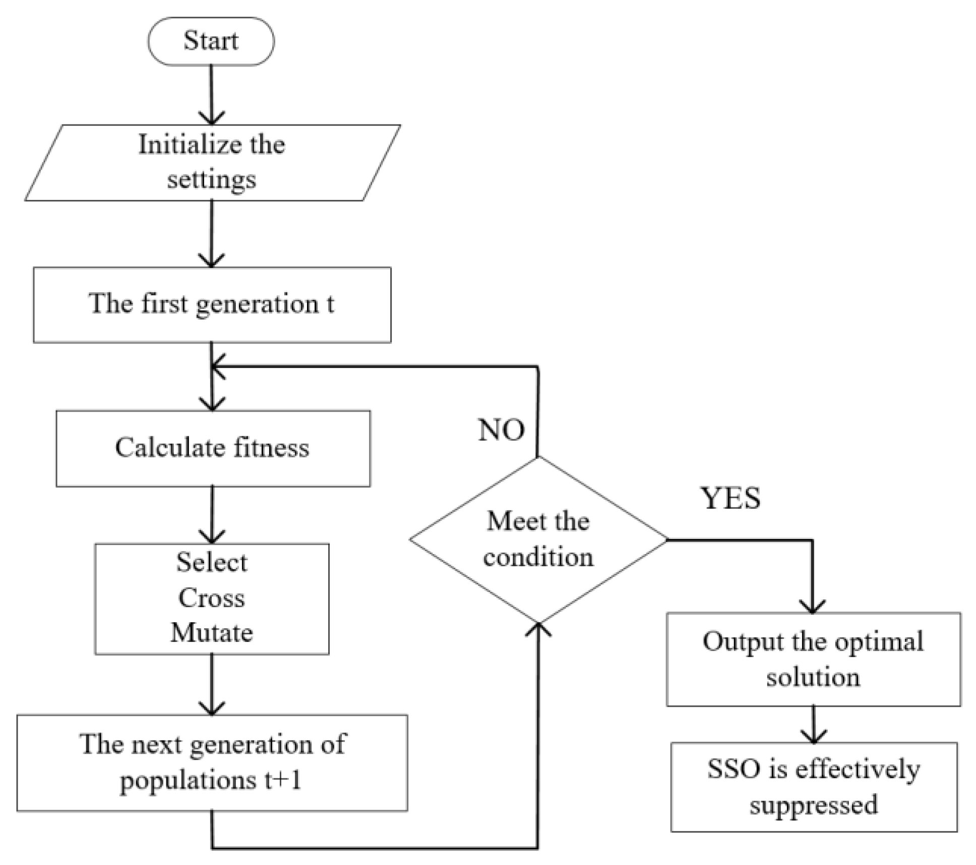
The genetic algorithm(GA) is a method of searching for the optimal solution in a probabilistic manner by simulating the natural evolutionary process[22]. Through mathematical methods and computer simulation operations, the problem-solving process is transformed into a process similar to the selection, crossing, and mutation of chromosome genes in biological evolution, and the optimal solution to the problem is obtained after several iterations and updates.
The parameter optimization method based on genetic algorithm takes the fitness function as the evaluation criterion, uses MATLAB programming to realize the iterative calculation of the parameters of the additional damping controller, and efficiently and quickly calculates the optimal parameters that should be set under different operation conditions to obtain the optimal suppression effect of the sub-synchronous oscillation.
The algorithm implementation steps are as follows:
- Initialize the population: select the dataset within the controllable range of the target parameters, and select the phase shift angle, gain, and serial complement degree as the „genes” that can be operated. The initial parameters are set as follows: the crossing probability Pc is 0.5, the mutation probability Pm is 0.001, and the maximum number of iterations T is five.
- Calculate the fitness values for different parameter combinations.
- The cross-matching order is randomly generated, the cross-matching sequence is determined according to the crossover probability Pc, and the cross-operation is carried out one by one to generate a new group.
- Individuals were randomly selected to determine whether the gene fragment was mutated according to the mutation probability, Pm, and the mutation operation of the single gene fragment was performed to generate a new population.
- Determine whether the suppression requirements are met; otherwise, proceed to Step 2 until the maximum number of iterations is reached, and the optimal solution is retained.
Figure 4.
Algorithm implementation step diagram.
The optimization objective of this study is to calculate the optimal setting values of the gain K and phase-shift time constant T in the SDC for any operating condition using the GA algorithm, to maximize the SSO amplitude rejection rate.
The index of the amplitude suppression rate is defined to describe the suppression effect of the SSO phenomenon under different SDC parameters. The relevant amplitude suppression rate is expressed as follows:
where Ha and Hb represent the amplitude of the oscillation of the output waveform of the a-phase current Iaa before and after the addition of the SDC, respectively.
A mathematical model for parameter optimization is developed as shown in Equation(10):
5. Simulation and Verification of SDC Inhibition Effect
5.1. Simulation and Verification of the Suppression Effect of SDC Add into the Control System
The SDC are installed in the abc axis control structure at the output of the GSC and RSC, and are enabled simultaneously.
In order to verify that the proposed optimization method can effectively suppress SSO under all working conditions, the time domain simulation was carried out with parameters such as gain and phase-shift time constant in SDC as variables. Table 2 lists the parameters of DFIG. The rated power and voltage of the stator were selected as the reference values. Iaa is the phase A current of the bus on the grid side The following working conditions are taken as an example for simulation experiments. The wind speed was set to 6 m/s, the capacity of each DFIG was 1.5 MW, and the number of wind turbines was 100, which were connected to the infinite power grid through the series compensation capacitor of 445F. As shown in Figure 5, the proposed method is tested with RTLAB platform.
The SDC gains Kg and Kr installed in both GSC and RSC, as well as the phase shift time constants Tg and Tr, are calculated from the GA. The current waveform without SDC under the same operating conditions was compared, and the amplitude suppression rate β was calculated according to Equation(9), which is shown in Table 6. Figure 6 and Figure 7 show the comparison of the current Iaa output waveform of phase A before and after adding SDC; the red line in the figure is the Iaa output waveform before adding the SDC, and the blue line is the Iaa output waveform after SDC is added.

Table 3.
GSC+RSC-SDC Parameters And Results.
| Number | Kg | Tg | Kr | Tr | β |
| 1 | -64 | 0.99 | -110 | 0.99 | 84.70% |
| 2 | -68 | 0.99 | -120 | 0.99 | 85.15% |
| 3 | -10 | 0.2 | -30 | 0.2 | 37.14% |
| 4 | -25 | 0.5 | -60 | 0.5 | 65.58% |
| 5 | -50 | 0.8 | -70 | 0.8 | 78.22% |
| 6 | -64 | 0.95 | -100 | 0.95 | 85.99% |
After many experiments and analyses of the experimental results, the following conclusions were obtained:
- To achieve optimization, under this working condition, the value range of the SDC gain Kg in the GSC is [-10, -64], the value range of the SDC gain Kr in the RSC is [-30, -120], and the value range of the phase-shift time constant T in the two control systems is [0.2, 0.99].
- The gain K is related to the phase-shift time constant T, and the parameters should be synchronously increased or decreased. When the absolute value of K is extremely large and that of T is extremely small, the system becomes unstable. When the absolute value of K is too small and that of T is too large, the inhibition effect is extremely insignificant, as shown in Figure 8.
- When the absolute values of K and T were increased, the inhibition effect was better. The combined inhibition effect was the best at 85.99% when Kg= -50,Tg= 0.8,Kr= -70 340 and Tr= 0.8, as shown in Figure 7.
5.2. Simulation and Verification of the Suppression Effect of SDC Injected into the Control System Alone
In this study, SDC is injected into the GSC and RSC control systems, the suppression effect is explored through simulation experiments, and a comparison table between the parameters and the SSO amplitude suppression rate is obtained. The three-dimensional diagram is drawn with code in MATLAB, as shown in Figure 9 and Figure 10 so that the relationship between the parameter setting and the suppression effect can be intuitively seen.
Comparing the inhibition effect with that of the combined injection of SDC, as shown in Table 4, it can be concluded that the joint inhibition effect when SDC is added to both the GSC and RSC systems is better than that of SDC alone in the control system under the same conditions.
6. Conclusions
To solve the SSO problem, this paper proposes an optimized additional damping method for the rotor and grid side control system of the DFIG, which can suppress the SSO successfully under variable operating conditions. First, the impedance model of the DFIG is established. Subsequently, a joint optimization strategy with SDC on both the grid and the rotor sides is proposed. Finally, the model is verified. The verification results show the following::
- An innovative optimization method based on coordinated control of the rotor and grid sides was proposed. Compared with the method of adding an additional damping controller on only one side of the rotor or grid control system, the combined optimization effect is better, with an amplitude suppression rate reaching 85.99%, which can more effectively solve the SSO problem existing in the doubly-fed wind power grid-connected system via series compensation.
- The genetic algorithm was used to optimize the design of the parameters of the additional damping controller. Through the optimization algorithm, optimized suppression under all working conditions can be achieved with different series compensation degrees, wind speeds, and the number of wind turbines.
- The experimental module was established on the RTLAB platform to simulate the experimental effects under different working conditions and conduct the simulation research. The experimental results are consistent with theoretical derivations, and the experimental conclusions provide a reference value for the setting of various parameter thresholds in engineering practice.
In summary, the SSO suppression method for doubly-fed wind turbines based on the GA proposed in this paper has a certain practical application value in addressing the challenges of power system stability and security, and also features both economy and convenience. It provides a guarantee for the safe and stable operation and efficient power transmission of wind farms and offers new ideas for the integration of artificial intelligence into new power systems.
Author Contributions
Conceptualization, Hui Huang and Yuhan Xie; methodology, Xu Zhang; validation, Jun Ye and Shenbing Ma; formal analysis, Lintao Gao; investigation, Qiman Xie; data curation, Yuhan Xie; writing—original draft preparation, Yuhan Xie; visualization, Xu Zhang; supervision, Xu Zhang. All authors have read and agreed to the published version of the manuscript.
Funding
This research was supported by Beijing NaturalScience Foundation(3232051), Beijing NaturalScience Foundation(L244005), the National Natural Science Foundation of China(52107135) and the Fundamental Research Funds for the Central Universities(2024ZKPYJD07).
Acknowledgments
Thanks Ms. Feiran Zhang for conducting the preliminary research for this article.
References
- Y. Liu, Z. Wang, H. Shen, Q. Wei, Q. Li and X. Zhang, „The research of the superconducting magnetic energy storage model based on the real time digital system,” 12th International Conference on Renewable Power Generation (RPG 2023), Shanghai, China, 2023, pp. 753-760. [CrossRef]
- Yang, W., Liao, K., Xiao, X., & Luo, C. (2018). Impact of Shunt reactor to DFIG Connected to Series-Compensated Power System on Sub-synchronous Oscillation Characteristics.
- H. Ren, B. Hou, G. Zhou, L. Shen, C. Wei and Q. Li, „Variable Pitch Active Disturbance Rejection Control of Wind Turbines Based on BP Neural Network PID,” in IEEE Access, vol. 8, pp. 71782-71797, 2020. [CrossRef]
- L. Dong, J. Kong, J. Feng and Y. Zhang, „Sub-synchronous Resonance Mitigation for Series Compensation Transmission System of DFIG Based on PR Control,” 2019 IEEE 10th International Symposium on Power Electronics for Distributed Generation Systems (PEDG), Xi’an, China, 2019, pp. 734-738. [CrossRef]
- Chen Xin, Wang Yuncheng, Gong Chunying, et al. Overview of Stability Analysis of Grid-Connected Inverters Using Impedance Analysis Method[J]. Proceedings of the Chinese Society for Electrical Engineering, 2018, 38(7): 2082-2094.
- SUN J.Impedance-based stability criterion for grid-connected inverters[J].IEEE Transactions on Power Electronics,2011,26(11):3075-3078.
- Zhen Zijing, Du Wenjuan, Wang Haifeng. Equivalence Proof of the Complex Torque Coefficient Method and Open-Loop Mode Stability Criterion in Strong Modal Coupling Phenomenon[J]. Proceedings of the Chinese Society for Electrical Engineering, 2019, 39(08): 2272-2279+10.
- Wang, Y., Yu, H., Liu, Z., Ma, Y., Zhao, G., & Deng, Z. (2019). Broadband Sub-synchronous Signal Extraction and Analysis of the Key Parameters. 2019 4th IEEE Workshop on the Electronic Grid (eGRID), 1-6.
- WEN B,BOROVEVICH D,BURGOS R,et al.Analysis of D-Q small-signal impedance of grid-tied inverters[J].IEEE Transactions on Power Electronics,2016,31(1):675-687.
- XIE X, ZHANG X, LIU H, et al.Characteristic analysis of sub-synchronous resonance in practical wind farms connected to series-compensated transmissions[J].IEEE Transactions on Energy Conversion,2017,32(3):1117-1126.
- ]Ma Ningning, Du Weizhu, Liu Pengyin, et al. Risk Assessment of Sub/Super-Synchronous Oscillation for Wind Power Based on Hardware-in-the-Loop Testing[J]. Proceedings of the Chinese Society for Electrical Engineering, 2022, 42(15): 5497-5506. [CrossRef]
- VIETO I, SUN J.Sequence impedance modeling and analysis of type-Ⅲ wind turbines[J].IEEE Transactions on Energy Conversion,2018,33(2):537-545.
- Y. Tian, Y. Liu, Z. Xiao, Z. Wang, Y. Geng and D. Zhao, „Research on Construction Scheme of New Generation Centralized Control Station Intelligent Monitoring System,” 2023 3rd International Conference on Energy Engineering and Power Systems (EEPS), Dali, China, 2023, pp. 1004-1009. [CrossRef]
- Wang Yijun, Du Wenjuan, Chen Chen, Wang Haifeng. Study on Sub-synchronous Oscillation in Power Systems Caused by Wind Farms Connected to the Grid Based on Improved Complex Torque Coefficient Method[J]. Journal of Electrical Engineering, 2020, 35(15): 3258-3269.
- MIAO Z. Impedance-model-based SSR analysis for type 3 wind generator and series-compensated network[J].IEEE Transactions on Energy Conversion,2012,27(4):984-991.
- Research on the Impact on Sub-synchronous Resonance Risk from DFIG Number and Series-compensated Degree M X Yin, H Liu, Y H Li, W Song. „Research on the Impact on Sub-synchronous Resonance Risk from DFIG Number and Series-compensated Degree”, Journal of Physics: Conference Series, 2018September 2018Journal of Physics Conference Series 1087(4):042075DOI:10.1088/1742-6596/1087/4/042075.
- X. Zhang et al., „Risk prediction of sub-synchronous oscillation based on the black-box impedance model of DFIG for multiple operating conditions,” 12th International Conference on Renewable Power Generation (RPG 2023), Shanghai, China, 2023, pp. 686-693. [CrossRef]
- Y. Chi, Y. Liu, W. Wang and H. Dai, „Voltage Stability Analysis of Wind Farm Integration into Transmission Network,” 2006 International Conference on Power System Technology, Chongqing, China, 2006, pp. 1-7. [CrossRef]
- Ghennam, Tarak et al. “DC-link voltage balancing algorithm using a space-vector hysteresis current control for three-level VSI applied for wind conversion system.” 2007 European Conference on Power Electronics and Applications (2007): 1-10.
- Liu Huakun, Xie Xiaorong, He Guoqing, et al. Impedance Modelling in Synchronous Reference Frame and Stability Discrimination Method for Grid-Connected New Energy Generation Systems[J]. Proceedings of the CSEE, 2017, 37(14): 4002-4007.
- ]Li Yixin, Zhao Shuqiang, Ma Yanfeng, et al. Impedance Modelling and Characteristic Analysis of Three-Phase LCL Grid-Connected Inverter[J]. Electric Power Automation Equipment, 2019, 39(7): 107-113.
- Xu Y, Zhao S. Mitigation of Sub-synchronous Resonance in Series-Compensated DFIG Wind Farm Using Active Disturbance Rejection Control[J].IEEE Access 2019,7:,68812-68822.
Figure 1.
The topology of the doubly-fed wind turbine is connected to the grid through series supplementation with SDC connected to both rotor-side and grid-side.
Figure 1.
The topology of the doubly-fed wind turbine is connected to the grid through series supplementation with SDC connected to both rotor-side and grid-side.
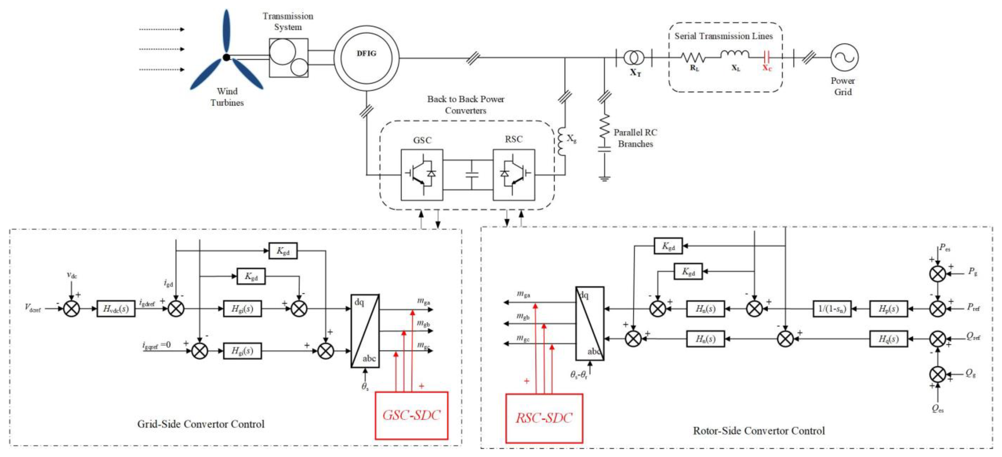
Figure 2.
System impedance modeling.
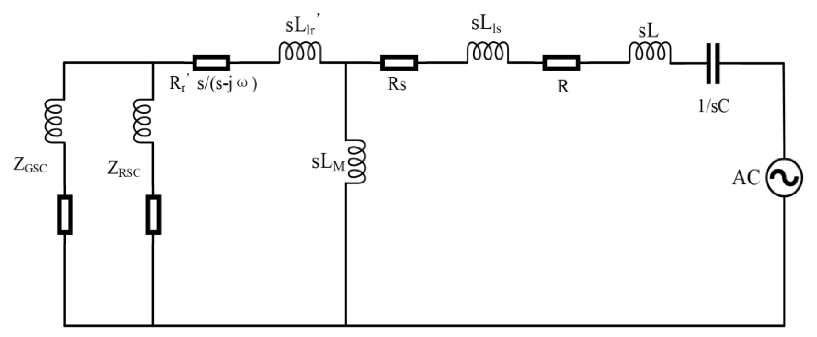
Figure 3.
Impedance schematic with SDC added.
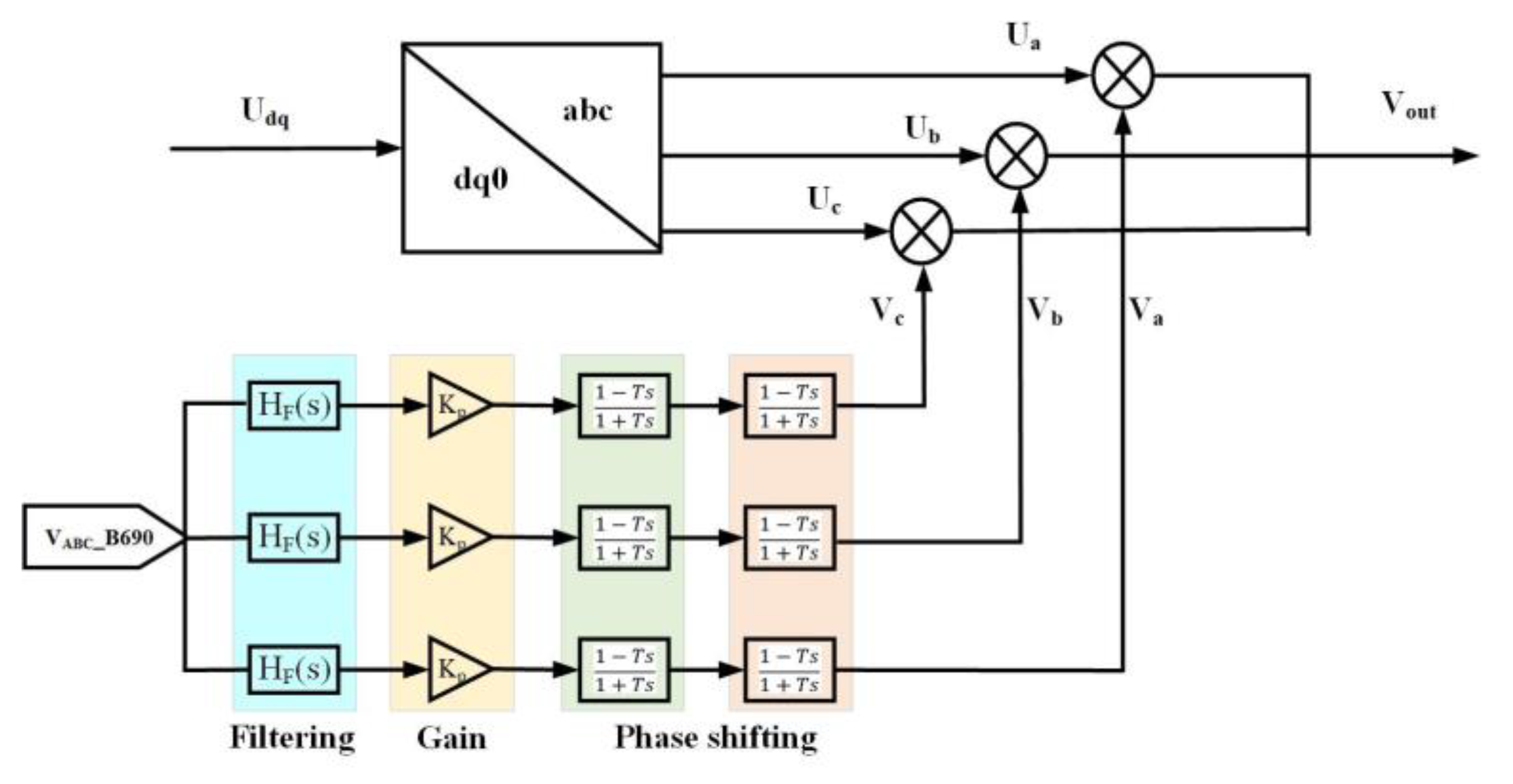
Figure 5.
Testing with RTLAB platform.
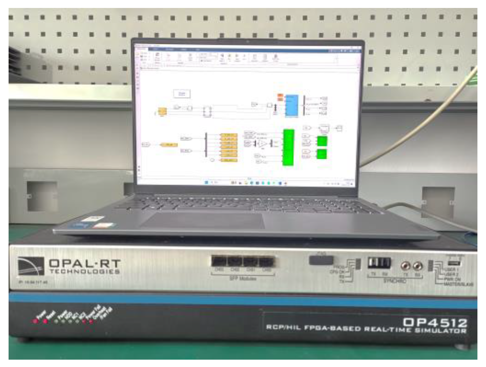
Figure 6.
Comparison of Iaa output waveforms of the SDC only added in the GSC.
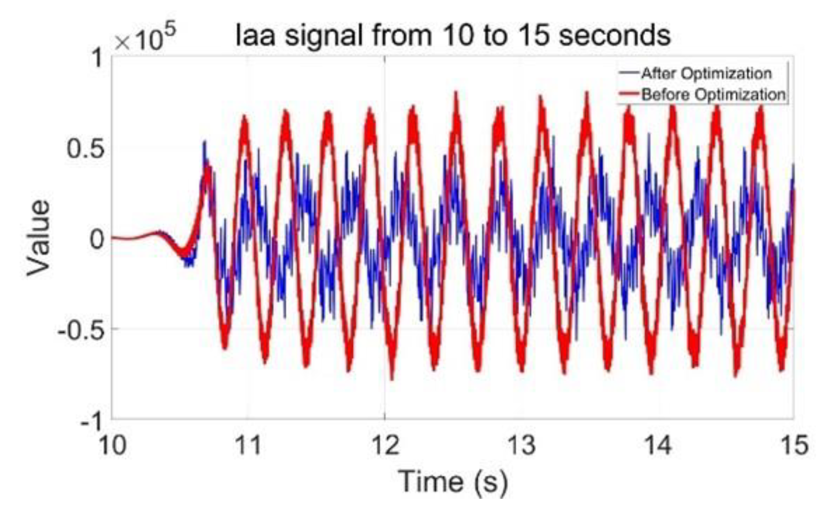
Figure 7.
Comparison of Iaa output waveforms with the joint addition of SDC in GSC and RSC.
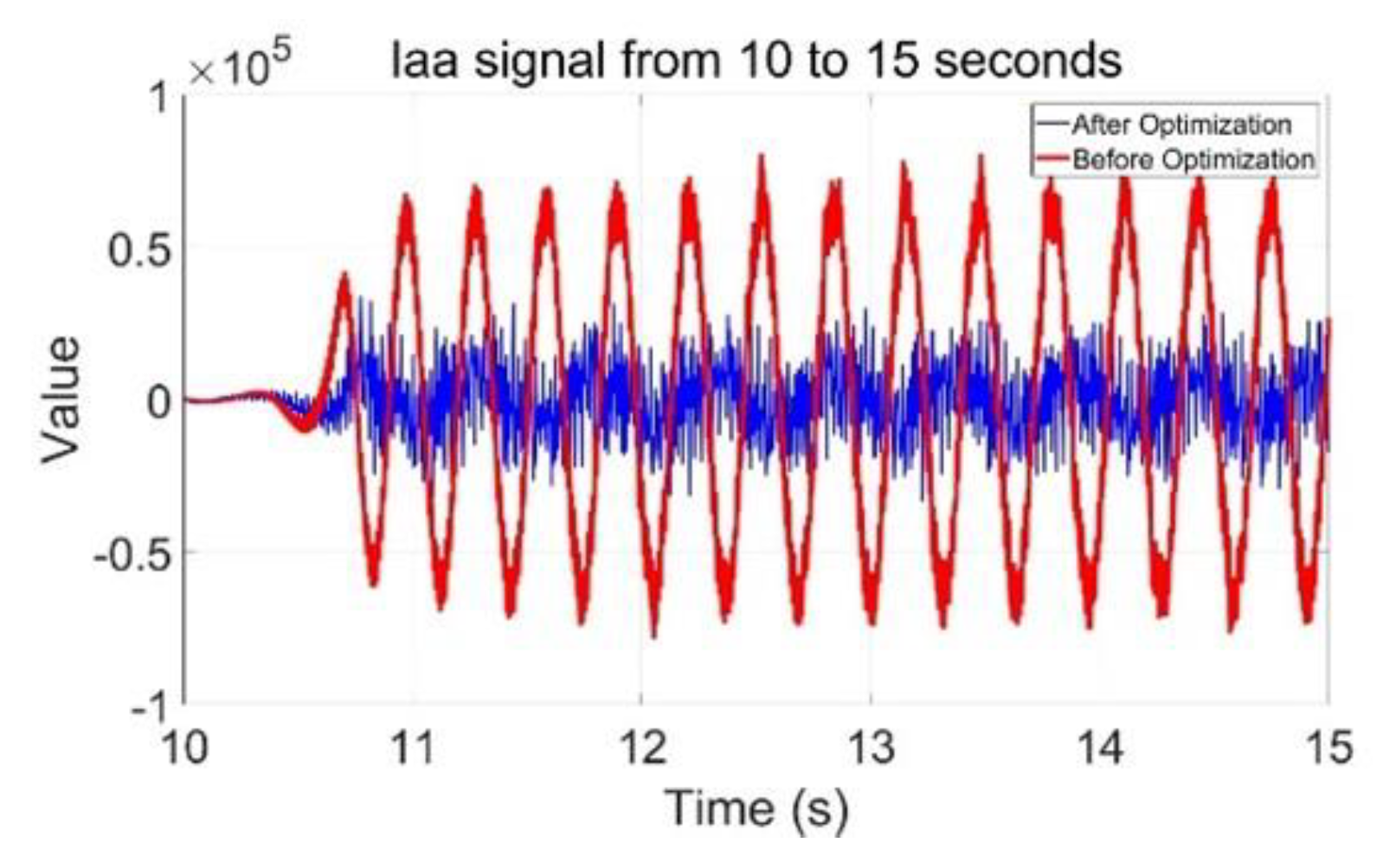
Figure 8.
Invalid verification.
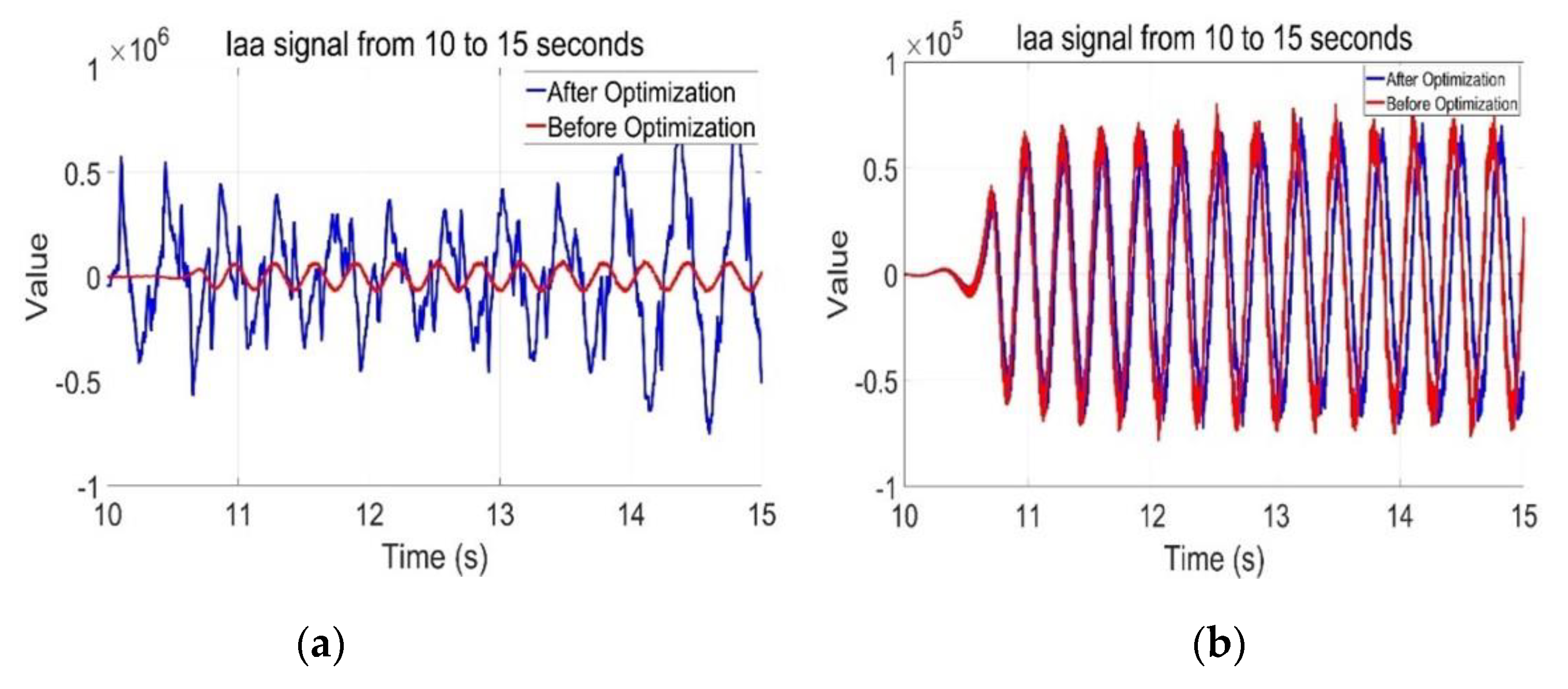
Figure 9.
GSC parameter settings and results.
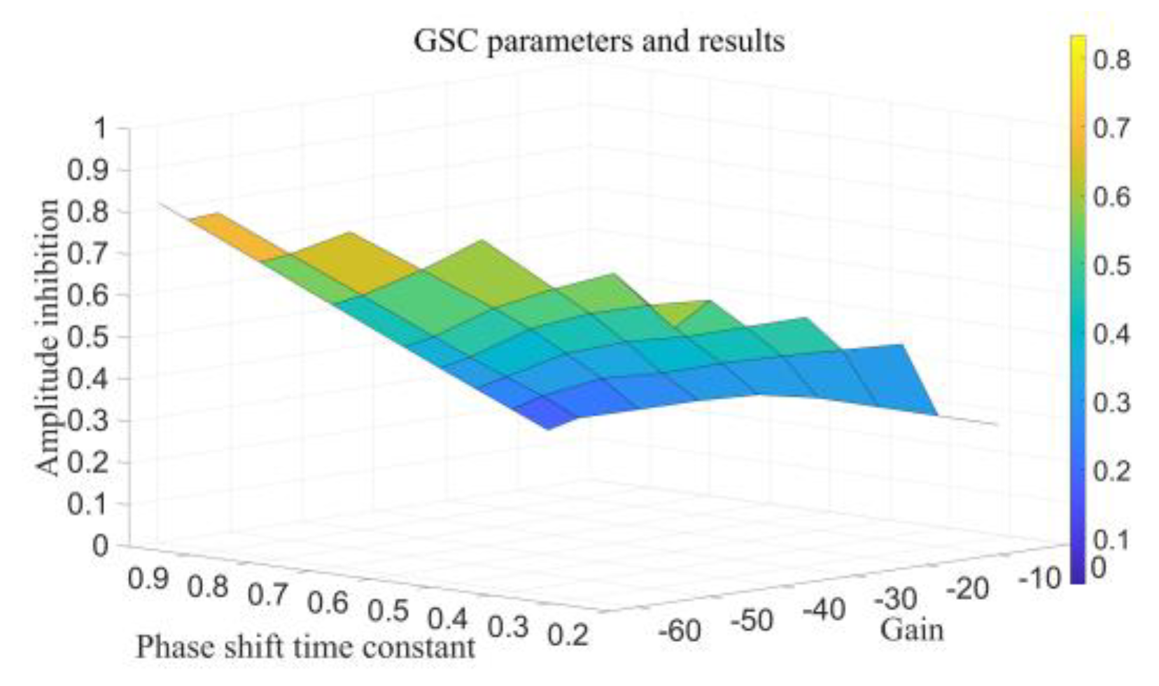
Figure 10.
RSC parameter settings and results.
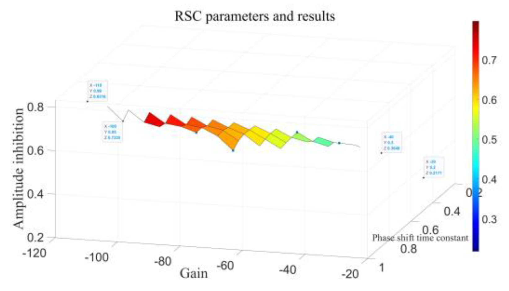
Table 1.
Meaning of each physical quantity in (1)- (2).
| Parameter | Meaning | Parameter | Meaning |
| GSC three-phase AC modulation voltage | PWM Gain | ||
| RSC three-phase AC modulation voltage | Stator and rotor turns ratio | ||
| DC voltage | GSC three-phase AC modulation signal | ||
| Three-phase AC voltage | GSC three-phase AC current |
Table 2.
DFIG Parameters.
| Parameter | Value | Parameter | Value |
| Rated power | 1.5 MW | Rotor resistance | 0.01827 p.u. |
| Rated frequency | 50 Hz | Rotor self-sensing | 0.2222 p.u. |
| Stator rated voltage | 0.690kV | Excitation inductance | 15.71 p.u. |
| Rotor rated voltage | 1.975kV | Stator resistance | 0.01638 p.u. |
| Constant of inertia | 0.0685 s | Stator self-sensing | 0.2552 p.u. |
| GSC scale factor | 0.83 | GSC points factor | 5 |
| RSC scale factor | 0.6 | RSC points factor | 8 |
Table 4.
Comparison Of The Effects Of Different SDC Addition Positions.
| Group | SDC location | Kg | Tg | Kr | Tr | β |
| 1 | GSC | -10 | 0.2 | - | - | 31.09% |
| RSC | - | - | -30 | 0.2 | 21.77% | |
| GSC+RSC | -10 | 0.2 | -30 | 0.2 | 37.14% | |
| 2 | GSC | -25 | 0.5 | - | - | 58.88% |
| RSC | - | - | -60 | 0.5 | 52.73% | |
| 3 | GSC+RSC | -25 | 0.5 | -60 | 0.5 | 65.58% |
| GSC | -50 | 0.8 | - | - | 75.72% | |
| RSC | - | - | -70 | 0.8 | 56.27% | |
| GSC+RSC | -50 | 0.8 | -70 | 0.8 | 78.22% | |
| 4 | GSC | -64 | 0.95 | - | - | 83.31% |
| RSC | - | - | -100 | 0.95 | 73.35% | |
| GSC+RSC | -64 | 0.95 | -100 | 0.95 | 85.99% |
Disclaimer/Publisher’s Note: The statements, opinions and data contained in all publications are solely those of the individual author(s) and contributor(s) and not of MDPI and/or the editor(s). MDPI and/or the editor(s) disclaim responsibility for any injury to people or property resulting from any ideas, methods, instructions or products referred to in the content. |
© 2024 by the authors. Licensee MDPI, Basel, Switzerland. This article is an open access article distributed under the terms and conditions of the Creative Commons Attribution (CC BY) license (http://creativecommons.org/licenses/by/4.0/).
Copyright: This open access article is published under a Creative Commons CC BY 4.0 license, which permit the free download, distribution, and reuse, provided that the author and preprint are cited in any reuse.


