Submitted:
31 May 2025
Posted:
02 June 2025
You are already at the latest version
Abstract
High-speed trains have revolutionized modern transportation with their exceptional speeds, yet the essence of this technological breakthrough resides in the train's wheels. These meticulously engineered components are deliberately designed to endure extreme mechanical stresses while ensuring uncompromising safety and reliability. In this paper, we selected the rim and web as representative components of the wheel and conducted a comprehensive and systematic study on their microstructure and mechanical properties. The wheels are typically produced through integral forging. To improve the mechanical performance of the wheel/rail contact surface, i.e. tread in the wheel, the rim is subjected to surface quenching or other heat treatments. This endows the rim with strength and hardness second only to the tread, while also reducing its texture intensity and ductility, resulting in nearly isotropic characteristics and better fatigue resistance in low-cycle and high-cycle regimes under rotating bending. The web connects the wheel axle to the rim and retains the pronounced texture formed during the forging process. Its strength is lower than that of the rim, while its ductility is slightly better. This indicates that there is still considerable potential to tailor the mechanical properties of the web through heat treatment.
Keywords:
high-speed train wheel
; steel
; microstructure
; hardness
; tension
; low-cycle fatigue
; high-cycle fatigue
; rotating bending
; fatigue limit
; staircase method
1. Introduction
According to Refs. [1-4], high-speed rail refers to a rail transport network that uses trains operating at speeds significantly higher than traditional rail, supported by an integrated system of specialized rolling stock and dedicated tracks. While there is no universal definition or standard, lines designed to manipulate speeds of at least 250 km/h, or upgraded lines with speeds of at least 200 km/h, are generally considered high-speed. In China, high-speed rail is classified as newly constructed passenger lines with a design speed of 250 km/h or more, and a minimum initial operating speed of 200 km/h [5,6]. In historical terms, the inaugural high-speed rail system was the Japan’s Tōkaidō Shinkansen, launched in 1964. Contrarily, China’s high-speed rail development, though starting later, has undergone unprecedented expansion, culminating in an operational network spanning 45,000 km by the end of 2023 and solidifying its position as the global leader in both infrastructure scale and technological adoption [7,8].
For high-speed rail applications, train wheels are typically manufactured [9,10] as monobloc components via forging, utilizing specialized steel grades [11,12] that provide a balanced combination of strength [13-15], ductility [13-17], fracture toughness [14,15], and fatigue resistance [18-41]. These wheels operate under complex and demanding service conditions, including high-speed rolling contact [42-44], thermal cycling [44-47] caused by braking, and dynamic loads resulting from track irregularities [48]. Structurally, a wheel consists of three primary regions: the tread (or running surface), the rim, and the web, each subjected to distinct mechanical and thermal conditions. The rim, in particular, experiences elevated contact stresses and is often subjected to surface hardening treatments to enhance fatigue resistance [49-51]. Recently, additive manufacturing [52-60] has been more and more popularly applied in the repairment of wheels.
In contrast, the web primarily sustains bending stresses and retains more of the forged texture. Therefore, a comprehensive understanding of the microstructural and mechanical property variations across these regions is essential for optimizing wheel performance and ensuring long-term reliability [19-28,37-39] in high-speed rail service.
High-speed rail wheel steel is a specialized steel used for manufacturing wheels of high-speed rail trains. These wheel steels must meet the high demands of high-speed operation, frequent starts and stops, and complex track conditions, and therefore possess characteristics such as high strength, high toughness, high wear resistance, and good resistance to thermal cracking.
The wheels of high-speed trains represent a critical engineering interface between rolling stock and rail infrastructure, where the rim and web regions endure distinct yet interconnected thermomechanical challenges during operation. The rim, subjected to intense friction, cyclic thermal loading, and wear from wheel-rail contact, demands a microstructure optimized for surface hardness, fatigue resistance, and thermal stability. In contrast, the web, functioning as a structural mediator between the rim and hub, must balance dynamic load transmission with resistance to crack propagation while minimizing weight. Both regions rely on tailored steel microstructures—governed by phase distribution, grain refinement, and carbide precipitation—to achieve site-specific mechanical properties such as strength-toughness synergy, stress corrosion resistance, and damping capacity. However, the heterogeneous thermomechanical histories imposed during manufacturing and service often induce microstructural gradients between these zones, potentially compromising performance under extreme speed and load conditions. This study systematically examines the microstructural architectures and their mechanical manifestations in the rim and web of high-speed train wheels, employing multiscale characterization and mechanical testing to unravel location-dependent degradation mechanisms. The findings aim to advance the design of functionally graded wheel materials that harmonize the conflicting performance requirements of these critical regions.
2. High-Speed Train Wheels
2.1. Background
The wheelset, comprising the wheel and axle, is critical for high-speed rail safety and performance. The rim, as the contact surface with the rail, undergoes precision forging and heat treatment to withstand extreme thermomechanical loads. Its profile (e.g., conical or concave) optimizes steering stability and wear resistance. The web plate (or spoke) connects the rim to the hub, engineered with radial ribs or hollow structures to balance lightweight design with fatigue resistance. Advanced materials like EA4T alloy steel enhance strength-to-weight ratios, while ultrasonic testing ensures metallurgical integrity. This integrated design minimizes vibrations and derailment risks at speeds exceeding 350 km/h.
High-speed train wheel rim is an important part of high-speed railway wheel, and the introduction about high-speed railway wheel rim can be summarized as follows: rim is the outer edge part of the wheel, which is located in the tread surface of the wheel along the radial direction (towards the center of the circle) in the area of a certain thickness. It is in direct contact with the railway track and bears the pressure and friction when the train is running. The quality of the rim determines the quality of the wheel to a large extent, because the rim mass accounts for a larger proportion of the wheel mass. Its hardness and wear resistance directly affect the service life of the wheel. High-speed railway wheels are usually made of high-strength and high-toughness alloy steel material, which can withstand the huge pressure and friction when the train is running at high speed. In order to improve the hardness of the rim to increase its service life, the tread of the wheel will be quenched. However, the characteristics of the hardening process limit the depth of hardening, and the thicker the rim, the lower the internal hardness is likely to be. The thickness of the rim needs to be designed taking into account the service life, the weight of the wheel and the difference in diameters between old and new wheels. The thicker the rim, the greater the effective wear thickness, the longer the service life of the wheel theoretically, but at the same time it will also increase the weight of the wheel, and have an impact on the vertical movement of the wheel and rail force. China's railway wheel judgement is mainly based on the remaining thickness of the rim. When the remaining thickness of the rim is less than or equal to 23 mm, the wheel needs to be scrapped.
2.2. Material Composition
The chemical composition of the high-speed train wheel steel, as listed in Table 1, indicates a well-balanced low-alloy medium-carbon design tailored for enhanced fatigue and wear resistance. The measured carbon content is 0.54 wt.%, slightly below the upper limit (≤ 0.56 wt.%), contributing to adequate hardness and strength required for high-cycle loading while maintaining acceptable toughness. Silicon and manganese levels, at 0.30 wt.% and 0.75 wt.% respectively, are within the specified range, supporting solid solution strengthening and deoxidation during processing. The low phosphorus (0.013 wt.%) and sulfur (0.007 wt.%) contents reflect effective control of impurity elements, which is critical for minimizing embrittlement and improving the fatigue performance, especially under VHCF regimes.
Notably, the cumulative content of Cr, Ni, and Mo amounts to 0.32 wt.%, significantly below the upper limit of 0.50 wt.%, suggesting a moderate alloying strategy. This combination enhances hardenability and tempering resistance without significantly increasing the risk of internal inclusions or cost. The presence of Cr (0.18 wt.%) and Mo (0.04 wt.%) improves the steel’s resistance to softening during thermal cycling and contributes to secondary hardening, which is advantageous in fatigue-dominated applications. The trace amount of vanadium (0.003 wt.%) may support grain refinement and precipitation strengthening, although its low level suggests a minimal effect.
Overall, the composition reflects a carefully optimized design to balance strength, toughness, and fatigue resistance, making it suitable for the demanding service conditions of high-speed railway applications.
2.3. Manufacturing and Sampling
The high-speed train wheelset, as illustrated in Figure 1a, consists of a forged axle, two wheels, and associated components such as the tread, flange, rim, and web. The wheel itself is a monoblock forged steel component, designed to withstand dynamic service loads, rolling contact stresses, and severe environmental conditions. The manufacturing process typically involves vacuum degassing, hot forging, followed by controlled cooling and heat treatment processes (e.g., quenching and tempering), which are critical for achieving the desired combination of strength, toughness, and fatigue resistance.
To evaluate the mechanical properties and microstructural uniformity of the wheel, material sampling was conducted at two critical regions, as shown in Figure 1b. These include the web region and the rim region, which are subjected to different stress states during service. The rim, particularly the tread and flange area, is exposed to cyclic rolling contact and wear, making it the most fatigue-critical zone. A cross-sectional schematic indicates that rim samples were taken 15 mm below the tread surface and from a location near the inner surface of the flange. In contrast, web samples were extracted near the central axis of the wheel plate. These locations were strategically selected to assess variations in microstructure and mechanical response due to the wheel’s geometry, thermal gradients during manufacturing, and in-service stress distributions.
3. Microstructure Characterizations
3.1. Texture Observations
The cross-sectional microstructure perpendicular to the wheel’s radial direction was examined optically under different magnifications and locations. Figure 2a at a low magnification, i.e. 500 μm scale, shows a rolling-induced elongated grain structure, suggesting a preferred crystallographic orientation marked by the red arrow. This texture is typical of steels or ferritic-pearlitic alloys subjected to hot or cold rolling, where grain elongation aligns along the rolling direction. Upon cooling, austenite transformed into ferrite and pearlite. Pearlite formation likely initiated along austenite grain boundaries, which can be identified more clearly in Figures 2b–d. Figures 2b–d give higher magnification images, i.e. 200–50 μm scale, showing ferrite (α-Fe) and pearlite colonies marked by the yellow arrows. Ferrite appears as equiaxed light-grey regions, whereas pearlite appears as darker, lamellar regions formed by eutectoid decomposition of austenite.
This observation results from a transformation from austenite into ferrite and pearlite during cooling when pearlite formation initiated along austenite grain boundaries. The dominant ferrite-pearlite structure offers a balance between strength and ductility, ideally suitable for structural applications, specially manufacturing high-speed train wheels. Pearlite, with its lamellar cementite and ferrite, is harder and tends to concentrate stress, making it a preferential site for fatigue crack initiation, especially under high-cycle fatigue conditions. The interfaces between ferrite and pearlite can be taken as mechanical heterogeneities, which localize microplastic strain and promote slip incompatibility leading to persistent slip bands (PSBs) initiation that evolves into microcracks. Due to probable insufficient secondary refining, inclusions marked by the blue arrows are present in various locations and may represent oxides, sulfides, or non-metallic particles introduced during solidification. They serve as stress concentrators, potentially reducing fatigue resistance and ductility. Crack initiation often begins at the inclusion–matrix interface, especially under rotating bending or axial fatigue conditions, which is exactly the case concerned about in this paper.
3.2. Optical Light Microscopy
Figure 3 shows the metallographs of wheel rim perpendicular to the wheel’s axis under different magnifications and locations. Figure 3a–b both give a general pattern of fine-grained and equiaxed texture under low magnifications. The bright areas are pearlite colonies, and the dark area is ferrite contrarily, which can be seen more clearly in Figures 3c–d. No elongated grains or textures are apparent, indicating equiaxed grains. This can be also confirmed by Figure 4, which shows the metallographs of wheel rim parallel to the wheel’s axis under different magnifications and locations.
Similarly, in Figure 4, the characteristics of equiaxed grains can be identified even more clearly. The refined ferrite–pearlite microstructure showing a uniform phase distribution suggests effective control of thermo-mechanical processing, which usually achieves a favorable combination of strength and ductility and isotropic mechanical behavior. This is typically used in manufacturing high-speed rail wheel rims, which can prevent the formation of bainite or martensite, ensuring ductility is preserved while maintaining adequate hardness. From a fatigue perspective, such a dual-phase structure enhances crack initiation resistance due to ferrite's plastic accommodation and retards propagation through tortuous ferrite–pearlite interfaces, making it well-suited for high-cycle rolling contact fatigue conditions in high-speed rail wheel rims. Rolling contact fatigue from train–rail interaction is the most important part needed to be concerned about even though thermal fatigue and cyclic bending and tension/compression also contribute a lot to the failure. Since no obvious defects or inclusions can be identified in the figures, crack initiation likely occurs at ferrite–pearlite interfaces due to mismatch in hardness. Furtherly, crack propagation occurs more easily through pearlite regions, particularly if lamellae are coarse or misaligned with load direction.
3.3. Scanning Electron Microscopy
Figure 5 and Figure 6 give a much clearer picture of the microstructure with the help of SEM. Figure 5 shows the SEM images of wheel rim perpendicular to the wheel’s axis under different magnifications and locations. Similarly, Figure 6 shows the SEM images of wheel rim parallel to the wheel’s axis under different magnifications and locations. Both Figures 5a and 6a show a ferrite–pearlite matrix with clearly defined pearlite colonies. The colony boundaries are visible, and their size appears relatively small and uniformly distributed, indicating controlled cooling and fine transformation structures. Inclusions, marked in blue, can be identified more clearly in Figure 6a. Some discontinuities are visible in Figure 5b, which potentially compromises the mechanical performance. The inclusions show elongation or alignment, indicating they may have been stretched during hot rolling, which aligns with the wheel’s axial direction. In Figure 5c and 6c, a well-developed lamellar pearlite structure is evident, with alternating ferrite (dark area) and cementite (bright area) lamellae. The morphology of pearlite colonies and cementite alignment indicates that the steel underwent eutectoid transformation from austenite during controlled air cooling or normalizing. The inclusion can be clearly identified in both the figures, which creates a stress concentration site and probably becomes an origin for crack initiation during service. Figure 5d and 6d are taken under a high magnification, i.e. 1 μm scale. The bonelike pearlite lamella appears uniform, parallel, and closely spaced, which is favorable for mechanical performance. Narrow interlamellar spacing enhances strength and fatigue resistance but may compromise ductility under low-cycle fatigue. In Figure 6d, narrower interlamellar spacing is visible due to a different structure orientation, compared with Figure 5d. The ferrite–pearlite interface introduces mechanical heterogeneity, potentially leading to persistent slip band formation and early crack nucleation. The longitudinal (axial) orientation of pearlite lamellae increases anisotropy in fatigue resistance. Thus, fatigue cracks may grow faster parallel to lamella but are deflected or blunted by lamella interfaces when they propagate perpendicularly.
4. Mechanical Behavior Analyses
4.1. Microhardness
Based on Figure 7, which presents the Brinell hardness (HBW) distributions across different longitudinal sections of a wheel rim, both the mechanical consistency and process-induced variation of the wheel rim material can be analyzed, which is critical for understanding its performance in service, especially under fatigue loading, rolling contact, and thermal cycling. The hardness distribution reflects a ferrite–pearlite microstructure, as confirmed in previous figures. Higher hardness zones (outer rim) are most likely dominated by fine pearlite with narrow lamellar spacing and beneficial for wear resistance and rolling contact fatigue resistance. Lower hardness zones (inner rim) have higher ferrite fraction with larger grain sizes. This part provides ductility and toughness, improving resistance to impact and thermal fatigue. Both higher hardness zones and lower hardness zones play important roles in enhancing damage tolerance. Hard outer layers resist wear and surface fatigue and softer core absorbs plastic deformation and retards crack propagation.
Each subfigure of Figure 7 represents a different longitudinal section of the wheel rim. The measured hardness values range from approximately 245 HBW to 291 HBW. A general trend can be concluded on all the sections: the outer rim surface (tread region) consistently exhibits higher hardness (~278–291 HBW), while the inner regions (closer to the hub or web) show slightly lower hardness (~245–260 HBW). Figure 7a shows a smooth gradient, suggesting uniform cooling and transformation with no abrupt transitions. In Figure 7b, hardness is slightly higher overall than in Figure 7a, especially in the outer shoulder and central rim zone, indicating more efficient cooling in this section. Figure 7c reveals slightly lower hardness at the base (~251–254 HBW) compared to other sections, which might pose concern for contact fatigue or bending stresses. Figure 7d gives the highest average hardness across all zones (~275–291 HBW). This section likely has the best fatigue and wear resistance but may also be more brittle if pearlite is dominant and not tempered.
4.2. Tensile Properties
For the wheel rim, the measured tensile strength is 929 MPa, well within the required range of 860–980 MPa. The measured yield strength goes to 602 MPa, comfortably above the required 540 MPa. The measured elongation after fracture is 17.0%, also exceeding the 13% threshold, indicating excellent ductility. The reduction of area comes to 46%, suggesting strong plastic deformability and damage tolerance. Good elongation and area reduction confirm the presence of ductile ferrite regions and low inclusion content, despite some alignment in inclusions seen in SEM. Similarly, for the wheel web, the measured tensile strength, 779 MPa, also falls within the acceptable range of 740–860 MPa. The measured elongation, 21.0%, exceeds the 16% threshold and the reduction of area is 42%. We can see that the web is not subject to direct wheel–rail contact, so it prioritizes toughness and ductility over strength. The wheel rim demonstrates high strength and fatigue resistance due to its fine pearlitic microstructure, while the wheel web has relatively lower strength, as this region is designed to absorb shock and flex under service loads. This complementary mechanical behavior is crucial for ensuring long-term safety and durability of high-speed rail wheels under severe operational environments.
4.3. Rotating Bending Method
In our tests, a four-point rotating bending fatigue testing method was applied. This method is ideal for wheel rim fatigue assessment under service-simulated conditions. Figure 8 shows a schematic diagram of a four-point rotating bending fatigue testing machine, which is a standard apparatus used to evaluate the fatigue strength and life of materials under controlled bending conditions. Driven by a motor, the cylindrical specimen rotates about its longitudinal axis at a constant speed. Two equal downward forces (F/2) are applied via loading points at a known distance apart. The force is applied by hanging calibrated dead weights, ensuring constant-magnitude cyclic loading. Because the specimen rotates while the load direction remains fixed, each point on the specimen’s surface experiences tensile and compressive stresses in alternating fashion, producing fully reversed cyclic bending (the stress ration R = –1) — ideal for high-cycle fatigue characterization. The test induces a rotating bending moment, generating a sinusoidal stress waveform in time. The surface of the specimen is the most highly stressed region, making it the most likely crack initiation site. This setup ensures uniform stress distribution, controlled crack initiation location, and accurate fatigue life measurement, which is directly relevant for assessing material anisotropy, microstructural effects, and hardness gradients—as seen in prior analyses.
Figure 9 presents a detailed schematic of a fatigue specimen clamping configuration and the resulting stress distribution—typically used in rotating bending fatigue tests, such as those shown in Figure 8. This type of specimen geometry and fixture is designed to ensure precise loading, controlled stress localization, and reliable fatigue failure initiation. The hourglass-shaped specimen has a reduced diameter at the central gauge section, creating a well-defined stress concentration zone, which ensures fatigue cracks initiate and propagate in a predictable location, maximizing result consistency and minimizing scatter in fatigue life data. Away from transition zones, the stress field in the gauge section is effectively uniaxial and bending-dominated, ideal for fatigue S–N curve generation. Thus, it facilitates reliable fatigue life measurement in components like high-speed train wheels.
4.4. Low-Cycle and High-Cycle Fatigue
Figure 10 presents the S–N data for two batches of specimens tested under rotating bending fatigue conditions. From Figure 10a, the global fatigue behavior of the two batch specimens can be characterized and compared. In 10⁴ and 10⁶ cycle regime, failure is observed under stress amplitudes ranging from ~400–470 MPa. It generally shows the classical S–N downward trend, which is compatible with the results in other relevant research and papers. At or below ~430 MPa, multiple specimens reached over 10⁷ cycles without failure, indicating a fatigue endurance limit in this material. The runout plateau suggests a safe stress amplitude threshold for infinite life design. The two batches (red vs. blue) largely overlap but slight scatter is observed, likely due to microstructural variations (grain size, inclusion content, and stuff) or minor processing differences. Figure 10b shows a clearer picture of the S–N data by adjusting the display ranges of the coordinate axes. Red and blue hollow dots show tighter clustering in the ~460–480 MPa range with failure occurring between 5×10⁴ and 5×10⁵ cycles. Fatigue scatter is more pronounced as stress decreases. At ~425 MPa, most specimens fail around 10⁶ cycles, while one survives 10⁷ cycles. At or below ~400 MPa, most specimens survive 10⁷ cycles. This highlights the transition zone near the fatigue limit, where small differences in surface condition, inclusions, or microstructure significantly affect fatigue life. These results are compatible with the data in Table 2. The fatigue limit can be estimated at around a half of the tensile strength by considering the materials of both the wheel rim and the wheel web, which is typical for ferrite–pearlite steels. Inclusions seen in SEM are likely responsible for failures in the ~425–460 MPa range.
4.5. Estimating Fatigue Limit by Staircases
Figure 11 presents fatigue testing results obtained using the staircase method, also called up-and-down method, a statistical technique used to estimate the fatigue limit of a material. This method usually incrementally increases or decreases stress based on the previous specimen’s outcome. If a specimen fails, the next one is tested at a lower stress level. If a specimen survives (runout), the next one is tested at a higher stress level. This creates a “stair-step” pattern from which the mean fatigue limit and standard deviation can be statistically estimated. The method and presentation offer insight into statistical fatigue strength at a fixed life level, commonly around 106 or 107 cycles. Figure 11a shows the red batch with the stress range of ~380–430 MPa. Repeated failures occur between 420–430 MPa. Runouts mostly occur around 400 MPa. The transition zone between runout and failure is ~410–420 MPa. Thus, the fatigue limit for this batch can be estimated as ~410–415 MPa. For the blue batch, following the same steps, the stress ranges from 380 MPa to 440 MPa. Clear alternation between failure and runout are near ~400–420 MPa, indicating the threshold zone. Failure cluster goes near ~430–440 MPa. Runouts occur between ~390–410 MPa. So, the estimated fatigue limit for this blue batch is ~410–420 MPa, consistent with the red batch.
The consistent fatigue limit across batches validates the reliability of processing and microstructural control. This fatigue limit can be used as the design allowable stress amplitude for wheel rim materials under infinite-life (very-high-cycle) loading conditions. The result confirms that below ~410 MPa, the material can safely survive 10⁷ cycles without failure—critical for long-life applications such as high-speed train wheels.
5. Conclusions
This study systematically investigates the microstructure and mechanical properties of high-speed train wheel rims and webs, revealing critical insights into their performance under complex service conditions. The rim, subjected to surface quenching, exhibits a fine-grained, equiaxed ferrite-pearlite microstructure with high hardness (245–291 HBW) and tensile strength (929 MPa), ensuring excellent resistance to rolling contact fatigue and wear. Its nearly isotropic behavior under rotating bending fatigue, with a fatigue limit of ~410–420 MPa, highlights the effectiveness of heat treatment in balancing strength and ductility. In contrast, the web retains a forged texture with elongated grains, lower strength (779 MPa), and higher ductility (21% elongation), making it suitable for absorbing dynamic loads and resisting crack propagation. However, its pronounced texture and potential for inclusion-induced stress concentrations indicate room for improvement through tailored heat treatments to optimize mechanical homogeneity.
Microstructural analyses confirm that ferrite-pearlite interfaces and non-metallic inclusions are primary sites for fatigue crack initiation, particularly in high-cycle regimes. The dual-phase structure of the rim enhances crack propagation resistance via tortuous interfaces, while the web’s ductility mitigates risks from bending stresses. These findings underscore the importance of gradient material design in wheel engineering, where the rim prioritizes surface durability and the web emphasizes structural flexibility. Overall, this research provides a foundational framework for enhancing wheel reliability through microstructural control and targeted heat treatments, supporting the safety and longevity of high-speed rail systems.
Author Contributions
Conceptualization, H.S.5 and H.S.6; methodology, H.S.5, C.G., Y.Z.; validation, T.F.; formal analysis, J.W.; investigation, C.G.; resources, C.G., Y.Z.; data curation, T.F. and J.W.; writing—original draft preparation, H.S.5 and H.S.6; writing—review and editing, H.S.6; visualization, C.G.; supervision, C.G.; project administration, C.G.; funding acquisition, C.G. and T.F. All authors have read and agreed to the published version of the manuscript.
Funding
This research received no external funding.
Data Availability Statement
Data will be made available on reasonable request.
Acknowledgments
C.G. and Y.Z. gratefully acknowledge the Underground Engineering Technology Laboratory for providing the necessary equipment for this study.
Conflicts of Interest
The authors declare no conflicts of interest.
References
- Leboeuf, M. High Speed Rail - Fast Track to Sustainable Mobility; International Union of Railways: Paris, France, 2018. [Google Scholar]
- High-speed rail | Definition, History, Technology, Development, & Facts | Britannica. Available online: https://www.britannica.com/technology/high-speed-rail (accessed on April 6, 2025).
- Glossary: High-speed rail. Available online: https://ec.europa.eu/eurostat/statistics-explained/index.php?title=Glossary:High-speed_rail (accessed on April 6, 2025).
- High-speed rail. Available online: https://en.wikipedia.org/wiki/High-speed_rail (accessed on April 6, 2025).
- Ollivier, G.; Bullock, R.; Jin, Y.; Zhou, N. High-Speed Railways in China: A Look at Traffic; World bank: Washington, DC, USA, 2014. [Google Scholar]
- TB 10621-2014. Code for Design of High Speed Railway; (in Chinese). National Railway Administration: Beijing, China, 2014. [Google Scholar]
- The State Council Information Office of the People’s Republic of China. Development of China’s Transport; State Council Information Office: Beijing, China, 2016. (in Chinese) [Google Scholar]
- International Union of Railways. High-Speed Lines in the World; International Union of Railways: Paris, France, 2024. [Google Scholar]
- TB/T 2817-2018. Solid Forged and Rolled Wheels for Railway Wagon Applications; National Railway Administration: Beijing, China, 2018. (in Chinese) [Google Scholar]
- EN 13262. Railway applications – Wheelsets and bogies – Wheels – Product requirements; CEN: Brussels, Belgium, 2020. [Google Scholar]
- TB/T 3469-2016. Solid Forged and Rolled Wheels for Locomotive; National Railway Administration: Beijing, China, 2016. (in Chinese) [Google Scholar]
- EN 13979-1. Railway applications - Wheelsets and bogies - Monobloc Wheels - Technical approval procedure - Part 1: Forged and rolled wheels; CEN: Brussels, Belgium, 2023. [Google Scholar]
- Meyers, M.A.; Chawla, K.K. Mechanical Behavior of Materials, 2nd ed.; Cambridge University Press: Cambridge, United Kingdom, 2009. [Google Scholar]
- Dowling, N.E. Mechanical Behavior of Materials: Engineering Methods for Deformation, Fracture, and Fatigue, 4th ed.; Pearson: Boston, MA, USA, 2013. [Google Scholar]
- Hertzberg, R.W.; Vinci, R.P.; Hertzberg, J.L. Deformation and Fracture Mechanics of Engineering Materials, 6th ed.; Wiley: Oxford, United Kingdom, 2020. [Google Scholar]
- Pan, X.; Qian, G.; Hong, Y. Nanograin formation in dimple ridges due to local severe-plastic-deformation during ductile fracture. Scr. Mater. 2021, 194, 11363. [Google Scholar] [CrossRef]
- Xu, S.; Pan, S.; Li, Z.; Li, S.; He, X.; Pan, X. Anisotropic tensile behavior and fracture characteristics of an additively manufactured nickel alloy without and with a heat treatment of solution aging. Mater. Sci. Eng. A 2025, 927, 148015. [Google Scholar] [CrossRef]
- Suresh, S. Fatigue of Materials, 2nd ed.; Cambridge University Press: Cambridge, United Kingdom, 1998. [Google Scholar]
- Murakami, Y. Metal Fatigue: Effect of Small Defects and Nonmetallic Inclusions; Elsevier: Oxford, UK, 2002. [Google Scholar]
- Schijve, J. Fatigue of Structures and Materials, 2nd ed.; Springer: Dordrecht, Germany, 2009. [Google Scholar]
- Pan, X.; Su, H.; Sun, C.; Hong, Y. The behavior of crack initiation and early growth in high-cycle and very-high-cycle fatigue regimes for a titanium alloy. Int. J. Fatigue 2018, 115, 67–78. [Google Scholar] [CrossRef]
- Pan, X.; Hong, Y. High-cycle and very-high-cycle fatigue behaviour of a titanium alloy with equiaxed microstructure under different mean stresses. Fatigue Fract. Eng. Mater. Struct. 2019, 42, 1950–1964. [Google Scholar] [CrossRef]
- Sun, C.; Song, Q.; Zhou, L.; Pan, X. Characteristic of interior crack initiation and early growth for high cycle and very high cycle fatigue of a martensitic stainless steel. Mater. Sci. Eng. A 2019, 758, 112–120. [Google Scholar] [CrossRef]
- Chang, Y.; Zheng, L.; Pan, X.; Hong, Y. Further investigation on microstructure refinement of internal crack initiation region in VHCF regime of high-strength steels. Frattura ed Integrità Strutturale 2019, 13, 1–11. [Google Scholar] [CrossRef]
- Chang, Y.; Pan, X.; Zheng, L.; Hong, Y. Microstructure refinement and grain size distribution in crack initiation region of very-high-cycle fatigue regime for high-strength alloys. Int. J. Fatigue 2020, 134, 105473. [Google Scholar] [CrossRef]
- Pan, X.; Xu, S.; Qian, G.; Nikitin, A.; Shanyavskiy, A.; Palin-Luc, T.; Hong, Y. The mechanism of internal fatigue-crack initiation and early growth in a titanium alloy with lamellar and equiaxed microstructure. Mater. Sci. Eng. A 2020, 798, 140110. [Google Scholar] [CrossRef]
- Liu, L.; Ma, Y.; Liu, S.; Wang, S. The fatigue behaviors of a medium-carbon pearlitic wheel-steel with elongated sulfides in high-cycle and very-high-cycle regimes. Materials 2021, 14(15), 4318. [Google Scholar] [CrossRef]
- Cong, T.; Qian, G.; Zhang, G.; Wu, S.; Pan, X.; Du, L.; Liu, X. Effects of inclusion size and stress ratio on the very-high-cycle fatigue behavior of pearlitic steel. Int. J. Fatigue 2021, 142, 105958. [Google Scholar] [CrossRef]
- Zhou, H.; Suzuki, Y.; Kinefuchi, M.; Shibanuma, K. Applicability of the multiscale model for predicting fatigue strength to short and long crack problems. ISIJ int. 2022, 62(10), 2126–2131. [Google Scholar] [CrossRef]
- Zhou, H.; Liu, Z.; Kinefuchi, M.; Shibanuma, K. Multiscale modelling strategy for predicting fatigue lives and limits of steels based on a generalised evaluation method of grain boundaries effects. Int. J. Fatigue 2022, 158, 106749. [Google Scholar] [CrossRef]
- Zhou, Y.; Sun, J.; Pan, X.; Qian, G.; Hong, Y. Microstructure evolution and very-high-cycle fatigue crack initiation behavior of a structural steel with two loading intermittence modes. Int. J. Fatigue 2022, 161, 106904. [Google Scholar] [CrossRef]
- Chen, Z.; Bao, H.; Dai, Y.; Liu, Y. Numerical prediction based on XFEM for mixed-mode crack growth path and fatigue life under cyclic overload. Int. J. Fatigue 2022, 162, 106943. [Google Scholar] [CrossRef]
- Chen, Z.; Dai, Y.; Liu, Y. Numerical study on high-cycle fatigue crack growth of sinusoidal interface based on cyclic cohesive zone model. Int. J. Fatigue 2023, 174, 107748. [Google Scholar] [CrossRef]
- Chen, Z.; Dai, Y.; Liu, Y. Life prediction of corrosion-fatigue based on a new crack growth rate model with damage and the extended finite element method. Eng. Fract. Mech. 2023, 289, 109445. [Google Scholar] [CrossRef]
- Zhou, H.; Suzuki, Y.; Kinefuchi, M.; Schmauder, S.; Dogahe, K.; Shibanuma, K. Bridging strategy between microscopic and macroscopic crack growth simulations to predict fatigue strength of steels. Int. J. Fatigue 2023, 168, 107386. [Google Scholar] [CrossRef]
- Zhou, H.; Liu, Z.; Kikuchi, S.; Shibanuma, K. Analysis of fatigue performance of austenitic stainless steels with bimodal harmonic structures based on multiscale model simulations. Mater. Design 2023, 226, 111657. [Google Scholar] [CrossRef]
- Hong, Y.; Hu, Y.; Zhao, A. Effects of loading frequency on fatigue behavior of metallic materials – A literature review. Fatigue Fract. Eng. Mater. Struct. 2023, 46(8), 3077–3098. [Google Scholar] [CrossRef]
- Pan, X.; Su, H.; Liu, X.; Hong, Y. Multi-scale fatigue failure features of titanium alloys with equiaxed or bimodal microstructures from low-cycle to very-high-cycle loading numbers. Mater. Sci. Eng. A 2024, 890, 145906. [Google Scholar] [CrossRef]
- Pan, X.; Xu, S.; Nikitin, A.; Shanyavskiy, A.; Palin-Luc, T.; Hong, Y. Crack initiation induced nanograins and facets of a titanium alloy with lamellar and equiaxed microstructure in very-high-cycle fatigue. Mater. Lett. 2024, 357, 135769. [Google Scholar] [CrossRef]
- Chen, Z.; Dai, Y.; Liu, Y. Crack propagation simulation and overload fatigue life prediction via enhanced physics-informed neural networks. Int. J. Fatigue 2024, 186, 108382. [Google Scholar] [CrossRef]
- Chen, Z.; Dai, Y.; Liu, Y. Structural fatigue crack propagation simulation and life prediction based on improved XFEM-VCCT. Eng. Fract. Mech. 2024, 310, 110519. [Google Scholar] [CrossRef]
- Romano, L.; Maglio, M.; Bruni, S. Transient wheel-rail rolling contact theories. Tribol. Int. 2023, 186, 108600. [Google Scholar] [CrossRef]
- Shao, Z.; Zou, Q.; Zhu, Y.; Zhang, P.; Wang, B.; Xu, Z.; Gu, X.; Wang, Q.; Zhang, Z. Effect of alloy elements on the rolling contact fatigue performance of wheel steel. Mater. Sci. Eng. A 2024, 913, 147085. [Google Scholar] [CrossRef]
- Bai, Z.; Zhou, J.; Lin, Y.; Li, J.; Ma, C.; Shen, M. Effects of intermittent airflow on rolling contact damage characteristics of wheel steels in a low-temperature environment: Airflow humidity. Wear 2025, 572-573, 206025. [Google Scholar] [CrossRef]
- Li, Z.; Han, J.; Yang, Z.; Li, W. Analyzing the mechanisms of thermal fatigue and phase change of steel used in brake discs. Eng. Fail. Anal. 2015, 57, 202–218. [Google Scholar] [CrossRef]
- Hong, H.; Kim, M.; Lee, H.; Jeong, N.; Moon, H.; Lee, E.; Kim, H.; Suh, M.; Chung, J.; Lee, J. The thermo-mechanical behavior of brake discs for high-speed railway vehicles. J. Mech. Sci. Technol. 2019, 33(4), 1711–1721. [Google Scholar] [CrossRef]
- Yang, Z.; Fang, D.; Sun, M.; Wang, Y.; Li, Z. Experimental and simulation investigation of the thermal crack formation mechanism on the friction surface of SiCp/A356 brake discs. Eng. Fail. Anal. 2025, 171, 109341. [Google Scholar] [CrossRef]
- True, H.; Christiansen, L.E.; Plesner, A.L.; Ammitzbøll, A.L.; Dahl, B.J. On the problem of the dynamical reactions of a rolling wheelset to real track irregularities. Railw. Eng. Sci. 2023, 31(1), 1–19. [Google Scholar] [CrossRef]
- Lu, K. Gradient nanostructured materials. Acta Metall. Sin. 2015, 51(1), 1–10.
- Zhang, S.; Xie, J.; Jiang, Q.; Zhang, X.; Sun, C.; Hong, Y. Fatigue crack growth behavior in gradient microstructure of hardened surface layer for an axle steel. Mater. Sci. Eng. A 2017, 700, 66–74. [Google Scholar] [CrossRef]
- Pan, X.; Qian, G.; Wu, S.; Fu, Y.; Hong, Y. Internal crack characteristics in very-high-cycle fatigue of a gradient structured titanium alloy. Sci. Rep. 2020, 10, 4742. [Google Scholar] [CrossRef] [PubMed]
- Qian, G.; Jian, Z.; Pan, X.; Berto, F. In-situ investigation on fatigue behaviors of Ti-6Al-4V manufactured by selective laser melting. Int. J. Fatigue 2020, 133, 105424. [Google Scholar] [CrossRef]
- Qian, G.; Jian, Z.; Qian, Y.; Pan, X.; Ma, X.; Hong, Y. Very-high-cycle fatigue behavior of AlSi10Mg manufactured by selective laser melting: Effect of build orientation and mean stress. Int. J. Fatigue 2020, 138, 105696. [Google Scholar] [CrossRef]
- Du, L.; Pan, X.; Qian, G.; Zheng, L.; Hong, Y. Crack initiation mechanisms under two stress ratios up to very-high-cycle fatigue regime for a selective laser melted Ti-6Al-4V. Int. J. Fatigue 2021, 149, 106294. [Google Scholar] [CrossRef]
- Long, X.; Jia, Q.; Li, J.; Chong, K.; Du, L.; Pan, X.; Chang, C. Mechanical properties and parameter optimization of TC4 alloy by additive manufacturing. China Surf. Eng. 2022, 35, 215–223. (in Chinese). [Google Scholar]
- Tao, Z.; Wang, Z.; Pan, X.; Su, T.; Long, X.; Liu, B.; Tang, Q.; Ren, X.; Sun, C.; Qian, G.; et al. A new probabilistic control volume scheme to interpret specimen size effect on fatigue life of additively manufactured titanium alloys, Int. J. Fatigue 2024, 183, 108262. [Google Scholar] [CrossRef]
- Pan, X.; Du, L.; Qian, G.; Hong, Y. Microstructure features induced by fatigue crack initiation up to very-high-cycle regime for an additively manufactured aluminium alloy. J. Mater. Sci. Technol. 2024, 173, 247–260. [Google Scholar] [CrossRef]
- Pan, X.; Hong, Y. High-cycle and very-high-cycle fatigue of an additively manufactured aluminium alloy under axial cycling at ultrasonic and conventional frequencies. Int. J. Fatigue 2024, 185, 108363. [Google Scholar] [CrossRef]
- Du, L.; Pan, X.; Hong, Y. New insights into microstructure refinement in crack initiation region of very-high-cycle fatigue for SLM Ti-6Al-4V via precession electron diffraction. Materialia 2024, 33, 102008. [Google Scholar] [CrossRef]
- Gao, C.; Zhang, Y.; Jiang, J.; Fu, R.; Du, L.; Pan, X. Research viewpoint on performance enhancement for very-high-cycle fatigue of Ti-6Al-4V alloys via laser-based powder bed fusion. Crystals 2024, 14(9), 749. [Google Scholar] [CrossRef]
Figure 1.
Schematic diagrams of (a) high-speed train wheelset, and (b) sampling (unit: mm).
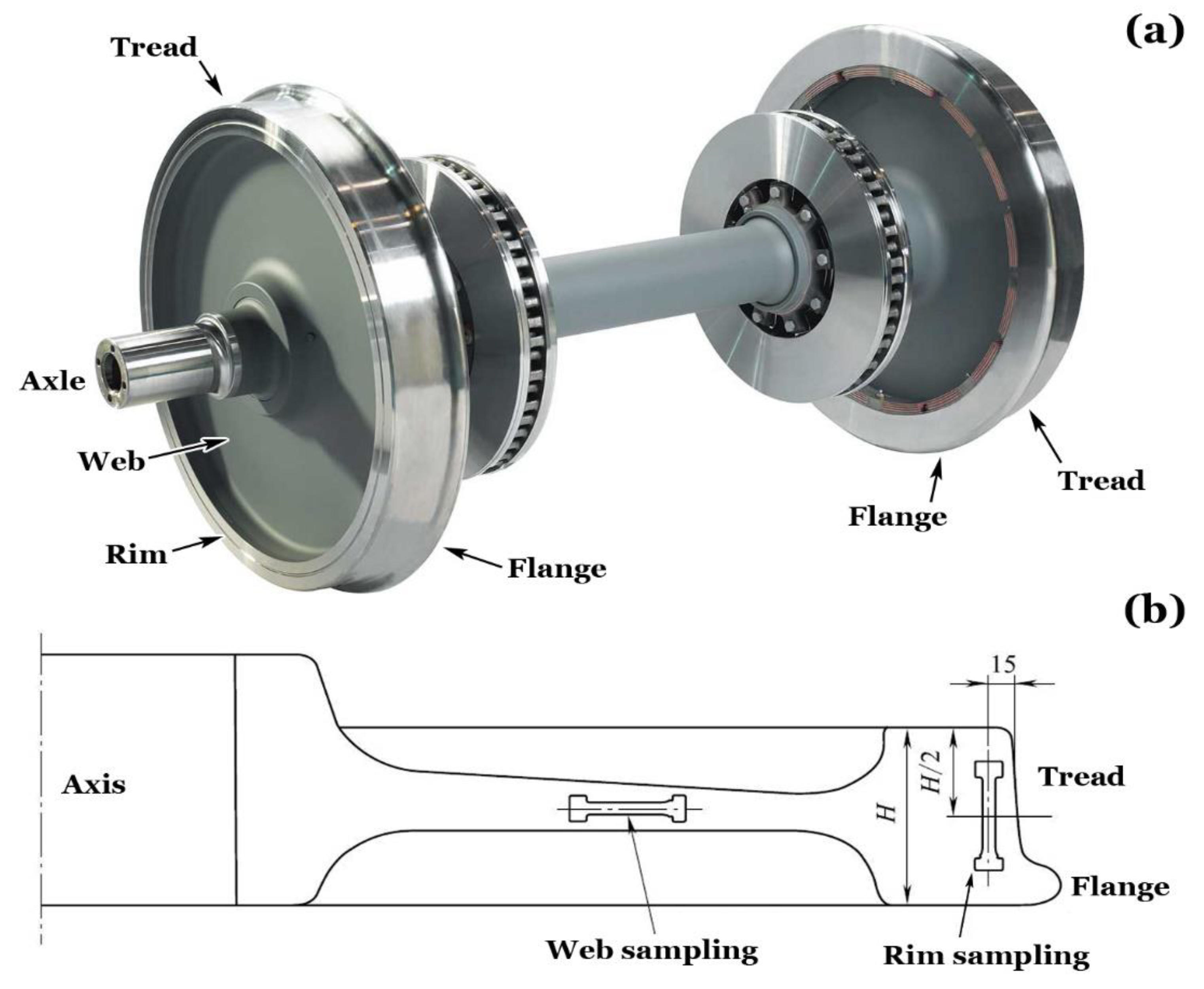
Figure 2.
Metallographs of cross-sectional microstructure perpendicular to the wheel’s radial direction under varying magnifications and locations.
Figure 2.
Metallographs of cross-sectional microstructure perpendicular to the wheel’s radial direction under varying magnifications and locations.
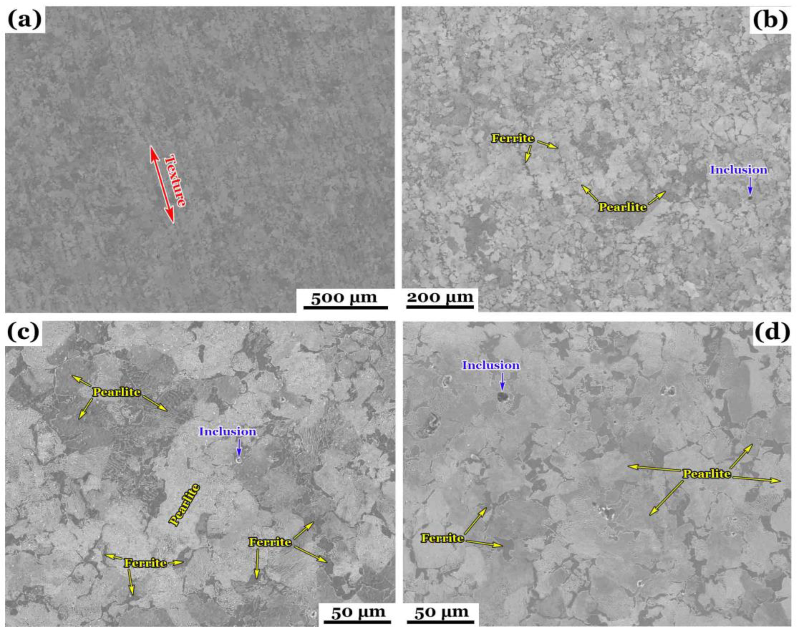
Figure 3.
Metallographs of wheel rim perpendicular to the wheel’s axis under varying magnifications and locations.
Figure 3.
Metallographs of wheel rim perpendicular to the wheel’s axis under varying magnifications and locations.
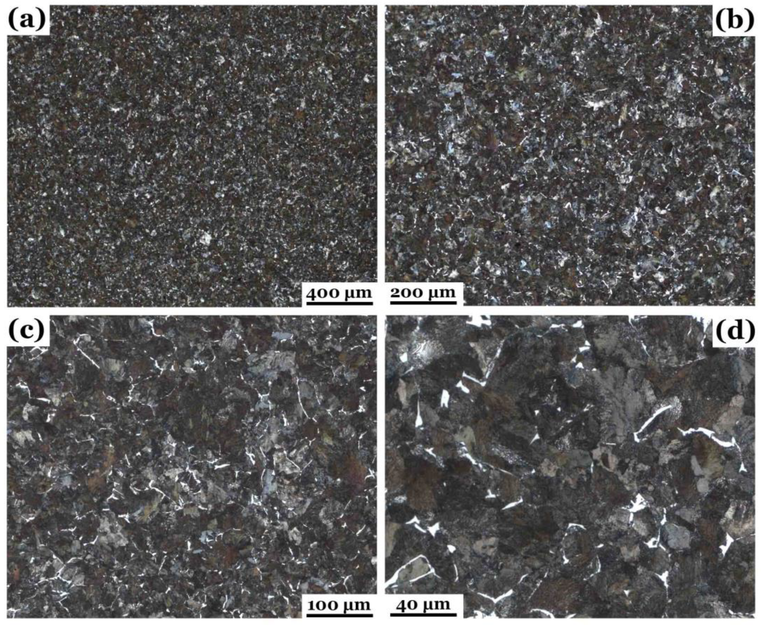
Figure 4.
Metallographs of wheel rim parallel to the wheel’s axis under varying magnifications and locations.
Figure 4.
Metallographs of wheel rim parallel to the wheel’s axis under varying magnifications and locations.
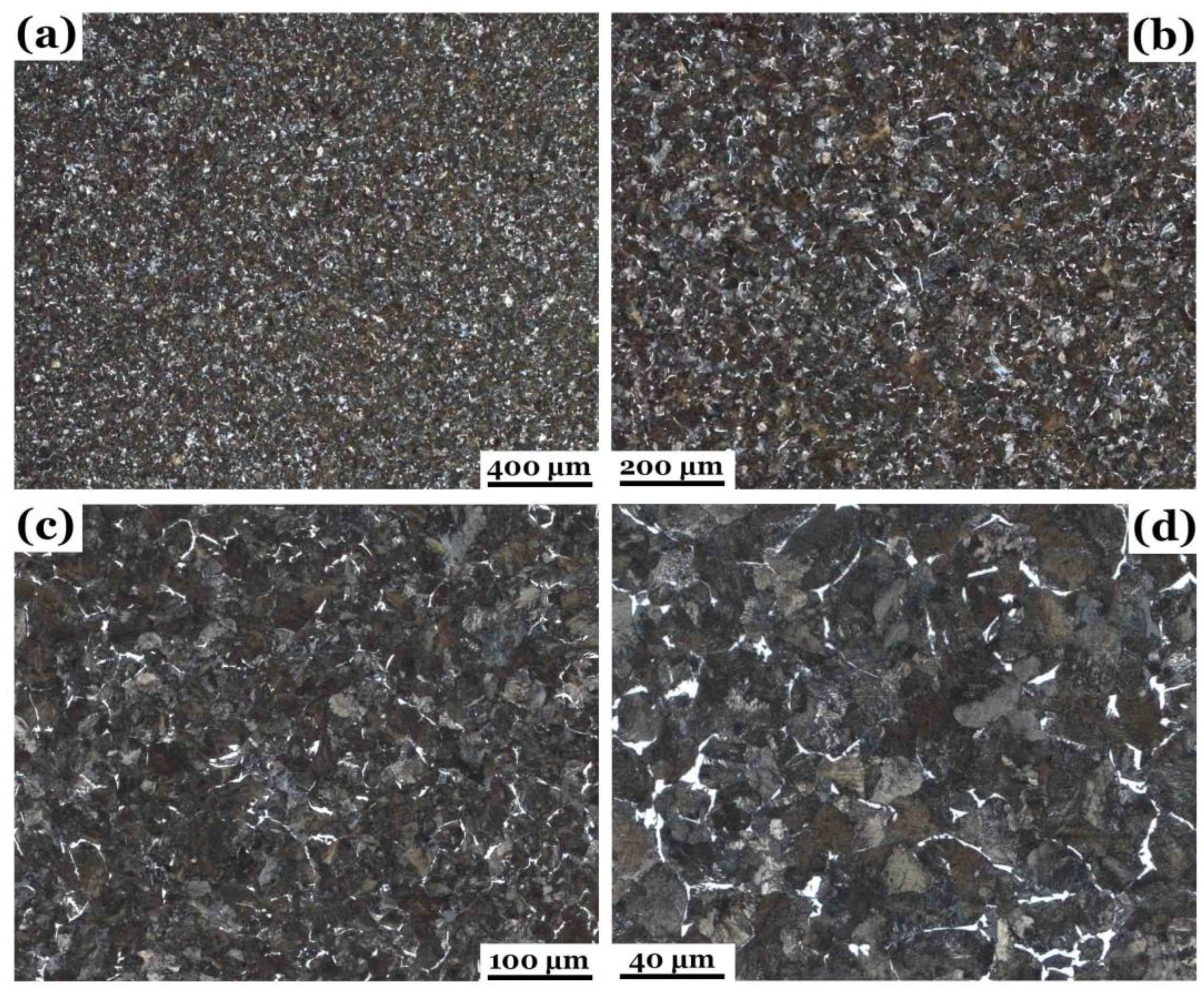
Figure 5.
SEM images of wheel rim perpendicular to the wheel’s axis under varying magnifications and locations.
Figure 5.
SEM images of wheel rim perpendicular to the wheel’s axis under varying magnifications and locations.
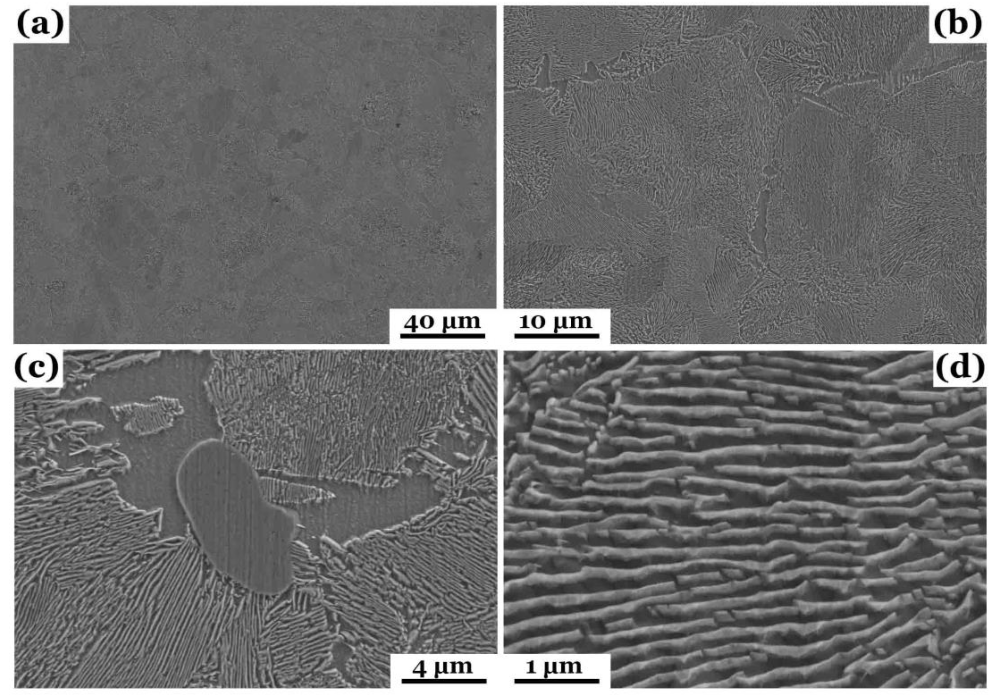
Figure 6.
SEM images of wheel rim parallel to the wheel’s axis under varying magnifications and locations.
Figure 6.
SEM images of wheel rim parallel to the wheel’s axis under varying magnifications and locations.
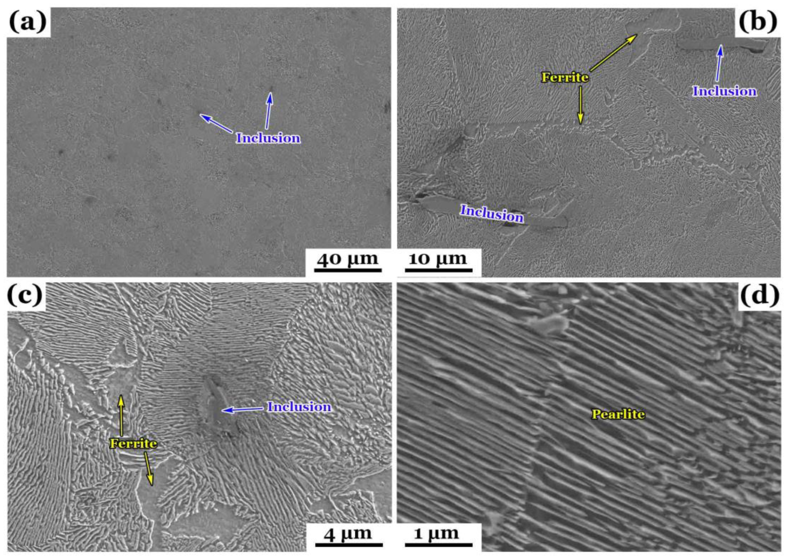
Figure 7.
Microhardness (in HBW) distributions on different longitudinal sections of a wheel rim.
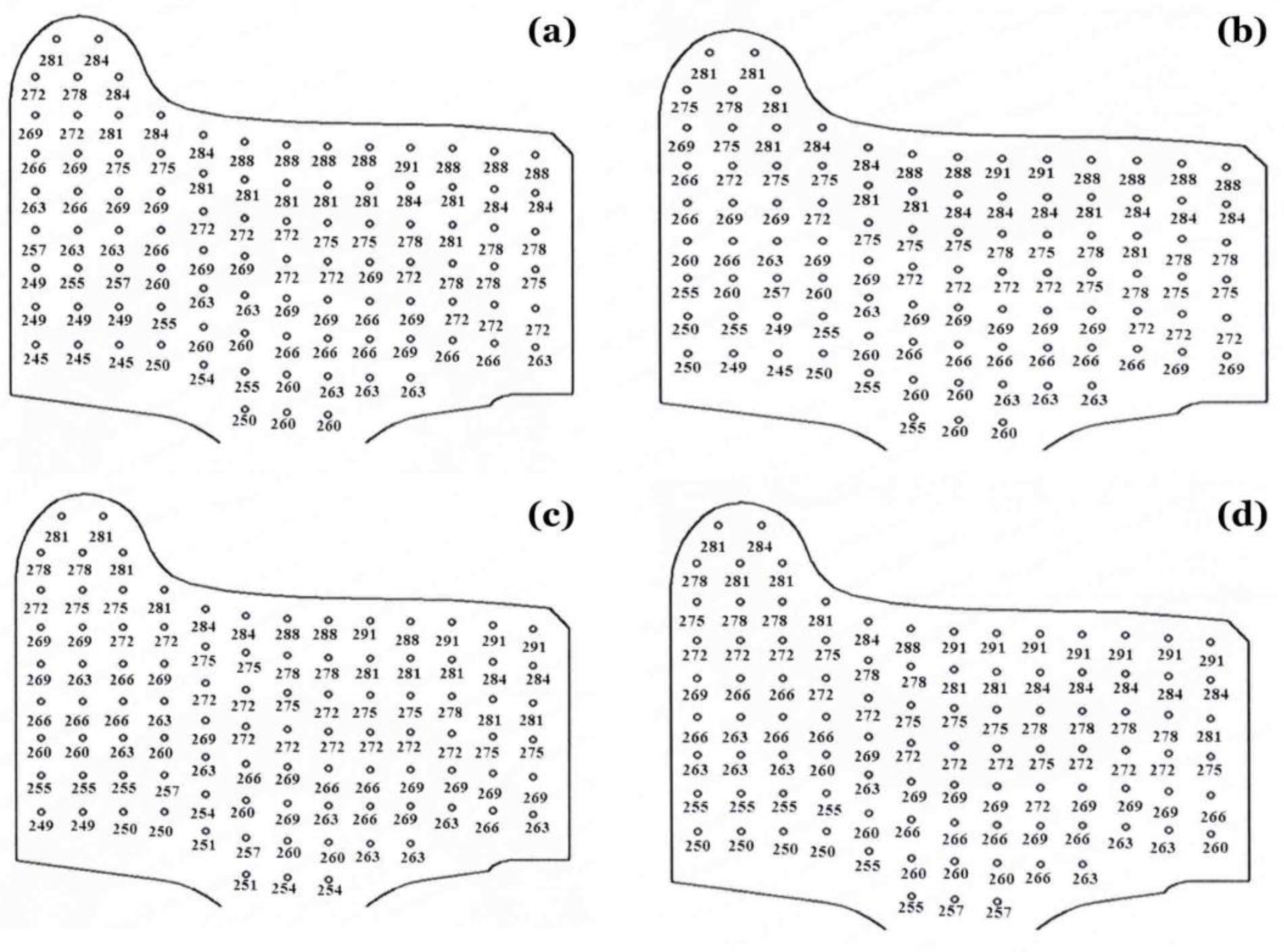
Figure 8.
Schematic diagram of the four-point rotating bending fatigue testing machine.

Figure 9.
Illustration of fatigue specimen clamping and its stress distribution.
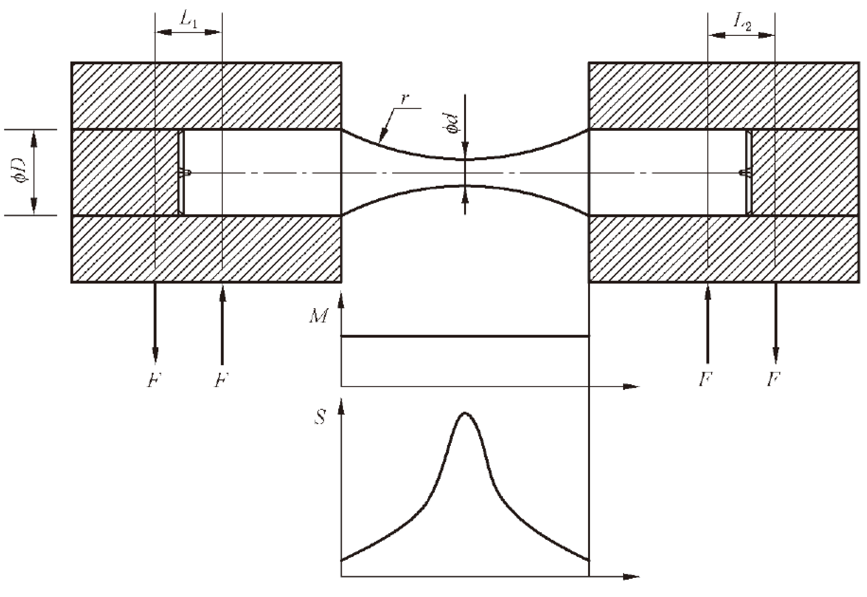
Figure 10.
S-N data of two batch specimens represented in different colors: (a) overall, (b) enlarged.
Figure 10.
S-N data of two batch specimens represented in different colors: (a) overall, (b) enlarged.
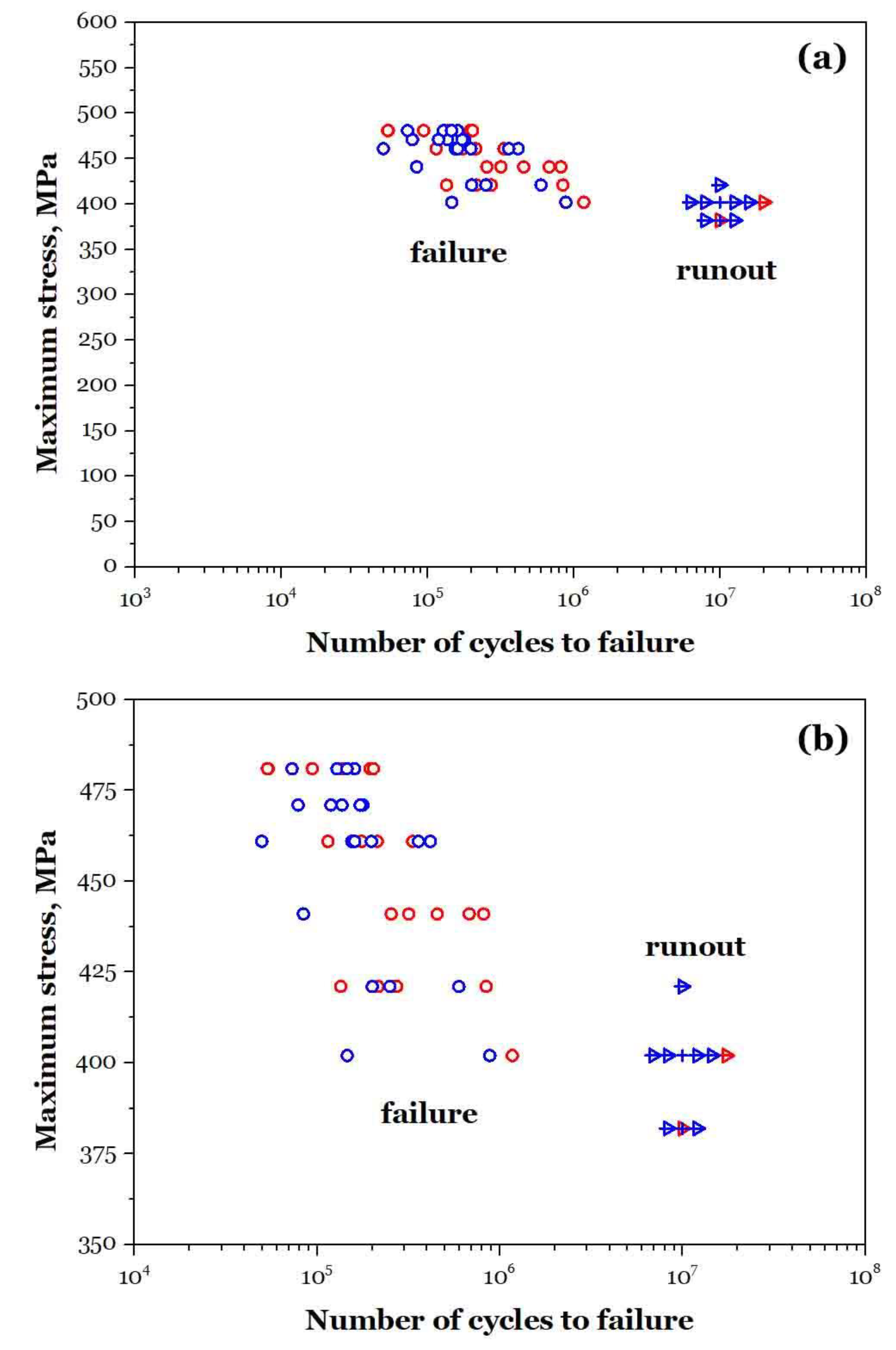
Figure 11.
Loading results obtained by the staircase method, with different colors representing different batches (a) and (b).
Figure 11.
Loading results obtained by the staircase method, with different colors representing different batches (a) and (b).
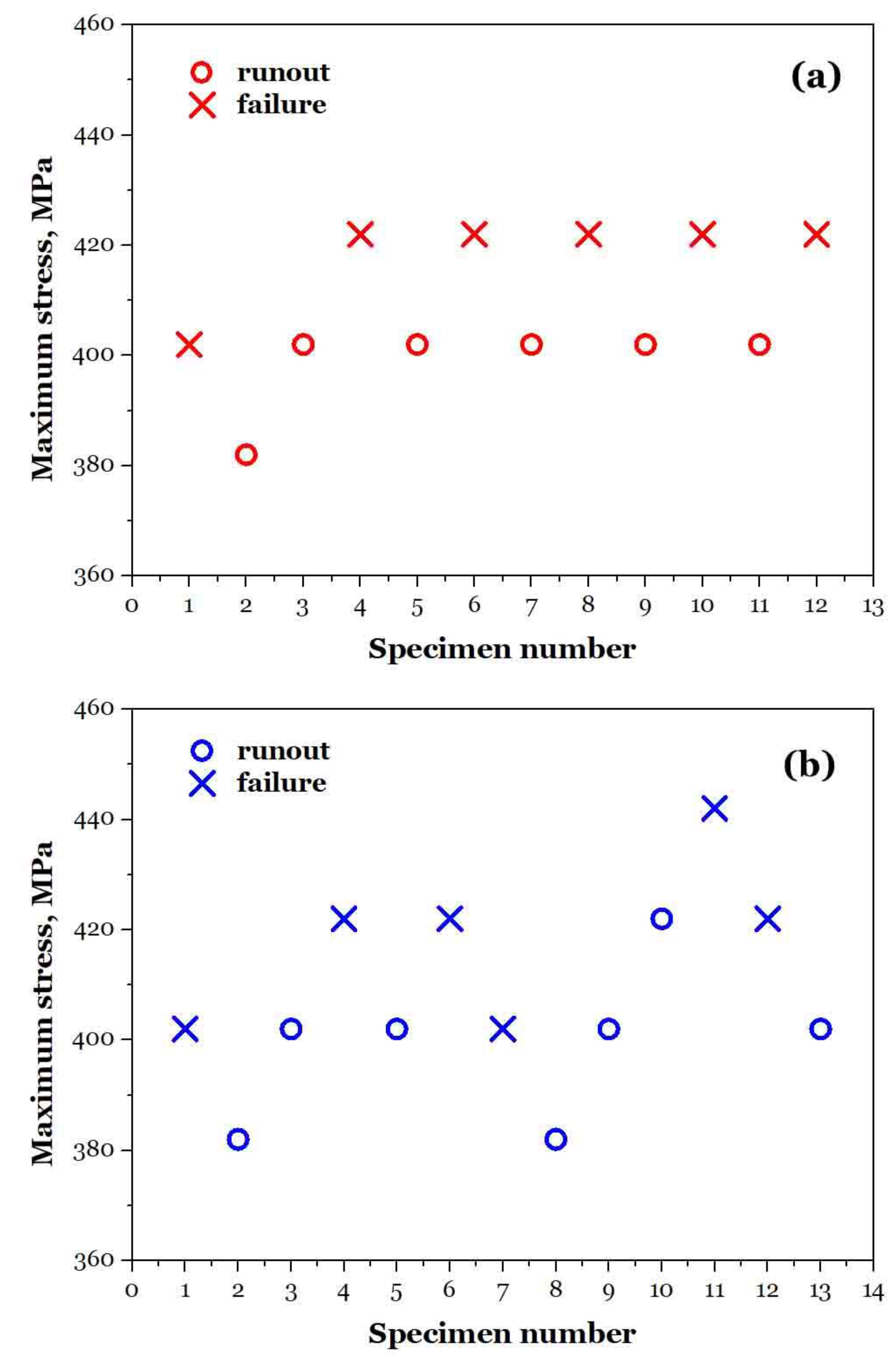

Table 1.
Chemical compositions (in weight percent) for a high-speed train wheel.
| C | Si | Mn | P | S | Cr | Cu | Ni | Mo | V | Cr+Ni+Mo | |
|---|---|---|---|---|---|---|---|---|---|---|---|
| Required | ≤ 0.56 | ≤ 0.40 | ≤ 0.80 | ≤ 0.02 | ≤ 0.015 | ≤ 0.30 | ≤ 0.30 | ≤ 0.30 | ≤ 0.08 | ≤ 0.06 | ≤ 0.50 |
| Measured | 0.54 | 0.30 | 0.75 | 0.013 | 0.007 | 0.18 | 0.20 | 0.10 | 0.04 | 0.003 | 0.32 |
Table 2.
Tensile properties of specimens extracted from the wheel’s rim and web.
| The wheel rim | The wheel web | ||||||
| σu | σy | δf | ψf | σu | δf | ψf | |
| Required | 860 ~ 980 MPa | ≥ 540 MPa | ≥ 13% | - | 740 ~ 860 MPa | ≥ 16% | - |
| Measured | 929 MPa | 602 MPa | 17.0% | 46% | 779 MPa | 21.0% | 42% |
Disclaimer/Publisher’s Note: The statements, opinions and data contained in all publications are solely those of the individual author(s) and contributor(s) and not of MDPI and/or the editor(s). MDPI and/or the editor(s) disclaim responsibility for any injury to people or property resulting from any ideas, methods, instructions or products referred to in the content. |
© 2025 by the authors. Licensee MDPI, Basel, Switzerland. This article is an open access article distributed under the terms and conditions of the Creative Commons Attribution (CC BY) license (http://creativecommons.org/licenses/by/4.0/).
Copyright: This open access article is published under a Creative Commons CC BY 4.0 license, which permit the free download, distribution, and reuse, provided that the author and preprint are cited in any reuse.


