
Submitted:
01 June 2025
Posted:
02 June 2025
You are already at the latest version
Abstract
The forming process is related to the conventional external inversion of tube ends with some modifications that result in different deformation mechanics from those of conventional tube forming. Different techniques are analysed to identify the values of the major process variables that allow us to obtain sound hollow toroidal shells with free rotation of the coin blank. The work approach consists of finite element modelling that is complemented by experimentation to evaluate the overall influence of the main parameters in the joining process.
Keywords:
Toroidal Shells
; Tube Forming
; Joining by Forming
; Coin Minting
1. Introduction
The combination of joining by forming with coin minting has been applied to the development of disruptive collector coins with innovative functionalities and alternative materials such as a new type of bi-material coin with a polymer centre and a metal ring [1], where the deformation of the polymer core can be controlled [2] so that to provide the incorporation of advanced security features and/or aesthetic effects.
Although coin minting is an old metal-forming process that has been studied for many years [3], its development is far from concluded since mints are competing worldwide to present technological and state-of-the-art products with complex shapes and disruptive materials [4]. As for other forming processes, finite element models are employed to predict plastic flow and distributions of strain, stress and damage, as well as force requirements [5]. The utilization of this software allows us to solve typical setbacks during production extending tool life and therefore reducing the production costs [6].
The integration of tube-forming operations such as tube flaring to produce single-lap flanges by compressing the free tube end with a contoured die has been utilized for producing joints between tubes and tubesheets [7] and between tubes and sheet panels [8]. These tube-forming operations will thereby be extended to the production of double-lap flanges obtained by axial compression of the ends of a tube with two hemi-toroidal shaped dies until achieving the desired geometry and producing a loose connection with a disk blank, that allows the two elements to rotate upon each other. The forming process follows the principle of shaping thin-walled tubes into toroidal shells [9] in a single- or double-stage operation according to the coin design specifications.
The tool setup is presented in Figure 1 where the process variables of the tube and the flaring radius define the axis of the rotation and the cross-section of the shell. To avoid smashing the tube ends against the disk and/or to prevent fracture during forming, restrictions need to be introduced to both the dies and the geometry of the preforms, as will be discussed in the paper.
The main purpose is to introduce a solution for coin minting that relies on conventional external inversion of tubes [10] to obtain sound hollow toroidal shells from end-forming of thin-walled tubes [9,11] with free rotation of the coin blank, creating new effects and possibilities for the coin collector market. The appropriate geometries of both the tube and blank are evaluated with different designs, along with the force and energy requirements for each solution, as well as their feasibility employing numerical and experimental analysis. This will allow to understand the mechanics of deformation behind the joining process of the two elements and to identify the main operating parameters that establish the limits of the process. Two different cross-sections for the toroidal shells are analysed and strategies are provided to produce the free mechanical connection in one single stage or two consecutive operations according to the intended coin design, to give an effective contribution to the knowledge transfer of this technology.
2. Materials and Methods
2.1. Stress-Strain Behaviour of the Tube and Disk Material
The research started with the mechanical characterization of the materials of each element to be employed in the fabrication of the coins with a rotating element. Since this concept will be initially applied to proof coins, the chosen material for both elements was Silver (Ag925). The stress-strain response of the material was obtained from stack compression tests performed in piled-up cylindrical specimens cut from the original geometries in which the materials were supplied. Due to their manufacturing process, the stress-strain curve of the tube and disk presents slight differences, as can be observed in Figure 2. Those differences can also be justified by the different levels of superficial micro hardness verified, with the tubes having a Vickers hardness of 128 HV while the disks have a Vickers hardness of 114 HV, which confirms the higher levels of strain-hardening suffered by the tubes as a result of their manufacturing process, and justifies that for the same strain levels, the tube material presents higher stress levels than the disk, despite their similar chemical composition.
Coin blanks with a diameter of 32.65±0.05 mm and a thickness of 1.65 mm, having a central hole with a diameter of 8.25 mm. The tubes have an external diameter of 7.50 mm, a thickness of 0.75 mm and different heights (refer to Table 1) were utilized in the entire set of tests that were performed at the hydraulic testing machine INSTRON SATEC 1200 kN with a constant crosshead speed of 10 mm/min at ambient temperature.
2.2. Forming of Toroidal Shell
Two different cross-sections were analysed for the fabrication of the toroidal shells that are the basis of the coin with a rotating element: a circular section (Figure 3a) and a non-circular C-shape section (Figure 3b). These two types of sections allow to produce different aesthetic effects and at the same time offer a proper control of the gap between the toroidal shell and the disk.
The main process variables other than the initial variables of the tubular preform are the internal diameter and external diameter of the correspondent toroidal shell and its final height . That internal diameter cannot be lower than the initial disk thickness if a totally circular toroidal shell that embraces the disk is to be guaranteed.
The main differences between the two iterations are that the non-circular section allows to have a toroidal shell with much lower volume than the circular section, without a protrusion above the disk and with a straight inner wall. This allows to have a larger area for engraving while the rotation is guaranteed by the chamfered hole that acts as a rotation pivot.
The free rotation in the non-circular section is assured by a localized and discontinuous contact in-between the toroidal shell and disk, which in comparison with the larger contact verified on the circular section, allows for higher levels of rotation of the two elements upon each other.
3. Numerical Simulations
The finite element software i-form [12] was employed to produce numerical predictions of the forming of thin-walled tubes into toroidal shells since they were performed under a quasi-static constant displacement rate and no inertial effects nor dynamic effects in the forming mechanisms need to be considered. An extension of the finite element flow formulation to include the relaxation of the incompressibility condition of the velocity field by means of a penalty function and the contact between rigid and deformable objects is the basis of the numerical modelling software.
The initial cross-sections of the tubular and disk preforms were modelled as deformable isotropic objects subjected to axisymmetric loading, discretized by means of four-node axisymmetric quadrilateral elements as depicted in Figure 4, given the rotational symmetry of the forming operation and that no anisotropy effects were considered.
The number of quadrilateral elements was chosen following different convergence analyses for adequate modelling of the distribution of the field variables and force-displacement evolutions. A total average of approximately 300 quadrilateral elements were utilized to discretize the cross-section of the tube, while an average of 1500 quadrilateral elements were utilized for the cross-section of the disk.
In regards to friction, the dies were discretized by contact-friction linear elements and modelled as rigid objects. A law of constant friction was employed to model friction on the forming operation, where is the friction factor and is the flow shear strength friction. A friction factor of 0.1 was utilized on the contact interfaces between the dies and objects, which provided the most compatible results between the predicted numerical forces and experimental results.
The utilization of a dual-grid material point method (MPM), which avoids mesh distortion and decreasing time steps that often occur in finite element modelling, can be used in alternative to achieve higher simulation accuracy and computational efficiency [13].
4. Results and Discussion
4.1. Forming of a Toroidal Shell of Circular Section
For the analysis of the production of a toroidal shell of circular section, tubes with initial heights of 7 and 9 mm were employed in the tool presented in Figure 1. The numerical analysis of those preforms allowed us to conclude which are the conditions for the existence of a free rotation of the toroidal shell over the disk.
The plastic deformation of the tubular preforms during forming results from the mechanisms of flaring and friction. The first takes place when the tube starts to be axially compressed being forced to flare along the tool radius, whereas the influence of friction becomes noticeable until the toroidal shell is completely formed. As will be seen, the surface of the forming tools in contact with the silver tubes and disk needs to provide lower levels of friction to avoid aesthetic defects and/or material flow defects.
Two different situations are presented in Figure 5, starting with an initial tube height of 7 mm (Figure 5a) and 9 mm (Figure 5b) without a gap between the tube and mandrel. As can be observed by the distributions of effective stress in the initial and final stages of deformation, both the upper and lower sections of the circular toroidal shell are subjected to high levels of stress which may create defects in the torus surface as well as premature tool wear. With regards to the cross-section, the utilization of a larger tube height (Figure 5b) gives rise to the creation of a toroidal shell that is not completely circular but instead has a straight vertical inner wall that may produce an undesirable mechanical interlocking that will constrain the rotation movement of the shell as intended.
Utilizing a gap between the tubular preform and mandrel plays an important role in the operation's success. In fact, when no gap exists between the tubular preform and mandrel as shown in Figure 6a, it allows to produce a fully circular toroidal shell with reduced stress levels, due to reduced friction between the tube and dies, since the beginning of the forming operation is mostly localized at the radius of the flaring dies. This gap needs however to be controlled to avoid the risk of the occurrence of plastic instability, since when a gap of 0.75 mm was created between the tubular preform and mandrel as shown in Figure 6b, the contact between the tube and flaring dies was initiated near the end of the flaring radius.
A symmetrical deformation between the upper and lower region of the torus free from defects can then be produced, as seen from the isolated tube forming operation (without the disk) of Figure 6a. The dimension of the internal diameter of the toroidal shell which is necessary to machine the hole in the disk in which the tubular preform will be positioned, as well as the value of the other process variables are summarized in Table 2.
The photographs of the experimental tests obtained under the conditions of Figure 6a are presented in Figure 7 where a toroidal shell of circular section is formed in a raw disk. The tube is firstly positioned in the disk hole (Figure 7a), then the upper die which contains a flaring radius of 1 mm is positioned at the top of the tube (Figure 7b) and will produce an axial compression that is responsible for forming the toroidal shell.
After the process is finished, the dies are removed and the disk with the rotating element is completed (Figure 7c). If the disk is already engraved, the coin is produced in a single stroke.
Under these conditions, a free rotation exists between the toroidal shell and disk with a reduced gap between the two elements, thus increasing the perceived quality of the final product. At the same time, in functional terms, this reduced gap leads to a soft rotation movement and avoids the penetration of debris that may block the rotation of the assembly. In energetic terms, the necessary force to produce the coin with a rotating element is limited to the forming force of the toroidal shell since only the deformation of the tube is verified. The elastic recovery of the tube material is reduced and does not seem to have a significant influence on the rotation movement. The same is verified with the anisotropy of the tube material and the resulting differences in the cylindricity of the toroidal shell.
4.2. Forming of a Toroidal Shell of Non-Circular Section
While the production of a toroidal shell of circular section demands a considerable volume that will brace the circular disk, the production of a non-circular toroidal shell allows to obtain a bigger engraving area and it utilizes a chamfered disk hole as a rotation pivot. This toroidal shell presented in Figure 8 also reduces the overall thickness of the assembly, but it still allows the utilization of disks of larger thickness without protrusions above its surfaces by producing a straight inner torus wall. The free rotation is guaranteed in this case by a discontinuous and localized contact that offers higher levels of rotation than the previous technique.
The different set of tools (refer to Figure 8) consists of an upper and lower punch with a given flaring radius, that will perform the forming operation of the non-circular torus up to a displacement where it will be very close to the chamfered hole of the disk. To ensure inner straight walls, the tool setup also includes a removable internal mandrel and in contrast with what was observed for toroidal shells of circular sections, no gaps are now necessary between the tubular preform and mandrel. A relief angle should however be introduced in the mandrel to allow the extraction of the coin without damaging the toroidal shell. A small radius of 0.05 mm should also be included in the boundary regions of the punches to create a support region for the engraved disk to be correctly positioned, thus avoiding rotation defects and/or damage to its surfaces
The tool for controlling the gap (Figure 8b) is composed of two punches with the same radius that were utilized for the first stage where the torus was formed (refer to Figure 8a). The operation consists in the axial compression of the toroidal shell with those punches to force the material of the torus to flow in the opposite direction of the disk, thus creating the desired gap between the surfaces if not admissible due to possible material variations.
For the determination of the optimal flaring radius that allows to obtain the C-shaped section, tubes with smaller initial heights of 4 and 6 mm were selected and disks with a chamfered hole were prepared. An initial height of 4 mm has shown to be the critical height above which plastic instability of the tube wall is verified for the tooling system employed. For this height of 4 mm only a local thickening of the tube wall is observed, and the values of the remaining working variables before the calibration of the gap with the tool of Figure 8b are summarized in Table 3.
Regarding the flaring radius , a flaring radius of 1 mm was previously utilized to produce a toroidal shell of circular section. From the numerical simulations, it was seen that a very small radius of 0.5 mm is not able to produce a toroidal shell of non-circular section without defects and constraints material flow during the forming operation. By its turn, a radius of 0.75 mm (in between 0.5 and 1 mm) presents itself as the best compromise as seen by the evolution of Figure 9, where it can be observed that the forming of the toroidal shell occurs until a displacement where it is almost in contact with the chamfer of the disk. At this point, the process is terminated to guarantee a free rotation movement between those elements and if needed, a secondary operation can be performed with the tool of Figure 8b to calibrate the gap between the torus and disk, to ensure the desired levels of rotation.
In comparison with a toroidal shell of circular section, this variant demands lower forming force due to the reduced tube height and consequently a reduced tool displacement becomes necessary to produce the disk with the rotating element.
Both techniques are characterized by a load-displacement curve where the load increases gradually with the axial compression of the tube and the main deformation mechanisms that govern the material flow behaviour start to be triggered. Those mechanisms are the bending as the tube initiates the contact with the dies and stretching along the circumferential direction as the tube is forced to deform against the surface contour of the dies. The contact is not uniform along those interfaces but rather limited to specific regions where high values of contact pressure are found and where reduced friction conditions can positively influence the overall forming process.
By analysing the force-displacement evolution of Figure 9 for the production of a toroidal shell of non-circular section, as that to be utilized in the industrial coin production, it can be seen that the load starts to increase from point I to point II, due to a more pronounced bending effect of the tube as it adapts to the contour of the dies. Then, the overall forming load grows moderately and then rapidly until point III, where the upper and lower dies are in full contact with the surfaces of the fully formed toroidal shell, which by its turn makes contact with the disk. From this point, the tool setup is changed and the calibration of the gap between the toroidal shell and disk is performed according to the evolution at point IV. The inserts of Figure 9 allow us to identify the corresponding stage of each point identified in the graph.
Photographs of the set of tools for the fabrication of the non-circular toroidal shell are presented in Figure 10. The conditions of the deformation can be controlled by the tolerances and surface finish of the tools.
After the toroidal shell is formed at the disk hole with the tool from Figure 10a, the tool from Figure 10b can then be utilized to increase the gap between the two parts and produce the desired levels of rotation.
The punches to perform the coining of the disk are presented in Figure 11, where the dimensions of the centre hole at the disk are controlled by a mandrel that is integrated into one of the punches during coin minting.
The original tube with the engraved disk and the final coin after forming of the toroidal shell are presented in Figure 12a and 12b, respectively.
5. Conclusions
Different techniques are presented that are capable of shaping silver thin-walled tubes into circular and non-circular toroidal shells, which act as rotating elements in silver disk coins. The deformation mechanisms are consistent with those of single tube forming in which bending and circumferential stretching are gradually developed as the tubular preform deforms against the contour of the die. The control of the gap between the torus and disk was revealed to be essential to allow for relative rotational movement while ensuring a mechanical connection between those two elements.
The finite element analysis combined with experimentation allowed us to identify and understand the influence of the working variables on the overall process of forming toroidal shells of different sections to obtain the desired geometry.
The surface finish of the dies plays an important role, with reduced friction conditions and parallel surfaces being of the upmost importance for the correct forming of the toroidal shells. The force requirements of the new solution are only dependent on the complexity of the coin reliefs since the forming forces of the different toroidal shells are very reduced. In some cases, the force value can be utilized to control material flow and obtain the desired gap between the coin components, which facilitate the quality assessment of the newly manufactured coins having rotating elements.
In conclusion, the strategies developed under this research work allowed for a successful industrial implementation of these concepts at the Portuguese Mint, which was able to industrialize the process and create new high-added-value coins. The new concepts can be easily extended to different material combinations and more complex designs.
Author Contributions
Experimentation: Luís M. Alves, Paulo Alexandrino, Sónia Pereira; Numerical modelling: Luís M. Alves; Writing-original draft preparation: Luís M. Alves; Writing-review and editing: Luís M. Alves, Paulo Alexandrino, Sónia Pereira; Coordination: Luís M. Alves. All authors have read and agreed to the published version of the manuscript.
Funding
The authors acknowledge Fundação para a Ciência e a Tecnologia (FCT) for its financial support via the projects LAETA Base Funding (DOI: 10.54499/UIDB/50022/2020) and LAETA Programatic Funding (DOI: 10.54499/UIDP/50022/2020).”
Data Availability Statement
The authors confirm that the data and material supporting the findings of this work are available within the article.
Acknowledgments
The authors would like to acknowledge the support provided by the Portuguese Mint (INCM - Imprensa Nacional Casa da Moeda) and Fundação para a Ciência e a Tecnologia (FCT) for its financial support via the projects LAETA Base Funding (DOI: 10.54499/UIDB/50022/2020) and LAETA Programatic Funding (DOI: 10.54499/UIDP/50022/2020).” The authors would also like to thank the technical assistance of Mr. Nuno Caetano and the support of Dr. Sílvia Garcia and Dr. Alcides Gama from INCM.
Conflicts of Interest
The authors declare no conflicts of interest.
References
- Afonso RM, Alexandrino P, Silva FM, et al. A new type of bi-material coin. Proc IMechE, Part B: J Engineering Manufacture 2019; 233: 2358–2367.
- Afonso RM, Alves LM, Martins PAF. On the buckling of polymer disks. Thin-Walled Struct. 2019; 136: 99-105. [CrossRef]
- Bocharov Y, Kobayashi S, Thomsen EG. The mechanics of the coining process. J. Eng. Ind. 1962; 84: 491–501.
- Rosado PM, Sampaio RFV, Pragana JPM, et al. Joining by forming of bi-material collector coins with rotating elements. J Adv Join Process. 2024, 10, 100265. [CrossRef]
- Alexandrino P, Leitão PJ, Alves LM, et al. Numerical and experimental analysis of coin minting. Proc IMechE, Part L: J Mater Des Appl. 2019; 233: 842-849. [CrossRef]
- Alexandrino P, Leitão PJ, Alves LM, et al. Finite element design procedure for correcting the coining die profiles. Manuf Rev 2018; 5: 3. [CrossRef]
- Alves LM, Afonso RM, Martins PAF. A new deformation assisted tube-to-tubesheet joining process. Thin-Walled Struct. 2021; 107784.
- Alves LM, Reis TJ, Afonso RM, et al. Single-stroke attachment of sheets to tube ends made from dissimilar material. Materials 2021; 14: 1–15. [CrossRef]
- Alves LM, Martins PAF. Forming of thin-walled tubes into toroidal shells. J Mater Process Technol. 2010; 210: 689-695. [CrossRef]
- Sekhon GS, Gupta NK, Gupta PK. An analysis of external inversion of round tubes. J Mater Process Technol. 2003; 133: 243–256.
- Alves ML, Almeida BPP, Rosa PAR, et al. End-forming of thin-walled tubes. J Mater Process Technol. 2006; 177: 183–187. [CrossRef]
- Nielsen CV, Zhang W, Alves LM, et al. Coupled Finite Element Flow Formulation. In: Modelling of Thermo-Electro-Mechanical Manufacturing Processes. London: Springer, 2013, pp. 11-36.
- Yin Y, Xu J, Dong J, et al. Cuda-based parallel dual-grid material point method for simulating bimetallic coining process. Comp Part Mech 2025. [CrossRef]
Figure 1.
Schematic representation of the main concept for producing a coin with a rotating toroidal shell at the (a) start and (b) end of the die stroke for a single-stage operation.
Figure 1.
Schematic representation of the main concept for producing a coin with a rotating toroidal shell at the (a) start and (b) end of the die stroke for a single-stage operation.
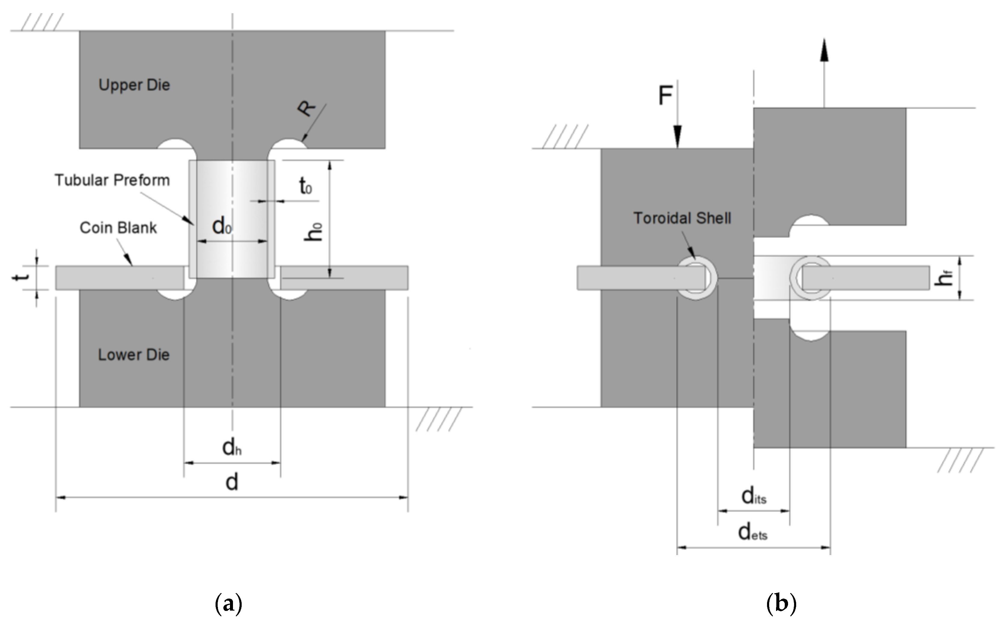
Figure 2.
Flow curves of Ag925 supplied in disk and tube shapes.
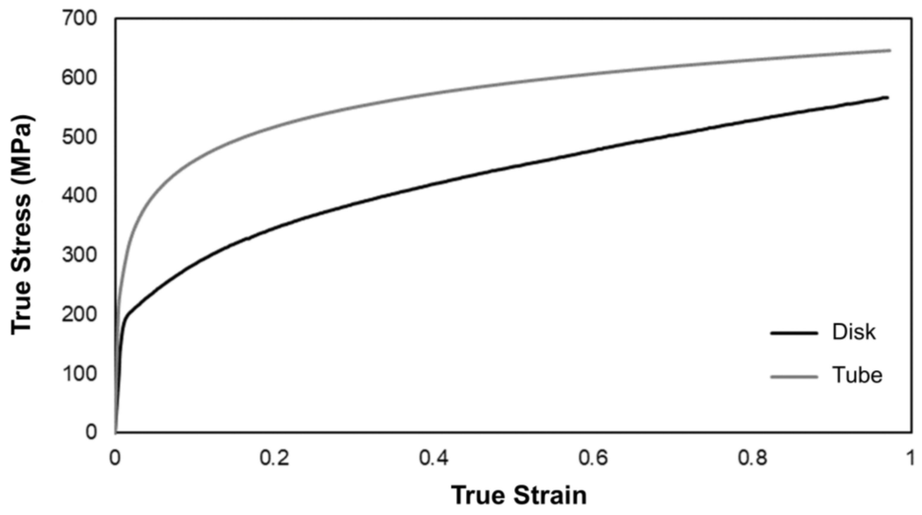
Figure 3.
Comparison between (a) a circular and (b) a C-shape section.
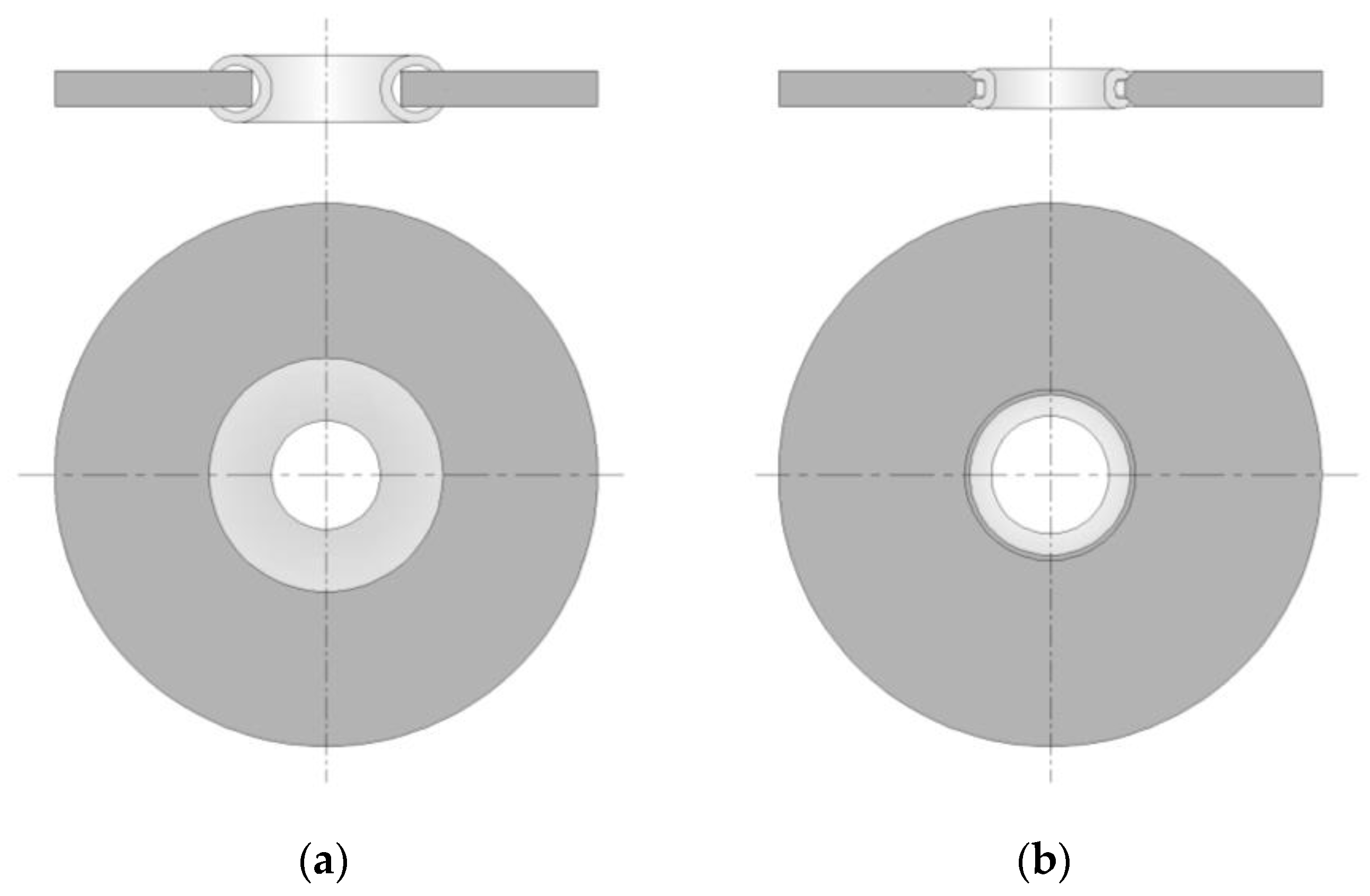
Figure 4.
Numerical meshes for the beginning and end of the forming of the toroidal shell and respective fabrication of the free mechanical joint with the coin blank.
Figure 4.
Numerical meshes for the beginning and end of the forming of the toroidal shell and respective fabrication of the free mechanical joint with the coin blank.
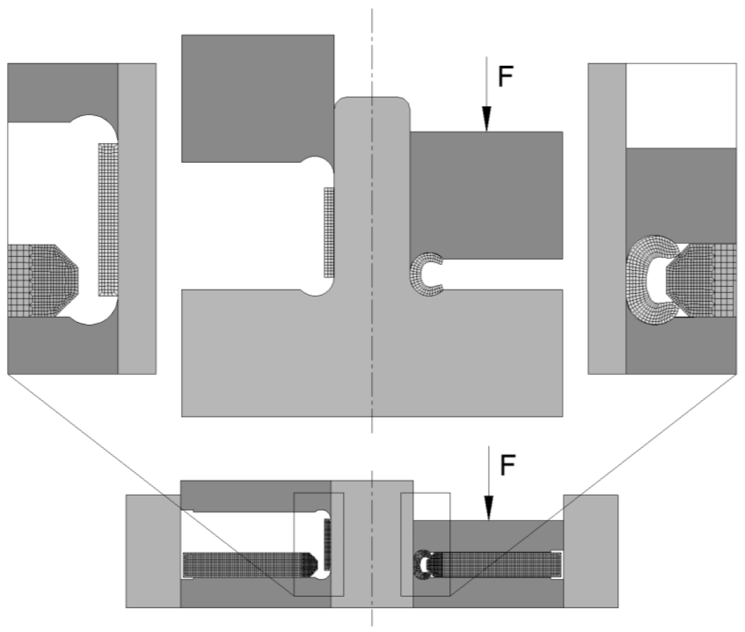
Figure 5.
Distribution of effective stress for tubes with an initial tube height of (a) 7 and (b) 9 mm.
Figure 5.
Distribution of effective stress for tubes with an initial tube height of (a) 7 and (b) 9 mm.
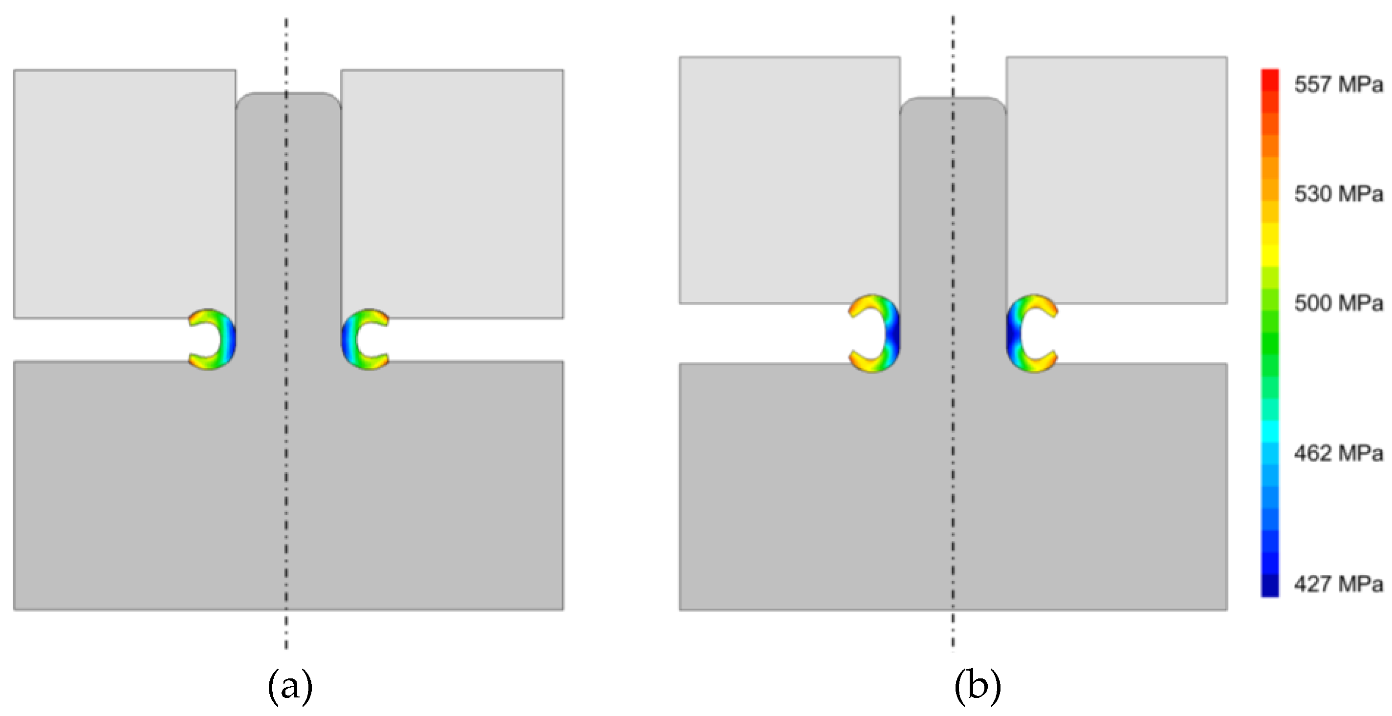
Figure 6.
Effective stress distribution on tubes with an initial tube height of 7 mm without (a) and (b) with a gap between the tubular preform and mandrel.
Figure 6.
Effective stress distribution on tubes with an initial tube height of 7 mm without (a) and (b) with a gap between the tubular preform and mandrel.
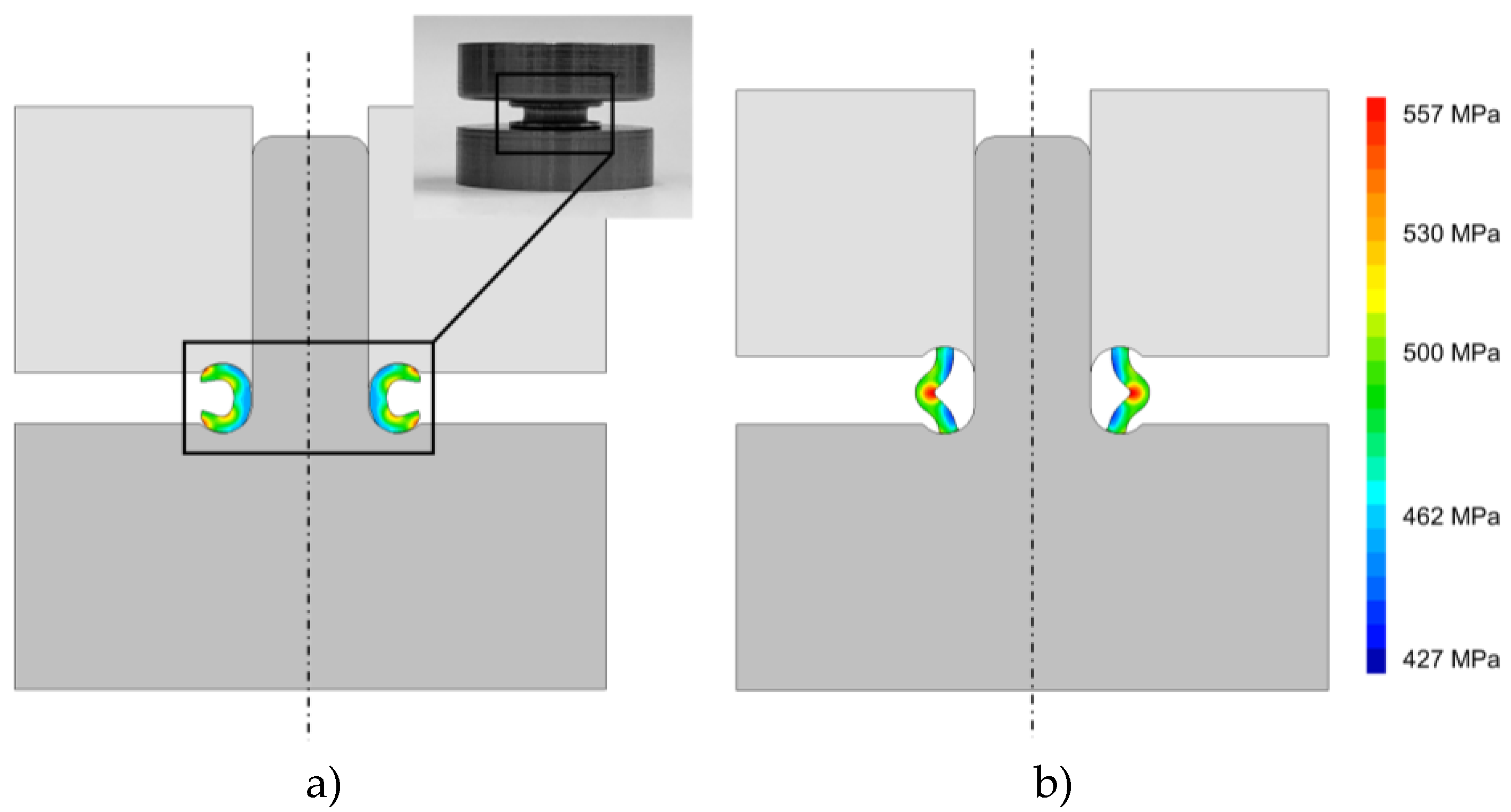
Figure 7.
Different stages of the fabrication of a prototype disk with a toroidal shell of circular section with free rotation for the conditions of Figure 6a obtained with the tool of Figure 1, including (a) positioning of the preforms, (b) forming operation and (c) removal of the upper die.
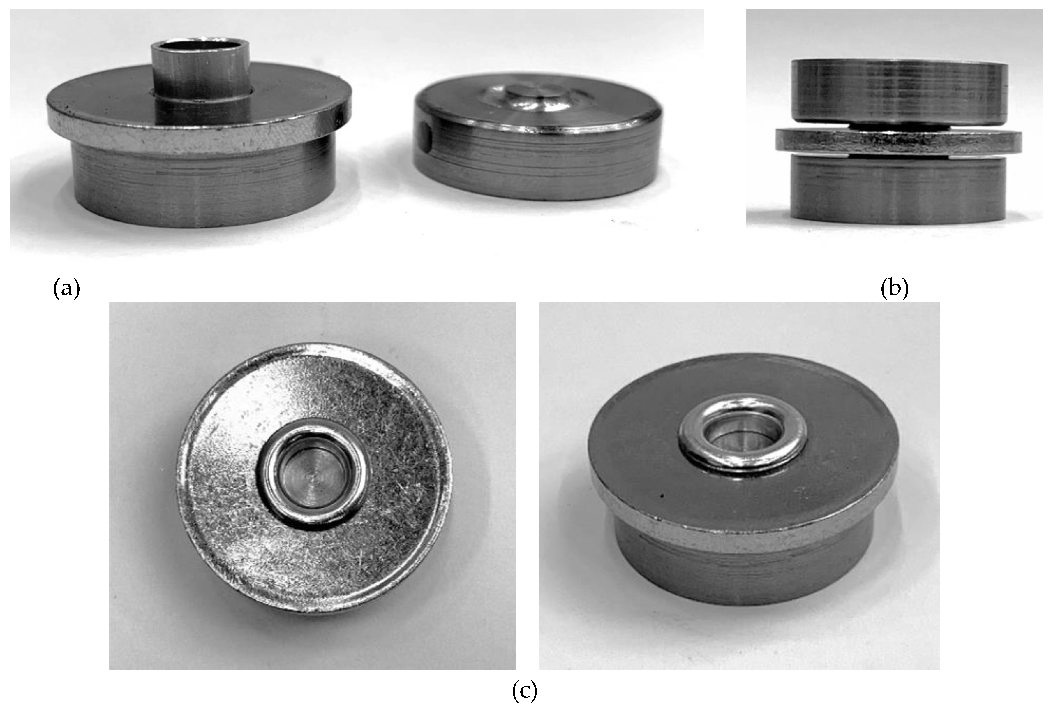
Figure 8.
Schematic representation of (a) the tooling system for the production of a non-circular toroidal shell with the notation of the main process variables and of (b) the tool system to control the gap between torus and disk.
Figure 8.
Schematic representation of (a) the tooling system for the production of a non-circular toroidal shell with the notation of the main process variables and of (b) the tool system to control the gap between torus and disk.
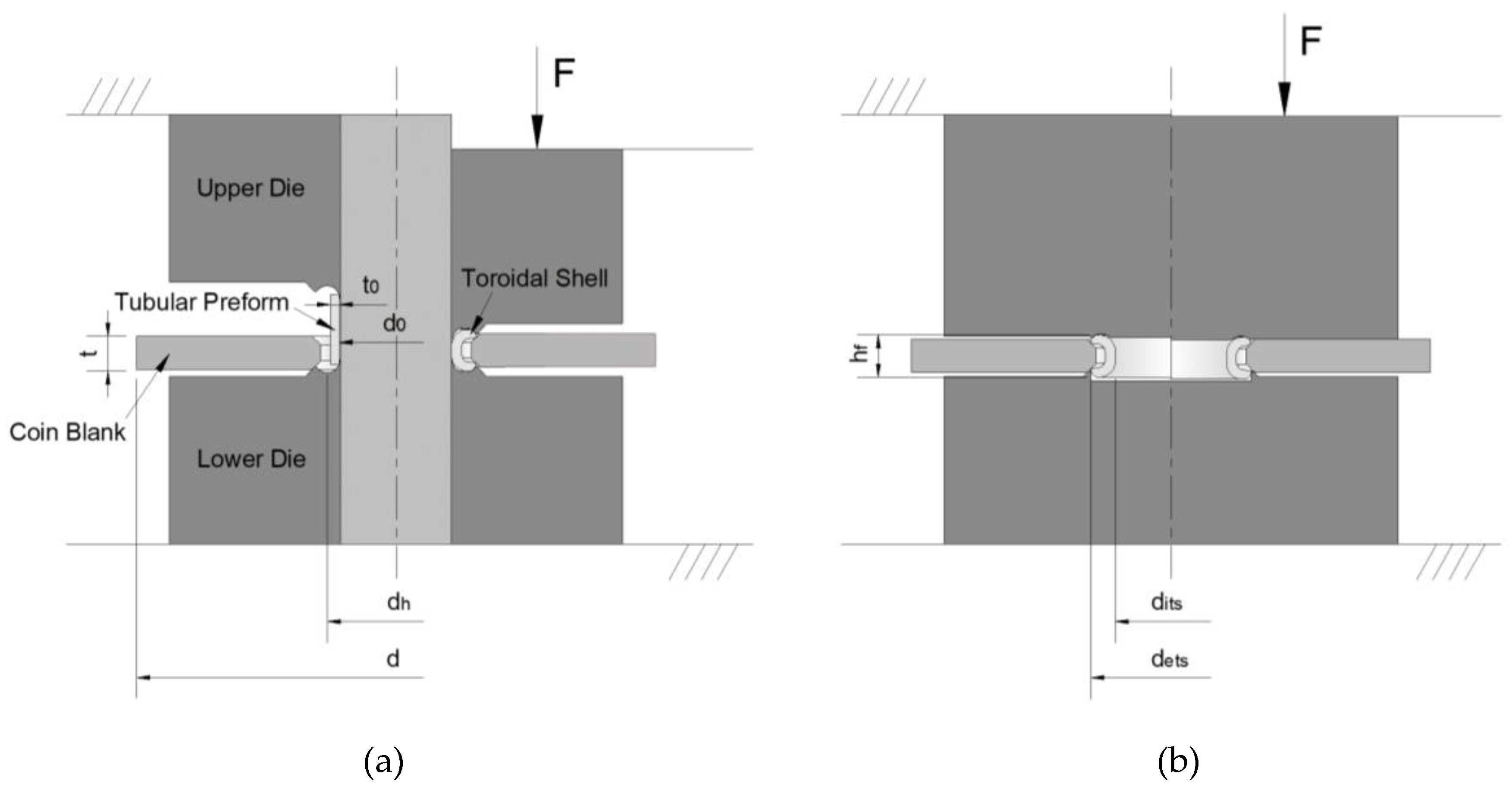
Figure 9.
Experimental and numerical evolution of force-displacement for the production of a toroidal shell of a non-circular section.
Figure 9.
Experimental and numerical evolution of force-displacement for the production of a toroidal shell of a non-circular section.
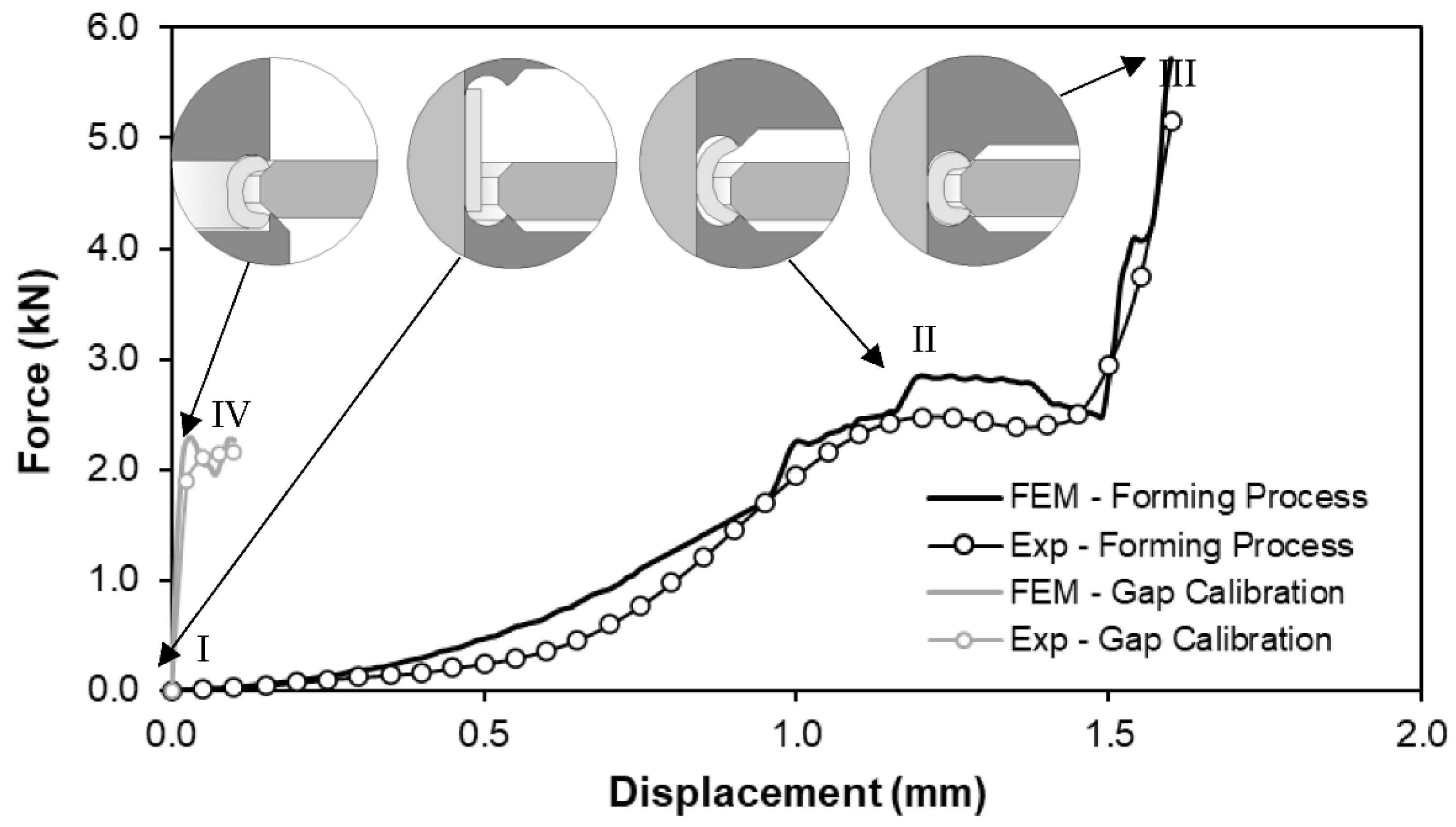
Figure 10.
Set of tools for (a) forming of the toroidal shell in the chamfered hole of the circular disk and (b) for calibration of the gap between them.
Figure 10.
Set of tools for (a) forming of the toroidal shell in the chamfered hole of the circular disk and (b) for calibration of the gap between them.
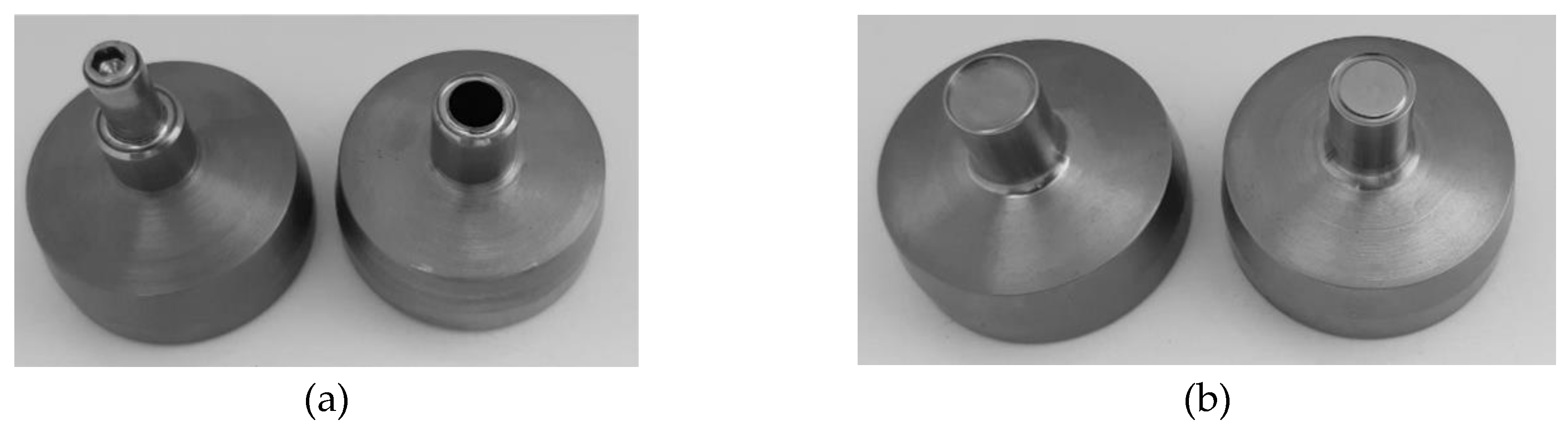
Figure 11.
Engraving punches for coin minting of the disk.
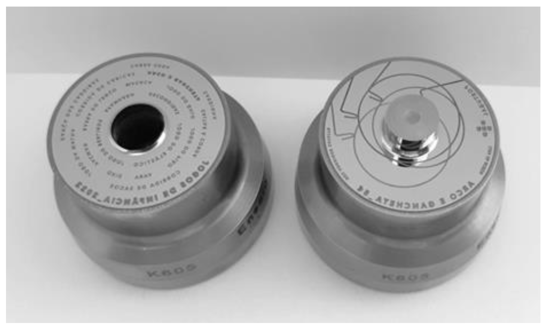
Figure 12.
(a) Preforms and (b) manufactured coin with a rotating element of C-shape section.
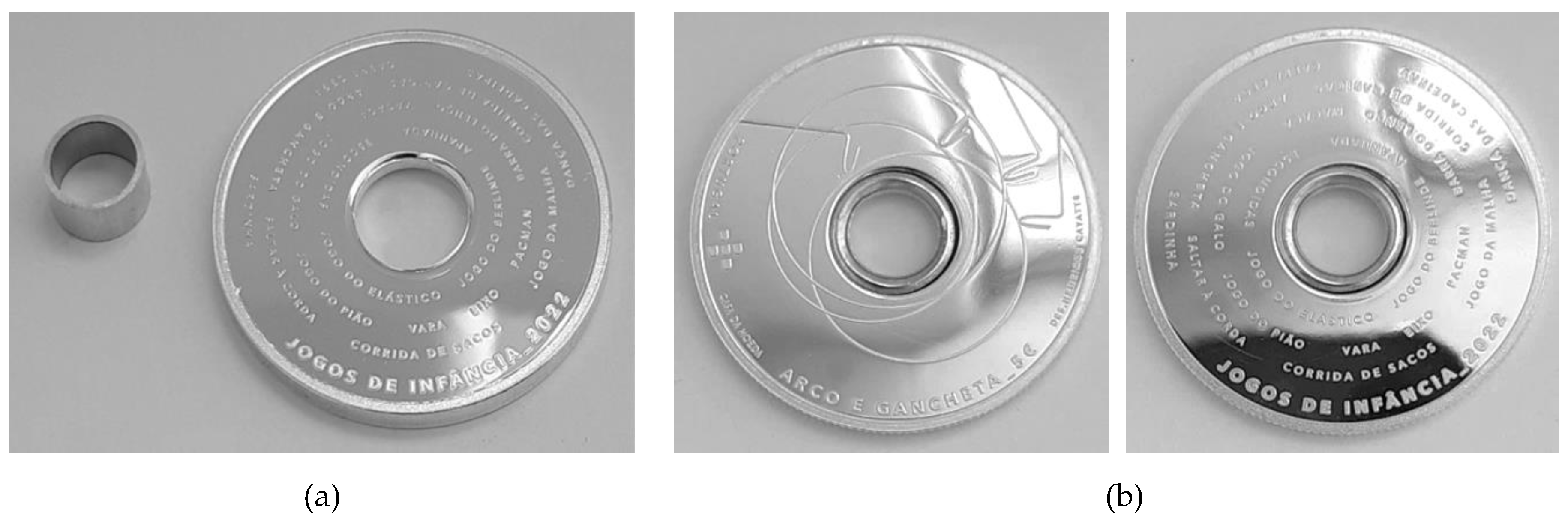

Table 1.
Specifications of the different dimensional parameters analysed.
| (mm) | (mm) | (mm) | (mm) | (mm) | (mm) |
|---|---|---|---|---|---|
| 32.65±0.05 | 1.65 | 8.25 | 7.50 | 0.75 | 4, 6, 7, 9 |
Table 2.
Values of the process variables for the forming of toroidal shells of circular section.
| (mm) | (mm) | (mm) | (mm) | (mm) | (mm) |
|---|---|---|---|---|---|
| 7.5 | 0.75 | 7(without gap) | 6 | 11.12 | 3.39 |
| 7(with a gap) | - | - | 3.62 |
Table 3.
Values of the process variables for the forming of toroidal shells of non-circular section.
Table 3.
Values of the process variables for the forming of toroidal shells of non-circular section.
| (mm) | (mm) | (mm) | (mm) | (mm) | (mm) |
|---|---|---|---|---|---|
| 7.5 | 0.75 | 4.00 | 6.40 | 9.20 | 2.40 |
Disclaimer/Publisher’s Note: The statements, opinions and data contained in all publications are solely those of the individual author(s) and contributor(s) and not of MDPI and/or the editor(s). MDPI and/or the editor(s) disclaim responsibility for any injury to people or property resulting from any ideas, methods, instructions or products referred to in the content. |
© 2025 by the authors. Licensee MDPI, Basel, Switzerland. This article is an open access article distributed under the terms and conditions of the Creative Commons Attribution (CC BY) license (http://creativecommons.org/licenses/by/4.0/).
Copyright: This open access article is published under a Creative Commons CC BY 4.0 license, which permit the free download, distribution, and reuse, provided that the author and preprint are cited in any reuse.


